1
Commercial Air Conditioning
SERVICE MANUAL
MULTI upgrade series
Models
Indoor: AB09CS1ERA
AB12CS1ERA
AB18CS1ERA
AB24ES1ERA
AC12CS1ERA
AC18CS1ERA
AC24CS1ERA
AD09LS1ERA
AD12LS1ERA
AD18LS1ERA
AD24LS1ERA
Outdoor: 3U19FS1ERA
4U25HS1ERA
4U30HS1ERA
5U34HS1ERA
z
z
z
z
z
z
z
z
DC inverter technology, high energy efficiency, higher EER A+, energy
saving for the user
Universal indoor units for multi upgrade series, Unitary smart DC inverter
and HAIER DAC split inverter type
High voltage communication, convenient wiring work
Multiple control types
10℃ constant temperature control
Universal power supply for 50Hz and 60Hz
Central control function available
New friendly refrigerant R410a, zero ODP, environment protection
Manual code: SYJS-017-10REV.0
Edition: 2010-12-10
>_]]VbTZR\ <Zb >_^UZdZ_^Vb
CONTENTS
Contents……………………………………………………….....2
1. Description of products & features………………………….3
2. Specification…………………………………………………...6
3. Dimensions…………………………………………………....21
4. Pipe and wiring installation…..……………………………....26
5. PCB photo, wiring diagram and function description……..72
6. Diagnostic code and troubleshooting.……………………...95
7. Outdoor performance curves………..……………………....101
8. Indoor air velocity and temperature distribution curves......105
9. Air flow and static pressure chart…………………………...111
10. Noise level…………………………………………………...113
11. Sensor characteristic….………………………………….....121
12. Controller functions…...………………………………….....124
-2-
.9773:1506 -5: .9825;5983:
1.Description of products & features
1.1. Products code explanation
U 19 F
S 1 E R A
3
Climate type: T1 (see table 1)
Frequency type: DC inverter
Product type: A stands for heat pump type, refrigerant is R22
B stands for heat pump type, refrigerant is R407C
E stands for heat pump type, refrigerant is R410A
N stands for cool only type, refrigerant is R407C
Design edition
Product series: S stands for EASY STOCK
Product appearance
Cooling / Heating capacity,19=19000BTU/h
Product type : “B” stands for cassette type, “C” stands for
convertible type, “D” stands for duct, “S” stands for wall
mounted type, "F" stands for console type, “U” stands for
outdoor of split unit
Max. 1 to 3
1.2 Brief Introduction for T1,T2,T3 working condition
Climate type
Type
of
Conditioner
Air
T1
T2
T3
Cooling Only
18 ℃~43℃
10℃~35℃
21℃~52℃
Heat pump
-7℃~43℃
-7℃~35℃
-7℃~52℃
Electricity Heating
~43℃
~35℃
~52℃
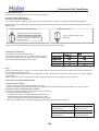
1.3 Operating Range of Air Conditioners
Working temperature range
Cooling
Indoor
outdoor
Heating
Indoor
outdoor
Rated
Maximum
Minimum
DB℃
27
32
18
WB℃
19
23
14
DB℃
35
43
-10
WB℃
24
26
6
DB℃
20
27
15
WB℃
14.5
--
--
DB℃
7
24
-15
WB℃
6
18
--
-3-
Commercial Air Conditioner
1.4 Product features
DC inverter technology, high energy efficiency, higher EER A+, energy saving for the
user
The outdoor unit adopts DC inverter compressor and motor, so save power energy is just to save
money for the user. And the outdoor can match with multiple indoor units, up to 5 sets. Even when
you have already installed the air conditioner, if you want to add or reduce one unit, go ahead freely
as long as your operation complies with our design. Greatly convenient for designer and installer.
Precise control, more comfortable and more reliable
The outdoor is equipped with electronic expansion valve, which will control refrigerant flow more
precisely. As a result, the user will feel more comfortable and the unit is more reliable.
Also, the outdoor is with oil segregator, which will keep the compressor working normally and make
oil return more smoothly.
Universal indoor units for multi upgrade series, unitary smart DC inverter and HAIER
DAC split inverter type
The indoor units are universal for the outdoors which belongs to EASY STOCK series. EASY
STOCK is new concept brought by Haier to be convenient for design, sale, operation, and stock
management.
Adopt the much friendlier refrigerant R410a
The air conditioner system adopts the greatly friendly refrigerant R410a, which is protective for the
ozone layer and is good to avoid the earth getting warmer. Benefit for the environment.
High voltage communication, convenient wiring work
Connect indoor and outdoor directly, and there is no communication wire between indoors. Thus
the wiring work is more convenient. No need to set indoor address.
Multiple control types
The indoor unit can be controlled by multiple types: infrared controller, wired controller, central
controller. More choice, more conveniently.
10℃ constant temperature control
When leave home temporarily, press 10℃ button of remote controller, the indoor temperature won’
t decrease rapidly while be controlled at 10℃. When come back home, press it again, the unit will
be back to normal status and setting temperature.
Auto–restart function (optional)
All indoor units have auto-restart function. When the power supply cut off suddenly, the unit will
automatically recover the previous running mode once the power supply is on.
Self-diagnostic function
In the course of operation, if the failure occurs, the failure code will display on the wired controller or
-4-
Commercial Air Conditioner
on the operation panel. Then according to the failure code chart, you can eliminate the failure soon.
Central control function, if connected with a central controller
That is convenient for building management.
Weekly timing function, if connected with a weekly timer
Universal power supply for 50Hz and 60Hz
The multi upgrade series adopts universal power supply for 50Hz and 60Hz, which is convenient for
design. Much wider application.
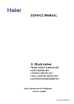
1.5 Product lineup
¾Outdoor unit 220V/1/ (50/60Hz)
Connection diagram
Picture
Cooling capacity(Kbtu)
Max.indoor
quantity
19
25
30
34
3
4
5
Indoor unit 220V/1/ (50/60Hz)
kBTU/h
SERIES
kW
7
9
12
18
24
2.2
2.8
3.6
5.0
6.5
Cassette
Type(4-way)
Floor & Ceiling type
ceiling concealed
duct
HEM
mounted type
Console type
-5-
>_]]VbTZR\ <Zb >_^UZdZ_^Vb
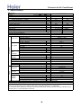
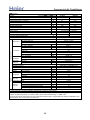
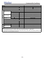
2. Specifications
Item
Model
3U19FS1ERA
Piping
Outdoor unit
Function
Cooling
Heating
Rating capacity
W
5400
6500
Power input (indoor + outdoor)
W
1410
1520
Current input (indoor + outdoor)
A
6.13
6.6
EER / COP
W/W
3.84
4.28
Minimum capacity
W
1500
1800
Minimum power input
W
500
500
Maximum capacity
W
7000
8100
Maximum power input (indoor + outdoor)
W
2600
2600
Power source
1PH, 220-230V~, 50/60Hz
Max.Running current (indoor + outdoor)
A/A
11.3
11.3
Power facor(under rating power input)
99%
99%
Fuse size (recommended size)
16
A
Indoor units number
1~3
Model / Manufacture
SNB130FGYMC-L1 / MGC
500CC, FV 50S
Oil charge and type
Compressor
Twin Rotary (DC inverter)
Type
0.58
Ω
Winding resistance(at 20℃)
Fan type × Number
Axial × 1
Max. 860
Motor speed
r/min
Fan motor model
ARW4403AS
Fan system
Motor type
DC
55/69
Motor output/input power
W
about 2000
Air-flows (H/M/L)
m³/h
TP2M / 7.94
Type / Diameter
mm
Heat
Number of rows
2
exchanger
about 0.52
Face area
m²
886/289/688
Dimension
External
mm
(WxDxH)
990/405/760
Package
mm
PMVs
Refrigerant control method
Defrosting method
Automatic by reversible cycle
Crankcase heater power
35
W
52/-/Noise level
H/M/L
dB(A)
51/ 53
Weight
Net / Shipping
kg / kg
R410A /1.9
Type / Charge
kg
less than 30
Refrigerant
m
Total liquid piping length without recharge
20
Recharge
g/m
3* Φ6.35
Liquid
mm
Pipe size
3* Φ9.52
Gas
mm
Connecting method
Flared
15
Max.Drop between IU & OU
m
7.5
Between
Max.Drop between indoor units
m
IU & OU
25
Max.Piping length between IU & OU
m
50
Max.Total length
m
1. The above performance data are from the combination of 3U19FS1ERA+3*AS09CS1ERA
2. Large drop and long piping installation will obviously reduce the total capacity.
Norminal condition: indoor temperature (cooling): 27℃DB/19℃WB, indoor temperature (heating): 20 ℃DB
Outdoor temperature(cooling): 35℃DB/24℃WB, outdoor temperature(heating): 7 ℃DB/6℃WB
The noise level will be measured in the third octave band limited values, using a Real Time Analyser calibrated sound
intensity meter. It is a sound pressure noise level.
-6-
>_]]VbTZR\ <Zb >_^UZdZ_^Vb
Item
Model
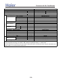
4U25HS1ERA
Piping
Outdoor unit
Function
Cooling
Heating
Rating capacity
W
7600
8600
Power input (indoor + outdoor)
W
2100
2060
Current input (indoor + outdoor)
A
9.1
9.0
EER / COP
W/W
3.62
4.18
Minimum capacity
W
1500
1800
Minimum power input
W
550
550
Maximum capacity
W
9000
9500
Maximum power input (indoor + outdoor)
W
3500
3500
Power source
1PH, 220-230V~, 50/60Hz
Max.Running current (indoor + outdoor)
A/A
15.2
15.2
Power facor(under rating power input)
99%
99%
Fuse size (recommended size)
25
A
Indoor units number
2~4
TNB220FLHMC-L / MGC
Model / Manufacture
870CC / FV50S
Oil charge and type
Compressor
Type
Twin Rotary (DC inverter)
0.88
Ω
Winding resistance(at 20℃)
Fan type × Number
Axial × 1
Max. 860
Motor speed
r/min
Fan motor model
EHDS80A100AS
Fan system
Motor type
DC
100/125
Motor output/input power
W
about 4000
Air-flows (H/M/L)
m³/h
TP2M / 7.94
Type / Diameter
mm
Heat
Number of rows
2
exchanger
about 0.75
Face area
m²
948/340/840
Dimension
External
mm
(WxDxH)
1040/430/1000
Package
mm
Refrigerant control method
PMVs
Defrosting method
Automatic by reversible cycle
Crankcase heater power
35
W
56
Noise level
H/M/L
dB(A)
74/85
Weight
Net / Shipping
kg / kg
R410A / 2.9
Type / Charge
kg
Refrigerant
m
Total liquid piping length without recharge
less than 40
20
Recharge
g/m
4* Φ6.35
Liquid
mm
Pipe size
3* Φ9.52(A,B,C)+1*Φ12.7(D)
Gas
mm
Flared
Connecting method
15
Max.Drop between IU & OU
m
7.5
Between
Max.Drop between indoor units
m
IU & OU
25
Max.Piping length between IU & OU
m
70
Max.Total length
m
1. The above performance data are from the combination of 4U25HS1ERA+4*AS09CS1ERA.
2. Large drop and long piping installation will obviously reduce the total capacity.
Norminal condition: indoor temperature (cooling): 27℃DB/19℃WB, indoor temperature (heating): 20 ℃DB
Outdoor temperature(cooling): 35℃DB/24℃WB, outdoor temperature(heating): 7 ℃DB/6℃WB
The noise level will be measured in the third octave band limited values, using a Real Time Analyser calibrated sound
intensity meter. It is a sound pressure noise level.
-7-
>_]]VbTZR\ <Zb >_^UZdZ_^Vb
Item
Model
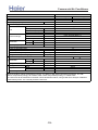
4U30HS1ERA
Piping
Outdoor unit
Function
Cooling
Heating
Rating capacity
W
8100
9800
Power input (indoor + outdoor)
W
2220
2430
Current input (indoor + outdoor)
A
9.7
10.6
EER / COP
W/W
3.65
4.03
Minimum capacity
W
1500
1800
Minimum power input
W
550
550
Maximum capacity
W
9800
10500
Maximum power input (indoor + outdoor)
W
3800
3800
Power source
1PH, 220-230V~, 50/60Hz
Max.Running current (indoor + outdoor)
A/A
16.5
16.5
Power facor(under rating power input)
99%
99%
Fuse size (recommended size)
25
A
Indoor units number
2~4
TNB220FLHMC-L / MGC
Model / Manufacture
870CC / FV50S
Oil charge and type
Compressor
Twin Rotary (DC inverter)
Type
0.88
Ω
Winding resistance(at 20℃)
Axial × 1
Fan type × Number
Max. 860
Motor speed
r/min
Fan motor model
EHDS80A100AS
Fan system
Motor type
DC
100/125
Motor output/input power
W
about 4000
Air-flows (H/M/L)
m³/h
TP2M / 7.0
Type / Diameter
mm
Heat
Number of rows
3
exchanger
about 0.75
Face area
m²
948/340/840
Dimension
External
mm
(WxDxH)
1040/430/1000
Package
mm
PMVs
Refrigerant control method
Defrosting method
Automatic by reversible cycle
Crankcase heater power
35
W
58
Noise level
H/M/L
dB(A)
76/87
Weight
Net / Shipping
kg / kg
R410A / 3.0
Type / Charge
kg
Refrigerant
m
Total liquid piping length without recharge
less than 40
20
Recharge
g/m
4* Φ6.35
Liquid
mm
Pipe size
3* Φ9.52(A,B,C)+1*Φ12.7(D)
Gas
mm
Connecting method
Flared
15
Max.Drop between IU & OU
m
7.5
Between
Max.Drop between indoor units
m
IU & OU
25
Max.Piping length between IU & OU
m
70
Max.Total length
m
1. The above performance data are from the combination of 4U30HS1ERA+4*AS09CS1ERA.
2. Large drop and long piping installation will obviously reduce the total capacity.
Norminal condition: indoor temperature (cooling): 27℃DB/19℃WB, indoor temperature (heating): 20 ℃DB
Outdoor temperature(cooling): 35℃DB/24℃WB, outdoor temperature(heating): 7 ℃DB/6℃WB
The noise level will be measured in the third octave band limited values, using a Real Time Analyser calibrated sound
intensity meter. It is a sound pressure noise level.
-8-
>_]]VbTZR\ <Zb >_^UZdZ_^Vb
Item
Model
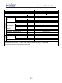
5U34HS1ERA
Piping
Outdoor unit
Function
Cooling
Heating
Rating capacity
W
10000
10700
Power input (indoor + outdoor)
W
2940
2850
Current input (indoor + outdoor)
A
12.8
12.4
EER / COP
W/W
3.4
3.75
Minimum capacity
W
1500
1800
Minimum power input
W
550
550
Maximum capacity
W
11000
11500
Maximum power input (indoor + outdoor)
W
4000
4000
Power source
1PH, 220-230V~, 50/60Hz
Max.Running current (indoor + outdoor)
A/A
17.4
17.4
Power facor(under rating power input)
99%
99%
Fuse size (recommended size)
30
A
Indoor units number
2~5
TNB220FLHMC-L / MGC
Model / Manufacture
870CC / FV50S
Oil charge and type
Compressor
Twin Rotary (DC inverter)
Type
0.88
Ω
Winding resistance(at 20 ℃)
Fan type × Number
Axial × 1
Max. 900
Motor speed
r/min
EHDS80A100AS
Fan motor model
Fan system
DC
Motor type
100/125
Motor output/input power
W
about 4000
Air-flows (H/M/L)
m³/h
TP2M / 7.0
Type / Diameter
mm
Heat
Number of rows
3
exchanger
about 0.75
Face area
m²
948/340/840
Dimension
External
mm
(WxDxH)
1040/430/1000
Package
mm
Refrigerant control method
PMVs
Automatic by reversible cycle
Defrosting method
Crankcase heater power
35
W
58/-/Noise level
H/M/L
dB(A)
77/88
Weight
Net / Shipping
kg / kg
R410A / 3.2
Type / Charge
kg
Refrigerant
less than 40
Total liquid piping length without recharge
m
20
Recharge
g/m
5* Φ6.35
Liquid
mm
Pipe size
4* Φ9.52(A,B,C,D)+1*Φ12.7(E)
Gas
mm
Connecting method
Flared
15
Max.Drop between IU & OU
m
7.5
Between
Max.Drop between indoor units
m
IU & OU
25
Max.Piping length between IU & OU
m
80
Max.Total length
m
1. The above performance data are from the combination of 5U34HS1ERA+3*AS09CS1ERA+1*AS18CS1ERA.
2. Large drop and long piping installation will obviously reduce the total capacity.
Norminal condition: indoor temperature (cooling): 27 ℃DB/19℃WB, indoor temperature (heating): 20 ℃DB
Outdoor temperature(cooling): 35℃DB/24℃WB, outdoor temperature(heating): 7 ℃DB/6℃WB
The noise level will be measured in the third octave band limited values, using a Real Time Analyser calibrated sound
intensity meter. It is a sound pressure noise level.
-9-
56
>_]]VbTZR\ <Zb >_^UZdZ_^Vb
Item
Function
Capacity
Sensible heat ratio
Dehumidifying capacity
Power Supply
Model
kW
10‐³×m³/h
AB09CS1ERA
cooling
heating
2.6
2.9
0.71
/
1.5
1PH,220-230V 50-60HZ
CENTRIFUGALX1
690/620/560
0.03
620/520/450
inner grooved pipe/φ7
0.272
2-7
570×570×260
718×680×380
PVC 26/32
Remote or Wired
PIPING
Panel
Indoor unit
Type × Number
Speed(H-M-L)
r/min
Fan
Fan motor output power
kW
Air-flow(H-M-L)
m³/h
Type / Diameter
mm
Heat exchanger Total Area
m²
Temp. scope
℃
External (L×W×H)
mm×mm×mm
Dimension
Package (L×W×H)
mm×mm×mm
Drainage pipe (material , I.D./O.D.)
mm
Control type (Remote /wired)
56
Fresh air hole dimension
mm
Electricity Heater
NONE
kW
Noise level
(H-M-L)
40/36/32
dB(A)
Weight
(Net / Shipping)
17/20
kg / kg
Panel model (color)
PB-700IB(WHITE)
700×700×60
External
(L×W×H) mm×mm×mm
Dimension
740×750×115
Package
(L×W×H) mm×mm×mm
Weight (Net / Shipping)
2.8 / 4.8
kg / kg
Type
R410A
Refrigerant
Liquid
φ6.35(1/4)
mm
Pipe
Gas
φ9.52(3/8)
mm
Connecting Method
flared
Norminal condition: indoor temperature (cooling): 27℃DB/19℃WB, indoor temperature (heating): 20℃
DB
Outdoor temperature(cooling): 35℃DB/24℃WB, outdoor temperature(heating): 7℃DB/6℃WB
The noise level will be measured in the third octave band limited values, using a Real Time Analyser
calibrated sound intensity meter. It is a sound pressure noise level.
-10-
>_]]VbTZR\ <Zb >_^UZdZ_^Vb
Item
Function
Capacity
Sensible heat ratio
Dehumidifying capacity
Power Supply
Fan
kW
10‐³×m³/h
Type × Number
Speed(H-M-L)
Fan motor output power
Air-flow(H-M-L)
Indoor unit
Static pressure
PIPING
AD09LS1ERA
Model
Type / Diameter
Total Area
Heat exchanger
Temp. scope
External (L×W×H)
Dimension
Package (L×W×H)
Drainage pipe (material , I.D./O.D.)
Control type (Remote / Wired)
Fresh air hole dimension
Electricity Heater
Noise level
(H-M-L)
Weight
(Net / Shipping)
Type
Refrigerant
Liquid
Pipe
Gas
Connecting Method
r/min
kW
m³/h
Pa
mm
m²
℃
mm×mm×mm
mm×mm×mm
mm
mm
kW
dB(A)
kg / kg
mm
mm
cooling
2.6
0.71
heating
2.9
/
1.6
1PH,220-230V 50-60HZ
CENTRIFUGALX1
1000/900/800±50
0.05
550/450/400
25
inner grooved pipe/φ7
0.11
2-7
610×483×220
695×536×265
20/24
wired
NONE
NONE
37/34/31
14/16
R410A
φ6.35(1/4)
φ9.52(3/8)
flared
Norminal condition: indoor temperature (cooling): 27℃DB/19℃WB, indoor temperature (heating): 20℃DB
Outdoor temperature(cooling): 35℃DB/24℃WB, outdoor temperature(heating): 7℃DB/6℃WB
The noise level will be measured in the third octave band limited values, using a Real Time Analyser calibrated
sound intensity meter. It is a sound pressure noise level.
-11-
>_]]VbTZR\ <Zb >_^UZdZ_^Vb
PIPING
Panel
Indoor unit
Item
Function
Capacity
Sensible heat ratio
Dehumidifying capacity
Power Supply
Type × Number
Speed(H-M-L)
Fan
Fan motor output power
Air-flow(H-M-L)
Type / Diameter
Heat exchanger
Total Area
Temp. scope
External (L×W×H)
Dimension
Package (L×W×H)
Drainage pipe (material , I.D./O.D.)
Control type (Remote /wired)
Fresh air hole dimension
Electricity Heater
Noise level
(H-M-L)
Weight
(Net / Shipping)
Panel model (color)
External (L×W×H)
Dimension
Package (L×W×H)
Weight
(Net / Shipping)
Type
Refrigerant
Liquid
Pipe
Gas
Connecting Method
Model
AB12CS1ERA
kW
10‐³×m³/h
r/min
kW
m³/h
mm
m²
℃
mm×mm×mm
mm×mm×mm
mm
mm
kW
dB(A)
kg / kg
mm×mm×mm
mm×mm×mm
kg / kg
mm
mm
cooling
3.5(0.9--4.5)
0.71
heating
3.7(1.0---4.8)
1.5
1PH,220-230V 50-60HZ
CENTRIFUGALX1
690/620/560
0.03
620/520/450
inner grooved pipe/φ7
0.272
2-7
570×570×260
718×680×380
PVC 26/32
Remote, YR-HD
56
NONE
40/36/32
18.5/23
PB-700IB(WHITE)
700×700×60
740×750×115
3.5/4.5
R410A
φ6.35(1/4)
φ9.52(3/8)
flared
Norminal condition: indoor temperature (cooling): 27℃DB/19℃WB, indoor temperature (heating): 20℃DB
Outdoor temperature(cooling): 35℃DB/24℃WB, outdoor temperature(heating): 7℃DB/6℃WB
The noise level will be measured in the third octave band limited values, using a Real Time Analyser calibrated sound
intensity meter. It is a sound pressure noise level.
-12-
>_]]VbTZR\ <Zb >_^UZdZ_^Vb
PIPING
Indoor unit
Item
Function
Capacity
Sensible heat ratio
Dehumidifying capacity
Power Supply
Model
kW
10‐³×m³/h
Type × Number
Speed(H-M-L)
r/min
Fan
Fan motor output power
kW
Air-flow(H-M-L)
m³/h
Type / Diameter
mm
Heat exchanger
Total Area
m²
Temp. scope
℃
External (L×W×H) mm×mm×mm
Dimension
Package (L×W×H) mm×mm×mm
Drainage pipe (material , I.D./O.D.)
mm
Control type (Remote /wired)
Fresh air hole dimension
mm
Electricity Heater
kW
Noise level
(H-M-L)
dB(A)
Weight
(Net / Shipping)
kg / kg
Type
Refrigerant
Liquid
mm
Pipe
Gas
mm
Connecting Method
AC12CS1ERA
cooling
heating
3.5(0.9--4.5)
3.9(1.0---4.8)
0.71
/
1.6
1PH,220-230V 50-60HZ
CENTRIFUGALX2
1100/1025/825
0.09
650/550/450
inner grooved pipe/φ7
0.20
2-7
990×655×199
1150×750×300
PVC 18/20
Remote, YR-HD
NONE
NONE
41/37/33
26.3/32.3
R410A
φ6.35(1/4)
φ9.52(3/8)
flared
Norminal condition: indoor temperature (cooling): 27℃DB/19℃WB, indoor temperature (heating): 20℃DB
Outdoor temperature(cooling): 35℃DB/24℃WB, outdoor temperature(heating): 7℃DB/6℃WB
The noise level will be measured in the third octave band limited values, using a Real Time Analyser calibrated sound
intensity meter. It is a sound pressure noise level.
-13-
>_]]VbTZR\ <Zb >_^UZdZ_^Vb
Item
Function
Capacity
Sensible heat ratio
Dehumidifying capacity
Power Supply
Fan
Model
kW
10‐³×m³/h
Type × Number
Speed(H-M-L)
Fan motor output power
Air-flow(H-M-L)
PIPING
Indoor unit
Static pressure
Type / Diameter
Total Area
Temp. scope
External (L×W×H)
Dimension
Package (L×W×H)
Drainage pipe (material , I.D./O.D.)
Control type (Remote /wired)
Fresh air hole dimension
Electricity Heater
Noise level
(H-M-L)
Weight
(Net / Shipping)
Type
Refrigerant
Liquid
Pipe
Gas
Connecting Method
Heat exchanger
r/min
kW
m³/h
Pa
mm
m²
℃
mm×mm×mm
mm×mm×mm
mm
mm
kW
dB(A)
kg / kg
mm
mm
AD12LS1ERA
cooling
heating
3.5(0.9--4.5)
4.0(1.0---4.8)
0.71
1.6
1PH,220-230V 50-60HZ
CENTRIFUGALX1
1000/900/800±50
0.05
550/450/400
25
inner grooved pipe/φ7
0.11
2-7
610×483×220
695×536×265
20/24
wired, YR-E14
NONE
NONE
37/34/31
14/16
R410A
φ6.35(1/4)
φ9.52(3/8)
flared
Norminal condition: indoor temperature (cooling): 27℃DB/19℃WB, indoor temperature (heating): 20℃DB
Outdoor temperature(cooling): 35℃DB/24℃WB, outdoor temperature(heating): 7℃DB/6℃WB
The noise level will be measured in the third octave band limited values, using a Real Time Analyser calibrated sound
intensity meter. It is a sound pressure noise level.
-14-
>_]]VbTZR\ <Zb >_^UZdZ_^Vb
PIPING
Panel
Indoor unit
Item
Function
Capacity
Sensible heat ratio
Dehumidifying capacity
Power Supply
Type × Number
Speed(H-M-L)
Fan
Fan motor output power
Air-flow(H-M-L)
Type / Diameter
Heat exchanger
Total Area
Temp. scope
External (L×W×H)
Dimension
Package (L×W×H)
Drainage pipe (material , I.D./O.D.)
Control type (Remote /wired)
Fresh air hole dimension
Electricity Heater
Noise level
(H-M-L)
Weight
(Net / Shipping)
Panel model (color)
External (L×W×H)
Dimension
Package (L×W×H)
Weight
(Net / Shipping)
Type
Refrigerant
Liquid
Pipe
Gas
Connecting Method
Model
kW
10‐³×m³/h
r/min
kW
m³/h
mm
m²
℃
mm×mm×mm
mm×mm×mm
mm
mm
kW
dB(A)
kg / kg
mm×mm×mm
mm×mm×mm
kg / kg
mm
mm
AB18CS1ERA
cooling
heating
5.0(1.8--5.8)
5.2(2.0---6.5)
0.71
/
1.8
1PH,220-230V 50-60HZ
centrifugal*1
795/690/550±50
0.065
680/620/500
inner grooved pipe/φ7
0.272
2-7
570×570×260
718×680×380
PVC 26/32
Remote, YR-HD
56
NONE
42/37/35
18.5/23
PB-700IB(WHITE)
700×700×60
740×750×115
3.5/4.5
R410A
Φ6.35
Φ12.7
FLARED
Norminal condition: indoor temperature (cooling): 27℃DB/19℃WB, indoor temperature (heating): 20℃DB
Outdoor temperature(cooling): 35℃DB/24℃WB, outdoor temperature(heating): 7℃DB/6℃WB
The noise level will be measured in the third octave band limited values, using a Real Time Analyser calibrated
sound intensity meter. It is a sound pressure noise level.
-15-
>_]]VbTZR\ <Zb >_^UZdZ_^Vb
PIPING
Indoor unit
Item
Function
Capacity
Sensible heat ratio
Dehumidifying capacity
Power Supply
AC18CS1ERA
Model
kW
10‐³×m³/h
Type × Number
Speed(H-M-L)
r/min
Fan
Fan motor output power
kW
Air-flow(H-M-L)
m³/h
Type / Diameter
mm
Total Area
Heat exchanger
m²
Temp. scope
℃
External (L×W×H) mm×mm×mm
Dimension
Package (L×W×H) mm×mm×mm
Drainage pipe (material , I.D./O.D.)
mm
Control type (Remote /wired)
Fresh air hole dimension
mm
Electricity Heater
kW
Noise level
(H-M-L)
dB(A)
Weight
(Net / Shipping)
kg / kg
Type
Refrigerant
Liquid
mm
Pipe
Gas
mm
Connecting Method
cooling
5.0(1.8--5.8)
0.71
heating
5.5(2.0---6.5)
/
1.8
1PH,220-230V 50-60HZ
CENTRIFUGALX2
1220/1190/1050
0.075
800/720/650
inner grooved pipe/φ7
0.45
2-7
990×655×199
1150×750×300
PVC 18/20
Remote, YR-HD
/
/
44/41/36
28.3/34.3
R410A
Φ6.35
Φ12.7
FLARED
Norminal condition: indoor temperature (cooling): 27℃DB/19℃WB, indoor temperature (heating): 20℃DB
Outdoor temperature(cooling): 35℃DB/24℃WB, outdoor temperature(heating): 7℃DB/6℃WB
The noise level will be measured in the third octave band limited values, using a Real Time Analyser calibrated
sound intensity meter. It is a sound pressure noise level.
-16-
>_]]VbTZR\ <Zb >_^UZdZ_^Vb
Item
Function
Capacity
Sensible heat ratio
Dehumidifying capacity
Power Supply
PIPING
Indoor unit
Fan
Model
kW
10‐³×m³/h
Type × Number
Speed(H-M-L)
Fan motor output power
Air-flow(H-M-L)
Static pressure
Type / Diameter
Total Area
Heat exchanger
Temp. scope
External (L×W×H)
Dimension
Package (L×W×H)
Drainage pipe (material , I.D./O.D.)
Control type (Remote /wired)
Noise level
(H-M-L)
Weight
(Net / Shipping)
Type
Refrigerant
Liquid
Pipe
Gas
Connecting Method
r/min
kW
m³/h
Pa
mm
m²
℃
mm×mm×mm
mm×mm×mm
mm
dB(A)
kg / kg
mm
mm
AD18LS1ERA
cooling
5.0(1.8---6.0)
0.73
heating
5.5(2.0---6.2)
/
2.1
1PH,220-230V 50-60HZ
centrifugal fan X 2
700±30 / 540±30 / 400±30
50
850/780/600
25
inner grooved pipe/φ7
0.34
2-7
1090×500×220
1174×549×294
20/24
wired, YR-E14
41/35/32
23/26.5
R410A
Φ6.35
Φ12.7
FLARED
Norminal condition: indoor temperature (cooling): 27℃DB/19℃WB, indoor temperature (heating): 20℃DB
Outdoor temperature(cooling): 35℃DB/24℃WB, outdoor temperature(heating): 7℃DB/6℃WB
The noise level will be measured in the third octave band limited values, using a Real Time Analyser calibrated
sound intensity meter. It is a sound pressure noise level.
-17-
>_]]VbTZR\ <Zb >_^UZdZ_^Vb
PIPING
Panel
Indoor unit
Item
Function
Capacity
Sensible heat ratio
Dehumidifying capacity
Power Supply
Type × Number
Speed(H-M-L)
Fan
Fan motor output power
Air-flow(H-M-L)
Type / Diameter
Heat exchanger
Total Area
Temp. scope
External (L×W×H)
Dimension
Package (L×W×H)
Drainage pipe (material , I.D./O.D.)
Control type (Remote /wired)
Fresh air hole dimension
Noise level
(H-M-L)
Weight
(Net / Shipping)
Panel model (color)
External (L×W×H)
Dimension
Package (L×W×H)
Weight
(Net / Shipping)
Type
Refrigerant
Liquid
Pipe
Gas
Connecting Method
Model
kW
10‐³×m³/h
r/min
kW
m³/h
mm
m²
℃
mm×mm×mm
mm×mm×mm
mm
mm
dB(A)
kg / kg
mm×mm×mm
mm×mm×mm
kg / kg
mm
mm
AB24ES1ERA
cooling
heating
6.5(2.0---7.3)
7.1(2.5--8.0))
0.72
/
2.5
1PH,220-230VAC,50HZ
centrifugal*1
670±40/550±50/460±50
0.16
1300/1100/870
inner grooved pipe/φ7
0.49
2-7
840*840*240
910*910*300
PVC 26/32
remote, YR-HD
none
46/43/39
26.8/32.6
PB-950JB (WHITE)
950/950/80
985/985/115
6.0/9.0
R410A
9.52
15.88
flared
Norminal condition: indoor temperature (cooling): 27℃DB/19℃WB, indoor temperature (heating): 20℃DB
Outdoor temperature(cooling): 35℃DB/24℃WB, outdoor temperature(heating): 7℃DB/6℃WB
The noise level will be measured in the third octave band limited values, using a Real Time Analyser calibrated sound
intensity meter. It is a sound pressure noise level.
-18-
>_]]VbTZR\ <Zb >_^UZdZ_^Vb
Item
Function
Capacity
Sensible heat ratio
Dehumidifying capacity
Power Supply
Model
PIPING
Indoor unit
AC24CS1ERA
cooling
heating
6.3(2.0-7.3)
7.1(2.5-8.0)
kW
0.72
/
2.0
10‐³×m³/h
1PH,220-230VAC,50HZ
Type × Number
centrifugal*2
Speed(H-M-L)
1220±40/1190±50/1050±50/980±50
r/min
Fan
Fan motor output power
0.10
kW
Air-flow(H-M-L)
800/720/650
m³/h
Type / Diameter
inner grooved pipe/φ7
mm
Heat exchanger
Total Area
0.49
m²
Temp. scope
2-7
℃
990*665*199
External (L×W×H) mm×mm×mm
Dimension
1150*750*300
Package (L×W×H) mm×mm×mm
Drainage pipe (material , I.D./O.D.)
PVC 18/20
mm
Control type (Remote /wired)
remote, YR-HD
Noise level
(H-M-L)
48/46/44
dB(A)
Weight
(Net / Shipping)
28.3/34.3
kg / kg
Type
R410A
Refrigerant
Liquid
9.52
mm
Pipe
Gas
15.88
mm
Connecting Method
flared
Norminal condition: indoor temperature (cooling): 27℃DB/19℃WB, indoor temperature (heating): 20℃DB
Outdoor temperature(cooling): 35℃DB/24℃WB, outdoor temperature(heating): 7℃DB/6℃WB
The noise level will be measured in the third octave band limited values, using a Real Time Analyser calibrated
sound intensity meter. It is a sound pressure noise level.
-19-
>_]]VbTZR\ <Zb >_^UZdZ_^Vb
PIPING
Indoor unit
Item
Model
Function
Capacity
kW
Sensible heat ratio
Dehumidifying capacity
10‐³×m³/h
Power Supply
Type × Number
Speed(H-M-L)
r/min
Fan
Fan motor output power
kW
Air-flow(H-M-L)
m³/h
Static pressure
Pa
Type / Diameter
mm
Heat exchanger Total Area
m²
Temp. scope
℃
mm×mm×mm
External
(L×W×H)
Dimension
mm×mm×mm
Package
(L×W×H)
Drainage pipe (material , I.D./O.D.)
mm
Control type (Remote /wired)
Noise level
(H-M-L)
dB(A)
Weight
(Net / Shipping)
kg / kg
Type
Refrigerant
Liquid
mm
Pipe
Gas
mm
Connecting Method
AD24LS1ERA
cooling
heating
6.8(2.0---7.6)
7.1(3.0---8.3)
0.72
/
2.2
1PH,220-230VAC,50HZ
centrifugal*2
1250±40/1130±40/1000±50/850±50
0.05
1200/1050/850(white terminal 0 Pa)
25
inner grooved pipe/φ7
0.51
2-7
1090*500*220
1174*549*294
20/24
wired, YR-E14
49/45/41/37
25.2/28.4
R410A
9.52
15.88
flared
Norminal condition: indoor temperature (cooling): 27℃DB/19℃WB, indoor temperature (heating): 20℃DB
Outdoor temperature(cooling): 35℃DB/24℃WB, outdoor temperature(heating): 7℃DB/6℃WB
The noise level will be measured in the third octave band limited values, using a Real Time Analyser calibrated sound
intensity meter. It is a sound pressure noise level.
-20-
>_]]VbTZR\ <Zb >_^UZdZ_^Vb
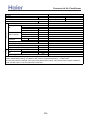
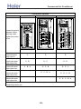
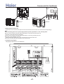
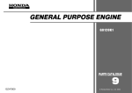
3. Dimension
3U19FS1ERA:
320
Air inlet
353
16.5
Air inlet
52
Air outlet
26
289
Handle
Handle
}
}
}
355
100
24
357
51
688
Liquid pipe:Ø6.35(flared)1/4
A unit connection
Gas pipe :Ø9.52(flared)3/8
Liquid pipe:Ø6.35(flared)1/4
Gas pipe :Ø9.52(flared)3/8 B unit connection
Liquid pipe:Ø6.35(flared)1/4
Gas pipe :Ø9.52(flared)3/8 C unit connection
116
582
146
293
813
73
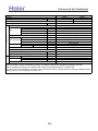
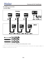
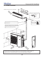
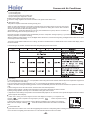
4U25HS1ERA, 4U30HS1ERA:
580
35
340
Air inlet
413
70
35
Air inlet
184
380
184
Gas pipe
Ø9.52(flared) 3/8(A,B,C unit)
Ø12.7(flared) 1/2(D unit)
Air outlet
948
6
Handle
Handle
A unit connection
315
B unit connection
537
408
45
840
Handle
Indoor and outdoor
connect wiring hole
(30*48)
340
C unit connection
D unit connection
163
50
28
21
311
Liquid pipe
Ø6.35(flared) 1/4
-21-
>_]]VbTZR\ <Zb >_^UZdZ_^Vb
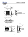
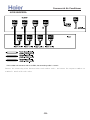
5U34HS1ERA:
580
184
35
340
Air inlet
413
70
35
Air inlet
380
184
Gas pipe
Ø9.52(flared) 3/8(A,B,C,D unit)
Ø12.7(flared) 1/2(E unit)
Air outlet
948
6
Handle
Handle
A unit connection
B unit connection
537
C unit connection
D unit connection
45
408
405
840
Handle
Indoor and outdoor
connect wiring hole
(30*48)
340
311
21
73
E unit connection
28
Liquid pipe
Ø6.35(flared) 1/4
-22-
49
>_]]VbTZR\ <Zb >_^UZdZ_^Vb
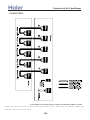
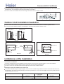
EJZZN[[N \UR[C
:;9
A9
V]NYSJWNM MRZ[JULN KN[^NNU [QN LNRSRUP
JUM [QN WJUNSC ;>TT
:>9TT
@99TT 7WJUNS MRTNUZRVU8
WJUNS
LNRSRUP
56
:A9
><>TT 7KN[^NNU Z\ZWNUZRVU WVSNZ8
OYNZQ JRY QVSN
>@9TT 7RUMVVY \UR[ MRTNUZRVU8
?>9TT 7LNRSRUP VWNURUP MRTNUZRVU8
:=9
@99TT 7WJUNS MRTNUZRVU8
HGFI D
HGFI D
:=> :99 A9
5;:?7<=8697 >:8=4
1-+
1+0
1++
22+
,++
100
/+
.0
.0
.+
-++
33+
-23-
-/+
,33
3++
<;9TT
Z\ZWNUZRVU QVSMNY
@>
>@9TT 7RUMVVY \UR[ MRTNUZRVU8
>@
SRX\RM WRWN
?>
?>9TT 7LNRSRUP VWNURUP MRTNUZRVU8
MYJRUJPN WRWN
PJZ WRWN
?9TT
B9
>_]]VbTZR\ <Zb >_^UZdZ_^Vb
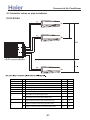
:FJKJMH DNMDFBKFE QSOF RMJQ8
U
Y
T
X
Z
W
[
V
=MPQBKKBQJNM EJLFMPJNM8+LL,
AD092LS1ERA
AD122LS1ERA
AD142LS1ERA
AD182LS1ERA
256
AD092LS1ERA
AD122LS1ERA
00.
72.
AD142LS1ERA
AD182LS1ERA
00.
-24-
\
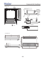
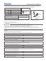
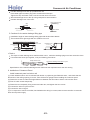
>_]]VbTZR\ <Zb >_^UZdZ_^Vb
VIEW C
Cassette type unit: AB24
VIEW D
740 (hanging position)
860~890 (ceiling hole)
VIEW A
740 (hanging position)
860~890 (ceiling hole)
VIEW B
VIEW D
VIEW C
VIEW B
over 1000
ov
er
ov
er
VIEW A
ov
er
ov
er
-25-
>_]]VbTZR\ <Zb >_^UZdZ_^Vb
4. Pipe and wiring installation
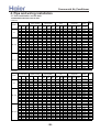
4.1 Multi combination and the data
3U19FS1ERA combination and the data
COOLING
Rated capacity(Kw)
(Nom. cooling)
Comb.
Unit Unit Unit Unit Unit Unit
A
B
C
A
B
C
7
—
—
2.0
—
—
9
—
—
2.5
—
—
1x1
12
—
—
3.5
—
—
18
—
—
5.0
—
—
24
—
—
5.4
—
—
7
7
— 2.00 2.00
—
7
9
— 2.00 2.50
—
7
12
— 1.96 3.44
—
7
18
— 1.54 3.86
—
BI (1x2)
9
9
— 2.50 2.50
—
9
12
— 2.25 3.15
—
9
18
— 1.80 3.60
—
12
12
— 2.70 2.70
—
12
18
— 2.22 3.18
—
7
7
7 1.80 1.80 1.80
7
7
9 1.66 1.66 2.08
7
7
12 1.44 1.44 2.52
7
7
18 1.20 1.20 3.00
7
9
9 1.54 1.93 1.93
TRI (1x3)
7
9
12 1.35 1.69 2.36
7
12
12 1.20 2.10 2.10
9
9
9 1.80 1.80 1.80
9
9
12 1.59 1.59 2.22
9
12
12 1.42 1.99 1.99
Combinations
total cooling
capacity(kW)
min. rated max.
data data data
1.00 2.00 2.80
1.00 2.50 3.10
1.00 3.50 4.10
1.50 5.00 5.40
1.50 5.40 6.50
1.00 4.00 4.40
1.00 4.50 4.90
1.00 5.40 5.80
1.50 5.40 7.00
1.00 5.00 7.00
1.50 5.40 7.00
1.50 5.40 7.00
1.50 5.40 7.00
1.50 5.40 7.00
1.50 5.40 7.00
1.50 5.40 7.00
1.50 5.40 7.00
1.50 5.40 7.00
1.50 5.40 7.00
1.50 5.40 7.00
1.50 5.40 7.00
1.50 5.40 7.00
1.50 5.40 7.00
1.50 5.40 7.00
total power input
(kW)
min. rated max.
data data Data
0.50 0.55 1.30
0.50 0.70 1.34
0.50 1.00 1.50
0.50 1.50 1.90
0.50 1.70 2.00
0.50 1.30 2.60
0.50 1.50 2.60
0.50 1.65 2.60
0.50 1.65 2.60
0.50 1.55 2.60
0.50 1.57 2.60
0.50 1.65 2.60
0.50 1.57 2.60
0.50 1.65 2.60
0.50 1.65 2.60
0.50 1.65 2.60
0.50 1.65 2.60
0.50 1.65 2.60
0.50 1.60 2.60
0.50 1.60 2.60
0.50 1.60 2.60
0.50 1.41 2.60
0.50 1.41 2.60
0.50 1.50 2.60
total current
(A)@230V
min. rated max.
data data Data
2.22 2.44 5.80
2.22 3.11 6.00
2.22 4.44 6.70
2.22 6.65 8.40
2.22 7.54 8.90
2.22 5.77 12.00
2.22 6.65 12.00
2.22 7.32 12.00
2.22 7.32 12.00
2.22 6.88 12.00
2.22 6.94 12.00
2.22 7.32 12.00
2.22 6.94 12.00
2.22 7.32 12.00
2.22 7.32 12.00
2.22 7.32 12.00
2.22 7.32 12.00
2.22 7.32 12.00
2.22 7.10 12.00
2.22 7.10 12.00
2.22 7.10 12.00
2.22 6.26 12.00
2.22 6.24 12.00
2.22 6.65 12.00
energy
EER
label
(W/W)
rated
capacity
3.64
A
3.57
A
3.50
A
3.33
A
3.18
B
3.08
B
3.00
B
3.27
A
3.27
A
3.23
A
3.45
A
3.27
A
3.45
A
3.27
A
3.27
A
3.27
A
3.27
A
3.27
A
3.37
A
3.37
A
3.38
A
3.83
A
3.84
A
3.60
A
total heating
capacity(KW)
min. rated max.
data data data
1.00 2.30 4.00
1.00 2.90 4.10
1.00 3.80 4.10
1.50 5.50 6.00
1.50 6.50 7.00
1.20 4.60 5.00
1.20 5.20 5.70
1.20 6.10 6.50
1.80 6.50 8.10
1.80 5.80 8.10
1.80 6.50 8.10
1.80 6.50 8.10
1.80 6.50 8.10
1.80 6.50 8.10
1.80 6.50 8.10
1.80 6.50 8.10
1.80 6.50 8.10
1.80 6.50 8.10
1.80 6.50 8.10
1.80 6.50 8.10
1.80 6.50 8.10
1.80 6.50 8.10
1.80 6.50 8.10
1.80 6.50 8.10
total power input
(W)
min. rated max.
data data Data
0.47 0.60 1.50
0.47 0.80 1.40
0.47 1.10 1.50
0.47 1.60 2.60
0.47 1.80 2.60
0.47 1.35 2.30
0.47 1.65 2.30
0.47 1.65 2.30
0.50 1.65 2.60
0.50 1.60 2.60
0.50 1.61 2.60
0.50 1.65 2.60
0.50 1.61 2.60
0.50 1.65 2.60
0.50 1.55 2.60
0.50 1.60 2.60
0.50 1.60 2.60
0.50 1.65 2.60
0.50 1.60 2.60
0.50 1.55 2.60
0.50 1.55 2.60
0.50 1.53 2.60
0.50 1.52 2.60
0.50 1.55 2.60
total current
(A)@230V
min. rated max.
data data Data
2.09 2.66 5.80
2.09 3.55 6.00
2.09 4.88 6.70
2.09 7.10 8.40
2.09 7.99 8.90
2.50 5.99 10.20
2.50 7.32 13.00
2.50 7.32 13.00
2.65 7.32 13.00
2.65 7.10 13.00
2.50 7.13 13.00
2.50 7.32 13.00
2.65 7.13 13.00
2.65 7.32 13.00
2.50 6.88 13.00
2.65 7.10 13.00
2.65 7.10 13.00
2.50 7.32 13.00
2.50 7.10 13.00
2.50 6.88 13.00
2.50 6.88 13.00
2.50 6.79 13.00
2.50 6.73 13.00
2.50 6.88 13.00
energy
EER
label
(W/W)
rated
capacity
3.83
A
3.63
A
3.45
A
3.44
A
3.61
A
3.41
B
3.15
B
3.70
A
3.94
A
3.63
A
4.04
A
3.94
A
4.04
A
3.94
A
4.19
A
4.06
A
4.06
A
3.94
A
4.06
A
4.19
A
4.19
A
4.25
A
4.28
A
4.19
A
HEATING
Rated capacity(kW)
(Nom. heating)
Comb.
Unit Unit Unit Unit Unit Unit
A
B
C
A
B
C
7
—
—
2.3
—
—
9
—
—
2.9
—
—
1x1
12
—
—
3.8
—
—
18
—
—
5.5
—
—
24
—
—
6.5
—
—
7
7
— 2.30 2.30
—
7
9
— 2.30 2.90
—
7
12
— 2.30 3.80
—
7
18
— 1.92 4.58
—
BI (1x2)
9
9
— 2.90 2.90
—
9
12
— 2.81 3.69
—
9
18
— 2.24 4.26
—
12
12
— 3.25 3.25
—
12
18
— 2.66 3.84
—
7
7
7 2.17 2.17 2.17
7
7
9 1.99 1.99 2.51
7
7
12 1.78 1.78 2.94
7
7
18 1.48 1.48 3.54
7
9
9 1.85 2.33 2.33
TRI (1x3)
7
9
12 1.66 2.09 2.74
7
12
12 1.51 2.49 2.49
9
9
9 2.17 2.17 2.17
9
9
12 1.96 1.96 2.57
9
12
12 1.80 2.35 2.35
Combinations
-26-
>_]]VbTZR\ <Zb >_^UZdZ_^Vb
QUADRI(1x4)
TRI (1x3)
BI (1x2)
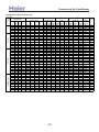
4U25HS1ERA combination and the data
COOLING
Rated capacity Output/kW
Combinations
(Nom. cooling)
Comb.
Unit Unit Unit Unit Unit Unit Unit Unit
A
B
C
D
A
B
C
D
7
—
—
—
2.0
—
—
—
9
—
—
—
2.5
—
—
—
1x1
12
—
—
—
3.5
—
—
—
18
—
—
—
5.0
—
—
—
24
—
—
—
6.5
—
—
—
7
18
—
— 2.00 5.00
—
—
7
24
—
— 1.67 5.43
—
—
9
18
—
— 2.37 4.73
—
—
9
24
—
— 1.97 5.13
—
—
12
12
—
— 3.50 3.50
—
—
12
18
—
— 3.13 4.47
—
—
12
24
—
— 2.66 4.94
—
—
18
18
—
— 3.80 3.80
—
—
18
24
—
— 3.30 4.30
—
—
7
7
9
— 2.00 2.00 2.50
—
7
7
12
— 2.00 2.00 3.50
—
7
7
18
— 1.69 1.69 4.22
—
7
7
24
— 1.45 1.45 4.70
—
7
9
9
— 2.00 2.50 2.50
—
7
9
12
— 1.90 2.38 3.33
—
7
9
18
— 1.60 2.00 4.00
—
7
12
12
— 1.69 2.96 2.96
—
7
12
18
— 1.45 2.53 3.62
—
9
9
9
— 2.50 2.50 2.50
—
9
9
12
— 2.24 2.24 3.13
—
9
9
18
— 1.90 1.90 3.80
—
9
12
12
— 2.00 2.80 2.80
—
12
12
12
— 2.53 2.53 2.53
—
12
12
18
— 2.22 2.22 3.17
—
7
7
7
7 1.90 1.90 1.90 1.90
7
7
7
9 1.79 1.79 1.79 2.24
7
7
7
12 1.60 1.60 1.60 2.80
7
7
7
18 1.38 1.38 1.38 3.45
7
7
9
9 1.69 1.69 2.11 2.11
7
7
9
12 1.52 1.52 1.90 2.66
7
9
9
9 1.60 2.00 2.00 2.00
7
9
9
12 1.45 1.81 1.81 2.53
9
9
9
9 1.90 1.90 1.90 1.90
9
9
9
12 1.73 1.73 1.73 2.42
total cooling
capacity(kW)
min. rated max.
data data data
1.00 2.00 2.80
1.00 2.50 3.10
1.00 3.50 4.10
1.50 5.00 5.40
1.50 6.50 7.40
1.00 7.00 7.40
1.00 7.10 8.50
1.00 7.10 7.90
1.00 7.10 9.00
1.00 7.00 6.80
1.00 7.60 8.40
1.00 7.60 9.00
1.00 7.60 8.60
1.00 7.60 9.00
1.20 6.50 7.10
1.20 7.50 8.10
1.20 7.60 8.80
1.20 7.60 9.00
1.20 7.00 7.10
1.20 7.60 8.60
1.20 7.60 8.80
1.20 7.60 8.60
1.20 7.60 8.80
1.20 7.50 8.10
1.20 7.60 8.60
1.20 7.60 8.80
1.20 7.60 8.60
1.20 7.60 8.50
1.20 7.60 8.50
1.50 7.60 9.00
1.50 7.60 9.00
1.50 7.60 9.00
1.50 7.60 9.00
1.50 7.60 9.00
1.50 7.60 9.00
1.50 7.60 9.00
1.50 7.60 9.00
1.50 7.60 9.00
1.50 7.60 9.00
-27-
total power input
(kW)
min. rated max.
data data Data
0.50 0.56 1.30
0.50 0.70 1.34
0.50 1.00 1.50
0.50 1.50 1.90
0.50 2.00 3.00
0.50 2.25 3.50
0.55 2.25 3.50
0.50 2.25 3.50
0.55 2.25 3.50
0.50 2.19 3.50
0.50 2.19 3.50
0.55 2.39 3.50
0.55 2.39 3.50
0.55 2.40 3.50
0.55 2.00 3.50
0.55 2.19 3.50
0.55 2.34 3.50
0.55 2.34 3.50
0.55 2.14 3.50
0.55 2.19 3.50
0.55 2.34 3.50
0.55 2.19 3.50
0.55 2.34 3.50
0.55 2.14 3.50
0.55 2.14 3.50
0.55 2.14 3.50
0.55 2.14 3.50
0.55 2.14 3.50
0.55 2.19 3.50
0.55 2.14 3.50
0.55 2.14 3.50
0.55 2.14 3.50
0.55 2.19 3.50
0.55 2.14 3.50
0.55 2.14 3.50
0.55 2.14 3.50
0.55 2.10 3.50
0.55 2.10 3.50
0.55 2.10 3.50
total current
(A)@230V
min. rated max.
data data
Data
2.22 2.48
5.80
2.22 3.11
6.00
2.22 4.44
6.70
2.22 6.65
8.40
2.22 8.87 13.20
2.15 10.87 16.80
2.50 10.87 16.80
2.15 10.87 16.80
2.50 10.87 16.80
2.15 10.57 16.80
2.15 10.57 16.80
2.50 11.53 16.80
2.50 11.53 16.80
2.50 11.58 16.80
2.50 9.66 16.80
2.50 10.57 16.80
2.50 11.29 16.80
3.50 11.29 16.80
2.50 10.32 16.80
2.50 10.57 16.80
2.50 11.29 16.80
2.50 10.57 16.80
2.50 11.29 16.80
2.50 10.32 16.80
2.50 10.32 16.80
2.50 10.32 16.80
2.50 10.32 16.80
2.50 10.32 16.80
2.50 10.57 16.80
2.85 10.32 16.80
2.85 10.32 16.80
2.85 10.32 16.80
2.85 10.57 16.80
2.85 10.32 16.80
2.85 10.32 16.80
2.85 10.32 16.80
2.85 10.13 16.80
2.85 10.13 16.80
2.85 10.13 16.80
energy
EER
label
(W/W)
rated
capacity
3.57
A
3.57
A
3.50
A
3.33
A
3.25
A
3.11
B
3.16
B
3.16
B
3.16
B
3.20
A
3.47
A
3.18
B
3.18
B
3.17
B
3.25
A
3.43
A
3.25
A
3.25
A
3.28
A
3.48
A
3.25
A
3.47
A
3.25
A
3.51
A
3.56
A
3.56
A
3.56
A
3.56
A
3.47
A
3.56
A
3.56
A
3.56
A
3.47
A
3.56
A
3.56
A
3.56
A
3.62
A
3.62
A
3.62
A
>_]]VbTZR\ <Zb >_^UZdZ_^Vb
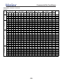
4U25HS1ERA combination and the data
HEATING
Rated capacity Output/kW
(Nom. heating)
Comb.
Unit Unit Unit Unit Unit Unit Unit Unit
A
B
C
D
A
B
C
D
7
—
—
—
2.3
—
—
—
9
—
—
—
2.9
—
—
—
1x1
12
—
—
—
3.8
—
—
—
18
—
—
—
5.5
—
—
—
24
—
—
—
7.0
—
—
—
7
18
—
— 2.30 5.50
—
—
7
24
—
— 2.13 6.47
—
—
9
18
—
— 2.90 5.50
—
—
9
24
—
— 2.52 6.08
—
—
12
12
—
— 3.80 3.80
—
—
12
18
—
— 3.51 5.09
—
—
12
24
—
— 3.03 5.57
—
—
18
18
—
— 4.30 4.30
—
—
18
24
3.78 4.82
7
7
9
— 2.30 2.30 2.90
—
7
7
12
— 2.30 2.30 3.80
—
7
7
18
— 1.96 1.96 4.68
—
7
7
24
— 1.71 1.71 5.19
—
7
9
9
— 2.30 2.90 2.90
—
7
9
12
— 2.20 2.77 3.63
—
7
9
18
— 1.85 2.33 4.42
—
7
12
12
— 2.00 3.30 3.30
—
7
12
18
— 1.71 2.82 4.08
—
9
9
9
— 2.87 2.87 2.87
—
9
9
12
— 2.60 2.60 3.40
—
9
9
18
— 2.21 2.21 4.19
—
9
12
12
— 2.38 3.11 3.11
—
12
12
12
— 2.87 2.87 2.87
—
12
12
18
— 2.49 2.49 3.61
—
7
7
7
7 2.15 2.15 2.15 2.15
7
7
7
9 2.02 2.02 2.02 2.54
7
7
7
12 1.85 1.85 1.85 3.05
7
7
7
18 1.60 1.60 1.60 3.81
7
7
9
9 1.90 1.90 2.40 2.40
7
7
9
12 1.75 1.75 2.21 2.89
7
9
9
9 1.80 2.27 2.27 2.27
7
9
9
12 1.66 2.10 2.10 2.75
9
9
9
9 2.15 2.15 2.15 2.15
9
9
9
12 2.00 2.00 2.00 2.61
QUADRI(1x4)
TRI (1x3)
BI (1x2)
Combinations
total heating
capacity(KW)
min. rated max.
data data data
1.00 2.30 4.00
1.00 2.90 4.10
1.00 3.80 4.10
1.50 5.50 6.00
1.50 7.00 8.60
1.20 7.80 8.40
1.20 8.60 9.50
1.20 8.40 9.20
1.20 8.60 9.50
1.20 7.60 8.20
1.20 8.60 9.50
1.20 8.60 9.50
1.20 8.60 9.50
1.50 8.60 9.50
1.50 7.50 8.40
1.50 8.40 9.30
1.50 8.60 9.50
1.80 8.60 9.50
1.50 8.10 9.50
1.50 8.60 9.50
1.50 8.60 9.50
1.50 8.60 9.50
1.50 8.60 9.50
1.50 8.60 9.50
1.50 8.60 9.50
1.50 8.60 9.50
1.50 8.60 9.50
1.50 8.60 9.50
1.50 8.60 9.50
1.80 8.60 9.50
1.80 8.60 9.50
1.80 8.60 9.50
1.80 8.60 9.50
1.80 8.60 9.50
1.80 8.60 9.50
1.80 8.60 9.50
1.80 8.60 9.50
1.80 8.60 9.50
1.80 8.60 9.50
-28-
total power input
(W)
min. rated max.
data data Data
0.55 0.60 1.50
0.55 0.80 1.40
0.55 1.10 1.50
0.55 1.60 2.60
0.55 1.91 2.60
0.50 2.20 3.50
0.55 2.31 3.50
0.50 2.20 3.50
0.55 2.31 3.50
0.50 2.15 3.50
0.50 2.30 3.50
0.55 2.31 3.50
0.55 2.20 3.50
0.55 2.40 3.50
0.55 2.16 3.50
0.55 2.16 3.50
0.55 2.26 3.50
0.55 2.31 3.50
0.55 2.21 3.50
0.55 2.21 3.50
0.55 2.26 3.50
0.55 2.21 3.50
0.55 2.26 3.50
0.55 2.21 3.50
0.55 2.21 3.50
0.55 2.26 3.50
0.55 2.11 3.50
0.55 2.26 3.50
0.55 2.31 3.50
0.55 2.21 3.50
0.55 2.21 3.50
0.55 2.16 3.50
0.55 2.21 3.50
0.55 2.21 3.50
0.55 2.21 3.50
0.55 2.11 3.50
0.55 2.11 3.50
0.55 2.06 3.50
0.55 2.11 3.50
total current
(A)@230V
min. rated max.
data data
Data
2.44 2.66
5.80
2.44 3.55
6.00
2.44 4.88
6.70
2.44 7.10
8.40
2.44 8.47
8.90
2.15 9.76 16.80
2.50 10.24 16.80
2.15 9.76 16.80
2.50 10.24 16.80
2.15 9.54 16.80
2.15 10.20 16.80
2.50 10.24 16.80
2.50 9.76 16.80
2.50 10.65 16.80
2.50 9.58 16.80
2.50 9.58 16.80
2.50 10.02 16.80
2.50 10.24 16.80
2.50 9.80 16.80
2.50 9.80 16.80
2.50 10.02 16.80
2.50 9.80 16.80
2.50 10.02 16.80
2.50 9.80 16.80
2.50 9.80 16.80
2.50 10.02 16.80
2.50 9.36 16.80
2.50 10.02 16.80
2.50 10.24 16.80
2.85 9.80 16.80
2.85 9.80 16.80
2.85 9.58 16.80
2.85 9.80 16.80
2.85 9.80 16.80
2.85 9.80 16.80
2.85 9.36 16.80
2.85 9.36 16.80
2.85 9.13 16.80
2.85 9.36 16.80
energy
EER
label
(W/W)
rated
capacity
3.83
A
3.63
A
3.45
A
3.44
A
3.67
A
3.55
B
3.72
A
3.82
A
3.72
A
3.53
B
3.74
A
3.72
A
3.91
A
3.58
B
3.47
B
3.89
A
3.81
A
3.72
A
3.67
A
3.89
A
3.81
A
3.89
A
3.81
A
3.89
A
3.89
A
3.81
A
4.08
A
3.81
A
3.72
A
3.89
A
3.89
A
3.98
A
3.89
A
3.89
A
3.89
A
4.08
A
4.08
A
4.18
A
4.08
A
>_]]VbTZR\ <Zb >_^UZdZ_^Vb
QUADRI(1x4)
TRI (1x3)
BI (1x2)
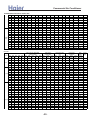
4U30HS1ERA combination and the data
COOLING
Rated capacity Output/kW
Combinations
(Nom. cooling)
Comb.
Unit Unit Unit Unit Unit Unit Unit Unit
A
B
C
D
A
B
C
D
7
—
—
—
2.0
—
—
—
9
—
—
—
2.5
—
—
—
1x1
12
—
—
—
3.5
—
—
—
18
—
—
—
5.0
—
—
—
24
—
—
—
6.5
—
—
—
7
24
1.91 6.19
9
18
2.50 5.00
9
24
2.25 5.85
12
18
3.16 4.94
12
24
2.67 5.43
18
18
4.05 4.05
18
24
3.52 4.58
24
24
4.05 4.05
7
7
18
1.80 1.80 4.50
24
7
7
1.54 1.54 5.01
7
9
12
2.00 2.50 3.50
7
9
18
1.71 2.13 4.26
24
7
9
1.47 1.84 4.79
7
12
12
1.80 3.15 3.15
7
12
18
1.54 2.70 3.86
24
7
12
1.35 2.36 4.39
9
9
9
2.50 2.50 2.50
9
9
12
2.38 2.38 3.34
9
9
18
2.03 2.03 4.05
24
9
9
1.76 1.76 4.58
9
12
12
2.13 2.98 2.98
9
12
18
1.84 2.58 3.68
24
9
12
1.62 2.27 4.21
12
12
12
2.70 2.70 2.70
12
12
18
2.36 2.36 3.38
12
12
24
2.10 2.10 3.90
12
18
18
2.10 3.00 3.00
7
7
7
7 2.00 2.00 2.00 2.00
7
7
7
9 1.91 1.91 1.91 2.38
7
7
7
12 1.71 1.71 1.71 2.98
7
7
7
18 1.47 1.47 1.47 3.68
24 1.30 1.30 1.30 4.21
7
7
7
7
7
9
9 1.80 1.80 2.25 2.25
7
7
9
12 1.62 1.62 2.03 2.84
7
7
9
18 1.41 1.41 1.76 3.52
7
7
9
24 1.25 1.25 1.56 4.05
7
7
12
12 1.47 1.47 2.58 2.58
7
7
12
18 1.30 1.30 2.27 3.24
7
9
9
9 1.71 2.13 2.13 2.13
7
9
9
12 1.54 1.93 1.93 2.70
7
9
9
18 1.35 1.69 1.69 3.38
7
9
12
12 1.41 1.76 2.47 2.47
7
12
12
12 1.30 2.27 2.27 2.27
9
9
9
9 2.03 2.03 2.03 2.03
9
9
9
12 1.84 1.84 1.84 2.58
9
9
12
12 1.69 1.69 2.36 2.36
9
9
12
18 1.50 1.50 2.10 3.00
9
12
12
12 1.56 2.18 2.18 2.18
12
12
12
12 2.03 2.03 2.03 2.03
total cooling
capacity(kW)
min. rated max.
data data data
1.00 2.00 2.80
1.00 2.50 3.10
1.00 3.50 4.10
1.50 5.00 5.40
1.50 6.50 7.40
1.00 8.10 9.80
1.00 7.50 9.80
1.00 8.10 9.80
1.00 8.10 9.80
1.00 8.10 9.80
1.00 8.10 9.80
1.00 8.10 9.80
1.00 8.10 9.80
1.50 8.10 9.80
1.50 8.10 9.80
1.50 8.00 9.80
1.50 8.10 9.80
1.50 8.10 9.80
1.50 8.10 9.80
1.50 8.10 9.80
1.50 8.10 9.80
1.50 7.50 9.80
1.50 8.10 9.80
1.50 8.10 9.80
1.50 8.10 9.80
1.50 8.10 9.80
1.50 8.10 9.80
1.50 8.10 9.80
1.50 8.10 9.80
1.50 8.10 9.80
1.50 8.10 9.80
1.50 8.10 9.80
1.50 8.00 9.80
1.50 8.10 9.80
1.50 8.10 9.80
1.50 8.10 9.80
1.50 8.10 9.80
1.50 8.10 9.80
1.50 8.10 9.80
1.50 8.10 9.80
1.50 8.10 9.80
1.50 8.10 9.80
1.50 8.10 9.80
1.50 8.10 9.80
1.50 8.10 9.80
1.50 8.10 9.80
1.50 8.10 9.80
1.50 8.10 9.80
1.50 8.10 9.80
1.50 8.10 9.80
1.50 8.10 9.80
1.50 8.10 9.80
1.50 8.10 9.80
1.50 8.10 9.80
-29-
total power input
(kW)
min. rated max.
data data Data
0.50 0.56 1.30
0.50 0.70 1.34
0.50 1.00 1.50
0.50 1.50 1.90
0.50 2.00 3.00
0.55 2.60 3.80
0.55 2.40 3.80
0.55 2.50 3.80
0.55 2.40 3.80
0.55 2.50 3.80
0.55 2.40 3.80
0.55 2.50 3.80
0.55 2.60 3.80
0.55 2.40 3.80
0.55 2.50 3.80
0.55 2.30 3.80
0.55 2.40 3.80
0.55 2.50 3.80
0.55 2.40 3.80
0.55 2.40 3.80
0.55 2.50 3.80
0.55 2.30 3.80
0.55 2.35 3.80
0.55 2.40 3.80
0.55 2.50 3.80
0.55 2.40 3.80
0.55 2.40 3.80
0.55 2.50 3.80
0.55 2.40 3.80
0.55 2.40 3.80
0.55 2.45 3.80
0.55 2.50 3.80
0.55 2.25 3.80
0.55 2.25 3.80
0.55 2.25 3.80
0.55 2.40 3.80
0.55 2.50 3.80
0.55 2.25 3.80
0.55 2.25 3.80
0.55 2.40 3.80
0.55 2.45 3.80
0.55 2.25 3.80
0.55 2.40 3.80
0.55 2.25 3.80
0.55 2.28 3.80
0.55 2.40 3.80
0.55 2.30 3.80
0.55 2.30 3.80
0.55 2.22 3.80
0.55 2.25 3.80
0.55 2.25 3.80
0.55 2.30 3.80
0.55 2.35 3.80
0.55 2.35 3.80
total current
(A)@230V
min. rated max.
data data
Data
2.22 2.48
5.80
2.22 3.11
6.00
2.22 4.44
6.70
2.22 6.65
8.40
2.22 8.87 13.20
2.15 11.54 17.90
2.15 10.65 17.90
2.15 11.09 17.90
2.15 10.65 17.90
2.15 11.09 17.90
2.15 10.65 17.90
2.15 11.09 17.90
2.15 11.54 17.90
2.50 10.65 17.90
2.50 11.09 17.90
2.50 10.20 17.90
2.50 10.65 17.90
2.50 11.09 17.90
2.50 10.65 17.90
2.50 10.65 17.90
2.50 11.09 17.90
2.50 10.20 17.90
2.50 10.43 17.90
2.50 10.65 17.90
2.50 11.09 17.90
2.50 10.65 17.90
2.50 10.65 17.90
2.50 11.09 17.90
2.50 10.65 17.90
2.50 10.65 17.90
2.50 10.87 17.90
2.50 11.09 17.90
2.85 9.98 17.90
2.85 9.98 17.90
2.85 9.98 17.90
2.85 10.65 17.90
2.85 11.09 17.90
2.85 9.98 17.90
2.85 9.98 17.90
2.85 10.65 17.90
2.85 10.87 17.90
2.85 9.98 17.90
2.85 10.65 17.90
2.85 9.98 17.90
2.85 10.12 17.90
2.85 10.65 17.90
2.85 10.20 17.90
2.85 10.20 17.90
2.85 9.85 17.90
2.85 9.98 17.90
2.85 9.98 17.90
2.85 10.20 17.90
2.85 10.43 17.90
2.85 10.43 17.90
energy
EER
label
(W/W)
rated
capacity
3.57
A
3.57
A
3.50
A
3.33
A
3.25
A
3.12
B
3.13
B
3.24
A
3.37
A
3.24
A
3.38
A
3.24
A
3.12
B
3.38
A
3.24
A
3.48
A
3.37
A
3.24
A
3.38
A
3.37
A
3.24
A
3.26
A
3.44
A
3.38
A
3.24
A
3.37
A
3.37
A
3.24
A
3.38
A
3.37
A
3.31
A
3.24
A
3.56
A
3.60
A
3.60
A
3.37
A
3.24
A
3.60
A
3.60
A
3.37
A
3.31
A
3.60
A
3.38
A
3.60
A
3.55
A
3.37
A
3.52
A
3.52
A
3.65
A
3.60
A
3.60
A
3.52
A
3.45
A
3.45
A
>_]]VbTZR\ <Zb >_^UZdZ_^Vb
4U30HS1ERA combination and the data
HEATING
Rated capacity Output/kW
(Nom. heating)
Comb.
Unit Unit Unit Unit Unit Unit Unit Unit
A
B
C
D
A
B
C
D
7
—
—
—
2.3
—
—
—
9
—
—
—
2.9
—
—
—
1x1
12
—
—
—
3.8
—
—
—
18
—
—
—
5.5
—
—
—
24
—
—
—
7.0
—
—
—
7
24
2.30 7.00
9
18
2.90 5.50
9
24
2.87 6.93
12
18
3.80 5.50
12
24
3.45 6.35
18
18
4.90 4.90
18
24
4.31 5.49
24
24
4.90 4.90
7
7
18
2.23 2.23 5.34
24
7
7
1.94 1.94 5.91
7
9
12
2.30 2.90 3.80
7
9
18
2.11 2.66 5.04
24
7
9
1.85 2.33 5.62
7
12
12
2.28 3.76 3.76
7
12
18
1.94 3.21 4.65
24
7
12
1.72 2.84 5.24
9
9
9
2.90 2.90 2.90
9
9
12
2.90 2.90 3.80
9
9
18
2.52 2.52 4.77
24
9
9
2.22 2.22 5.36
9
12
12
2.71 3.55 3.55
9
12
18
2.33 3.05 4.42
24
9
12
2.07 2.72 5.01
12
12
12
3.27 3.27 3.27
12
12
18
2.84 2.84 4.11
12
12
24
2.55 2.55 4.70
12
18
18
2.52 3.64 3.64
7
7
7
7 2.30 2.30 2.30 2.30
7
7
7
9 2.30 2.30 2.30 2.90
7
7
7
12 2.11 2.11 2.11 3.48
7
7
7
18 1.82 1.82 1.82 4.35
24 1.62 1.62 1.62 4.94
7
7
7
7
7
9
9 2.17 2.17 2.73 2.73
7
7
9
12 1.99 1.99 2.52 3.30
7
7
9
18 1.73 1.73 2.19 4.15
7
7
12
12 1.85 1.85 3.05 3.05
7
7
12
18 1.62 1.62 2.68 3.88
7
9
9
9 2.05 2.58 2.58 2.58
7
9
9
12 1.89 2.39 2.39 3.13
7
9
9
18 1.66 2.09 2.09 3.96
7
9
12
12 1.76 2.22 2.91 2.91
7
12
12
12 1.65 2.72 2.72 2.72
9
9
9
9 2.45 2.45 2.45 2.45
9
9
9
12 2.27 2.27 2.27 2.98
9
9
12
12 2.12 2.12 2.78 2.78
9
9
12
18 1.88 1.88 2.47 3.57
9
12
12
12 1.99 2.60 2.60 2.60
12
12
12
12 2.45 2.45 2.45 2.45
QUADRI(1x4)
TRI (1x3)
BI (1x2)
Combinations
total heating
capacity(KW)
min. rated max.
data data data
1.00 2.30 4.00
1.00 2.90 4.10
1.00 3.80 4.10
1.50 5.50 6.00
1.50 7.00 8.60
1.20 9.30 10.50
1.20 8.40 10.50
1.20 9.80 10.50
1.20 9.30 10.50
1.20 9.80 10.50
1.20 9.80 10.50
1.20 9.80 10.50
1.20 9.80 10.50
1.20 9.80 10.50
1.50 9.80 10.50
1.50 9.00 10.50
1.50 9.80 10.50
1.50 9.80 10.50
1.50 9.80 10.50
1.50 9.80 10.50
1.50 9.80 10.50
1.50 8.70 10.50
1.50 9.60 10.50
1.50 9.80 10.50
1.50 9.80 10.50
1.50 9.80 10.50
1.50 9.80 10.50
1.50 9.80 10.50
1.50 9.80 10.50
1.50 9.80 10.50
1.50 9.80 10.50
1.50 9.80 10.50
1.50 9.20 10.50
1.50 9.80 10.50
1.80 9.80 10.50
1.80 9.80 10.50
1.80 9.80 10.50
1.80 9.80 10.50
1.80 9.80 10.50
1.80 9.80 10.50
1.80 9.80 10.50
1.80 9.80 10.50
1.80 9.80 10.50
1.80 9.80 10.50
1.80 9.80 10.50
1.80 9.80 10.50
1.80 9.80 10.50
1.80 9.80 10.50
1.80 9.80 10.50
1.80 9.80 10.50
1.80 9.80 10.50
1.80 9.80 10.50
1.80 9.80 10.50
-30-
total power input
(W)
min. rated max.
data data Data
0.55 0.60 1.50
0.55 0.80 1.40
0.55 1.10 1.50
0.55 1.60 2.60
0.55 1.80 2.60
0.50 2.60 3.80
0.50 2.60 3.80
0.50 2.70 3.80
0.50 2.60 3.80
0.50 2.70 3.80
0.50 2.60 3.80
0.50 2.70 3.80
0.50 2.75 3.80
0.55 2.60 3.80
0.55 2.70 3.80
0.55 2.60 3.80
0.55 2.60 3.80
0.55 2.70 3.80
0.55 2.70 3.80
0.55 2.60 3.80
0.55 2.70 3.80
0.55 2.20 3.80
0.55 2.70 3.80
0.55 2.43 3.80
0.55 2.70 3.80
0.55 2.70 3.80
0.55 2.60 3.80
0.55 2.70 3.80
0.55 2.58 3.80
0.55 2.60 3.80
0.55 2.65 3.80
0.55 2.75 3.80
0.55 2.38 3.80
0.55 2.70 3.80
0.55 2.60 3.80
0.55 2.60 3.80
0.55 2.70 3.80
0.55 2.60 3.80
0.55 2.60 3.80
0.55 2.60 3.80
0.55 2.60 3.80
0.55 2.60 3.80
0.55 2.60 3.80
0.55 2.60 3.80
0.55 2.70 3.80
0.55 2.50 3.80
0.55 2.50 3.80
0.55 2.43 3.80
0.55 2.50 3.80
0.55 2.50 3.80
0.55 2.55 3.80
0.55 2.60 3.80
0.55 2.60 3.80
total current
(A)@230V
min. rated max.
data data
Data
2.44 2.66
5.80
2.44 3.55
6.00
2.44 4.88
6.70
2.44 7.10
8.40
2.44 7.99
8.90
2.15 11.54 15.00
2.15 11.54 15.00
2.15 11.98 15.00
2.15 11.54 15.00
2.15 11.98 15.00
2.15 11.54 15.00
2.15 11.98 15.00
2.44 12.20 15.00
2.50 11.54 15.00
2.50 11.98 15.00
2.50 11.54 15.00
2.50 11.54 15.00
2.50 11.98 15.00
2.50 11.98 15.00
2.50 11.54 15.00
2.50 11.98 15.00
2.50 9.76 15.00
2.50 11.98 15.00
2.50 10.78 15.00
2.50 11.98 15.00
2.50 11.98 15.00
2.50 11.54 15.00
2.50 11.98 15.00
2.50 11.45 15.00
2.50 11.54 15.00
2.50 11.76 15.00
2.50 12.20 15.00
2.85 10.56 15.00
2.85 11.98 15.00
2.85 11.54 15.00
2.85 11.54 15.00
2.85 11.98 15.00
2.85 11.54 15.00
2.85 11.54 15.00
2.85 11.54 15.00
2.85 11.54 15.00
2.85 11.54 15.00
2.85 11.54 15.00
2.85 11.54 15.00
2.85 11.98 15.00
2.85 11.09 15.00
2.85 11.09 15.00
2.85 10.79 15.00
2.85 11.09 15.00
2.85 11.09 15.00
2.85 11.31 15.00
2.85 11.54 15.00
2.85 11.54 15.00
energy
EER
label
(W/W)
rated
capacity
3.83
A
3.63
A
3.45
A
3.44
A
3.89
A
3.58
B
3.23
C
3.63
A
3.58
B
3.63
A
3.77
A
3.63
A
3.56
B
3.77
A
3.63
A
3.46
B
3.77
A
3.63
A
3.63
A
3.77
A
3.63
A
3.95
A
3.56
B
4.03
A
3.63
A
3.63
A
3.77
A
3.63
A
3.80
A
3.77
A
3.70
A
3.56
B
3.87
A
3.63
A
3.77
A
3.77
A
3.63
A
3.77
A
3.77
A
3.77
A
3.77
A
3.77
A
3.77
A
3.77
A
3.63
A
3.92
A
3.92
A
4.03
A
3.92
A
3.92
A
3.84
A
3.77
A
3.77
A
>_]]VbTZR\ <Zb >_^UZdZ_^Vb
5U34HS1ERA combination and the data
COOLING
Combinations
Comb.
1x1
BI (1x2)
TRI (1x3)
QUADRI
(1x4)
Rated capacity Output/kW
(Nom. cooling)
Unit
Unit
Unit
Unit
Unit
A
B
C
D
E
total cooling
capacity(kW)
min.
rated
max.
data
data
data
total power input
(kW)
min. rated max.
data data Data
total current
(A)@230V
min.
rated
max.
data
data
Data
energy
EER
label
(W/W)
rated
capacity
Unit
A
Unit
B
Unit
C
Unit
D
Unit
E
7
9
12
18
24
—
—
—
—
—
—
—
—
—
—
—
—
—
—
—
—
—
—
—
—
2.0
2.5
3.5
5.0
6.5
—
—
—
—
—
—
—
—
—
—
—
—
—
—
—
—
—
—
—
—
1.00
1.00
1.00
1.50
1.50
2.00
2.50
3.50
5.00
6.50
2.80
3.10
4.10
5.40
7.40
0.50
0.50
0.50
0.50
0.50
0.65
0.80
1.04
1.50
2.00
1.30
1.34
1.50
1.90
3.00
2.20
2.20
2.20
2.20
2.20
2.88
3.55
4.61
6.65
8.87
5.80
6.00
6.70
8.40
13.20
3.08
3.13
3.37
3.33
3.25
B
B
A
A
A
7
18
—
—
—
2.00
5.00
—
—
—
1.00
7.00
7.50
0.50
2.30
4.00
2.15
10.20
19.00
3.04
B
7
24
—
—
—
2.00
6.50
—
—
—
1.00
8.50
9.00
0.50
2.80
4.00
2.15
12.42
19.00
3.04
B
9
18
—
—
—
2.50
5.00
—
—
—
1.00
7.50
8.00
0.50
2.40
4.00
2.15
10.65
19.00
3.13
B
9
24
—
—
—
2.50
6.50
—
—
—
1.00
9.00
9.50
0.50
2.70
4.00
2.15
11.98
19.00
3.33
A
12
18
—
—
—
3.50
5.00
—
—
—
1.00
8.50
9.00
0.50
2.70
4.00
2.15
11.98
19.00
3.15
B
12
24
—
—
—
3.50
6.50
—
—
—
1.00
10.00
10.50
0.50
3.10
4.00
2.15
13.75
19.00
3.23
A
18
18
—
—
—
5.00
5.00
—
—
—
1.00
10.00
10.50
0.50
3.10
4.00
2.15
13.75
19.00
3.23
A
18
24
—
—
—
4.35
5.65
—
—
—
1.00
10.00
10.50
0.50
3.10
4.00
2.15
13.75
19.00
3.22
A
24
24
5.00
5.00
1.00
10.00
10.50
0.50
3.20
4.00
2.15
14.20
19.00
3.13
B
7
7
12
—
—
2.00
2.00
3.50
—
—
1.50
7.50
8.10
0.55
2.74
4.00
2.50
12.16
19.00
2.74
D
7
7
18
—
—
2.00
2.00
5.00
—
—
1.50
9.00
9.80
0.55
2.74
4.00
2.50
12.16
19.00
3.28
A
7
7
24
—
—
1.90
1.90
6.19
—
—
1.50
10.00
10.50
0.55
2.74
4.00
2.50
12.16
19.00
3.65
A
7
9
9
—
—
2.00
2.50
2.50
—
—
1.50
7.00
7.60
0.55
2.74
4.00
2.50
12.16
19.00
2.55
E
7
9
12
—
—
2.00
2.50
3.50
—
—
1.50
8.00
8.60
0.55
2.74
4.00
2.50
12.16
19.00
2.92
C
7
9
18
—
—
2.00
2.50
5.00
—
—
1.50
9.50
10.20
0.55
2.74
4.00
2.50
12.16
19.00
3.47
A
7
9
24
—
—
1.82
2.27
5.91
—
—
1.50
10.00
10.50
0.55
3.04
4.00
2.50
13.49
19.00
3.29
A
7
12
12
—
—
2.00
3.50
3.50
—
—
1.50
9.00
9.60
0.55
3.04
4.00
2.50
13.49
19.00
2.96
C
7
12
18
—
—
1.90
3.33
4.76
—
—
1.50
10.00
10.50
0.55
3.04
4.00
2.50
13.49
19.00
3.29
A
7
12
24
—
—
1.67
2.92
5.42
—
—
1.50
10.00
10.50
0.55
3.04
4.00
2.50
13.49
19.00
3.29
A
9
9
9
—
—
2.50
2.50
2.50
—
—
1.50
7.50
8.10
0.55
3.04
4.00
2.50
13.49
19.00
2.47
E
9
9
12
—
—
2.50
2.50
3.50
—
—
1.50
8.50
9.10
0.55
3.04
4.00
2.50
13.49
19.00
2.80
D
9
9
18
—
—
2.50
2.50
5.00
—
—
1.50
10.00
10.50
0.55
3.04
4.00
2.50
13.49
19.00
3.29
A
9
9
24
—
—
2.17
2.17
5.65
—
—
1.50
10.00
10.50
0.55
3.04
4.00
2.50
13.49
19.00
3.29
A
9
12
12
—
—
2.50
3.50
3.50
—
—
1.50
9.50
10.20
0.55
3.04
4.00
2.50
13.49
19.00
3.13
B
9
12
18
—
—
2.27
3.18
4.55
—
—
1.50
10.00
10.50
0.55
3.04
4.00
2.50
13.49
19.00
3.29
A
9
12
24
—
—
2.00
2.80
5.20
—
—
1.50
10.00
10.50
0.55
3.04
4.00
2.50
13.49
19.00
3.29
A
12
12
12
—
—
3.33
3.33
3.33
—
—
1.50
10.00
10.50
0.55
3.04
4.00
2.50
13.49
19.00
3.29
A
12
12
18
—
—
2.92
2.92
4.17
—
—
1.50
10.00
10.50
0.55
2.99
4.00
2.50
13.27
19.00
3.34
A
12
12
24
2.59
2.59
4.81
1.50
10.00
11.00
0.55
3.27
4.00
2.50
14.51
19.00
3.06
B
12
18
18
2.59
3.70
3.70
1.50
10.00
11.00
0.55
3.27
4.00
2.50
14.51
19.00
3.06
B
18
18
18
3.33
3.33
3.33
1.80
10.00
11.00
0.55
3.32
4.00
2.50
14.73
19.00
3.01
B
7
7
7
2.00
2.00
2.00
1.80
8.00
8.80
0.55
2.89
4.00
2.50
12.82
19.00
2.77
D
7
—
2.00
—
7
7
7
9
—
2.00
2.00
2.00
2.50
—
1.80
8.50
9.30
0.55
2.89
4.00
2.50
12.82
19.00
2.94
C
7
7
7
12
—
2.00
2.00
2.00
3.50
—
1.80
9.50
10.30
0.55
2.96
4.00
2.50
13.13
19.00
3.21
A
7
7
7
18
—
1.82
1.82
1.82
4.55
—
1.80
10.00
11.00
0.55
2.99
4.00
2.50
13.27
19.00
3.34
A
7
7
7
24
—
1.60
1.60
1.60
5.20
—
1.80
10.00
11.00
0.55
2.99
4.00
2.50
13.27
19.00
3.34
A
7
7
9
9
—
2.00
2.00
2.50
2.50
—
1.80
9.00
9.80
0.55
2.96
4.00
2.50
13.13
19.00
3.04
B
7
7
9
12
—
2.00
2.00
2.50
3.50
—
1.80
10.00
10.50
0.55
2.96
4.00
2.50
13.13
19.00
3.38
A
7
7
9
18
—
1.74
1.74
2.17
4.35
—
1.80
10.00
11.00
0.55
2.99
4.00
2.50
13.27
19.00
3.34
A
7
7
9
24
—
1.54
1.54
1.92
5.00
—
1.80
10.00
11.00
0.55
2.99
4.00
2.50
13.27
19.00
3.34
A
7
7
12
12
—
1.82
1.82
3.18
3.18
—
1.80
10.00
10.80
0.55
2.96
4.00
2.50
13.13
19.00
3.38
A
7
7
12
18
—
1.60
1.60
2.80
4.00
—
1.80
10.00
11.00
0.55
2.99
4.00
2.50
13.27
19.00
3.34
A
7
9
9
9
—
2.00
2.50
2.50
2.50
—
1.80
9.50
10.30
0.55
2.96
4.00
2.50
13.13
19.00
3.21
A
7
9
9
12
—
1.90
2.38
2.38
3.33
—
1.80
10.00
10.80
0.55
2.99
4.00
2.50
13.27
19.00
3.34
A
7
9
9
18
—
1.67
2.08
2.08
4.17
—
1.80
10.00
11.00
0.55
2.99
4.00
2.50
13.27
19.00
3.34
A
-31-
>_]]VbTZR\ <Zb >_^UZdZ_^Vb
5U34HS1ERA combination and the data
QUIN
(1×5)
7
9
12
12
—
1.74
2.17
3.04
3.04
—
1.80
10.00
10.80
0.55
2.96
4.00
2.50
13.13
19.00
3.38
A
7
12
12
12
—
1.60
2.80
2.80
2.80
—
1.80
10.00
11.00
0.55
2.96
4.00
2.50
13.13
19.00
3.38
A
9
9
9
9
—
2.50
2.50
2.50
2.50
—
1.80
10.00
11.00
0.55
3.01
4.00
2.50
13.35
19.00
3.32
A
9
9
9
12
—
2.27
2.27
2.27
3.18
—
1.80
10.00
11.00
0.55
2.96
4.00
2.50
13.13
19.00
3.38
A
9
9
9
18
—
2.00
2.00
2.00
4.00
—
1.80
10.00
11.00
0.55
2.94
4.00
2.50
13.04
19.00
3.40
A
9
9
12
12
—
2.08
2.08
2.92
2.92
—
1.80
10.00
11.00
0.55
2.96
4.00
2.50
13.13
19.00
3.38
A
9
12
12
12
—
1.92
2.69
2.69
2.69
—
1.80
10.00
11.00
0.55
2.96
4.00
2.50
13.13
19.00
3.38
A
12
12
12
12
2.50
2.50
2.50
2.50
1.80
10.00
11.00
0.55
2.97
4.00
2.50
13.18
19.00
3.37
A
7
7
7
7
7
2.00
2.00
2.00
2.00
2.00
2.00
10.00
11.00
0.55
3.01
4.00
2.50
13.35
19.00
3.32
A
7
7
7
7
9
1.90
1.90
1.90
1.90
2.38
2.00
10.00
11.00
0.55
2.99
4.00
2.50
13.27
19.00
3.34
A
7
7
7
7
12
1.74
1.74
1.74
1.74
3.04
2.00
10.00
11.00
0.55
2.97
4.00
2.50
13.18
19.00
3.37
A
7
7
7
9
9
1.82
1.82
1.82
2.27
2.27
2.00
10.00
11.00
0.55
2.96
4.00
2.50
13.13
19.00
3.38
A
7
7
7
9
12
1.67
1.67
1.67
2.08
2.92
2.00
10.00
11.00
0.55
2.97
4.00
2.50
13.18
19.00
3.37
A
7
7
7
12
12
1.54
1.54
1.54
2.69
2.69
2.00
10.00
11.00
0.55
3.01
4.00
2.50
13.35
19.00
3.32
A
7
7
9
9
9
1.74
1.74
2.17
2.17
2.17
2.00
10.00
11.00
0.55
3.06
4.00
2.50
13.58
19.00
3.27
A
7
7
9
9
12
1.60
1.60
2.00
2.00
2.80
2.00
10.00
11.00
0.55
3.06
4.00
2.50
13.58
19.00
3.27
A
7
9
9
9
9
1.67
2.08
2.08
2.08
2.08
2.00
10.00
11.00
0.55
3.09
4.00
2.50
13.71
19.00
3.24
A
9
9
9
9
9
2.00
2.00
2.00
2.00
2.00
2.00
10.00
11.00
0.55
3.06
4.00
2.50
13.58
19.00
3.27
A
9
9
9
9
12
1.85
1.85
1.85
1.85
2.59
2.00
10.00
11.00
0.55
3.12
4.00
2.50
13.84
19.00
3.20
A
9
9
9
12
12
1.72
1.72
1.72
2.41
2.41
2.00
10.00
11.00
0.55
3.12
4.00
2.50
13.84
19.00
3.20
A
HEATING
Combinations
Comb.
1x1
BI (1x2)
TRI (1x3)
Rated capacity Output/kW
(Nom. heating)
Unit
Unit
Unit
Unit
Unit
A
B
C
D
E
total heating
capacity(KW)
min.
rated
max.
data
data
data
total power input
(W)
min. rated max.
data data Data
total current
(A)@230V
min.
rated
max.
data
data
Data
Unit
A
Unit
B
Unit
C
Unit
D
Unit
E
7
9
12
18
24
—
—
—
—
—
—
—
—
—
—
—
—
—
—
—
—
—
—
—
—
2.3
2.9
3.8
5.5
7.0
—
—
—
—
—
—
—
—
—
—
—
—
—
—
—
—
—
—
—
—
1.00
1.00
1.00
1.50
1.50
2.30
2.90
3.80
5.50
7.00
4.00
4.10
4.10
6.00
8.60
0.50
0.50
0.50
0.55
0.55
0.66
0.86
1.16
1.66
2.06
1.50
1.40
1.50
2.60
2.60
2.22
2.22
2.22
2.44
2.44
7
18
—
—
—
2.30
5.50
—
—
—
1.20
7.80
7.80
0.50
2.20
4.00
2.15
7
24
—
—
—
2.30
7.00
—
—
—
1.20
9.30
9.30
0.50
2.80
4.00
2.15
9
18
—
—
—
2.90
5.50
—
—
—
1.20
8.40
8.40
0.50
2.40
4.00
2.15
9
24
—
—
—
2.90
7.00
—
—
—
1.20
9.90
9.90
0.50
2.70
4.00
2.15
12
18
—
—
—
4.37
6.33
—
—
—
1.20
10.70
9.30
0.50
2.90
4.00
12
24
—
—
—
3.76
6.94
—
—
—
1.20
10.70
10.80
0.50
2.90
18
18
—
—
—
5.35
5.35
—
—
—
1.20
10.70
11.00
0.50
18
24
—
—
—
4.71
5.99
—
—
—
1.20
10.70
11.50
0.50
24
24
5.35
5.35
1.20
10.70
11.50
7
7
12
—
—
2.30
2.30
3.80
—
—
1.50
8.40
7
7
18
—
—
2.30
2.30
5.50
—
—
1.50
7
7
24
—
—
2.12
2.12
6.46
—
—
1.50
7
9
9
—
—
2.30
2.90
2.90
—
—
1.50
7
9
12
—
—
2.30
2.90
3.80
—
—
1.50
9.00
9.00
0.55
2.51
4.00
2.50
7
9
18
—
—
2.30
2.90
5.50
—
—
1.50
10.70
10.70
0.55
2.96
4.00
2.50
7
9
24
—
—
2.02
2.54
6.14
—
—
1.50
10.70
11.50
0.55
3.01
4.00
2.50
7
12
12
—
—
2.30
3.80
3.80
—
—
1.50
9.90
9.90
0.55
2.71
4.00
7
12
18
—
—
2.12
3.51
5.07
—
—
1.50
10.70
11.50
0.55
3.11
7
12
24
—
—
1.88
3.10
5.72
—
—
1.50
10.70
11.50
0.55
9
9
9
—
—
2.90
2.90
2.90
—
—
1.50
8.70
8.70
0.55
9
9
12
—
—
2.90
2.90
3.80
—
—
1.50
9.60
9.60
0.55
2.61
4.00
2.50
9
9
18
—
—
2.75
2.75
5.21
—
—
1.50
10.70
11.00
0.55
3.01
4.00
2.50
9
9
24
—
—
2.42
2.42
5.85
—
—
1.50
10.70
11.50
0.55
3.01
4.00
2.50
9
12
12
—
—
2.90
3.80
3.80
—
—
1.50
10.50
10.50
0.55
3.01
4.00
9
12
18
—
—
2.54
3.33
4.82
—
—
1.50
10.70
11.50
0.55
3.01
4.00
5.80
6.00
6.70
8.40
8.90
3.48
3.37
3.28
3.31
3.40
9.76
19.00
3.55
B
12.42
19.00
3.32
C
10.65
19.00
3.50
B
11.98
19.00
3.67
A
2.15
12.87
19.00
3.69
A
4.00
2.15
12.87
19.00
3.69
A
2.90
4.00
2.15
12.87
19.00
3.69
A
2.90
4.00
2.15
12.87
19.00
3.69
A
0.50
3.00
4.00
2.44
13.31
19.00
3.57
B
8.40
0.55
2.51
4.00
2.50
11.14
19.00
3.35
C
10.10
10.10
0.55
2.76
4.00
2.50
12.24
19.00
3.66
A
10.70
11.50
0.55
2.96
4.00
2.50
13.13
19.00
3.61
A
8.10
8.10
0.55
2.51
4.00
2.50
11.14
19.00
3.23
C
11.14
19.00
3.59
B
13.13
19.00
3.61
A
13.35
19.00
3.55
B
2.50
12.02
19.00
3.65
A
4.00
2.50
13.80
19.00
3.44
B
3.01
4.00
2.50
13.35
19.00
3.55
B
2.56
4.00
2.50
11.36
19.00
3.40
C
11.58
19.00
3.68
A
13.35
19.00
3.55
B
13.35
19.00
3.55
B
2.50
13.35
19.00
3.49
B
2.50
13.35
19.00
3.55
B
-32-
2.93
3.82
5.15
7.36
9.14
energy
EER
label
(W/W)
rated
capacity
A
A
A
A
A
>_]]VbTZR\ <Zb >_^UZdZ_^Vb
5U34HS1ERA combination and the data
QUADRI
(1x4)
QUIN
(1×5)
9
12
24
—
—
2.26
2.97
5.47
—
—
1.50
10.70
11.50
0.55
3.01
4.00
2.50
13.35
19.00
3.55
B
12
12
12
—
—
3.57
3.57
3.57
—
—
1.50
10.70
11.50
0.55
3.01
4.00
2.50
13.35
19.00
3.55
B
12
12
18
—
—
3.10
3.10
4.49
—
—
1.50
10.70
11.50
0.55
3.01
4.00
2.50
13.35
19.00
3.55
B
12
12
24
2.78
2.78
5.13
1.80
10.70
11.50
0.55
3.10
4.00
2.50
13.75
19.00
3.45
B
12
18
18
2.75
3.98
3.98
1.80
10.70
11.50
0.55
3.10
4.00
2.50
13.75
19.00
3.45
B
18
18
18
3.57
3.57
3.57
1.80
10.70
11.50
0.55
3.15
4.00
2.50
13.98
19.00
3.40
C
7
7
7
7
—
2.30
2.30
2.30
2.30
—
1.80
9.20
9.20
0.55
2.87
4.00
2.50
12.73
19.00
3.21
C
7
7
7
9
—
2.30
2.30
2.30
2.90
—
1.80
9.80
9.80
0.55
2.87
4.00
2.50
12.73
19.00
3.41
B
7
7
7
12
—
2.30
2.30
2.30
3.80
—
1.80
10.70
10.70
0.55
2.87
4.00
2.50
12.73
19.00
3.73
A
7
7
7
18
—
1.98
1.98
1.98
4.75
—
1.80
10.70
11.50
0.55
2.87
4.00
2.50
12.73
19.00
3.73
A
7
7
7
24
—
1.77
1.77
1.77
5.39
—
1.80
10.70
11.50
0.55
2.87
4.00
2.50
12.73
19.00
3.73
A
7
7
9
9
—
2.30
2.30
2.90
2.90
—
1.80
10.40
10.40
0.55
2.87
4.00
2.50
12.73
19.00
3.62
A
7
7
9
12
—
2.18
2.18
2.75
3.60
—
1.80
10.70
11.50
0.55
2.87
4.00
2.50
12.73
19.00
3.73
A
7
7
9
18
—
1.89
1.89
2.39
4.53
—
1.80
10.70
11.50
0.55
2.87
4.00
2.50
12.73
19.00
3.73
A
7
7
9
24
—
1.70
1.70
2.14
5.17
—
1.80
10.70
11.50
0.55
2.87
4.00
2.50
12.73
19.00
3.73
A
7
7
12
12
—
2.02
2.02
3.33
3.33
—
1.80
10.70
11.50
0.55
2.87
4.00
2.50
12.73
19.00
3.73
A
7
7
12
18
—
1.77
1.77
2.93
4.23
—
1.80
10.70
11.50
0.55
2.87
4.00
2.50
12.73
19.00
3.73
A
7
9
9
9
—
2.24
2.82
2.82
2.82
—
1.80
10.70
11.50
0.55
2.87
4.00
2.50
12.73
19.00
3.73
A
7
9
9
12
—
2.07
2.61
2.61
3.42
—
1.80
10.70
11.50
0.55
2.90
4.00
2.50
12.87
19.00
3.69
A
7
9
9
18
—
1.81
2.28
2.28
4.33
—
1.80
10.70
11.50
0.55
2.87
4.00
2.50
12.73
19.00
3.73
A
7
9
12
12
—
1.92
2.42
3.18
3.18
—
1.80
10.70
11.50
0.55
2.87
4.00
2.50
12.73
19.00
3.73
A
7
12
12
12
—
1.80
2.97
2.97
2.97
—
1.80
10.70
11.50
0.55
2.88
4.00
2.50
12.78
19.00
3.71
A
9
9
9
9
—
2.68
2.68
2.68
2.68
—
1.80
10.70
11.50
0.55
2.92
4.00
2.50
12.95
19.00
3.66
A
9
9
9
12
—
2.48
2.48
2.48
3.25
—
1.80
10.70
11.50
0.55
2.87
4.00
2.50
12.73
19.00
3.73
A
9
9
9
18
—
2.19
2.19
2.19
4.14
—
1.80
10.70
11.50
0.55
2.85
4.00
2.50
12.64
19.00
3.75
A
9
9
12
12
—
2.32
2.32
3.03
3.03
—
1.80
10.70
11.50
0.55
2.87
4.00
2.50
12.73
19.00
3.73
A
—
—
9
12
12
12
12
12
12
12
7
7
7
7
7
7
7
7
2.17
2.84
2.84
2.84
2.68
2.68
2.68
2.68
7
2.14
2.14
2.14
2.14
9
2.03
2.03
2.03
2.03
1.80
10.70
11.50
0.55
2.87
4.00
2.50
12.73
19.00
3.73
A
1.80
10.70
11.50
0.55
2.91
4.00
2.50
12.91
19.00
3.68
A
2.14
1.80
10.70
11.50
0.55
2.92
4.00
2.50
12.95
19.00
3.66
A
2.56
1.80
10.70
11.50
0.55
2.91
4.00
2.50
12.91
19.00
3.68
A
A
7
7
7
7
12
1.89
1.89
1.89
1.89
3.13
1.80
10.70
11.50
0.55
2.90
4.00
2.50
12.87
19.00
3.69
7
7
7
9
9
1.94
1.94
1.94
2.44
2.44
1.80
10.70
11.50
0.55
2.90
4.00
2.50
12.87
19.00
3.69
A
7
7
7
9
12
1.81
1.81
1.81
2.28
2.99
1.80
10.70
11.50
0.55
2.89
4.00
2.50
12.82
19.00
3.70
A
7
7
7
12
12
1.70
1.70
1.70
2.80
2.80
1.80
10.70
11.50
0.55
2.90
4.00
2.50
12.87
19.00
3.69
A
7
7
9
9
9
1.85
1.85
2.33
2.33
2.33
1.80
10.70
11.50
0.55
2.87
4.00
2.50
12.73
19.00
3.73
A
7
7
9
9
12
1.73
1.73
2.19
2.19
2.86
1.80
10.70
11.50
0.55
2.91
4.00
2.50
12.91
19.00
3.68
A
7
9
9
9
9
1.77
2.23
2.23
2.23
2.23
1.80
10.70
11.50
0.55
2.92
4.00
2.50
12.95
19.00
3.66
A
9
9
9
9
9
2.14
2.14
2.14
2.14
2.14
1.80
10.70
11.50
0.55
2.87
4.00
2.50
12.73
19.00
3.73
A
9
9
9
9
12
2.01
2.01
2.01
2.01
2.64
1.80
10.70
11.50
0.55
2.92
4.00
2.50
12.95
19.00
3.66
A
9
9
9
12
12
1.90
1.90
1.90
2.49
2.49
1.80
10.70
11.50
0.55
3.26
4.00
2.50
14.46
19.00
3.28
C
-33-
>_]]VbTZR\ <Zb >_^UZdZ_^Vb
4.2. Wiring connection
3U19FS1ERA
If this outdoor unit connects with AS*S1ERA, the connecting cable is 1.5mm2
Connect the connecting wires between indoor and outdoor units
terminals
match with each other.
-34-
and ensure the sequence numbers on
>_]]VbTZR\ <Zb >_^UZdZ_^Vb
4U25-30HS1ERA
If this outdoor unit connects with AS*S1ERA, the connecting cable is 1.5mm2
Connect the connecting wires between indoor and outdoor units
terminals
match with each other.
-35-
and ensure the sequence numbers on
>_]]VbTZR\ <Zb >_^UZdZ_^Vb
5U34HS1ERA:
If this outdoor unit connects with AS*S1ERA, the connecting cable is 1.5mm2
Connect the connecting wires between indoor and outdoor units
terminals
match with each other.
-36-
and ensure the sequence numbers on
>_]]VbTZR\ <Zb >_^UZdZ_^Vb
4.3 Limitation values on pipe installation
3U19FS1ERA
Item
Unit Description
Standard Maximum
A,B,C liquid pipe
mm Size of the liquid side connection pipe
φ6.35
A,B,C Gas pipe
mm Size of the gas side connection pipe
φ9.52
/
L1 (one way)
m
Max.piping length between IU and OU of the way
≤10
≤25
L2 (one way)
m
Max.piping length between IU and OU of the way
≤10
≤25
L3 (one way)
m
Max.piping length between IU and OU of the way
≤10
≤25
L1+L2+L3
m
Total liquid piping length
Drop between every two indoor units when the location of
the outdoor unit is among indoor units
Drop between every two indoor units when the location of
the outdoor unit is at one side of indoor units
≤30
≤50
≤1
≤15
≤1
≤7.5
Drop between the outdoor unit and the indoor unit
≤5
≤15
m
h
m
H+
m
m
Hm
Drop between the outdoor unit and the indoor unit when the
≤5
location of outdoor unit is among the indoor units
Drop between the outdoor unit and the indoor unit when the
≤5
location of outdoor unit is at one side of indoor units
-37-
/
≤7.5
≤15
>_]]VbTZR\ <Zb >_^UZdZ_^Vb
4U25-30HS1ERA
Item
Unit Description
Standard Maximum
A,B,C, Dliquid pipe mm Size of the liquid side connection pipe
φ6.35
/
A,B,C Gas pipe
mm Size of the gas side connection pipe
φ9.52
/
D Gas pi[pe
mm Size of the gas side connection pipe
φ12.7
/
L1 (one way)
m
Max.piping length between IU and OU of the way
≤10
≤25
L2 (one way)
m
Max.piping length between IU and OU of the way
≤10
≤25
L3 (one way)
m
Max.piping length between IU and OU of the way
≤10
≤25
L4 (one way)
m
Max.piping length between IU and OU of the way
≤10
≤25
L1+L2+L3+L4
m
Total liquid piping length
Drop between every two indoor units when the location of
the outdoor unit is among indoor units
Drop between every two indoor units when the location of
the outdoor unit is at one side of indoor units
≤40
≤70
≤1
≤15
≤1
≤7.5
Drop between the outdoor unit and the indoor unit
≤5
≤15
m
h
m
H+
m
m
Hm
Drop between the outdoor unit and the indoor unit when the
≤5
location of outdoor unit is among the indoor units
Drop between the outdoor unit and the indoor unit when the
≤5
location of outdoor unit is at one side of indoor units
-38-
≤7.5
≤15
>_]]VbTZR\ <Zb >_^UZdZ_^Vb
5U34HS1ERA:
Uni
Description
t
A,B,C,D,E liquid pipe mm Size of the liquid side connection pipe
Item
A,B,C,D Gas pipe
Standard Maximum
mm Size of the gas side connection pipe
φ6.35
/
φ9.52
/
E Gas pi[pe
mm Size of the gas side connection pipe
φ12.7
/
L1 (one way)
m
Max.piping length between IU and OU of the way
≤10
≤25
L2 (one way)
m
Max.piping length between IU and OU of the way
≤10
≤25
L3 (one way)
m
Max.piping length between IU and OU of the way
≤10
≤25
L4 (one way)
m
Max.piping length between IU and OU of the way
≤10
≤25
L5 (one way)
m
Max.piping length between IU and OU of the way
≤10
≤25
L1+L2+L3+L4+L5
m
Total liquid piping length
Drop between every two indoor units when the location of
the outdoor unit is among indoor units
Drop between every two indoor units when the location of
the outdoor unit is at one side of indoor units
≤40
≤80
≤1
≤15
≤1
≤7.5
≤5
≤15
m
h
m
H+
m
m
Hm
Drop between the outdoor unit and the indoor unit
Drop between the outdoor unit and the indoor unit when the
≤5
location of outdoor unit is among the indoor units
Drop between the outdoor unit and the indoor unit when the
≤5
location of outdoor unit is at one side of indoor units
-39-
≤7.5
≤15
>_]]VbTZR\ <Zb >_^UZdZ_^Vb
Connection cautions
model
3U19FS1ERA
4U25HS1ERA,4U30HS1ERA
5U34HS1ERA
connection priority
between indoor
and stop valve
higher from down
to up
when there is 1
D
indoor,the prior
C
E
stop valve is
when there are 2
D、C
indoors,the prior
C、B
E、D
stop valves are
when there are 3
D、C、B
indoors,the prior
C、B、A
E、D、C
stop valves are
when there are 4
D、C、B、A
indoors,the prior
E、D、C、B
stop valves are
when there are 5
indoors,the prior
E、D、C、B、A
stop valves are
Note: For better oil return and more reliable system, please execute as the above when
connecting indoor unit.
-39-
>_]]VbTZR\ <Zb >_^UZdZ_^Vb
Installation figure please refers to 4U25HS1ERA.
e
or
M
an
th
More than 5cm
4.4 Outdoor installation
cm
10
Arrangement of piping directions
Rear left
Rear right
Left
Right
Below
Attention must be
paid to the rising
up of drain hose
Wrap the insulation pipe with the finishing tape
from bottom to top.
Cut thermal insulation pipe to an appropriate
length and wrap it with tape, making sure that no
gap is left in the insulation pipe's cut line.
cm
n 10
e tha
mor
mo
re t
han
10c
m
m
0c
n6
ha
t
re
mo
mo
re
tha
n2
5c
m
If there is the danger of the unit falling or overturning, fix the unit with foundation bolts, or with wire or other means.
If the location does not have good drainage, place the unit on a level mounting base(or a plastic pedestal).
Install the outdoor unit in a level position. Failure to do so may result in water leakage or accumulation.
-40-
>_]]VbTZR\ <Zb >_^UZdZ_^Vb
20
Check the strength and level of the installation ground so that the unit will not cause any operating vibration or noise after installed.
In accordance with the foundation drawing in fix the unit securely by means of the foundation bolts.(Prepare four sets of M8 or M10
foundation bolts, nuts and washers each which are available on the market.)
It is best to screw in the foundation bolts until their length are 20mm from the foundation surface.
Outdoor Unit Installation Guideline
Where a wall or other obstacle is in the path of outdoor unit's intake or exhaust airflow, follow the installation guidelines below.
For any of the below installation pattems, the wall height on the exhaust side should be 1200mm or less.
Wall facing one side
More than 50
More than 300
1200 or
less
Side view
Wall facing two sides
Wall facing three sides
More than 150
More
More
than 100 than 300
More
than 50
More
than 100
More
than 50
Side view
More than 300
Side view
Limitations on the installation
1.Precautions on installation
Check the strength and level of the installation ground so that unit will not cause any operating vibration or noise after installation.
In accordance with the foundation drawing in fix the unit securely by means of the foundation bolts.
It is best to screw in the foundation bolts unit their length are 20 mm from the foundation surface.
2.Selecting a location for installation of the indoor units
The maxinum allowable length of refrigerant piping, and the maxmum allowable height difference between the outdoor and indoor units,
are listed below. (The shorter the refrigerant piping, the better the performance. Connect so that the piping is as short as possible. Shortest
allowable length per room is 3m)
3U19FS1ERA
4U25HS1ERA
4U30HS1ERA
5U34HS1ERA
Piping to each indoor unit
25m max.
25m max.
25m max.
Total length of piping between al lunits
50m max.
70m max.
80m max.
Outdoor unit capacity class
-41-
>_]]VbTZR\ <Zb >_^UZdZ_^Vb
Indoor Unit
Outdoor Unit
Level
difference:
15m max.
Level
difference:
15m max.
Outdoor Unit
Level
difference:
7.5m max.
Level
difference:
7.5m max.
Indoor Unit
If the outdoor unit is positioned higher than the indoor units.
If the outdoor unit is positioned higher than the indoor units.
(If lower than one or more indoor units.)
Refrigerant piping work
1. Installing outdoor unit
1) When installing the outdoor unit, refer to "Precautions for Selecting the Location" and the "Indoor/Outdoor Unit Installation Drawings".
2)If drain work is necessary, follow the procedures below.
2. Drain work
1) Use drain plug for drainage.
2) If the drain port is covered by a mounting base or floor surface, place additional foot bases of at least 30mm in height under the
outdoor unit's feet.
3) In cold areas, do not use a drain hose with the outdoor unit.(Otherwise, drain water may freeze, impairing heating performance.)
Hose
Drain elbow
Hose
Drain elbow
-42-
>_]]VbTZR\ <Zb >_^UZdZ_^Vb
3. Refrigerant piping work
1). Align the centres of both flares and tighten the flare nuts 3 or 4 turns by hand. Then tighten them fully with the tor wrenches.
Use torque wrenches when tightening the flare nuts to prevent damage to the flare nuts and escaping gas.
Flare nut fightening torque
Flare nut for
6.35
14.2-17.2N.m(144-175kgf.cm)
Flare nut for
9.52
32.7-39.9N.m(333-407kgf.cm)
Flare nut for
12.7
49.5-60.3N.m(505-615kgf.cm)
Flare nut for
15.88 61.8-75.4N.m(630-769kgf.cm)
Valve cap tightening torque
Liquid pipe 26.5-32.3N.m(270-330kgf.cm)
Coat here with refrigeration oil
Torque spanner
Spanner
Service port cap tightening torque
Pipe joint
10.8-14.7N.m(110-150kgf.cm)
Gas pipe 48.1-59.7N.m(490-610kgf.cm)
Cone nut
2)To prevent gas leakage, apply refrigeration oil on both inner and outer surfaces of the flare. (Use refrigeration oil for R410A)
4. Purging air and checking gas leakage
When piping work is completed, it is necessary to purge the air and check for gas leakage.
WARNING
1) Do not mix any substance other than the specified refrigerant (R410A) into the refrigeration cycle.
2) When refrigerant gas leaks occur, ventilate the room as soon and as much as possible.
3) R410A, as well as other refrigerants, should always be recovered and never be released directly into the environment.
4) Use a vacuum pump for R410A exclusively. Using the same vacuum pump for different refrigerents may damage the vacuun pump
or the unit.
If using additional refrigerant, perform air purging from the refrigerant pipes and indoor unit using a vacuum pump, then charge additional
refrigerant.
Use a hexagonal wrench (4mm) to operate the stop valve rod.
All refrigerant pipe joints should be tightened with a torque wrench at the specified tightening torque.
Connect projection side of charging hose(Which comes from gauge manifold) to gas stop valve's service port.
Fully open gauge manifold's low-pressure valve(Lo) and completely close its high-pressure valve(Hi).
(High-pressure valve subsequently requires no operation.)
Apply vacuum pumping. Check that the compound pressure gauge reads-0.1MPa(-76cmHg).
Evacuation for at lease 1 hour is recommended.
Close gauge manifold's low-pressure valve(Lo) and stop vacuum pump.
(Leave as is for 4-5 minutes and make sure the coupling meter needie does not go back.
If it does go back, this may indicate the presence of moisture or leaking from connecting parts. After inspecting all the connection and
loosening then retightening thenuts, reqeat steps 2-4. )
Remove covers from liquid stop valve and gas stop valve.
Turn the liquid stop valve's rod 90 degrees counterclockwise with a hexagonal wrench to open valve.
Close it after 5 seconds, and check for gas leakage.
Using soapy water, check for gas leakage from indoor unit's flare and outdoor unit's flare and valve rods.
After the check is complete, wipe all soapy water off.
Disconnect charging hose from gas stop valve's service port, then fully open liquid and gas stop valves.
(Do not attempt to turn valve rodj beyond its stop.)
Tighten valve caps and service port caps for the liquid and gas stop valves with a torque wrench at the specified torques. See "3
Refrigerant piping " on page 6 for details.
-43-
>_]]VbTZR\ <Zb >_^UZdZ_^Vb
5. Refilling the refrigerant
Check the type of refrigerant to be used on the machine namiplate.
Precautions when adding R410A
Fill from the liquid pipe in liquid form.
It is a mixed refrigerant, so adding it in gas form may cause the refrigerant composition to change, preventing normal operation.
1) Before filling, check whether the cylinder has a siphon attached or not.(It should have something like "liquid filling siphon attached"
displayed on it.)
Filling a cylinder with an attached siphon
Filling other cylinders
Stand the cylinder upright when filling.
Turn the cylinder upside-down
when filing.
There is a siphon pipe inside, so the
cylinder need not be upside-down
to fill with liquid.
2) Be sure to use the R410A tools to ensure pressure and to prevent foreign objects entering.
6. Charging with refrigerant
1) This system must use refrigersant R410A.
2) Add refrigerant 20g per meter when the total piping length
exceeds the standard value, but make sure that the total liquid
piping length should be less than the max. value.
Notes:
1) When using this product, you need not to set the address. But the L/N wires between indoor & outdoor units must be corresponded,
or there will be communication failure.
2) Quiet Operation Setting. Set the DIP "8" to ON position of SW5, the system will run with lower noise, but the max. capacity will also
reduce slightly.
3) Do not change the settings of other switchs, wrong settings can make the system damage or other malfunctions.
7.Precautions for Laying Refrigerant Piping
Cautions on pipe handling
1) Protect the open end of the pipe against dust and moisture.
2) All pipe bends should be as gentle as possible. Use a pipe bender for bending.(Bending radius should be 30 to 40mm or larger.)
Selection of copper and heat insulation materials
When using commercial copper pipes and fittings, observe the following :
1) Insulation material: Polyethylene foam
o
Heat transfer rate: 0.041 to 0.052W/mK(0.035to 0.045kcal/mh C)
o
Refrigerant gas pipe's surface temperature reaches 110 C max.
Choose heat insulation materials that will withstand this temperature.
2) Be sure to insulate both the gas and liquid piping and to provide insulation dimensions as below.
-44-
Gas pipe
Gas pipe insulation
O.D.:9.52mm,12.7mm
Thickness:0.8mm
I.D.:12-15mm,12.7mm
Thickness:13mm min.
Liquid pipe
Liquid pipe insulation
O.D.:6.35mm
Thickness:0.8mm
I.D.:18-10mm
Thickness:10mm min.
>_]]VbTZR\ <Zb >_^UZdZ_^Vb
3) Use separate thermal insulation pipes for gas and liquid refrigerant
pipe.
Inter unit wiring
Gas pipe
Wall
Be sure to
place a cap.
Liquid pipe
Rain
If no flare cap is
available, cover the
flare mouth with tape
to keep dirt or water
out.
Liquid pipe
insulation
Gas pipe
insulation
Finishing tape
Drain hose
Check
Flare's inner
surface must be
flaw-free.
The pipe end
must be evenly
flared in a perfect
circle.
Cut exactly at right
angles.
Remove burrs
Make sure that the
flare nut is fitted.
Set exactly at the position shown below.
A
Flare tool for R410A
Flare tooling die
Conventional flare tool
Clutch-type
Clutch-type(Rigid-type)
Wing-nuttype(Imperial-type)
0-0.5mm
1.0-1.5mm
1.5-2.0mm
8.Cutting and Flaring work of piping
Pipe cutting is carried out with a pipe cutter and burs must be
removed.
After inserting the flare nut, flaring work is carried out.
A
Flare tooling die
Pipe
Pipe diameter
Liquid side
Gas side
Correct
Size A (mm)
6.35mm(1/4")
0.8~1.5
9.52mm(3/8")
1.0~1.5
12.7mm(1/2")
1.0~1.5
Incorrect
Lean Damage of flare Crack
Partial
9. On drainage
Please install the drain hose so as to be downward slope without fail. Please don't do the drainage as shown below.
Less than
5cm
It becomes high
midway.
The end is immersed
in water
It waves.
It gap with the ground its
too small.
There is the bad
smell from a ditch.
Please pour water in the drain pan of the indoor unit, and confirm that drainage is carried out serely to outdoor.
In case that the attached drain hose is in a room, please apply heat insulation to it without fail.
WARNING
1) Do not use mineral oil on flared part.
2) Prevent mineral oil from getting into the system as this would educe the lifetime of the units.
3) Never use piping which has been used for previous installations. Only use parts which are delivered with the unit.
4) Do never install a drier to this R410A unit in order to guarantee its lifetime.
5) The drying material may dissolve and damage the system.
6) Incom;ete flaring may cause refrigerant gas leakage.
-45-
Too outside
>_]]VbTZR\ <Zb >_^UZdZ_^Vb
In order to protect the environment, be sure to pump down when relocating or disposing of the unit.
1) Remove the valve caps from liquid stop valve and gas stop valve.
2) Carry out forced cooling operation.
3) After five to ten minutes, close the liquid stop valve with a hexagonal wrench.
4) After two to three minutes, close the gas stop vaile and stop forced cooling
operation.
liquid
stop valve
Hexagonal
wernch
Close
Gas
stop valve
Valve cap
1. Electric wiring
The air conditioner must use special circuit , and wiring by the qualified electrician according to the wiring rules specified in national
standard.
The grounding wire and the neutral wire shall be strictly separated. Connect the neutral wire with grounding wire is incorrect.
The electric leakage breaker must be installed.
All the electric wire must be copper wire.Power supply: 1PH, 220-230V~, 50/60Hz.
The wiring method of power line is Y connection. If the power line is damaged, in order to avoid risk of electric shock, it must be replaced
by the manufacturer or its repair center or other similar qualified person.The connecting cable must be shielded.
Fuse: T3.15A 250VAC T16A 250VAC (Please check with the outdoor unit wiring diagram.)
Please check the circuit diagram about the fuse replaced.
2. Wiring method
Wiring method of orbicular terminals
For the connection wire with orbicular terminals, its wiring method is as shown in
the right figure: remove the connecting screw, put the screw through the ring on
the end of the wire, then connect to the terminal block and fasten screw.
Wiring method of straight terminals.
For the connection wire without orbicular terminals, its wiring method is: loosen
the connection screw, and insert the end of the connection wire completely into
the Terminal block, then fasten the screw.
Slightly pull the wire outwards to confirm it is firmly held.
Wiring Method for
Ring Terminal Block
Crimp connection method for wires without terminals
Connect the wire with
same diameter to the
two sides of the terminal
Do not connect the
wire with same diameter
to the same side
Wrong Pressing
Correct Pressing
Do not connect the
wire with different
diameters
Terminal
block
Pressing
Clamps
Crimp connection method for connection wire
After connection,the wire must be fastened by wire cover. The wire cover shall press on the protection
coat of the connection wire,as shown in right top figure.
Note:When connecting the wiring,confirm the terminal number of indoor and outdoor units carefully.
Incorrect wiring will damage the controller of air conditioner or the unit can not operate.
3. Wiring method of outdoor unit:
Power line
Remove the repair board of the outdoor unit and loosen the wire cover A,then put the live wire, neutral wire and grounding wire through
the wire cover ,and connect them to terminal block correspon dingly. After connection, fasten wire cover to its previous state.
Communication wire of indoor unit.
Loosen wire cover , put the communication wire through the wire cover B, and connect them to terminal block correspondingly. After
connection, fasten wire cover B to its previous state.
Note: Power line and communication wire are provided by consumers themselves.
-46-
>_]]VbTZR\ <Zb >_^UZdZ_^Vb
Wire cover A
Wire cover A Wire cover C Terminal block
Wire cover C
Wire cover B
Wire cover B
Terminal block
Valve cover
–¨
25.40
Wire cover D
Wire cover E
Valve cover
0
4. Wiring method of indoor unit
Loosen wire cover and connect the power line and communication wire of indoor unit to the terminal correspondingly.
Note:
When connecting power line to power supply terminal, please pay attention to the following items:
Do not connect the power line with different dimensions to the same connection wire end.
Improper contact will cause heat generation.
Do not connect the power line with different dimensions to the same grounding wire end.
Improper contact will affect protection.
Do not connect the power line to the connecting end of communication wire.
Incorrect connection will cause damage to the connected unit.
5. Example wiring diagram.
Wiring diagram please refers to 4U30HS1ERA
YCZ-A001
YCZ-A003
-47-
>_]]VbTZR\ <Zb >_^UZdZ_^Vb
Before starting the test running, please confirm the following works have been done successfully.
1) Correct piping work;
2) Correct wiring work;
3) Correct match of indoor and outdoor unit;
4) Proper recharge of refrigerant if needed.
Make sure that all the stop valves are fully open.
Check the voltage supplied to the outdoor and indoor units, please cinfirm that is 230V.
Wiring Error Check
This product is capable of automatic checking of wiring error.
CN2
Switch on all the 4 dip-switches on the outdoor unit small service PC-board as shown on the right. Then power
off the unit and power on again, the system will enter the operation of "Wiring Error Check". After 3 minutes
stand-by, the unit starts for automatic wiring checking.
Approximately 30 ~ 50minutes (depends on how many units installed in the system) after the unit starts, the
Errors of the wiring will be shown by the LEDs (1 to 5).
CN3
SW1
ON
CN4
1234
CN1
1
2
3
4
5
During this operation, the digital-number will alternately show the compressor working frequency (e.g. 50 stands for the current running
frequency) and letter "CH"(means checking).
After this operation, if all the wiring is correct, the digital-number will show "0", if there has wrong wiring, the digital-number will show "EC"(error
connection) and also it will flashing.
The service monitor LEDs indicate the error of wiring, as shown in the table below. For details about how to read the LED display, refer to
the service manual.
If self-checking is not possible, check the indoor unit wiring and piping in the usual manner.
Status
Test running.
1) If the temperature is lower than 16 OC, it is impossible to test cooling with remote controller, and also when the temperature is higher than
30 OC, it is impossible to test heating.
2) To test cooling, set the lowest temperature at 16 OC. To test heating,set the highest temperature, at 30 OC.
3) Please check both cooling and heating operation of each unit individually and then also check the simultaneous operation of all indoor
units.
4) After ruuning the unit for about 20 minutes, check the indoor unit outlet temperature.
5) After the unit is stopped, or working mode changed, the system will not start again for about 3 minutes.
6) During cooling operation, frost may ocur on the indoor unit or pipes, this is normal.
7) Operate the unit according to the operation manual. Please kindly explain to our customers how to operate through the instruction manual.
Seven-segment numeric display
1) When unit is runing, this seven-segment numeric will display the frequency of compressor. For
example,
means compressor running frequency is 40 Hz,
means compressor running
frequency is 108Hz.
2) When faulty happens, seven-segment numeric will flash and display some numbers, this number is
failure code. For example, a flashing
means No.32 failure, that is indoor and outdoor communication
error.
CN2
CN3
SW1
ON
CN4
1234
CN1
1
2
3
4
5
Communication LED
5 green LED means 5 indoor units. If one LED keep lighting that means the corresponding indoor unit has good communication with outdoor
unit. If one LED is not lighting, that means there is no communication between indoor and outdoor.
-48-
>_]]VbTZR\ <Zb >_^UZdZ_^Vb
4.5. Cassette type AB***ERA
Vilmaggamfji ^jjgl
30Jjop]hh]pekj pkkho
Uda ejop]hh]pekj pkkho heopa` ej pda
bkhhksejc odaap _]j ^a qoa` ]o namqena`0
30 T_nas `neran
40 I]_go]s
,8- Qh]_a opnkjc ajkqcd pk oqllknp pda qjep saecdp0
,9- Ok atlajoera ]npe_hao oq_d ]o pahareoekj ]j` le]jk ^ahks
ej`kkn qjep0
,:- Fjkqcd ol]_a bkn i]ejpaj]j_a0
,;- Qh]_a ikna pd]j 3i ]s]u bnki pahareoekj ]j` n]`ek pk ]rke`
`eopqn^ejc pahareoekj ]j` n]`ek0
,32- F]ou bkn i]ejpaj]j_a0
I
60 Jjjan dat]ckj ol]jjan.odebpejc
ol]jjan
2053i
50 Enehh sepd ] `e]iapan kb 82ii
70 Tl]jjan ,36. 39. 3;.46.49ii80 Qela _qppan
Ben kqphap
90 Qela atl]j`an
307i
:0 Ljeba
330 C]j` p]la
340 T_n]lan
307i
407i Pran
40Jjop]hh]pekj Qnal]n]pekj
,3- Qkoepekj kb _aehejc klajejc ^apsaaj qjep ]j` oqolaj`ejc
^khp ,bnkjp reas kb qjep-0
Q]npo O]ia
B
B`daoera p]la
C
Qela _h]il
D
Dkjja_pejc dkoa
E
En]ej]ca dkoa
F
Okj/du`nko_kle_
da]p ejoqh]pejc i]pane]h
Jj`kkn qjep 792ii
Daehejc klajejc 872ii
Pnj]iajp l]jah 922ii
Pranh]l ^apsaaj _aehejc ]j`
knj]iajp l]jah od]hh ^a 47ii
Tqolaj`ejc ^khpo
Vilmaggamfji [kjbdcnkdl
30Taha_pekj kb Jjop]hh]pekj Qh]_a
,3- Qh]_a ]^kra pda _aehejc sdana d]ra ajkqcd
ol]_a pk ]nn]jca pda qjep0
,4- Qh]_a sdana pda `n]ej]ca lela _]j ^a
]nn]jca` sahh0
,5- Qh]_a sdana ejhap ]j` kqphap ]en kb ej`kkn
]j` kqp`kkn qjep sehh jkp ^a ^hk_ga`0
,6- Ek jkp atlkoa pda qjep pk pda lh]_a sepd
da]ru keh kn ikeopqna ,a0c0gep_daj ]j`
skngodkl-0
,7- Ek jkp oap pda qjep ej pda lh]_a sdana
`aopnq_pera c]o ,oq_d ]o oqhbqne_ ]_e` c]o- kn
lqjcajp c]o ,pdejjan ]j` c]okheja_kj_ajpn]pao ]j` nap]ejo0
Daehejc
Pnj]iajp l]jah
542ii
Huloqi lks`an
372ii
G
Eeop]j_a ^apsaaj
oqolaj`ejc ^khpo 757ii
82ii
Tui^kh
Jj`kkn qjep 792ii
350 Sabnecan]jp keh
40B__aookneao , b]_pknu lnkre`a` -
Pnj]iajp l]jah 922ii
320 Ma]g]ca `apa_pkn kn ok]lu s]pan
Ben kqphap
Daehejc klajejc 872ii
;0 Qej_ano
Ben ejhap
,4- Qnal]na ]hh lelejc ,nabnecan]jp.s]pan `n]ej]ca -]j` senao
,_kjja_pekj sena kb naikpa _kjpnkhhan. ej`kkn qjep _kjja_pekj
senao- pk pda ej`kkn qjep ^abkna ejop]hh]pekj ej kn`an pk _kjja_p
ej`kkn qjep eiia`e]pahu ]bpan ejop]hh]pekj0
Vilmaggamfji [kjbdcnkdl
,5- Jjop]hh ] oqolaj`ejc ^khp
Uk oqllknp pda qjep saecdp .]j_dkn ^khp odkqh` ^a qoa` ej pda
_]oa kb ]hna]`u ateopo _aehejc0 Gks jas _aehejc. qoa bhqod/ej pula
^khp. ^qehp/ej pula ^khp kn l]npo lnap]na` ej pda beah`0
Cabkna ckejc kj ejop]hhejc. ]`fqop ol]_a pk _aehejc0
-49-
>_]]VbTZR\ <Zb >_^UZdZ_^Vb
Skkb
>Jjop]hh]pekj Ft]ilha@
72 w372ii
Bj_dkn ^khp
Mkjc jqp kn pdna]`
Tqolaj`ejc ^ehp N32
Daehejc
Okpa< Bhh pda ]^kra iajpekja` l]npo od]hh ^a lnal]na` ej baeh`.
pda `e]iapan kb oqolaj`ejc ^khp eo N32
50 Jjop]hh]pekj kb ej`kkn qjep
Jj _]oa kb jk _aehejc
Jjop]hh qjep pailkn]nehu
Qqp oqolaj`ejc ^n]_gap kj pda oqolaj`ejc ^khp pk d]jc pda qjep ql0 Ca oqna pk qoa jqp ]j` s]odan ]p ^kpd
aj` kb pda ^na]gap pk oa_qna benihu0
Bbpan ejop]hh]pekj kj pda _aehejc
,3- B`fqop qjep pk epo necdp lkoepekj ,Saban pk lnal]n]pekj bkn ejop]hh]pekj/,3-,4-Dda_g pd]p qjep eo dknevkjp]h0
X]pan lqil ]j` bhk]pejc osep_d eo ejop]hha` ejoe`a ej`kkn qjep._da_g bkqn _knjano kb pda qjep bkn epo haran
qoejc dknevkjp]h _kil]n]pkn kn QWD pq^a sepd s]pan0,Jb qjep eo pehpejc ]c]ejop pda `ena_pekj kb s]pan `n]ej]ca.
lnk^hai i]u k__qn kj bhk]pejc s]pan ha]g]ca0Oqp ,Qnal]na ej baeh`X]odan ,Qnal]na` ej baeh`-
Jj pda _]oa kb _aehejc ]hna]`u ateopo
,3-Jjop]hh qjep pailkn]nehu
Qqp oqolaj`ejc ^n]_gap kj pda oqolaj`ejc ^khp pk d]jc pda
qjep ql0Ca oqna pk qoa jqp ]j` s]odan ]p ^kpd aj` kb pda
^n]_gap pk oa_qna ep benihu0
,4-B`fqop pda daecdp ]j` lkoepekj kb pda qjep0
,5-Qnk_aa` sepd lnk_a`qna ,6- kb + Jj pda _]oa kb jk _aehejc +
Tqolaj`ejc ^khpo
G]opaj ,`kq^ha jqpo-
Jjoanp
harahan
X]odan betejc l]`
,lnal]na` ej baeh`[ oa_qna pda s]odan benihu\
Qkhupdaja lela
60 Jjop]hh]pekj kb s]pan `n]ej]ca lela
,3- Jjop]hh s]pan `n]ej]ca lela
Qela `e]iapan od]hh ^a amq]h kn h]ncan pd]j pd]p kb _kjja_pejc lela ,Qela kb lkhupdaja= oeva<47ii= P0E0< 54ii En]ejlela odkqh` ^a odknp. sepd ] `ksjs]n` ohkla ]p ha]op 31322 pk lnarajp ]en ^]c bnki bkniejc0
Jb `ksjs]n` ohkla kb `n]ejlela _]jjkp ^a i]`a.hebpejc lela od]hh ^a ejop]hha`0
Laal ] `eop]j_a kb 3/307i ^apsaaj oqolaj`ejc ^khpo. pk i]ga s]pan dkoa opn]ecdp0
{y{z|}
ohkla kran 31322
-50-
>_]]VbTZR\ <Zb >_^UZdZ_^Vb
Voa pda `n]ej]ca dkoa ]j` _hel lnkre`a` sepd qjep0
Jjoanp s]pan lela ejpk s]pan lhqc qjpeh ep na]_dao pda sdepa p]la0
Uecdpaj pda _hel qjpeh da]` kb pda o_nas eo haoo pd]j 6ii bnki dkoa0
Xej` pda `n]ej]ca dkoa pk pda _hel qoejc oa]h l]` bkn da]p ejoqh]pekj0
Jjoqh]pa `n]ej]ca dkoa ej pda nkki0
Dhel
U]la,sdepa-
Dhel
M]nca oeva oa]h l]`
,]__aooknu-
En]ej]ca dkoa
6ii ^ahks
70 D]qpekjo bkn pda s]pan `n]ej]ca hebpejc lela
Jjop]hh]pekj daecdp kb s]pan `n]ej]ca hebpejc lela od]hh ^a haoo pd]j 4:2ii
442ii
Dhel
722ii ^ahks
En]ej]ca dkoa
722ii ^ahks
442
522ii ^ahks 3/307i Tqolaj`ejc ^n]_gap
4:2ii qjpan
En]ej]ca dkoa
X]pan `n]ej]ca
hebpejc lela
97ii ^ahks
Udana odkqh` ^a ] necdp ]jcha sepd qjep .522ii bnki qjep0
> Okpa @
Uda ohkla kb s]pan `n]ej]ca dkoa od]hh ^a sepdej 97ii . i]ga pda `n]ej]ca lhqc jkp pk ^a]n at_aooera bkn_a0
322ii xkran
Jb oaran]h s]pan dkoao fkej pkcapdan. kb ]o lan bkhhksejc lnk_a`qnao0
Thkla ^ahks 31322
Dkjja_pekj `n]ej]ca dkoa sepd ] U/fkejp
Tla_ebe_]pekjo kb pda oaha_pa` `n]ej]ca dkoao od]hh iaap pda namqenaiajpo bkn pda qjep nqjjejc
80 Jjop]hh]pekj kb Pnj]iajp Q]jah
Jjop]hh knj]iajp l]jah kj ej`kkn qjep
,3- Dda_g sdapdan ej`kkn qjep eo dknevkjp]h sepd harahan kn lkhupdaja lela behha` sepd s]pan . ]j` _da_g pd]p pda
`eiajoekj kb pda _aehejc klajejc eo _knna_p0 U]ga kbb pda haran c]qca ^abkna ejop]hhejc pda knj]iajp l]jah0
,4- G]opaj pda o_naso pk i]ga pda daecdp `ebbanaj_a ^apsaaj pda psk oe`ao kb ej`kkn qjep haoo pd]j 7ii0
,5- Genop bet ep sepd o_naso pailkn]hhu0
,6- G]opaj pda psk pailkn]hhu betejc o_naso ]j` kpdan psk. ]j` pecdpaj pda bkqn o_naso0
,7- Dkjja_p pda senao kb ouj_dnk/ikpkn0
,8- Dkjja_p pda sena kb oecj]h0
,9- Jb jk naolkjoa kb naikpa _kjpnkhhan._da_g sdapdan pda senejc eo _knna_p.naop]np naikpa _kjpnkhhan 32 oa_kj`o
]bpan odqp kbb lksan oqllhu0
-51-
>_]]VbTZR\ <Zb >_^UZdZ_^Vb
Dkjpnkh ^kt
Meiepo kb l]jah ^k]n` ejop]hh]pekj
,3-Jjop]hh pda l]jah ^k]n` ej pda `ena_pekj odksj ej pda becqna0
,4-Uda ej_knna_p `ena_pekj sehh naoqhp ej s]pan ha]g]ca. ia]jsdeha osejc
]j` oecj]h na_aerejc ]na jkp ^a _kjja_pa` oq__aoobqhhu0
90 Qelejc Dkjja_pekj
Kkejp
Gep pda jqp kj ]j` b]opaj
Tl]jjan
Uda i]teiqi hajcpd ]j` `nkl daecdp kb _kjja_pejc lela
Uda i]teiqi hajcpd eo 42i
Tl]jjan
Uda i]teiqi `nkl daecdp eo 32i0
Uk ajoqna pda abbe_eaj_u .Qelao od]hh ^a ]o odknp ]o lkooe^ha0
-52-
Oqp
>_]]VbTZR\ <Zb >_^UZdZ_^Vb
D]qpekjo bkn lelejc _kjja_pekj
Ek jkp pseop kn `abkni pda _kjja_pejc lela0
Ek jkp iet `qopo0
Uda ^aj`ejc n]`eqo od]hh ^a ]o h]nca ]o lkooe^ha0
Ckpd c]o lela ]j` hemqe` lela od]hh ^a da]p ejoqh]pekj0
Ok ha]g]ca ej pda bh]na0
Qelejc _kjja_pekj
Dkjja_pejc iapdk`
Tia]n nabnecan]jp keh kj pda fkejpo kb lelejc ]j` bh]na0
Uda ^aj`ejc n]`eqo od]hh ^a ]o h]nca ]o lkooe^ha0
Bhecj pda lela _ajpan sdaj b]opajejc. ]j` pecdpaj pda
jqp. ]o odksj ej pda becqna0
Q]u ]ppajpekj pk jkp iet bknaecj i]ppano oq_d ]o o]j`o
ej0
Ee]iapan kb Qela
Uecdpaj Uknmqa
,O0i-
Memqe` Qela 8057ii
330:
H]o Qela ;074ii
72
Jb jkp ]hecja` .pecdpaj pda jqp ^u bkn_a sehh
`]i]ca pda jqp pd]p naoqhp ej c]o ha]g]ca
:0Fha_pne_]h Xenejc
Xenejc iapdk`o<
:03 Xenejc iapdk` kb nejc paniej]h
Gkn _kjja_pejc heja sdkoa aj` eo ] nejc.epo senejc iapdk`
]o odksj ej pda necdp becqna< naikra senejc o_nas ]j` l]oo
ep pdnkqcd pda aj` nejc kb _kjja_pejc heja.pdaj _kjja_p ep pk
pda paniej]h ^hk_g ]j` pecdpaj o_nas0
-
.
U
`
C
Cn]va` oa]i
C?:02/;02,ii`?605/705,iiU?302/402,ii,Gkn ukqn nabanaj_a-
Xenejc iapdk` kb nejc paniej]h
Sejc Uaniej]h
-53-
>_]]VbTZR\ <Zb >_^UZdZ_^Vb
4.6. Convertible type AC*** ERA
SELECTING THE MOUNTING POSITION
Floor console
Fig.A
may be difference
WARNING
1.5m
Install at a place that can withstand the weight of
the indoor and outdoor units and install positively
so that the units will not topple or fall
Left
Right
CAUTION
(1)Do not install where there is the danger of combustible gas leakage.
30 cm
or more
(2) Do not install near heat sources.
(3) If children under 10 years old may approach
the unit, take preventive measures so that they
cannot reach the unit.
1.5m
30 cm
or more
Under ceiling
Right
Indoor unit
Decide the mounting position with the customer as follows:
Left
INDOOR UNIT
30 cm
or more
(1) Install the indoor unit level on a strong wall, floor,
ceiling which is not subject to vibration.
(2) The inlet and outlet ports should not be obstructed:
the air should be able to blow all over the room.
(3) Install the unit near an electric outlet or special
branch circuit.
(4) Do not install the unit where it will be exposed to
direct sunlight.
(5) Install the unit where connection to the outdoor
unit is easy.
(6) Install the unit where the drain pipe can be easily
installed.
(7) Take servicing, etc. into consideration and leave the
spaces shown in Fig.A. Also install the unit where
the filter can be removed.
1.5m
Ceiling
2 cm
or more
Indoor unit
-54-
>_]]VbTZR\ <Zb >_^UZdZ_^Vb
PREPARING INDOOR UNIT INSTALLATION
REMOVE THE INTAKE GRILL
Open the intake grill and remove the three or four or six screws.(Fig. 1)
Fig. 1
Remark:
The main unit can be wired before the indoor
unit is installed. Select the most appropriate
installation order.
Intake grill
A. FLOOR CONSOLE TYPE
When the directions are selected, drill a 7 cm dia.
hole on the wall so that the hole is tilted downward
toward the outdoor for smooth water flow. When
the pipe is led out from the rear, make a hole in
Fig.4, at the position shown.
1. DRILLING FOR PIPING
Select piping and drain directions.(Fig.2)
The piping and drain can be made in three
directions as shown below.
(Fig.4)
(Fig.2)
Wall
6mm
7cm
rear
Indoor unit
right
outdoor unit
down
When installing set to wall, install the accessory wall
bracket at the position shown in Fig.5,and mount the
set to it.
The drain hose can be connected to either the
left or right side.(Fig.3)
(Fig. 3)
(Fig. 5)
99cm
50cm
24.5cm
Wall bracket
Side of set
6.5cm
7cm hole
3.5cm hole
Drain hose (Left side)
Drain hose (Right side)
-55-
12.5cm
10cm
>_]]VbTZR\ <Zb >_^UZdZ_^Vb
2. INSTALLING DRAIN HOSE
Wrap the insulation (drain hose) around the drain
hose connection. (Fig.7)
Select whether the drain hose will be connected
to the left or right side.(Fig.3) Insert the drain
hose into the drain pan, then secure the drain
hose with a nylon fastener. (Fig.6)
(Fig. 6)
(Fig. 7)
Drain pan
Drain pan
Nylon fastener
Insulation
(Drain hose)
Drain hose
Drain hose
Be sure to arrange the drain hose correctly so that it is leveled lower than the drain hose connecting port
of the indoor unit.
OK
NO
NO
Fig. 8
Arrange the drain hose
lower than this portion.
Drain hose
CAUTION
Do not install the unit drain hose side is too high. Height A should be less than 5 mm.(Fig.9)
Fig. 9
Drain hose
A
A
B. UNDER CEILING TYPE
Using the installation template, drill holes for
piping and anchor bolts(for holes).(Fig.10)
900mm
200mm
Installation
template
Ceilling
Wall
Fig. 10
Drilling position
for piping
-56-
Drilling position
for anchor bolt
>_]]VbTZR\ <Zb >_^UZdZ_^Vb
1. DRILLING FOR PIPING
3. INSTALLING BRACKETS
Select piping and drain directions.
(Fig.11)
Install the brackets with nuts, washers and spring
washers.(Fig. 15)
Rear (Install the drain
hose in the direction.)
Fig. 15
Right
Spring washer
Bracket
Special nut
Fig. 11
CAUTION
Bracket (Left)
Bracket (Right)
Install the drain hose at the rear; it should not
be installed on the top or right side.
When the directions are selected, drill 80mm and
50mm or 150mm dia. hole on the wall so that the
hole is tilted downward toward the outdoor for
smooth water flow.
Fig. 12
4. INSTALLING INDOOR UNIT
Reset the hex bolts as shown in Fig.16.
Wall
Fig. 16
6mm
Hex bolt
8 to 13mm
Indoor unit
2. DRILLING HOLES FOR ANCHOR BOLTS AND
INSTALLING THE ANCHOR BOLTS
With a concrete drill, drill four 12.7 mm dia. Holes.
(Fig.13)
Fig. 13
Apply the indoor unit to the brackets.(Fig.17)
Fig. 17
12.7mm
Insert the anchor bolts into the drilled holes, and drive
the pins completely into the anchor bolts with a hammer.
(Fig. 14)
Bolt
Bracket
Indoor unit
Now, securely tighten the hex bolts in both sides.
Fig. 14
-57-
>_]]VbTZR\ <Zb >_^UZdZ_^Vb
5. INSTALL THE DRAIN HOSE
OUTDOOR UNIT INSTALLATION
Select whether the drain hose will be connected to
the left or right side.(Fig.3)
Insert the drain hose into the drain pan, then secure
the drain hose with a nylon fastener.(Fig.6)
Wrap the insulation (drain hose)around the drain
hose connection.(Fig.7)
Be sure to arrange the drain hose correctly so that
it is leveled lower than the drain hose connecting
port of the indoor unit.(Fig.18)
Fig. 18
CONNECTING THE PIPING
1. FLARE PROCESSING
(1) Cut the connection pipe with pipe cutters so
that the pipe is not deformed.
(2) Holding the pipe downward so that cuttings
cannot enter the pipe, remove the burrs.
(3) Remove the flare nut from the indoor unit pipe
and outdoor unit and insert the flare nut onto the
pipe, and flare with a flaring tool.
Remove the hole cover.
2. BENDING PIPES
The pipes are shaped by your hands. Be careful
not to collapse them.
Arrange the drain hose
lower than this portion
Drain hose
Fig. 21
OK
OK
NO
Extend the pipe by unwinding it
NO
Fig. 19
Piping hole
Base (Bottom)
VT wire hole
Intake grill
Pass the drain hose through here
Cut the grill
VT wire
Drain hose
-58-
>_]]VbTZR\ <Zb >_^UZdZ_^Vb
3. PIPING CONNECTION
Fit the nut on and fasten
90 0.5
O
The maximum length and drop height of connecting pipe
Please refer to the installation manual of outdoor unit
Joint
To ensure the efficiency , Pipes shall be as short as possible.
Spanner
Cautions for piping connection
Do not twist or deform the connecting pipe.
Spanner
Do not mix dusts.
The bending radius shall be as large as possible.
Both gas pipe and liquid pipe shall be heat insulation.
Diameter of Pipe
No leakage in the flare.
Piping connection
Connecting method
Smear refrigerant oil on the joints of piping and flare.
The bending radius shall be as large as possible.
Align the pipe center when fastening, and tighten the
nut, as shown in the figure.
Pay attention to not mix foreign matters such as sands
in.
-59-
N ut
Tighten Torque
(N. m)
Liquid Pipe 6.35mm
11.8
Gas Pipe 12.7mm
49.0
If not aligned ,tighten the nut by force will
damage the nut that result in gas leakage