1
SERVICE MANUAL
X MULTI SERIES
4-WAY CASSETTE INDOOR UNIT
CONVERTIBLE INDOOR UNIT
CONSOLE INDOOR UNIT
DUCT INDOOR UNIT
WALL MOUNTED INDOOR UNIT
OUTDOOR UNIT
Haier Commercial Air Conditioner
Version: 200708
>_]]VbTZR\ <Zb >_^UZdZ_^Vb
CONTENT
1.General information --------------------------------------------------------------------------------------------- 3
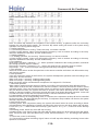
1.1 X Multi series line up ------------------------------------------------------------------------------------------3
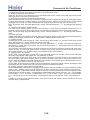
1.2 Operation temperature range ------------------------------------------------------------------------------ 3
1.3 Product features ----------------------------------------------------------------------------------------------- 4
2.Specifications ---------------------------------------------------------------------------------------------------- 6
3.Dimension ---------------------------------------------------------------------------------------------------------17
4.Pipe and wiring installation ----------------------------------------------------------------------------------- 21
4.1 Conbination of indoor and outdoor units ----------------------------------------------------------------21
4.2 Wiring connection ---------------------------------------------------------------------------------------------31
4.3 Limitation on the installation ------------------------------------------------------------------------------- 34
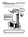
4.4 Outdoor unit installation -------------------------------------------------------------------------------------37
4.5 Cassette type installation ----------------------------------------------------------------------------------- 44
4.6 Convertible type installation --------------------------------------------------------------------------------51
4.7 Duct type installation -----------------------------------------------------------------------------------------64
4.8 Console type installation ------------------------------------------------------------------------------------74
4.9 Wall mounted type installation -----------------------------------------------------------------------------81
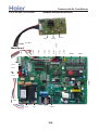
5.PCB photo,wiring diagram and function description ----------------------------------------------------85
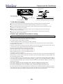
5.1 Outdoor unit -----------------------------------------------------------------------------------------------------85
5.1.1 Outdoor PCB photo ----------------------------------------------------------------------------------------85
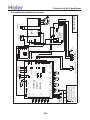
5.1.2 Outdoor wiring diagram -----------------------------------------------------------------------------------86
5.1.3 PCB function description --------------------------------------------------------------------------------- 90
5.2 Indoor unit ------------------------------------------------------------------------------------------------------- 90
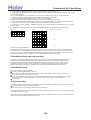
5.2.1 Cassette and duct type PCB photo --------------------------------------------------------------------90
5.2.2 Cassette and duct type wiring diagram ---------------------------------------------------------------98
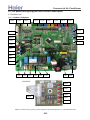
5.2.3 Convertible type PCB photo -----------------------------------------------------------------------------100
5.2.4 Convertible type wiring diagram ------------------------------------------------------------------------101
5.2.5 Converible type PCB function description ----------------------------------------------------------- 102
5.2.6 Console type PCB ----------------------------------------------------------------------------------------- 108
5.2.7 Console type wiring diagram ---------------------------------------------------------------------------- 109
5.2.8 Console type PCB function description ---------------------------------------------------------------110
5.2.9 Wall mounted type PCB photo --------------------------------------------------------------------------111
5.2.10 Wall mounted type wiring diagram ------------------------------------------------------------------- 112
5.2.11 Wall mounted type PCB function description ------------------------------------------------------114
6.Diagnostic code --------------------------------------------------------------------------------------------------117
6.1.1 Outdoor unit diagnostic code ----------------------------------------------------------------------------117
6.1.2 Cassette type and convertible type diagnostic code ---------------------------------------------- 118
6.1.3 Duct type diagnostic code --------------------------------------------------------------------------------119
6.1.4 Console type diagnostic code ---------------------------------------------------------------------------121
6.1.5 Wall mounted type diagnostic code ------------------------------------------------------------------- 122
6.2 Trouble shooting ---------------------------------------------------------------------------------------------- 123
7.Assistant software -----------------------------------------------------------------------------------------------126
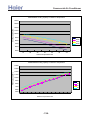
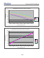
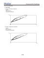
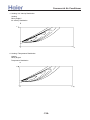
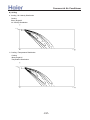
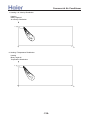
8.Performance curves -------------------------------------------------------------------------------------------- 127
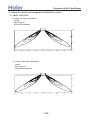
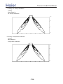
9. Indoor air velocity and temperature distribution---------------------------------------------------------- 133
9.1 AB092-182XCERA --------------------------------------------------------------------------------------------133
9.2 AC142-182XCERA --------------------------------------------------------------------------------------------135
9.3 AF092-122XCERA -------------------------------------------------------------------------------------------- 139
9.4 Wall mounted type -------------------------------------------------------------------------------------------- 141
10. Air flow and static pressure chart --------------------------------------------------------------------------142
-2-
.9773:1506 -5: .9825;5983:
,+ /383:06 5849:70;598
A?A rpqvtus i`hb`i cbe` kg
JK@IB[LNVJ
JKABB[LNVJ
JKADB[LNVJ
JKAHB[LNVJ
JXAHB[ONVJ
JXBBB[ONVJ
JLADB[LNVJ
JLAHB[LNVJ
JM@IB[SNVJ
JMABB[SNVJ
JMADB[SNVJ
JMAHB[SNVJ
JW@GB[YNVJ
JW@IB[YNVJ
JWABB[YNVJ
JWAHB[YNVJ
JO@IB[LNVJ
JOABB[LNVJ
JXBHB[QNVJ
JXCDB[QNVJ
JXCFB[QNVJ
JXBEB[PNVJ
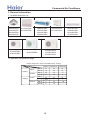
A?C Ug`h\jbfe j`dg`h\jkh` h\ea`
bel`hj`h ibeac` kebj= ikg`h cfm \d]b`ej j`dg? ^ffcbea
Lffcbea
Re_ffh
fkj_ffh
Q`\jbea
Re_ffh
fkj_ffh
V\j`_
T\nbdkd
MK L
BG
CB
AE
ZK L
MK L
AI
BC
AD
CE
DC
>E
ZK L
MK L
BD
BF
F
ZK L
B@
BG
A@
AD?E
>>
>>
MK L
ZK L
G
BC
>A@
F
AH
>>
-3-
Tbebdkd
Commercial Air Conditioner
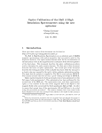
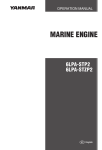
1 .3 Product features
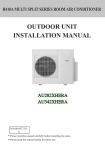
High efficienct, universal outdoor unit
The outdoor unit can match with cassette type ,duct type, convertible type, console type and wall mounted
type indoor unit. Outdoor unit can match with multiple indoor units. Even when you have already installed
the air conditioner, if you want to add or reduce one unit, go ahead freely as long as your operation
complies with our design. Greatly convenient for designer and installer.
Total indoor load can be up to 135% than the standard match
The total capacity of all indoor units can be 135% more than the nominal cooling capacity, but the total
indoor cooling capacity will not be increased.
Newly designed V- appearance indoor unit
The wall mounted type indoor unit adopts the newly designed V appearance, more fashion, more beautiful.
The unit is designed with the health airflow and sterilize function, which will make the air more healthy.
Also the air blow direction can be set as step or stepless control, much convenient to control.
Newly designed guarding plate of valve
In order to protect the valve against the dust, the rain or the snow, etc. we add a guarding plate to the
valve.
Adopt the much friendlier refrigerant R410a
The air conditioner system adopts the greatly friendly refrigerant R410a, which is protective for the ozone
layer and is good to avoid the earth getting warmer. Benefit for the environment.
Adopt the advanced DC inverter technology
The system adopts the advanced DC inverter technology, which can consume less power energy to realize
the equal efficiency, saving money for you.
With air inlet filter, enhance the air quality
The high efficiency filter can collect the dirt and remove the bacterium, which can be installed on the
easy-to-unload place, convenient to be cleaned.
Convenient infrared remote controller
This remote controller YR-H65 can realize the healthy air flow and sterilize function, it is mobile type
appearance, so smart and compact. And the infrared controller can be equipped with the controller holder,
convenient to fix the remote controller.
Auto restart function (optional)
All indoor units have auto-restart function. When the power supply cut off suddenly, the unit will
automatically recover the previous running mode once the power supply is on.
-4-
Commercial Air Conditioner
Self-diagnostic function
In the course of operation, if the failure occurs, the failure code will display on the wired controller
or on the operation panel. Then according to the failure code chart, you can eliminate the failure soon.
Central control function, if connected with a detector and a central controller
That is convenient for building management.
Adjustable heating temperature compensation
In heating mode, the temperature compensation can be adjusted by the remote controller. If you do not
want the compensation, you can set the compensation as 0 degree.
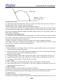
Software for diagnostic installation
After installation, you can use file "X-MULTI Setup Assistant " to know the installation is OK or
not, if system has error, software will give you trouble shooting.
-5-
>_]]VbTZR\ <Zb >_^UZdZ_^Vb
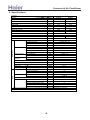
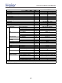
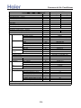
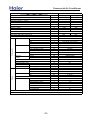
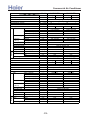
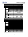
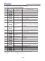
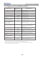
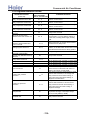
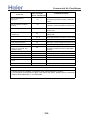
2. Specifications
Item
Model
Piping
Outdoor unit
Function
Rating capacity
Power input (indoor + outdoor)
Current input (indoor + outdoor)
EER / COP
Minimum capacity
Power input
Maximum capacity
Power input (indoor + outdoor)
Power source
Max.Running current (indoor + outdoor)
Power facor(under rating power input)
Fuse size (recommended size)
Compressor
Model / Manufacture
Oil charge and type
Type
Number
Fan
Type × Number
Speed
Motor output/input power
Air-flows (H/M/L)
Heat exchanger
Type / Diameter
Face area
Dimension
External
(WxDxH)
Package
Refrigerant control method
Defrosting method
Crankcase heater power
Noise level
H/M/L
Weight
Net / Shipping
Refrigerant
Type / Charge
No need to recharge
Recharge
Pipe
Liquid
Gas
Connecting method
Between I.U &O.U Max.Drop between IU & OU
Max.Drop between IU & OU
Max.Drop between indoor units
Max.Piping length between IU & OU
Max.Total liquid piping length
——
W
W
A
W/W
W
W
W
W
——
A/A
——
A
——
——
——
——
——
r/min
W
m³/h
mm
m²
mm
mm
——
——
W
dB(A)
kg / kg
kg
m
g/m
mm
mm
——
m
m
m
m
m
AU182XFERA
Cooling
5300
1650
7.3
3.21
1500
500
5800
2300
Heating
7000
1800
8.0
3.89
1800
500
7300
2300
1PH, 220-230V~, 50Hz
10.2
99%
10.2
99%
25
TNB175FLBM / MELCO
870CC, MEL 56
Twin Rotary (DC inverter)
1
Axial × 1
850 / 700 / 500
35/85
about 3000
TP2M / 7.0
about 0.52
928/288/680
1015/405/760
PMVs
Automatic by reversible cycle
35
51/-/54 / 60
R410A / 2.0
30
20
3* Φ6.35
3* Φ9.52
Flared
10(indoor unit lower than outdoor unit)
15 (indoor unit higher than outdoor unit)
5
25
45
1. The above performance data are from the combination of AU182XFERA+2*AS092XVERA+AS122XVERA.
2. Large drop and long piping installation will obviously reduce the totao capacity.
-6-
>_]]VbTZR\ <Zb >_^UZdZ_^Vb
Item
Model
Piping
Outdoor unit
Function
Rating capacity
Power input (indoor + outdoor)
Current input (indoor + outdoor)
EER / COP
Minimum capacity
Power input
Maximum capacity
Power input (indoor + outdoor)
Power source
Max.Running current (indoor + outdoor)
Power facor(under rating power input)
Fuse size (recommended size)
Compressor
Model / Manufacture
Oil charge and type
Type
Number
Fan
Type × Number
Speed
Motor output/input power
Air-flows (H/M/L)
Heat exchanger
Type / Diameter
Face area
Dimension
External
(WxDxH)
Package
Refrigerant control method
Defrosting method
Crankcase heater power
Noise level
H/M/L
Weight
Net / Shipping
Refrigerant
Type / Charge
No need to recharge
Recharge
Pipe
Liquid
Gas
Connecting method
Between I.D &O.D
Max.Drop between IU & OU
Max.Drop between IU & OU
Max.Drop between indoor units
Max.Piping length between IU & OU
Max.Total liquid piping length
——
W
W
A
W/W
W
W
W
W
——
A/A
——
A
——
——
——
——
——
r/min
W
m³/h
mm
m²
mm
mm
——
——
W
dB(A)
kg / kg
kg
m
g/m
mm
mm
——
m
m
m
m
m
AU222XFERA
Cooling
6400
2100
9.3
3.04
1500
500
6800
2900
Heating
7300
2000
8.9
3.65
1800
500
7500
2900
1PH, 220-230V~, 50Hz
12.9
99%
12.9
99%
25
TNB175FLBM / MELCO
870CC, MEL 56
Twin Rotary (DC inverter)
1
Axial × 1
960 / 700 / 500
35/100
about 3200
TP2M / 7.0
about 0.52
928/288/680
1015/405/760
PMVs
Automatic by reversible cycle
35
55/-/54 / 60
R410A / 2.0
30
20
3* Φ6.35
3* Φ9.52
Flared
10(indoor unit lower than outdoor unit)
15 (indoor unit higher than outdoor unit)
5
25
45
1. The above performance data are from the combination of AU222XFERA+AS092XVERA+2*AS122XVERA.
2. Large drop and long piping installation will obviously reduce the totao capacity.
-7-
>_]]VbTZR\ <Zb >_^UZdZ_^Vb
Item
Model
Piping
Outdoor unit
Function
Rating capacity
Power input (indoor + outdoor)
Current input (indoor + outdoor)
EER / COP
Minimum capacity
Power input
Maximum capacity
Power input (indoor + outdoor)
Power source
Max.Running current (indoor + outdoor)
Power facor(under rating power input)
Fuse size (recommended size)
Compressor
Model / Manufacture
Oil charge and type
Type
Number
Fan
Type × Number
Speed
Motor output/input power
Air-flows (H/M/L)
Heat exchanger
Type / Diameter
Face area
Dimension
External
(WxDxH)
Package
Refrigerant control method
Defrosting method
Crankcase heater power
Noise level
H/M/L
Weight
Net / Shipping
Refrigerant
Type / Charge
No need to recharge
Recharge
Pipe
Liquid
Gas
Connecting method
Between I.D &O.D
Max.Drop between IU &OU
Max.Drop between IU & IU
Max.Drop between IU & OU
Max.Piping length between IU & OU
Max.Total length
——
W
W
A
W/W
W
W
W
W
——
A/A
——
A
——
——
——
——
——
r/min
W
m³/h
mm
m²
mm
mm
——
——
W
dB(A)
kg / kg
kg
m
g/m
mm
mm
——
m
m
m
m
m
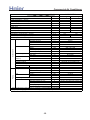
AU252XGERA
-8-
Heating
8000
2200
10.4
3.64
1500
500
8200
3200
1800
500
9000
3000
1PH, 220-230V~, 50Hz
14.3
99%
13.5
99%
30
TNB175FLBM / MELCO
870CC
DC TWIN ROTARY
1
Axial × 1
930 / 700 / 500
98/200
about 3400
TP2M / 7.0
about 0.67
976/335/732
1065/420/815
PMVs
Automatic by reversible cycle
35
57/-/58 / 64
R410A / 2.5
30
20
4* Φ6.35
4* Φ9.52
Flared
10(indoor unit lower than outdoor unit)
15 (indoor unit higher than outdoor unit)
5
25
60
1. The above performance data are from the combination of AU252XGERA+3*AD092XLERA
2. Large drop and long piping installation will obviously reduce the total capacity.
Cooling
7250
2250
10.4
3.22
>_]]VbTZR\ <Zb >_^UZdZ_^Vb
Model
Function
Rating capacity
Power input (indoor + outdoor)
Current input (indoor + outdoor)
EER / COP
Minimum capacity
Power input
Maximum capacity
Power input (indoor + outdoor)
Power source
Max.Running current (indoor + outdoor)
Power facor(under rating power input)
Fuse size (recommended size)
Compressor
Model / Manufacture
Oil charge and type
Type
Number
Fan
Type × Number
Speed
Motor output/input power
Air-flows (H/M/L)
Heat exchanger
Type / Diameter
Face area
Dimension
External
(WxDxH)
Package
Refrigerant control method
Defrosting method
Crankcase heater power
Noise level
H/M/L
Weight
Net / Shipping
Refrigerant
Type / Charge
No need to recharge
Recharge
Pipe
Liquid
Gas
Connecting method
Between I.D &O.D Max.Drop between IU &OU
Max.Drop between IU & IU
Max.Drop between IU & OU
Max.Piping length between IU & OU
Max.Total length
——
W
W
A
W/W
W
W
W
W
——
A/A
——
A
——
——
——
——
——
r/min
W
m³/h
mm
m²
mm
mm
——
——
W
dB(A)
kg / kg
kg
m
g/m
mm
mm
——
m
m
Piping
Outdoor unit
Item
m
m
m
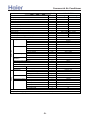
AU282XHERA
Cooling
8000
2480
11.0
3.22
Heating
10000
2700
11.9
3.70
1500
550
9500
3800
1800
550
11000
3800
1PH, 220-230V~, 50Hz
16.8
99%
16.8
99%
30
TNB220FLBM / MELCO
870CC
Twin Rotary (DC inverter)
1
Axial × 1
850 / 700 / 500
60/150
about 4000
TP2M / 7.0
about 0.75
1068x340x830
1100x440x979
PMVs
Automatic by reversible cycle
35
58/-/74 / 89
R410A / 2.6
40
20
4* Φ6.35
4* Φ9.52
Flared
10(indoor unit lower than outdoor unit)
15 (indoor unit higher than outdoor unit)
5
25
60
1. The above performance data are from the combination of AU282XHERA+2*AS092XVERA+2*AS122XVERA.
2. Large drop and long piping installation will obviously reduce the total capacity.
-9-
>_]]VbTZR\ <Zb >_^UZdZ_^Vb
Item
Model
Piping
Outdoor unit
Function
Rating capacity
Power input (indoor + outdoor)
Current input (indoor + outdoor)
EER / COP
Minimum capacity
Power input
Maximum capacity
Power input (indoor + outdoor)
Power source
Max.Running current (indoor + outdoor)
Power facor(under rating power input)
Fuse size (recommended size)
Compressor
Model / Manufacture
Oil charge and type
Type
Number
Fan
Type × Number
Speed
Motor output/input power
Air-flows (H/M/L)
Heat exchanger
Type / Diameter
Face area
Dimension
External
(WxDxH)
Package
Refrigerant control method
Defrosting method
Crankcase heater power
Noise level
H/M/L
Weight
Net / Shipping
Refrigerant
Type / Charge
No need to recharge
Recharge
Pipe
Liquid
Gas
Connecting method
Between I.D &O.D Drop between IU & OU
Piping length between IU & OU
Total liquid piping length
Max.Drop between IU &OU
Max.Drop between IU & IU
Max.Piping length between IU & OU
Max.Total length
——
W
W
A
W/W
W
W
W
W
——
A/A
——
A
——
——
——
——
——
r/min
W
m³/h
mm
m²
mm
mm
——
——
W
dB(A)
kg / kg
kg
m
g/m
mm
mm
——
m
m
m
m
m
m
m
AU342XHERA
Cooling
10000
3200
14.3
3.13
Heating
11000
3200
14.3
3.44
1500
550
11000
4000
1800
550
11500
4000
1PH, 220-230V~, 50Hz
18.1
99%
18.1
99%
30
TNB220FLBM / MELCO
870CC
Twin Rotary (DC inverter)
1
Axial × 1
990/ 840/ 590
130/300
about 4300
TP2M / 7.0
about 0.75
1068x340x830
1100x440x979
PMVs
Automatic by reversible cycle
35
59/-/74 / 89
R410A / 3.0
40
20
4* Φ6.35
4* Φ9.52
Flared
≤5
≤10
≤40
10(indoor unit lower than outdoor unit)
15 (indoor unit higher than outdoor unit)
25
60
1. The above performance data are from the combination of AU342XHERA+2*AD092XLERA+2*AD122XLERA.
2. Large drop and long piping installation will obviously reduce the total capacity.
-10-
>_]]VbTZR\ <Zb >_^UZdZ_^Vb
Item
Model
Piping
Outdoor unit
Function
Rating capacity
Power input (indoor + outdoor)
Current input (indoor + outdoor)
EER / COP
Minimum capacity
Power input
Maximum capacity
Power input (indoor + outdoor)
Power source
Max.Running current (indoor + outdoor)
Power facor(under rating power input)
Fuse size (recommended size)
Compressor
Model / Manufacture
Oil charge and type
Type
Number
Fan
Type × Number
Speed
Motor output/input power
Air-flows (H/M/L)
Heat exchanger
Type / Diameter
Face area
Dimension
External
(WxDxH)
Package
Refrigerant control method
Defrosting method
Crankcase heater power
Noise level
H/M/L
Weight
Net / Shipping
Refrigerant
Type / Charge
No need to recharge
Recharge
Pipe
Liquid
Gas
Connecting method
Between I.D &O.D
Drop between IU & OU
Piping length between IU & OU
Total liquid piping length
Max.Drop between IU &OU
Max.Drop between IU & IU
Max.Piping length between IU & OU
Max.Total length
——
W
W
A
W/W
W
W
W
W
——
A/A
——
A
——
——
——
——
——
r/min
W
m³/h
mm
m²
mm
mm
——
——
W
dB(A)
kg / kg
kg
m
g/m
mm
mm
——
m
m
m
m
m
m
m
AU362XHERA
Cooling
10000
3200
14.3
3.13
Heating
11000
3200
14.3
3.44
1500
550
11000
4000
1800
550
11500
4000
1PH, 220-230V~, 50Hz
18.1
99%
18.1
99%
30
TNB220FLBM / MELCO
870CC
Twin Rotary (DC inverter)
1
Axial × 1
990/ 840/ 590
130/300
about 4300
TP2M / 7.0
about 0.75
1068x340x830
1100x440x979
PMVs
Automatic by reversible cycle
35
59/-/74 / 89
R410A / 3.0
40
20
5* Φ6.35
5* Φ9.52
Flared
≤5
≤10
≤40
10(indoor unit lower than outdoor unit)
15 (indoor unit higher than outdoor unit)
25
60
1. The above performance data are from the combination of AU362XHERA+2*AD092XLERA+2*AD122XLERA.
2. Large drop and long piping installation will obviously reduce the total capacity.
-11-
>_]]VbTZR\ <Zb >_^UZdZ_^Vb
Item
Model
Piping
Function
——
Capacity
W
Power cable
——
Communication cable
——
Dehumidifying capacity
10‐³×m³/h
Power source
N, V, Hz
Running current
A/A
Fan
Type × Number
——
Speed
r/min
Motor output/input power
W
Air-flows (H/M/L)
m³/h
Heat exchanger Type / Diameter
mm
Face area
m²
Dimension
External
mm
(L×W×H)
Package
mm
Drainage pipe
material, diameter
mm
Controller type
——
Refrigerant control
——
Noise level
H/M/L
dB(A)
Weight
Net / Shipping
kg / kg
Refrigerant
Type
——
Pipe
Liquid
mm
Gas
mm
Connecting method
——
Item
AS072XVERA
Cooling
2000
Heating
2300
Piping
-12-
Heating
2900
3 × (1.0~1.5mm2 )
2x(0.75~1.25mm2 ), must be shieled
1.0
/
1.0
/
1,220-230~, 50
0.15
0.15
0.15
0.15
CROSS×1
CROSS×1
1150/1050/950
1200/1100/1000
16/40
16/40
480/430/380
520/450/390
TP2M / 7×0.35
about 0.15
about 0.15
795*197*265
795×197×265
880×315×330
880×315×330
PVC, 11.4/16.4
Infrared (YR-H65)
PMV on outdoor unit
36/33/30
38/34/31
7.6/10.6
7.6/10.6
R410A
R410A
6.35
6.35
9.52
9.52
Flared
Flared
AS122XVERA
Function
——
Capacity
W
Dehumidifying capacity
10‐³×m³/h
Power cable
——
Communication cable
——
Power source
N, V, Hz
Running current
A/A
Fan
Type × Number
——
Speed
r/min
Motor output/input power
W
Air-flows (H-M-L)
m³/h
Heat exchanger Type / Diameter
mm
Face area
m²
Dimension
External
mm
(L×W×H)
Package
mm
Drainage pipe
material, diameter
mm
Controller type
——
Refrigerant control
——
Noise level
H/M/L
dB(A)
Weight
Net / Shipping
kg / kg
Refrigerant
Type
——
Pipe
Liquid
mm
Gas
mm
Connecting method
——
AS092XVERA
Cooling
2500
Cooling
3200
1.6
Heating
3800
/
AS182XVERA
Cooling
5000
2.0
Heating
5500
/
3 × (1.0~1.5mm2 )
2x(0.75~1.25mm2 ), must be shieled
1, 220~230, 50
0.15
0.15
0.25
0.25
CROSS×1
CROSS×1
1250/1150/1050
1200/1050/950
16/40
25/40
550/480/430
600/550/500
TP2M / 7×0.35
about 0.20
about 0.20
795×197×265
870*225*305
880×315×330
962*365*312
PVC, 11.4/16.4
Infrared (YR-H65)
PMV on outdoor unit
39/36/33
42/40/37
7.6/10.6
12/15
R410A
R410A
6.35
6.35
9.52
12.7
Flared
Flared
>_]]VbTZR\ <Zb >_^UZdZ_^Vb
Item
Model
Function
Capacity
Dehumidifying capacity
Power cable
Communication cable
Power source
Running current
Fan
Heat exchanger
Panel
Piping
Dimension
(L×W×H)
Type × Number
Speed
Motor output/input power
Air-flows (H/M/L)
Type / Diameter
Face area
Temp. scope
External
Package
material, diameter
Drainage pipe
Controller type
Refrigerant control
Fresh air hole dimension
Electricity Heater
Noise level
H/M/L
Weight
Net / Shipping
Refrigerant
Type
Pipe
Liquid
Gas
Connecting method
Dimension
External
(L×W×H)
Package
Weight
Net / Shipping
Item
Model
Function
Capacity
Dehumidifying capacity
Power cable
Communication cable
Power source
Running current
Fan
Heat exchanger
Dimension
(L×W×H)
Type × Number
Speed
Motor output/input power
Air-flows (H/M/L)
Type / Diameter
Face area
Temp. scope
External
Package
material, diameter
Piping
Drainage pipe
Controller type
Refrigerant control
Fresh air hole dimension
Electricity Heater
Noise level
H/M/L
Weight
Net / Shipping
Refrigerant
Type
Pipe
Liquid
Gas
Connecting method
Dimension
External
Package
Weight
Net / Shipping
* o.d.=outer diameter; i.d.=inner diameter
Panel
AB092XCERA
——
W
10‐³×m³/h
——
——
N, V, Hz
A
——
r/min
W
m³/h
mm
m²
℃
mm
mm
mm
——
——
mm
——
dB(A)
kg / kg
——
mm
mm
——
mm
mm
kg / kg
——
W
10‐³×m³/h
——
——
N, V, Hz
A
——
r/min
W
m³/h
mm
m²
℃
mm
mm
mm
——
——
mm
——
dB(A)
kg / kg
——
mm
mm
——
mm
mm
kg / kg
-13-
AB122XCERA
Cooling
2500
1.0
Heating
Cooling
Heating
2900
3500
3800
/
1.2
/
3 × (1.0~1.5mm 2 )
2x(0.75~1.25mm 2 ), must be shieled
1, 220~230, 50
0.45
0.45
0.45
0.45
CENTRIFUGAL × 1
CENTRIFUGAL × 1
650/570/520
750/650/540
38/95
38/95
670/600/550
620/560/530
7
7
about 0.273
about 0.273
cooling: 6~7 / heating: 43~60
570/570/260
570/570/260
718/680/380
718/680/380
PVC, 32/26(o.d./I.d.*)
PVC, 32/26(o.d./I.d.*)
Infrared YR-H71 or wired YR-E12
PMV on outdoor unit
100
100
/
/
41/39/38
44/40/37
17/20
17/20
R410A
R410A
6.35
6.35
9.52
9.52
Flared
Flared
700/700/60
700/700/60
740/750/115
740/750/115
2.8/4.8
2.8/4.8
AB142XCERA
Cooling
4100
1.6
AB182XCERA
Heating
Cooling
Heating
4600
5000
5500
/
2
/
3 × 0.75mm 2
2x(0.75~1.25mm 2 ), must be shieled
1, 220~230, 50
0.45
0.45
0.45
0.45
CENTRIFUGAL × 1
CENTRIFUGAL × 1
750/650/540
750/650/540
38/95
38/95
670/600/550
670/600/550
7
7
about 0.273
about 0.273
cooling: 6~7 / heating: 43~60
570/570/260
570/570/260
718/680/380
718/680/380
PVC, 32/26(o.d./I.d.*)
PVC, 32/26(o.d./I.d.*)
Infrared YR-H71 or wired YR-E12
PMV on outdoor unit
100
100
/
/
44/40/37
44/40/37
19/23.5
19/23.5
R410A
R410A
6.35
6.35
12.7
12.7
Flared
Flared
700/700/60
700/700/60
740/750/115
740/750/115
2.8/4.8
2.8/4.8
>_]]VbTZR\ <Zb >_^UZdZ_^Vb
Item
Model
Function
Capacity
Dehumidifying capacity
Power cable
Communication cable
Power source
Running current
Fan
Heat exchanger
Piping
Dimension
(L×W×H)
Type × Number
Speed
Motor output/input power
Air-flows (H/M/L)
Type / Diameter
Face area
Temp. scope
External
Package
material, diameter
Drainage pipe
Controller type
Refrigerant control
Fresh air hole dimension
Electricity Heater
Noise level
H/M/L
Weight
Net / Shipping
Refrigerant
Type
Pipe
Liquid
Gas
Connecting method
Item
Model
Function
Capacity
Dehumidifying capacity
Power cable
Communication cable
Power source
Running current
Fan
Heat exchanger
Dimension
(L×W×H)
Type × Number
Speed
Motor output/input power
Air-flows (H/M/L)
Type / Diameter
Face area
Temp. scope
External
Package
material, diameter
Drainage pipe
Controller type
Refrigerant control
Fresh air hole dimension
Electricity Heater
Noise level
H/M/L
Weight
Net / Shipping
Refrigerant
Type
Pipe
Liquid
Gas
Connecting method
* o.d.=outer diameter; i.d.=inner diameter
Piping
——
W
10‐³×m³/h
——
——
N, V, Hz
A
——
r/min
W
m³/h
mm
m²
℃
mm
mm
mm
——
——
mm
——
dB(A)
kg / kg
——
mm
mm
——
——
W
10‐³×m³/h
——
——
N, V, Hz
A
——
r/min
W
m³/h
mm
m²
℃
mm
mm
mm
——
——
mm
——
dB(A)
kg / kg
——
mm
mm
——
-14-
AD092XLERA
Cooling
2500
1.0
Heating
2900
/
AD122XLERA
Cooling
3500
1.2
Heating
3800
/
3 × (1.0~1.5mm 2 )
2x(0.75~1.25mm2 ), must be shieled
1, 220~230, 50
0.35
0.35
0.35
0.35
CROSS × 1
CROSS × 1
1050/950/850/750
1050/950/850/750
30/75
30/75
550/500/450/400
550/500/450/400
7
7
about 0.12
about 0.12
cooling: 6~7 / heating: 43~60
610×500×220
610×500×220
695/536/265
695/536/265
(o.d./I.d.*)
(o.d./I.d.*)
Wired controller YR-E12
PMV on outdoor unit
/
/
/
/
43/40/38/35
43/40/38/35
14/16
14/16
R410A
R410A
6.35
6.35
9.52
9.52
Flared
Flared
AD142XLERA
Cooling
4100
1.6
AD182XLERA
Heating
Cooling
4600
5000
/
2.0
3 × 0.75mm2
Heating
5500
/
2x(0.75~1.25mm2 ), must be shieled
1, 220~230, 50
0.85
0.85
0.85
0.85
CROSS × 2
CROSS × 2
1270/1160/1020/900
1270/1160/1020/900
80/200
80/200
780/700/650/600
780/700/650/600
7
7
about 0.23
about 0.23
cooling: 6~7 / heating: 43~60
1090×500×220
1090×500×220
1161/536/269
1161/536/269
(o.d./I.d.*)
(o.d./I.d.*)
Wired YR-E12
PMV on outdoor unit
/
/
/
/
46/44/40/38
46/44/40/38
25/29
25/29
R410A
R410A
6.35
6.35
12.7
12.7
Flared
Flared
>_]]VbTZR\ <Zb >_^UZdZ_^Vb
Item
Model
Function
Capacity
Dehumidifying capacity
Power cable
Communication cable
Power source
Running current
Fan
Heat exchanger
Dimension
(L×W×H)
Type × Number
Speed
Motor output/input power
Air-flows (H/M/L)
Type / Diameter
Face area
Temp. scope
External
Package
material, diameter
Piping
Drainage pipe
Controller type
Refrigerant control
Fresh air hole dimension
Electricity Heater
Noise level
H/M/L
Weight
Net / Shipping
Refrigerant
Type
Pipe
Liquid
Gas
Connecting method
* o.d.=outer diameter; i.d.=inner diameter
——
W
10‐³×m³/h
——
——
N, V, Hz
A
——
r/min
W
m³/h
mm
m²
℃
mm
mm
mm
——
——
mm
——
dB(A)
kg / kg
——
mm
mm
——
-15-
AC142XCERA
Cooling
4100
1.6
AC182XCERA
Heating
Cooling
4600
5000
/
2
3 × 0.75mm 2
Heating
5500
/
2x(0.75~1.25mm 2 ), must be shieled
1, 220~230, 50
shieled
0.45
0.45
0.45
0.45
CENTRIFUGAL × 2
CENTRIFUGAL × 2
1150/1050/850
1150/1050/850
28/80
28/80
700/640/580
700/640/580
TP2M / 7×0.35
about 0.49
about 0.49
cooling: 6~7 / heating: 43~60
990/655/199
990/655/199
1150/750/300
1150/750/300
PVC, 20/18(o.d./I.d.*)
PVC, 20/18(o.d./I.d.*)
Infrared YR-H71 or wired YR-E12
PMV on outdoor unit
/
/
16.4/11.4(o.d./I.d. 16.4/11.4(o.d./I.d.
/
/
48/45/41
48/45/41
28.3/34.3
28.3/34.3
R410A
R410A
6.35
6.35
12.7
12.7
Flared
Flared
>_]]VbTZR\ <Zb >_^UZdZ_^Vb
Item
Model
AF092XCERA
AF122XCERA
Cooling
Heating
Cooling
Heating
——
2500
2900
3500
3800
W
1.0
/
1.2
/
10‐³×m³/h
3 × (1.0~1.5mm 2 )
——
2x(0.75~1.25mm 2 ), must be shieled
——
1, 220~230, 50
N, V, Hz
A
0.45
0.45
0.45
0.45
CROSS × 2
CROSS × 2
Type × Number
——
1000/900/800
1050/950/850
Speed
r/min
50/100
50/100
Motor output/input power
W
480/420/370
510/450/400
Air-flows (H/M/L)
m³/h
Heat exchanger
TP2M / 7×0.35
Type / Diameter
mm
about 0.25
about 0.25
Face area
m²
cooling: 6~7 / heating: 43~60
Temp. scope
℃
Dimension
720/205/630
720/205/630
External
mm
(WxDxH)
780/280/690
780/280/690
Package
mm
PVC, 16.4/11.4(o.d./I.d.*) PVC, 16.4/11.4(o.d./I.d.*)
Drainage pipe
material, diameter
mm
Infrared YR-H71
Controller type
——
PMV on outdoor unit
Refrigerant control
——
/
/
Fresh air hole dimension
mm
/
/
Electricity Heater
——
40/38/36
41/39/37
Noise level
H/M/L
dB(A)
17/20.7
17/20.7
Weight
Net / Shipping
kg / kg
R410A
R410A
Refrigerant
Type
——
Pipe
6.35
6.35
Liquid
mm
9.52
9.52
Gas
mm
Flared
Flared
Connecting method
——
* o.d.=outer diameter; i.d.=inner diameter
Piping
Function
Capacity
Dehumidifying capacity
Power cable
Communication cable
Power source
Running current
Fan
-16-
>_]]VbTZR\ <Zb >_^UZdZ_^Vb
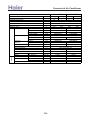
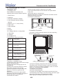
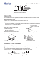
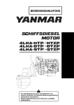
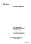
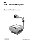
3. Dimension
AU182XFERA,AU222XFERA
928
810
18
50
288
319.5
680
113.5
583
113.5
48,.,965743
20/
1/*
,.
-..
0-*
/-*
-*1
++.
AU282XHERA:
1068
950
18
70
340
380
185
580
185
-17-
830
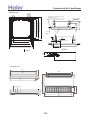
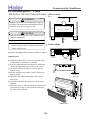
>_]]VbTZR\ <Zb >_^UZdZ_^Vb
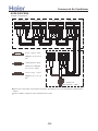
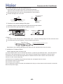
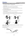
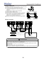
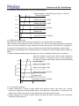
EJZZN[[N \UR[C
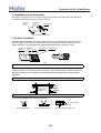
:;9
A9
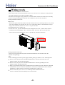
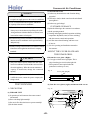
V]NYSJWNM MRZ[JULN KN[^NNU [QN LNRSRUP
JUM [QN WJUNSC ;>TT
:>9TT
@99TT 7WJUNS MRTNUZRVU8
WJUNS
LNRSRUP
B>
:A9
><>TT 7KN[^NNU Z\ZWNUZRVU WVSNZ8
OYNZQ JRY QVSN
>@9TT 7RUMVVY \UR[ MRTNUZRVU8
?>9TT 7LNRSRUP VWNURUP MRTNUZRVU8
:=9
@99TT 7WJUNS MRTNUZRVU8
HGFI D
HGFI D
:=> :99 A9
5;:?7<=8697 >:8=4
1-+
1+0
1++
22+
,++
100
/+
.0
.0
.+
-++
33+
-18-
-/+
,33
3++
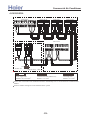
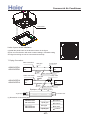
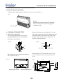
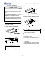
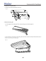
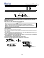
<;9TT
Z\ZWNUZRVU QVSMNY
@>
>@9TT 7RUMVVY \UR[ MRTNUZRVU8
>@
SRX\RM WRWN
?>
?>9TT 7LNRSRUP VWNURUP MRTNUZRVU8
MYJRUJPN WRWN
PJZ WRWN
?9TT
B9
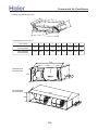
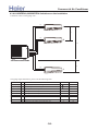
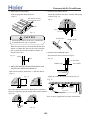
>_]]VbTZR\ <Zb >_^UZdZ_^Vb
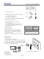
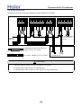
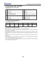
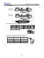
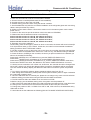
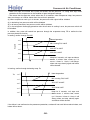
:FJKJMH DNMDFBKFE QSOF RMJQ8
U
Y
T
X
[
Z
W
\
V
=MPQBKKBQJNM EJLFMPJNM8+LL,
@MJQ LNEFK
B
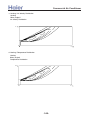
9;.70A><?9
9;/00A><?9
316
9;/20A><?9
9;/60A><?9
/..0
D
E
F
G
H
I
J
261-3
/1/
4/.
033
/.3
2/6
3.6
00.
261-3
/1/
//.3
033
/.3
66.
75.
00.
C
256
9;.70A><?9
9;/00A><?9
00.
9;/20A><?9
9;/60A><?9
72.
00.
-19-
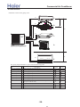
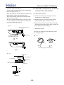
>_]]VbTZR\ <Zb >_^UZdZ_^Vb
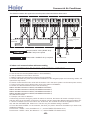
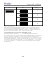
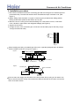
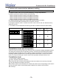
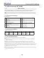
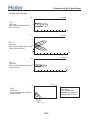
Console type unit:
.,*
/+*
+*-
Wall Mounted Type
A
B
C
model
A
B
C
AS07/09/122XVERA
197
265
795
AS182XVERA
225
305
870
-20-
>_]]VbTZR\ <Zb >_^UZdZ_^Vb
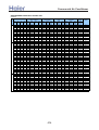
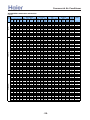
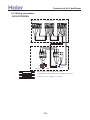
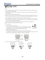
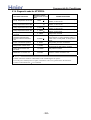
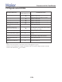
4. Pipe and wiring installation
4.1 Multi combination and the data
AU182XFERA combination and the data
COOLING
TRI (1x3)
BI (1x2)
Combinations
Co
mb. Unit Unit Unit
A
B
C
7
7
—
7
9
—
7
12
—
7
14
—
7
18
—
9
9
—
9
12
—
9
14
—
9
18
—
12
12
—
12
14
—
12
18
—
7
7
7
7
7
9
7
7
12
7
9
9
7
9
12
9
9
9
9
9
12
capacity(kW)
(Nom. cooling)
Unit Unit Unit
A
B
C
2.0
2.0
—
2.0
2.5
—
2.0
3.2
—
1.73 3.47
—
1.48 3.72
—
2.5
2.5
—
2.3
2.9
—
2.0
3.2
—
1.73 3.47
—
2.6
2.6
—
2.42 2.78
—
2.18 3.12
—
1.73 1.73 1.73
1.60 1.60 2.00
1.39 1.39 2.42
1.48 1.86 1.86
1.30 1.63 2.27
1.73 1.73 1.73
1.56 1.56 2.18
total cooling
capacity(kW)
min. rated max.
data data data
total power input
(kW)
min. rated max.
data data Data
total current
(A)@230V
min. rated max.
data data
Data
1.00
1.00
1.00
1.00
1.00
1.00
1.00
1.00
1.00
1.00
1.00
1.00
1.50
1.50
1.50
1.50
1.50
1.50
1.50
0.47
0.47
0.47
0.55
0.55
0.47
0.47
0.55
0.55
0.47
0.55
0.55
0.50
0.50
0.50
0.50
0.50
0.50
0.50
2.15
2.15
2.15
2.50
2.50
2.15
2.15
2.50
2.50
2.15
2.50
2.50
2.29
2.29
2.29
2.29
2.29
2.29
2.29
4.00
4.50
5.20
5.20
5.20
5.00
5.20
5.20
5.20
5.20
5.20
5.30
5.20
5.20
5.20
5.20
5.20
5.20
5.30
4.40
4.90
5.80
5.80
5.80
5.40
5.80
5.80
5.80
5.80
5.80
5.80
5.80
5.80
5.80
5.80
5.80
5.80
5.80
1.60
1.75
1.75
1.85
1.85
1.75
1.75
1.85
1.85
1.75
1.85
1.85
1.70
1.70
1.70
1.70
1.65
1.65
1.65
2.30
2.30
2.30
2.30
2.30
2.30
2.30
2.30
2.30
2.30
2.30
2.30
2.30
2.30
2.30
2.30
2.30
2.30
2.30
7.80
7.80
7.80
8.30
8.30
7.80
7.80
8.30
8.30
7.80
8.30
8.30
7.62
7.62
7.62
7.62
7.62
7.62
7.40
10.20
10.20
G
10.20
G
10.20
G
10.20
10.20
10.20
10.20
10.20
10.20
10.20
10.20
10.20
10.20
10.20
10.20
10.20
10.20
10.20
ENERGY
EER
LABEL
(W/W)
rated
capacity
2.50
E
2.57
E
2.97
C
2.81
C
2.81
C
2.86
C
2.97
C
2.81
C
2.81
C
2.97
C
2.81
C
2.86
C
3.06
B
3.06
B
3.06
B
3.06
B
3.15
B
3.15
B
3.21
A
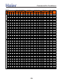
HEATING
TRI (1x3)
BI (1x2)
Combinations
Co
mb. Unit Unit Unit
A
B
C
7
7
—
7
9
—
7
12
—
7
14
—
7
18
—
9
9
—
9
12
—
9
14
—
9
18
—
12
12
—
—
12
14
—
12
18
7
7
7
7
7
9
7
7
12
7
9
9
7
9
12
9
9
9
9
9
12
capacity(kW)
(Nom. heating)
Unit Unit Unit
A
B
C
2.30 2.30
—
2.30 2.90
—
2.30 3.80
—
2.30 4.60
—
2.10 4.90
—
2.90 2.90
—
2.80 3.80
—
2.70 4.30
—
2.40 4.60
—
3.50 3.50
—
3.20 3.80
—
2.85 4.15
—
2.30 2.30 2.30
2.15 2.15 2.70
1.95 1.95 3.10
2.00 2.50 2.50
1.80 2.25 2.95
2.30 2.30 2.30
2.10 2.10 2.80
total heating
capacity(kW)
min. rated max.
data data data
total power input
(kW)
min. rated max.
data data Data
total current
(A)@230V
min. rated max.
data data
Data
1.20
1.20
1.20
1.30
1.30
1.20
1.20
1.30
1.30
1.20
1.30
1.30
1.50
1.50
1.50
1.50
1.50
1.50
1.50
0.55
0.55
0.55
0.60
0.60
0.55
0.55
0.60
0.60
0.55
0.60
0.60
0.55
0.55
0.55
0.55
0.55
0.55
0.55
2.50
2.50
2.50
2.65
2.65
2.50
2.50
2.65
2.65
2.50
2.65
2.65
2.50
2.50
2.50
2.50
2.50
2.50
2.50
4.60
5.20
6.10
6.90
7.00
5.80
6.60
7.00
7.00
7.00
7.00
7.00
6.90
7.00
7.00
7.00
7.00
6.90
7.00
5.00
5.70
6.50
7.30
7.30
6.50
6.80
7.30
7.30
7.30
7.30
7.30
6.90
7.30
7.30
7.30
7.30
7.30
7.30
-21-
1.85
2.05
1.90
1.95
1.95
1.90
1.90
2.00
2.00
1.95
2.00
2.00
2.05
2.00
1.95
1.95
1.90
1.85
1.80
2.30
2.30
2.30
2.30
2.30
2.30
2.30
2.30
2.30
2.30
2.30
2.30
2.30
2.30
2.30
2.30
2.30
2.30
2.30
9.10
9.10
8.43
8.65
8.65
8.43
8.43
8.65
8.65
8.43
8.65
8.65
8.21
8.21
8.21
8.21
8.21
8.21
7.99
10.20
10.20
10.20
10.20
10.20
10.20
10.20
10.20
10.20
10.20
10.20
10.20
10.20
10.20
10.20
10.20
10.20
10.20
10.20
ENERGY
COP
LABEL
(W/W)
rated
capacity
2.49
F
2.54
F
3.21
C
3.54
B
3.59
B
3.05
C
3.47
B
3.50
B
3.50
B
3.59
B
3.50
B
3.50
B
3.37
C
3.50
B
3.59
B
3.59
B
3.68
A
3.73
A
3.89
A
>_]]VbTZR\ <Zb >_^UZdZ_^Vb
AU222XFERA combination and the data
COOLING
TRI (1x3)
BI (1x2)
Combinations
Co
mb. Unit Unit Unit
A
B
C
7
9
—
7
12
—
7
14
—
7
18
—
9
9
—
9
12
—
9
14
—
9
18
—
12
12
—
12
14
—
12
18
—
7
7
7
7
7
9
7
7
12
7
7
14
7
7
18
7
9
9
7
9
12
7
9
14
7
12
12
9
9
9
9
9
12
9
9
14
9
12
12
Rated capacity(Kw)
(Nom. cooling)
Unit
Unit
Unit
A
B
C
2.00 2.50
—
2.00 3.20
—
2.00 4.10
—
1.85 4.55
—
2.50 2.50
—
2.50 3.20
—
2.40 4.00
—
2.15 4.25
—
3.20 3.20
—
2.80 3.60
—
2.50 3.90
—
2.00 2.00 2.00
2.00 2.00 2.40
1.80 1.80 2.80
1.60 1.60 3.20
1.45 1.45 3.50
1.70 2.35 2.35
1.65 2.10 2.65
1.50 1.90 3.00
1.60 2.40 2.40
2.10 2.10 2.10
1.95 1.95 2.50
1.75 1.75 2.90
1.80 2.30 2.30
total cooling
capacity(kW)
min. rated max.
data data data
total power input
(kW)
min. rated max.
data data Data
total current
(A)@230V
min. rated max.
data data
Data
1.00
1.00
1.00
1.20
1.00
1.00
1.00
1.20
1.00
1.20
1.20
1.50
1.50
1.50
1.50
1.50
1.50
1.50
1.50
1.50
1.50
1.50
1.50
1.50
0.47
0.47
0.47
0.55
0.55
0.47
0.47
0.55
0.47
0.55
0.55
0.50
0.50
0.50
0.55
0.55
0.50
0.50
0.60
0.60
0.50
0.50
0.60
0.50
2.20
2.20
2.20
2.50
2.50
2.20
2.20
2.50
2.20
2.50
2.50
2.30
2.30
2.30
2.50
2.50
2.30
2.30
2.65
2.65
2.30
2.30
2.65
2.30
4.50
5.20
6.10
6.40
5.00
5.70
6.40
6.40
6.40
6.40
6.40
6.00
6.40
6.40
6.40
6.40
6.40
6.40
6.40
6.40
6.30
6.40
6.40
6.40
4.90
5.60
6.50
6.50
5.40
6.10
6.50
6.50
6.50
6.50
6.50
6.60
6.80
6.80
6.80
6.80
6.80
6.80
6.80
6.80
6.80
6.80
6.80
6.80
1.75
1.75
2.20
2.20
1.75
2.00
2.20
2.20
2.20
2.25
2.25
2.15
2.15
2.15
2.15
2.15
2.15
2.15
2.15
2.15
2.15
2.15
2.10
2.10
2.90
2.90
2.90
2.90
2.90
2.90
2.90
2.90
2.90
2.90
2.90
2.90
2.90
2.90
2.90
2.90
2.90
2.90
2.90
2.90
2.90
2.90
2.90
2.90
7.76
7.76
9.76
9.76
7.76
8.87
9.76
9.76
9.76
9.98
9.98
9.54
9.54
9.54
9.54
9.54
9.54
9.54
9.54
9.54
9.54
9.54
9.32
9.32
12.90
12.90
12.90
12.90
12.90
12.90
12.90
12.90
12.90
12.90
12.90
12.90
12.90
12.90
12.90
12.90
12.90
12.90
12.90
12.90
12.90
12.90
12.90
12.90
EER
(W/W)
ENERGY
LABEL
rated
capacity
2.57
2.97
2.77
2.91
2.86
2.85
2.91
2.91
2.91
2.84
2.84
2.79
2.98
2.98
2.98
2.98
2.98
2.98
2.98
2.98
2.93
2.98
3.05
3.05
E
C
D
C
C
C
C
C
C
C
C
D
C
C
C
C
C
C
C
C
C
C
B
B
HEATING
TRI (1x3)
BI (1x2)
Combinations
Co
mb. Unit Unit Unit
A
B
C
7
9
—
7
12
—
7
14
—
7
18
—
9
9
—
9
12
—
9
14
—
9
18
—
12
12
—
12
14
—
12
18
—
7
7
7
7
7
9
7
7
12
7
7
14
7
7
18
7
9
9
7
9
12
7
9
14
7
12
12
9
9
9
9
9
12
9
9
14
9
12
12
Rated capacity(kW)
(Nom. heating)
Unit
Unit
Unit
A
B
C
2.30 2.90
—
2.30 3.80
—
2.30 4.60
—
2.15 5.15
—
2.90 2.90
—
2.90 3.80
—
2.80 4.50
—
2.50 4.80
—
3.65 3.65
—
3.30 4.00
—
2.95 4.35
—
2.30 2.30 2.30
2.25 2.25 2.80
2.10 2.10 3.10
1.85 1.85 3.60
1.70 1.70 3.90
2.10 2.60 2.60
1.95 2.30 3.05
1.75 2.15 3.40
1.70 2.80 2.80
2.40 2.40 2.40
2.18 2.18 2.84
2.05 2.05 3.20
2.10 2.60 2.60
total heating
capacity(KW)
min. rated max.
data data data
total power input
(W)
min. rated max.
data data Data
total current
(A)@230V
min. rated max.
data data
Data
1.20
1.20
1.20
1.20
1.20
1.20
1.20
1.20
1.20
1.20
1.20
1.50
1.50
1.50
1.50
1.50
1.50
1.50
1.50
1.50
1.50
1.50
1.50
1.50
0.50
0.50
0.50
0.55
0.55
0.50
0.50
0.55
0.55
0.55
0.55
0.55
0.55
0.55
0.60
0.60
0.55
0.55
0.60
0.60
0.55
0.55
0.60
0.55
2.30
2.30
2.30
2.50
2.50
2.30
2.30
2.50
2.50
2.50
2.50
2.50
2.50
2.50
2.65
2.65
2.50
2.50
2.65
2.65
2.50
2.50
2.65
2.50
5.20
6.10
6.90
7.30
5.80
6.70
7.30
7.30
7.30
7.30
7.30
6.90
7.30
7.30
7.30
7.30
7.30
7.30
7.30
7.30
7.20
7.20
7.30
7.30
5.40
6.50
7.30
7.50
6.20
7.10
7.50
7.50
7.50
7.50
7.50
7.50
7.50
7.50
7.50
7.50
7.50
7.50
7.50
7.50
7.50
7.50
7.50
7.50
-22-
1.90
1.95
2.20
2.20
1.95
2.00
2.25
2.25
2.20
2.15
2.15
2.05
2.10
2.10
2.15
2.15
2.10
2.10
2.10
2.10
2.10
2.05
2.10
2.00
2.90
2.90
2.90
2.90
2.90
2.90
2.90
2.90
2.90
2.90
2.90
2.90
2.90
2.90
2.90
2.90
2.90
2.90
2.90
2.90
2.90
2.90
2.90
2.90
8.65
8.43
8.65
8.65
9.09
9.09
9.32
9.32
9.09
9.54
9.76
8.21
9.32
9.32
9.54
9.54
9.32
9.32
9.32
9.32
9.32
9.09
9.54
8.87
12.90
12.90
12.90
12.90
12.90
12.90
12.90
12.90
12.90
12.90
12.90
12.90
12.90
12.90
12.90
12.90
12.90
12.90
12.90
12.90
12.90
12.90
12.90
12.90
EER
(W/W)
rated
capacity
2.74
3.13
3.14
3.32
2.97
3.35
3.24
3.24
3.32
3.40
3.40
3.37
3.48
3.48
3.40
3.40
3.48
3.48
3.48
3.48
3.43
3.51
3.48
3.65
ENERGY
LABEL
E
C
C
C
D
C
C
C
C
C
C
C
B
B
C
C
B
B
B
B
B
B
B
A
>_]]VbTZR\ <Zb >_^UZdZ_^Vb
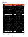
AU252XGERA combination and the data
COOLING
QUADRI(1x4)
TRI (1x3)
BI (1x2)
Co
mb. Unit
A
7
7
7
9
9
9
12
12
12
14
14
18
7
7
7
7
7
7
7
7
7
7
7
7
9
9
9
9
9
9
9
12
12
7
7
7
7
7
7
7
7
7
7
9
9
Combinations
Unit
B
12
14
18
12
14
18
12
14
18
14
18
18
7
7
7
7
7
9
9
9
9
12
12
12
9
9
9
9
12
12
12
12
12
7
7
7
7
7
7
7
7
9
9
9
9
Unit
C
—
—
—
—
—
—
—
—
—
—
—
—
7
9
12
14
18
9
12
14
18
12
14
18
9
12
14
18
12
14
18
12
14
7
7
7
7
9
9
9
12
9
9
9
9
Unit
D
—
—
—
—
—
—
—
—
—
—
—
—
—
—
—
—
—
—
—
—
—
—
—
—
—
—
—
—
—
—
—
—
—
7
9
12
14
9
12
14
12
9
12
9
12
Rated capacity(Kw)
(Nom. cooling)
Unit
Unit
Unit
Unit
A
B
C
D
2.00 3.50
—
—
2.00 4.10
—
—
2.00 5.00
—
—
2.50 3.50
—
—
2.50 4.10
—
—
2.43 4.87
—
—
3.50 3.50
—
—
3.36 3.94
—
—
3.03 4.27
—
—
3.65 3.65
—
—
3.31 3.99
—
—
3.65 3.65
—
—
2.00 2.00 2.00
—
2.00 2.00 2.50
—
1.95 1.95 3.41
—
1.83 1.83 3.65
—
1.63 1.63 4.03
—
2.00 2.50 2.50
—
1.83 2.31 3.17
—
1.73 2.11 3.46
—
1.54 1.92 3.84
—
1.63 2.83 2.83
—
1.54 2.59 3.17
—
1.44 2.40 3.46
—
2.43 2.43 2.43
—
2.16 2.16 2.98
—
2.02 2.02 3.27
—
1.83 1.83 3.65
—
1.92 2.69 2.69
—
1.83 2.50 2.98
—
1.68 2.31 3.31
—
2.43 2.43 2.43
—
2.31 2.31 2.69
—
1.83 1.83 1.83 1.83
1.73 1.73 1.73 2.11
1.54 1.54 1.54 2.69
1.44 1.44 1.44 2.98
1.63 1.63 2.02 2.02
1.44 1.44 1.83 2.59
1.39 1.39 1.73 2.79
1.34 1.34 2.31 2.31
1.54 1.92 1.92 1.92
1.39 1.73 1.73 2.45
1.83 1.83 1.83 1.83
1.68 1.68 1.68 2.26
total cooling
capacity(kW)
min. rated max.
data data data
total power input
(kW)
min. rated max.
data data Data
total current
(A)@230V
min.
rated
max.
data
data
Data
1.00
1.00
1.00
1.20
1.00
1.00
1.00
1.20
1.00
1.20
1.20
1.20
1.50
1.50
1.50
1.50
1.50
1.50
1.50
1.50
1.50
1.50
1.50
1.50
1.50
1.50
1.50
1.50
1.50
1.50
1.50
1.50
1.50
1.80
1.80
1.80
1.80
1.80
1.80
1.80
1.80
1.80
1.80
1.80
1.80
0.47
0.50
0.50
0.47
0.50
0.50
0.47
0.50
0.50
0.55
0.55
0.55
0.55
0.55
0.55
0.60
0.60
0.55
0.55
0.60
0.60
0.55
0.60
0.60
0.62
0.55
0.60
0.60
0.55
0.60
0.60
0.55
0.60
0.60
0.60
0.60
0.62
0.60
0.60
0.62
0.60
0.60
0.60
0.60
0.60
2.09
2.22
2.22
2.09
2.22
2.22
2.09
2.22
2.22
2.44
2.44
2.44
2.44
2.44
2.44
2.66
2.66
2.44
2.44
2.66
2.66
2.44
2.66
2.66
2.75
2.44
2.66
2.66
2.44
2.66
2.66
2.44
2.66
2.66
2.66
2.66
2.75
2.66
2.66
2.75
2.66
2.66
2.66
2.66
2.66
5.50
6.10
7.00
6.00
6.60
7.3
7.00
7.3
7.3
7.3
7.3
7.3
6.00
6.50
7.3
7.3
7.3
7.00
7.3
7.3
7.3
7.3
7.3
7.3
7.3
7.3
7.3
7.3
7.3
7.3
7.3
7.3
7.3
7.3
7.3
7.3
7.3
7.3
7.3
7.3
7.3
7.3
7.3
7.3
7.3
5.90
6.50
7.40
6.40
7.00
7.90
7.40
8.00
8.00
8.00
8.00
8.00
6.60
7.10
8.10
8.20
8.20
7.60
8.20
8.20
8.20
8.20
8.20
8.20
8.20
8.20
8.20
8.20
8.20
8.20
8.20
8.20
8.20
8.20
8.20
8.20
8.20
8.20
8.20
8.20
8.20
8.20
8.20
8.20
8.20
-23-
2.06
2.37
2.34
2.16
2.34
2.44
2.44
2.49
2.48
2.48
2.46
2.44
2.44
2.42
2.40
2.34
2.33
2.42
2.39
2.33
2.30
2.44
2.39
2.39
2.39
2.39
2.34
2.34
2.39
2.34
2.34
2.39
2.34
2.33
2.33
2.33
2.35
2.33
2.33
2.35
2.32
2.32
2.30
2.28
2.25
3.20
3.20
3.20
3.20
3.20
3.20
3.20
3.20
3.20
3.20
3.20
3.20
3.20
3.20
3.20
3.20
3.20
3.20
3.20
3.20
3.20
3.20
3.20
3.20
3.20
3.20
3.20
3.20
3.20
3.20
3.20
3.20
3.20
3.20
3.20
3.20
3.20
3.20
3.20
3.20
3.20
3.20
3.20
3.20
3.20
9.76
11.22
11.09
10.20
11.09
11.54
11.54
11.80
11.76
11.71
11.62
11.54
11.54
11.45
11.36
11.09
11.00
11.45
11.31
11.00
10.87
11.54
11.31
11.31
11.31
11.31
11.09
11.09
11.31
11.09
11.09
11.31
11.09
11.00
10.87
10.78
10.65
10.78
10.74
10.65
10.65
10.65
10.56
10.65
10.56
14.50
14.50
14.50
14.50
14.50
14.50
14.50
14.50
14.50
14.50
14.50
14.50
14.50
14.50
14.50
14.50
14.50
14.50
14.50
14.50
14.50
14.50
14.50
14.50
14.50
14.50
14.50
14.50
14.50
14.50
14.50
14.50
14.50
14.50
14.50
14.50
14.50
14.50
14.50
14.50
14.50
14.50
14.50
14.50
14.50
EER
(W/W)
ENERGY
LABEL
rated
capacity
2.67
2.57
2.99
2.78
2.82
2.99
2.87
2.93
2.94
2.95
2.97
2.99
2.46
2.69
3.04
3.11
3.14
2.89
3.05
3.14
3.18
2.99
3.05
3.05
3.05
3.05
3.11
3.11
3.05
3.11
3.11
3.05
3.11
3.14
3.13
3.13
3.11
3.13
3.13
3.11
3.15
3.15
3.17
3.21
3.24
D
E
C
D
C
C
C
C
C
C
C
C
E
D
B
B
B
C
B
B
B
C
B
B
B
B
B
B
B
B
B
B
B
B
B
B
B
B
B
B
B
B
B
A
A
>_]]VbTZR\ <Zb >_^UZdZ_^Vb
HEATING
QUADRI(1x4)
TRI (1x3)
BI (1x2)
Combinations
Co
mb
. Unit Unit Unit Unit
A
B
C
D
7
12
—
—
7
14
—
—
7
18
—
—
9
12
—
—
9
14
—
—
9
18
—
—
12
12
—
—
12
14
—
—
12
18
—
—
14
14
—
—
14
18
—
—
18
18
—
—
7
7
7
—
7
7
9
—
7
7
12
—
7
7
14
—
7
7
18
—
7
9
9
—
7
9
12
—
7
9
14
—
7
9
18
—
7
12
12
—
7
12
14
—
7
12
18
—
9
9
9
—
9
9
12
—
9
9
14
—
9
9
18
—
9
12
12
—
9
12
14
—
9
12
18
—
12
12
12
—
12
12
14
—
7
7
7
7
7
7
7
9
7
7
7
12
7
7
7
14
7
7
9
9
7
7
9
12
7
7
9
14
7
7
12
12
7
9
9
9
7
9
9
12
9
9
9
9
9
9
9
12
Rated capacity(kW)
(Nom. heating)
Unit
Unit
Unit
Unit
A
B
C
D
2.30 3.80
—
—
2.30 4.60
—
—
2.30 5.50
—
—
2.90 3.80
—
—
2.90 4.50
—
—
2.83 5.37
—
—
3.80 3.80
—
—
3.71 4.49
—
—
3.38 4.82
—
—
4.10 4.10
—
—
3.76 4.44
—
—
4.10 4.10
—
—
2.30 2.30 2.30
—
2.30 2.30 2.90
—
2.25 2.25 3.71
—
2.07 2.07 4.05
—
1.64 1.64 4.92
—
2.30 2.90 2.90
—
2.12 2.60 3.47
—
1.93 2.41 3.86
—
1.83 2.22 4.15
—
1.93 3.14 3.14
—
1.78 2.89 3.52
—
1.64 2.60 3.96
—
2.73 2.73 2.73
—
2.33 2.33 3.54
—
2.41 2.41 3.38
—
2.03 2.03 4.15
—
2.41 2.89 2.89
—
2.12 2.75 3.33
—
1.93 2.56 3.71
—
2.73 2.73 2.73
—
2.56 2.56 3.09
—
2.05 2.05 2.05 2.05
1.93 1.93 1.93 2.41
1.78 1.78 1.78 2.85
1.64 1.64 1.64 3.28
1.83 1.83 2.27 2.27
1.69 1.69 2.12 2.70
1.59 1.59 1.93 3.09
1.54 1.54 2.56 2.56
1.83 2.12 2.12 2.12
1.59 1.93 1.93 2.75
2.05 2.05 2.05 2.05
1.93 1.93 1.93 2.41
total heating
capacity(KW)
min. rated max.
data data data
total power input
(W)
min. rated max.
data data Data
total current
(A)@230V
min.
rated
max.
data
data
Data
1.00
1.00
1.00
1.20
1.00
1.00
1.00
1.20
1.00
1.20
1.20
1.20
1.50
1.50
1.50
1.50
1.50
1.50
1.50
1.50
1.50
1.50
1.50
1.50
1.50
1.50
1.50
1.50
1.50
1.50
1.50
1.50
1.50
1.80
1.80
1.80
1.80
1.80
1.80
1.80
1.80
1.80
1.80
1.80
1.80
0.47
0.50
0.50
0.47
0.50
0.50
0.47
0.50
0.50
0.55
0.55
0.55
0.55
0.55
0.55
0.60
0.60
0.55
0.55
0.60
0.60
0.55
0.60
0.60
0.62
0.55
0.60
0.60
0.55
0.60
0.60
0.55
0.60
0.60
0.60
0.60
0.62
0.60
0.60
0.62
0.60
0.60
0.60
0.60
0.60
2.09
2.22
2.22
2.09
2.22
2.22
2.09
2.22
2.22
2.44
2.44
2.44
2.44
2.44
2.44
2.66
2.66
2.44
2.44
2.66
2.66
2.44
2.66
2.66
2.75
2.44
2.66
2.66
2.44
2.66
2.66
2.44
2.66
2.66
2.66
2.66
2.75
2.66
2.66
2.75
2.66
2.66
2.66
2.66
2.66
6.10
6.90
7.80
6.70
7.40
8.2
7.60
8.2
8.2
8.2
8.2
8.2
6.90
7.50
8.2
8.2
8.2
8.10
8.2
8.2
8.2
8.2
8.2
8.2
8.2
8.2
8.2
8.2
8.2
8.2
8.2
8.2
8.2
8.2
8.2
8.2
8.2
8.2
8.2
8.2
8.2
8.2
8.2
8.2
8.2
6.70
7.60
8.50
7.30
8.10
9.00
8.00
9.00
9.00
9.00
9.00
9.00
7.50
8.10
9.00
9.00
9.00
8.90
9.00
9.00
9.00
9.00
9.00
9.00
9.00
9.00
9.00
9.00
9.00
9.00
9.00
9.00
9.00
9.00
9.00
9.00
9.00
9.00
9.00
9.00
9.00
9.00
9.00
9.00
9.00
-24-
2.11
2.39
2.39
2.16
2.39
2.39
2.34
2.39
2.39
2.48
2.47
2.47
2.44
2.42
2.40
2.34
2.33
2.42
2.39
2.33
2.30
2.44
2.39
2.39
2.39
2.39
2.34
2.34
2.39
2.34
2.34
2.39
2.34
2.34
2.30
2.30
2.27
2.30
2.30
2.27
2.27
2.27
2.25
2.25
2.25
3.20
3.20
3.20
3.20
3.20
3.20
3.20
3.20
3.20
3.20
3.20
3.20
3.20
3.20
3.20
3.20
3.20
3.20
3.20
3.20
3.20
3.20
3.20
3.20
3.20
3.20
3.20
3.20
3.20
3.20
3.20
3.20
3.20
3.20
3.20
3.20
3.20
3.20
3.20
3.20
3.20
3.20
3.20
3.20
3.20
9.98
11.31
11.31
10.20
11.31
11.31
11.09
11.31
11.31
11.76
11.67
11.67
11.54
11.45
11.36
11.09
11.00
11.45
11.31
11.00
10.87
11.54
11.31
11.31
11.31
11.31
11.09
11.09
11.31
11.09
11.09
11.31
11.09
11.09
10.87
10.87
10.74
10.87
10.87
10.74
10.74
10.74
10.65
10.65
10.65
14.50
14.50
14.50
14.50
14.50
14.50
14.50
14.50
14.50
14.50
14.50
14.50
14.50
14.50
14.50
14.50
14.50
14.50
14.50
14.50
14.50
14.50
14.50
14.50
14.50
14.50
14.50
14.50
14.50
14.50
14.50
14.50
14.50
14.50
14.50
14.50
14.50
14.50
14.50
14.50
14.50
14.50
14.50
14.50
14.50
ENERGY
COP
LABEL
(W/W)
rated
capacity
2.89
D
2.89
D
3.26
C
3.11
C
3.10
C
3.43
B
3.24
C
3.43
B
3.43
B
3.30
C
3.33
C
3.33
C
2.83
D
3.10
C
3.42
B
3.50
B
3.53
B
3.35
C
3.43
B
3.53
B
3.57
B
3.36
C
3.43
B
3.43
B
3.43
B
3.43
B
3.50
B
3.50
B
3.43
B
3.50
B
3.50
B
3.43
B
3.50
B
3.50
B
3.57
B
3.57
B
3.61
A
3.57
B
3.57
B
3.61
A
3.61
A
3.61
A
3.64
A
3.64
A
3.64
A
>_]]VbTZR\ <Zb >_^UZdZ_^Vb
AU282XHERA combination and the data
COOLING
QUADRI(1x4)
TRI (1x3)
BI (1x2)
Co
mb. Unit
A
7
7
9
9
9
12
12
12
14
14
18
7
7
7
7
7
7
7
7
7
7
7
7
7
7
9
9
9
9
9
9
9
9
9
12
12
12
12
7
7
7
7
7
7
7
7
7
7
7
7
7
7
7
7
9
9
9
9
Combinations
Unit
B
14
18
12
14
18
12
14
18
14
18
18
7
7
7
7
7
9
9
9
9
12
12
12
14
14
9
9
9
9
12
12
12
14
14
12
12
12
14
7
7
7
7
7
7
7
7
7
7
7
9
9
9
9
9
9
9
9
9
Unit
C
—
—
—
—
—
—
—
—
—
—
—
7
9
12
14
18
9
12
14
18
12
14
18
14
18
9
12
14
18
12
14
18
14
18
12
14
18
14
7
7
7
7
7
9
9
9
9
12
12
9
9
9
12
12
9
9
9
12
Unit
D
—
—
—
—
—
—
—
—
—
—
—
—
—
—
—
—
—
—
—
—
—
—
—
—
—
—
—
—
—
—
—
—
—
—
—
—
—
—
7
9
12
14
18
9
12
14
18
12
14
9
12
14
12
14
9
12
14
12
Rated capacity Output/kW
(Nom. cooling)
Unit
Unit
Unit
Unit
A
B
C
D
2.00 4.10
—
—
2.00 5.00
—
—
2.50 3.50
—
—
2.50 4.10
—
—
2.50 5.00
—
—
3.50 3.50
—
—
3.50 4.10
—
—
3.05 4.95
—
—
4.00 4.00
—
—
3.50 4.50
—
—
4.00 4.00
—
—
2.00 2.00 2.00
—
2.00 2.00 2.50
—
2.00 2.00 3.50
—
2.00 2.00 4.00
—
1.75 1.75 4.50
—
2.00 2.00 2.50
—
2.00 2.50 3.50
—
1.90 2.30 3.80
—
1.70
2.10 4.20
—
1.85 3.05 3.05
—
1.70 2.90 3.40
—
1.60 2.60 3.80
—
1.55 3.20 3.20
—
1.40 3.00 3.60
—
2.5
2.5
2.5
—
2.44 2.44 3.12
—
2.20 2.20 3.60
—
2.0
2.0
4.0
—
2.26 2.87 2.87
—
2.05 2.60 3.35
—
1.80 2.50 3.70
—
1.90 3.05 3.05
—
1.70 2.90 3.40
—
2.65 2.65 2.65
—
2.45 2.45 3.10
—
2.20 2.20 3.60
—
2.25 2.85 2.85
—
2.0
2.0
2.0
2.0
1.90 1.90 1.90 2.30
1.75 1.75 1.75 2.75
1.60 1.60 1.60 3.20
1.45 1.45 1.45 3.65
1.75 1.75 2.25 2.25
1.70 1.70 2.10 2.50
1.50 1.50 1.90 3.10
1.40 1.40 1.70 3.50
1.45 1.45 2.55 2.55
1.40 1.40 2.40 2.80
1.70
2.10 2.10 2.10
1.60 2.00 2.00 2.40
1.45 1.80 1.80 2.95
1.40 1.70 2.45 2.45
1.30 1.65 2.30 2.75
2.00 2.00 2.00 2.00
1.90 1.90 1.90 2.30
1.70 1.70 1.70 2.90
1.65 1.65 2.05 2.65
total cooling
capacity(kW)
min. rated max.
data data data
total power input
(kW)
min. rated max.
data data Data
total current
(A)@230V
min.
rated
max.
data
data
Data
1.00
1.00
1.00
1.00
1.00
1.00
1.00
1.00
1.00
1.00
1.00
1.50
1.50
1.50
1.50
1.50
1.50
1.50
1.50
1.50
1.50
1.50
1.50
1.50
1.50
1.50
1.50
1.50
1.50
1.50
1.50
1.50
1.50
1.50
1.50
1.50
1.50
1.50
1.80
1.80
1.80
1.80
1.80
1.80
1.80
1.80
1.80
1.80
1.80
1.80
1.80
1.80
1.80
1.80
1.80
1.80
1.80
1.80
0.50
0.50
0.50
0.50
0.50
0.50
0.50
0.50
0.55
0.55
0.55
0.55
0.55
0.55
0.55
0.55
0.55
0.55
0.55
0.55
0.55
0.55
0.55
0.55
0.55
0.55
0.55
0.55
0.55
0.55
0.55
0.55
0.55
0.55
0.55
0.55
0.55
0.55
0.65
0.65
0.65
0.65
0.65
0.65
0.65
0.65
0.65
0.65
0.65
0.65
0.65
0.65
0.65
0.65
0.65
0.65
0.65
0.65
2.15
2.15
2.15
2.15
2.15
2.15
2.15
2.15
2.50
2.50
2.50
2.50
2.50
2.50
2.50
2.50
2.50
2.50
2.50
2.50
2.50
2.50
2.50
2.50
2.50
2.50
2.50
2.50
2.50
2.50
2.50
2.50
2.50
2.50
2.50
2.50
2.50
2.50
2.85
2.85
2.85
2.85
2.85
2.85
2.85
2.85
2.85
2.85
2.85
2.85
2.85
2.85
2.85
2.85
2.85
2.85
2.85
2.85
6.10
7.00
6.00
6.60
7.50
7.00
7.60
8.00
8.00
8.00
8.00
6.00
6.50
7.50
8.00
8.00
6.50
8.00
8.00
8.00
7.95
8.00
8.00
7.95
8.00
7.50
8.00
8.00
8.00
8.00
8.00
8.00
8.00
8.00
7.95
8.00
8.00
7.95
8.00
8.00
8.00
8.00
8.00
8.00
8.00
8.00
8.00
8.00
8.00
8.00
8.00
8.00
8.00
8.00
8.00
8.00
8.00
8.00
6.50
7.40
6.40
7.00
7.90
6.80
8.00
8.40
8.60
8.60
8.60
6.60
7.10
8.10
8.70
8.80
7.10
8.60
8.70
8.80
8.60
8.70
8.80
8.80
8.90
8.10
8.60
8.70
8.80
8.60
8.70
8.80
8.80
8.90
8.50
8.70
8.80
8.80
9.20
9.20
9.20
9.30
9.50
9.20
9.20
9.30
9.50
9.20
9.30
9.20
9.20
9.30
9.20
9.30
9.20
9.20
9.30
9.40
-25-
2.20
2.45
2.35
2.20
2.50
2.25
2.60
2.60
2.70
2.70
2.70
2.70
2.70
2.70
2.70
2.70
2.70
2.70
2.70
2.65
2.70
2.70
2.65
2.65
2.65
2.65
2.65
2.65
2.65
2.65
2.65
2.65
2.65
2.65
2.65
2.65
2.65
2.65
2.60
2.60
2.60
2.60
2.60
2.60
2.60
2.60
2.60
2.55
2.55
2.60
2.55
2.55
2.50
2.50
2.55
2.50
2.50
2.50
3.80
3.80
3.80
3.80
3.80
3.80
3.80
3.80
3.80
3.80
3.80
3.80
3.80
3.80
3.80
3.80
3.80
3.80
3.80
3.80
3.80
3.80
3.80
3.80
3.80
3.80
3.80
3.80
3.80
3.80
3.80
3.80
3.80
3.80
3.80
3.80
3.80
3.80
3.80
3.80
3.80
3.80
3.80
3.80
3.80
3.80
3.80
3.80
3.80
3.80
3.80
3.80
3.80
3.80
3.80
3.80
3.80
3.80
9.76
10.87
10.43
9.76
11.09
9.98
11.54
11.54
11.98
11.98
11.98
11.98
11.98
11.98
11.98
11.98
11.98
11.98
11.98
11.76
11.98
11.98
11.76
11.76
11.76
11.76
11.76
11.76
11.76
11.76
11.76
11.76
11.76
11.76
11.76
11.76
11.76
11.76
11.54
11.54
11.54
11.54
11.54
11.54
11.54
11.54
11.54
11.31
11.31
11.54
11.31
11.31
11.09
11.09
11.31
11.09
11.09
11.09
16.80
16.80
16.80
16.80
16.80
16.80
16.80
16.80
16.80
16.80
16.80
16.80
16.80
16.80
16.80
16.80
16.80
16.80
16.80
16.80
16.80
16.80
16.80
16.80
16.80
16.80
16.80
16.80
16.80
16.80
16.80
16.80
16.80
16.80
16.80
16.80
16.80
16.80
16.80
16.80
16.80
16.80
16.80
16.80
16.80
16.80
16.80
16.80
16.80
16.80
16.80
16.80
16.80
16.80
16.80
16.80
16.80
16.80
ENERGY
EER
LABEL
(W/W)
rated
capacity
2.77
D
2.86
C
2.55
E
3.00
B
3.00
B
3.11
B
2.92
C
3.08
B
2.96
C
2.96
C
2.96
C
2.22
F
2.41
E
2.78
D
2.96
C
2.96
C
2.41
E
2.96
C
2.96
C
3.02
B
2.94
C
2.96
C
3.02
B
3.00
B
3.02
B
2.83
C
3.02
B
3.02
B
3.02
B
3.02
B
3.02
B
3.02
B
3.02
B
3.02
B
3.00
B
3.02
B
3.02
B
3.00
B
3.08
B
3.08
B
3.08
B
3.08
B
3.08
B
3.08
B
3.08
B
3.08
B
3.08
B
3.14
B
3.14
B
3.08
B
3.14
B
3.14
B
3.20
B
3.20
B
3.14
B
3.20
B
3.20
B
3.20
B
>_]]VbTZR\ <Zb >_^UZdZ_^Vb
HEATING
QUADRI(1x4)
TRI (1x3)
BI (1x2)
Co
mb. Unit
A
7
7
9
9
9
12
12
12
14
14
18
7
7
7
7
7
7
7
7
7
7
7
7
7
7
9
9
9
9
9
9
9
9
9
12
12
12
12
7
7
7
7
7
7
7
7
7
7
7
7
7
7
7
7
9
9
9
9
Combinations
Unit
B
14
18
12
14
18
12
14
18
14
18
18
7
7
7
7
7
9
9
9
9
12
12
12
14
14
9
9
9
9
12
12
12
14
14
12
12
12
14
7
7
7
7
7
7
7
7
7
7
7
9
9
9
9
9
9
9
9
9
Unit
C
—
—
—
—
—
—
—
—
—
—
—
7
9
12
14
18
9
12
14
18
12
14
18
14
18
9
12
14
18
12
14
18
14
18
12
14
18
14
7
7
7
7
7
9
9
9
9
12
12
9
9
9
12
12
9
9
9
12
Unit
D
—
—
—
—
—
—
—
—
—
—
—
—
—
—
—
—
—
—
—
—
—
—
—
—
—
—
—
—
—
—
—
—
—
—
—
—
—
—
7
9
12
14
18
9
12
14
18
12
14
9
12
14
12
14
9
12
14
12
Rated capacity Output/kW
(Nom. heating)
Unit
Unit
Unit
Unit
A
B
C
D
2.30 4.60
—
—
2.30 5.50
—
—
2.90 3.80
—
—
2.90 4.60
—
—
2.90 5.50
—
—
3.80 3.80
—
—
3.80 4.60
—
—
3.80 5.50
—
—
4.60 4.60
—
—
4.60 5.40
—
—
5.00 5.00
—
—
2.30 2.30 2.30
—
2.30 2.30 2.90
—
2.30 2.30 3.80
—
2.30 2.30 4.60
—
2.30 2.30 5.40
—
2.30 2.90 2.90
—
2.30 2.90 3.80
—
2.30 2.90 4.60
—
2.15 2.70 5.15
—
2.30 3.80 3.80
—
2.15 3.55 4.30
—
2.00 3.25 4.75
—
2.00 4.00 4.00
—
1.90 3.70 4.40
—
2.90 2.90 2.90
—
2.90 2.90 3.80
—
2.75 2.75 4.50
—
2.50 2.50 5.00
—
2.80 3.60 3.60
—
2.55 3.35 4.10
—
2.40 3.10 4.50
—
2.40 3.80 3.80
—
2.25 3.55 4.20
—
3.35 3.35 3.35
—
3.10 3.10 3.80
—
2.90 2.90 4.20
—
2.90 3.55 3.55
—
2.30 2.30 2.30 2.30
2.30 2.30 2.30 2.90
2.15 2.15 2.15 3.55
2.00 2.00 2.00 4.00
1.85 1.85 1.85 4.45
2.20 2.20 2.80 2.80
2.05 2.05 2.55 3.35
1.90 1.90 2.40 3.80
1.75 1.75 2.20 4.30
1.90 1.90 3.10 3.10
1.75 1.75 2.90 3.60
2.10 2.65 2.65 2.65
1.95 2.45 2.45 3.15
1.80 2.25 2.25 3.70
1.95 2.25 2.90 2.90
1.70 2.15 2.80 3.35
2.50 2.50 2.50 2.50
2.30 2.30 2.30 3.10
2.20 2.20 2.20 3.40
2.15 2.15 2.85 2.85
total heating
capacity(KW)
min.
rated
max.
data
data
data
total power input
(W)
min. rated max.
data data Data
total current
(A)@230V
min.
rated
max.
data
data
Data
1.20
1.20
1.20
1.20
1.20
1.20
1.20
1.20
1.20
1.20
1.20
1.50
1.50
1.50
1.50
1.50
1.50
1.50
1.50
1.50
1.50
1.50
1.50
1.50
1.50
1.50
1.50
1.50
1.50
1.50
1.50
1.50
1.50
1.50
1.50
1.50
1.50
1.50
1.80
1.80
1.80
1.80
1.80
1.80
1.80
1.80
1.80
1.80
1.80
1.80
1.80
1.80
1.80
1.80
1.80
1.80
1.80
1.80
0.50
0.50
0.50
0.50
0.50
0.50
0.50
0.50
0.55
0.55
0.55
0.55
0.55
0.55
0.55
0.55
0.55
0.55
0.55
0.55
0.55
0.55
0.55
0.55
0.55
0.55
0.55
0.55
0.55
0.55
0.55
0.55
0.55
0.55
0.55
0.55
0.55
0.55
0.65
0.65
0.65
0.65
0.65
0.65
0.65
0.65
0.65
0.65
0.65
0.65
0.65
0.65
0.65
0.65
0.65
0.65
0.65
0.65
2.15
2.15
2.15
2.15
2.15
2.15
2.15
2.15
2.50
2.50
2.50
2.50
2.50
2.50
2.50
2.50
2.50
2.50
2.50
2.50
2.50
2.50
2.50
2.50
2.50
2.50
2.50
2.50
2.50
2.50
2.50
2.50
2.50
2.50
2.50
2.50
2.50
2.50
2.85
2.85
2.85
2.85
2.85
2.85
2.85
2.85
2.85
2.85
2.85
2.85
2.85
2.85
2.85
2.85
2.85
2.85
2.85
2.85
6.90
7.80
6.70
7.50
8.40
7.60
8.40
9.30
9.20
10.00
10.00
6.90
7.50
8.40
9.20
10.00
8.10
9.00
9.80
10.00
9.90
10.00
10.00
10.00
10.00
8.70
9.60
10.00
10.00
10.00
10.00
10.00
10.00
10.00
10.05
10.00
10.00
10.00
9.20
9.80
10.00
10.00
10.00
10.00
10.00
10.00
10.00
10.00
10.00
10.05
10.00
10.00
10.00
10.00
10.00
10.00
10.00
10.00
7.50
8.40
7.30
8.20
9.20
8.20
9.10
10.20
10.20
10.50
11.00
7.80
8.40
9.30
10.20
10.50
10.50
10.50
10.50
11.00
10.80
11.00
11.00
11.00
11.00
10.50
10.50
10.50
11.50
11.50
11.50
11.50
11.50
11.50
11.50
11.50
11.50
11.50
10.50
10.50
11.50
11.50
11.50
11.50
11.50
11.50
11.50
11.50
11.50
11.50
11.50
11.50
11.50
11.50
11.50
11.50
11.50
11.50
-26-
2.80
2.90
2.90
3.00
3.00
2.95
2.90
3.10
3.00
3.00
3.00
2.85
2.85
2.85
2.80
2.80
2.90
2.90
2.80
2.85
2.90
2.90
2.90
2.85
2.85
2.90
2.90
2.85
2.80
2.80
2.80
2.85
2.90
2.90
2.95
2.90
2.90
2.90
2.90
2.90
2.85
2.85
2.85
2.90
2.90
2.85
2.85
2.90
2.85
2.90
2.90
2.85
2.80
2.80
2.75
2.75
2.75
2.70
3.80
3.80
3.80
3.80
3.80
3.80
3.80
3.80
3.80
3.80
3.80
3.80
3.80
3.80
3.80
3.80
3.80
3.80
3.80
3.80
3.80
3.80
3.80
3.80
3.80
3.80
3.80
3.80
3.80
3.80
3.80
3.80
3.80
3.80
3.80
3.80
3.80
3.80
3.80
3.80
3.80
3.80
3.80
3.80
3.80
3.80
3.80
3.80
3.80
3.80
3.80
3.80
3.80
3.80
3.80
3.80
3.80
3.80
12.42
12.87
12.87
13.31
13.31
13.09
12.87
13.75
13.31
13.31
13.31
12.64
12.64
12.64
12.42
12.42
12.87
12.87
12.42
12.64
12.87
12.87
12.87
12.64
12.64
12.87
12.87
12.64
12.42
12.42
12.42
12.64
12.87
12.87
13.09
12.87
12.87
12.87
12.87
12.87
12.64
12.64
12.64
12.87
12.87
12.64
12.64
12.87
12.64
12.87
12.87
12.64
12.42
12.42
12.20
12.20
12.20
11.98
16.80
16.80
16.80
16.80
16.80
16.80
16.80
16.80
16.80
16.80
16.80
16.80
16.80
16.80
16.80
16.80
16.80
16.80
16.80
16.80
16.80
16.80
16.80
16.80
16.80
16.80
16.80
16.80
16.80
16.80
16.80
16.80
16.80
16.80
16.80
16.80
16.80
16.80
16.80
16.80
16.80
16.80
16.80
16.80
16.80
16.80
16.80
16.80
16.80
16.80
16.80
16.80
16.80
16.80
16.80
16.80
16.80
16.80
ENERGY
EER
LABEL
(W/W)
rated
capacity
2.46
F
2.69
E
2.31
G
2.50
F
2.80
D
2.58
F
2.90
D
3.00
C
3.07
C
3.33
C
3.33
C
2.42
F
2.63
E
2.95
D
3.29
C
3.57
B
2.79
E
3.10
C
3.50
B
3.51
B
3.41
B
3.45
B
3.45
B
3.51
B
3.51
B
3.00
C
3.31
C
3.51
B
3.57
B
3.57
B
3.57
B
3.51
B
3.45
B
3.45
B
3.41
B
3.45
B
3.45
B
3.45
B
3.17
C
3.38
C
3.51
B
3.51
B
3.51
B
3.45
B
3.45
B
3.51
B
3.51
B
3.45
B
3.51
B
3.47
B
3.45
B
3.51
B
3.57
B
3.57
B
3.64
A
3.64
A
3.64
A
3.70
A
>_]]VbTZR\ <Zb >_^UZdZ_^Vb
AU342XHERA combination and the data
COOLING
QUADRI(1x4)
TRI (1x3)
BI (1x2)
Combinations
Co
mb
Unit
Unit Unit Unit
.
A
B
C
D
7
18
—
—
9
18
—
—
12
14
—
—
12
18
—
—
14
14
—
—
14
18
—
—
18
18
—
—
7
7
12
—
7
7
14
—
7
7
18
—
7
9
9
—
7
9
12
—
7
9
14
—
7
9
18
—
7
12
12
—
7
12
14
—
7
12
18
—
9
9
9
—
9
9
12
—
9
9
14
—
9
9
18
—
9
12
12
—
9
12
14
—
9
12
18
—
12
12
12
—
12
12
14
—
12
12
18
—
7
7
7
7
7
7
7
9
7
7
7
12
7
7
7
14
7
7
7
18
7
7
9
9
7
7
9
12
7
7
9
14
7
7
9
18
7
7
12
12
7
7
12
14
7
7
12
18
7
9
9
9
7
9
9
12
7
9
9
14
7
9
9
18
7
9
12
12
7
9
12
14
7
9
12
18
7
12
12
12
7
12
12
14
9
9
9
9
9
9
9
12
9
9
9
14
9
9
9
18
9
9
12
12
9
9
12
14
9
9
12
18
9
12
12
12
9
12
12
14
12
12
12
12
Rated capacity Output/kW
(Nom. cooling)
Unit
Unit
Unit
Unit
A
B
C
D
2.00 5.00
—
—
2.50 5.00
—
—
3.50 4.10
—
—
3.50 5.00
—
—
4.10 4.10
—
—
4.10 5.00
—
—
5.00 5.00
—
—
2.00 2.00 3.50
—
2.00 2.00 4.10
—
2.00 2.00 5.00
—
2.00 2.50 2.50
—
2.00 2.50 3.50
—
2.00 2.50 4.10
—
2.00 2.50 5.00
—
2.00 3.50 3.50
—
2.00 3.50 4.10
—
1.90 3.30 4.80
—
2.50 2.50 2.50
—
2.50 2.50 3.50
—
2.50 2.50 4.10
—
2.50 2.50 5.00
—
2.50 3.50 3.50
—
2.45 3.45 4.10
—
2.30 3.20 4.50
—
3.33 3.33 3.33
—
3.15 3.15 3.70
—
2.90 2.90 4.20
—
2.00 2.00 2.00 2.00
2.00 2.00 2.00 2.50
2.00 2.00 2.00 3.50
1.95 1.95 1.95 4.10
1.85 1.85 1.85 4.45
2.00 2.00 2.50 2.50
2.00 2.00 2.50 3.50
1.85 1.85 2.35 3.95
1.75 1.75 2.15 4.35
1.80 1.80 3.20 3.20
1.70 1.70 3.00 3.60
1.60 1.60 2.80 4.00
2.00 2.50 2.50 2.50
1.90 2.40 2.40 3.30
1.80 2.25 2.25 3.70
1.70 2.10 2.10 4.10
1.75 2.15 3.05 3.05
1.65 2.05 2.90 3.40
1.55 1.95 2.70 3.80
1.60 2.80 2.80 2.80
1.55 2.70 2.70 3.05
2.50 2.50 2.50 2.50
2.30 2.30 2.30 3.10
2.15 2.15 2.15 3.55
2.00 2.00 2.00 4.00
2.10 2.10 2.90 2.90
2.00 2.00 2.75 3.25
1.85 1.85 2.60 3.70
1.90 2.70 2.70 2.70
1.85 2.50 2.50 3.15
2.50 2.50 2.50 2.50
total cooling
capacity(kW)
min.
rated
max.
data
data
data
total power input
(kW)
min. rated max.
data data Data
total current
(A)@230V
min.
rated
max.
data
data
Data
1.00
1.00
1.00
1.00
1.00
1.00
1.00
1.50
1.50
1.50
1.50
1.50
1.50
1.50
1.50
1.50
1.50
1.50
1.50
1.50
1.50
1.50
1.50
1.50
1.50
1.50
1.50
1.80
1.80
1.80
1.80
1.80
1.80
1.80
1.80
1.80
1.80
1.80
1.80
1.80
1.80
1.80
1.80
1.80
1.80
1.80
1.80
1.80
1.80
1.80
1.80
1.80
1.80
1.80
1.80
1.80
1.80
1.80
0.50
0.50
0.50
0.50
0.50
0.50
0.50
0.55
0.55
0.55
0.55
0.55
0.55
0.55
0.55
0.55
0.55
0.55
0.55
0.55
0.55
0.55
0.55
0.55
0.55
0.55
0.55
0.65
0.65
0.65
0.65
0.65
0.65
0.65
0.65
0.65
0.65
0.65
0.65
0.65
0.65
0.65
0.65
0.65
0.65
0.65
0.65
0.65
0.65
0.65
0.65
0.65
0.65
0.65
0.65
0.65
0.65
0.65
2.15
2.15
2.15
2.15
2.15
2.15
2.15
2.50
2.50
2.50
2.50
2.50
2.50
2.50
2.50
2.50
2.50
2.50
2.50
2.50
2.50
2.50
2.50
2.50
2.50
2.50
2.50
2.85
2.85
2.85
2.85
2.85
2.85
2.85
2.85
2.85
2.85
2.85
2.85
2.85
2.85
2.85
2.85
2.85
2.85
2.85
2.85
2.85
2.85
2.85
2.85
2.85
2.85
2.85
2.85
2.85
2.85
2.85
7.00
7.50
7.60
8.50
8.20
9.10
10.00
7.50
8.10
9.00
7.00
8.00
8.60
9.50
9.00
9.60
10.00
7.50
8.50
9.10
10.00
9.50
10.00
10.00
10.00
10.00
10.00
8.00
8.50
9.50
9.95
10.00
9.00
10.00
10.00
10.00
10.00
10.00
10.00
9.50
10.00
10.00
10.00
10.00
10.00
10.00
10.00
10.00
10.00
10.00
10.00
10.00
10.00
10.00
10.00
10.00
10.00
10.00
7.50
8.00
8.10
9.00
8.80
9.70
10.50
8.10
8.80
9.80
7.60
8.60
9.30
10.20
9.60
10.20
10.50
8.10
9.10
9.80
10.50
10.20
10.50
10.50
10.50
10.50
10.50
8.80
9.30
10.30
10.80
11.00
9.80
10.50
10.80
11.00
10.80
10.90
11.00
10.30
10.80
10.90
11.00
10.80
10.90
11.00
11.00
11.00
11.00
11.00
11.00
11.00
11.00
11.00
11.00
11.00
11.00
11.00
-27-
2.85
2.90
2.90
3.30
3.30
3.50
3.50
3.10
3.20
3.25
3.10
3.10
3.15
3.40
3.40
3.40
3.40
3.40
3.40
3.35
3.35
3.40
3.38
3.38
3.40
3.38
3.38
3.25
3.25
3.25
3.30
3.30
3.25
3.25
3.30
3.30
3.25
3.30
3.30
3.25
3.28
3.25
3.25
3.25
3.22
3.20
3.22
3.22
3.30
3.25
3.24
3.23
3.20
3.17
3.15
3.17
3.17
3.17
4.00
4.00
4.00
4.00
4.00
4.00
4.00
4.00
4.00
4.00
4.00
4.00
4.00
4.00
4.00
4.00
4.00
4.00
4.00
4.00
4.00
4.00
4.00
4.00
4.00
4.00
4.00
4.00
4.00
4.00
4.00
4.00
4.00
4.00
4.00
4.00
4.00
4.00
4.00
4.00
4.00
4.00
4.00
4.00
4.00
4.00
4.00
4.00
4.00
4.00
4.00
4.00
4.00
4.00
4.00
4.00
4.00
4.00
12.64
12.87
12.87
14.64
14.64
15.53
15.53
13.75
14.20
14.42
13.75
13.75
13.98
15.08
15.08
15.08
15.08
15.08
15.08
14.86
14.86
15.08
15.00
15.00
15.08
15.00
15.00
14.42
14.42
14.42
14.64
14.64
14.42
14.42
14.64
14.64
14.42
14.64
14.64
14.42
14.55
14.42
14.42
14.42
14.29
14.20
14.29
14.29
14.64
14.42
14.37
14.33
14.20
14.06
13.98
14.06
14.06
14.06
18.10
18.10
18.10
18.10
18.10
18.10
18.10
18.10
18.10
18.10
18.10
18.10
18.10
18.10
18.10
18.10
18.10
18.10
18.10
18.10
18.10
18.10
18.10
18.10
18.10
18.10
18.10
18.10
18.10
18.10
18.10
18.10
18.10
18.10
18.10
18.10
18.10
18.10
18.10
18.10
18.10
18.10
18.10
18.10
18.10
18.10
18.10
18.10
18.10
18.10
18.10
18.10
18.10
18.10
18.10
18.10
18.10
18.10
ENERGY
EER
LABEL
(W/W)
rated
capacity
2.46
E
2.59
E
2.62
D
2.58
E
2.48
E
2.60
D
2.86
C
2.42
E
2.53
E
2.77
D
2.26
F
2.58
E
2.73
D
2.79
D
2.65
D
2.82
C
2.94
C
2.21
F
2.50
E
2.72
D
2.99
C
2.79
D
2.96
C
2.96
C
2.94
C
2.96
C
2.96
C
2.46
E
2.62
D
2.92
C
3.02
B
3.03
B
2.77
D
3.08
B
3.03
B
3.03
B
3.08
B
3.03
B
3.03
B
2.92
C
3.05
B
3.08
B
3.08
B
3.08
B
3.11
B
3.13
B
3.11
B
3.11
B
3.03
B
3.08
B
3.09
B
3.10
B
3.13
B
3.15
B
3.17
B
3.15
B
3.15
B
3.15
B
>_]]VbTZR\ <Zb >_^UZdZ_^Vb
HEATING
QUADRI(1x4)
TRI (1x3)
BI (1x2)
Co
mb. Unit
A
7
9
12
12
14
14
18
7
7
7
7
7
7
7
7
7
7
9
9
9
9
9
9
9
12
12
12
7
7
7
7
7
7
7
7
7
7
7
7
7
7
7
7
7
7
7
7
7
9
9
9
9
9
9
9
9
9
12
Combinations
Unit
B
18
18
14
18
14
18
18
7
7
7
9
9
9
9
12
12
12
9
9
9
9
12
12
12
12
12
12
7
7
7
7
7
7
7
7
7
7
7
7
9
9
9
9
9
9
9
12
12
9
9
9
9
9
9
9
12
12
12
Unit
C
—
—
—
—
—
—
—
12
14
18
9
12
14
18
12
14
18
9
12
14
18
12
14
18
12
14
18
7
7
7
7
7
9
9
9
9
12
12
12
9
9
9
9
12
12
12
12
12
9
9
9
9
12
12
12
12
12
12
Unit
D
—
—
—
—
—
—
—
—
—
—
—
—
—
—
—
—
—
—
—
—
—
—
—
—
—
—
—
7
9
12
14
18
9
12
14
18
12
14
18
9
12
14
18
12
14
18
12
14
9
12
14
18
12
14
18
12
14
12
Rated capacity Output/kW
(Nom. heating)
Unit
Unit
Unit
Unit
A
B
C
D
2.30 5.50
—
—
2.90 5.50
—
—
3.80 4.60
—
—
3.80 5.50
—
—
4.60 4.60
—
—
4.60 5.50
—
—
5.50 5.50
—
—
2.30 2.30 3.80
—
2.30 2.30 4.60
—
2.30 2.30 5.50
—
2.30 2.90 2.90
—
2.30 2.90 3.80
—
2.30 2.90 4.60
—
2.30 2.90 5.50
—
2.30 3.80 3.80
—
2.30 3.80 4.60
—
2.10 3.60 5.30
—
2.90 2.90 2.90
—
2.90 2.90 3.80
—
2.90 2.90 4.60
—
2.80 2.80 5.40
—
2.90 3.80 3.80
—
2.70 3.80 4.50
—
2.55 3.55 4.90
—
3.66 3.66 3.66
—
3.45 3.45 4.10
—
3.20 3.20 4.60
—
2.30 2.30 2.30 2.30
2.30 2.30 2.30 2.90
2.30 2.30 2.30 3.80
2.20 2.20 2.20 4.40
2.05 2.05 2.05 4.85
2.30 2.30 2.90 2.90
2.25 2.25 2.85 3.65
2.10 2.10 2.65 4.15
1.95 1.95 2.35 4.75
2.00 2.00 3.50 3.50
1.90 1.90 3.30 3.90
1.75 1.75 3.10 4.40
2.30 2.90 2.90 2.90
2.10 2.65 2.65 3.60
2.00 2.50 2.50 4.00
1.85 2.30 2.30 4.55
2.00 2.30 3.35 3.35
1.80 2.25 3.20 3.75
1.70 2.15 2.95 4.20
1.70 3.10 3.10 3.10
1.70 3.00 3.00 3.30
2.75 2.75 2.75 2.75
2.55 2.55 2.55 3.35
2.35 2.35 2.35 3.95
2.20 2.20 2.20 4.40
2.30 2.30 3.20 3.20
2.20 2.20 3.00 3.60
2.05 2.05 2.85 4.05
2.00 3.00 3.00 3.00
2.00 2.75 2.75 3.50
2.75 2.75 2.75 2.75
total heating
capacity(KW)
min.
rated
max.
data
data
data
total power input
(W)
min. rated max.
data data Data
total current
(A)@230V
min.
rated
max.
data
data
Data
1.20
1.20
1.20
1.20
1.20
1.20
1.20
1.20
1.20
1.20
1.20
1.50
1.50
1.50
1.50
1.50
1.50
1.50
1.50
1.50
1.50
1.50
1.50
1.50
1.50
1.50
1.50
1.50
1.50
1.80
1.80
1.80
1.80
1.80
1.80
1.80
1.80
1.80
1.80
1.80
1.80
1.80
1.80
1.80
1.80
1.80
1.80
1.80
1.80
1.80
1.80
1.80
1.80
1.80
1.80
1.80
1.80
1.80
0.50
0.50
0.50
0.50
0.50
0.50
0.50
0.55
0.55
0.55
0.55
0.55
0.55
0.55
0.55
0.55
0.55
0.55
0.55
0.55
0.55
0.55
0.55
0.55
0.55
0.55
0.55
0.65
0.65
0.65
0.65
0.65
0.65
0.65
0.65
0.65
0.65
0.65
0.65
0.65
0.65
0.65
0.65
0.65
0.65
0.65
0.65
0.65
0.65
0.65
0.65
0.65
0.65
0.65
0.65
0.65
0.65
0.65
2.15
2.15
2.15
2.15
2.15
2.15
2.15
2.50
2.50
2.50
2.50
2.50
2.50
2.50
2.50
2.50
2.50
2.50
2.50
2.50
2.50
2.50
2.50
2.50
2.50
2.50
2.50
2.85
2.85
2.85
2.85
2.85
2.85
2.85
2.85
2.85
2.85
2.85
2.85
2.85
2.85
2.85
2.85
2.85
2.85
2.85
2.85
2.85
2.85
2.85
2.85
2.85
2.85
2.85
2.85
2.85
2.85
2.85
7.80
8.40
8.40
9.30
9.20
10.10
11.00
8.40
9.20
10.10
8.10
9.00
9.80
10.70
9.90
10.70
11.00
8.70
9.60
10.40
11.00
10.50
11.00
11.00
11.00
11.00
11.00
9.20
9.80
10.70
11.00
11.00
10.40
11.00
11.00
11.00
11.00
11.00
11.00
11.00
11.00
11.00
11.00
11.00
11.00
11.00
11.00
11.00
11.00
11.00
11.00
11.00
11.00
11.00
11.00
11.00
11.00
11.00
7.50
8.40
7.30
8.20
9.20
8.20
9.10
10.20
10.20
10.50
11.00
7.80
8.40
9.30
10.20
10.50
10.50
10.80
11.00
11.00
11.00
11.00
11.00
10.50
11.50
11.50
11.50
11.50
11.50
10.50
10.50
11.50
11.50
11.50
11.50
11.50
11.50
11.50
11.50
11.50
11.50
11.50
11.50
11.50
11.50
11.50
11.50
11.50
11.50
11.50
11.50
11.50
11.50
11.50
11.50
11.50
11.50
11.50
-28-
2.95
3.00
3.00
3.30
3.30
3.45
3.45
2.95
2.90
2.95
2.95
2.95
3.00
3.05
2.95
3.00
3.05
3.00
3.05
3.10
3.10
3.05
3.10
3.15
3.45
3.40
3.40
3.25
3.25
3.25
3.30
3.30
3.25
3.25
3.30
3.30
3.25
3.30
3.30
3.25
3.28
3.25
3.25
3.25
3.22
3.20
3.22
3.22
3.30
3.25
3.24
3.23
3.20
3.17
3.15
3.15
3.15
3.15
4.00
4.00
4.00
4.00
4.00
4.00
4.00
4.00
4.00
4.00
4.00
4.00
4.00
4.00
4.00
4.00
4.00
4.00
4.00
4.00
4.00
4.00
4.00
4.00
4.00
4.00
4.00
4.00
4.00
4.00
4.00
4.00
4.00
4.00
4.00
4.00
4.00
4.00
4.00
4.00
4.00
4.00
4.00
4.00
4.00
4.00
4.00
4.00
4.00
4.00
4.00
4.00
4.00
4.00
4.00
4.00
4.00
4.00
12.64
12.87
12.87
14.64
14.64
15.53
15.53
13.75
14.20
14.42
13.75
13.75
13.98
15.08
15.08
15.08
15.08
15.08
15.08
14.86
14.86
15.08
15.00
15.00
15.08
15.00
15.00
14.42
14.42
14.42
14.64
14.64
14.42
14.42
14.64
14.64
14.42
14.64
14.64
14.42
14.55
14.42
14.42
14.42
14.29
14.20
14.29
14.29
14.64
14.42
14.37
14.33
14.20
14.06
13.98
13.98
13.98
13.98
18.10
18.10
18.10
18.10
18.10
18.10
18.10
18.10
18.10
18.10
18.10
18.10
18.10
18.10
18.10
18.10
18.10
18.10
18.10
18.10
18.10
18.10
18.10
18.10
18.10
18.10
18.10
18.10
18.10
18.10
18.10
18.10
18.10
18.10
18.10
18.10
18.10
18.10
18.10
18.10
18.10
18.10
18.10
18.10
18.10
18.10
18.10
18.10
18.10
18.10
18.10
18.10
18.10
18.10
18.10
18.10
18.10
18.10
ENERGY
EER
LABEL
(W/W)
rated
capacity
2.64
E
2.80
D
2.80
D
2.82
D
2.79
E
2.93
D
3.19
C
2.85
D
3.17
C
3.42
B
2.75
E
3.05
C
3.27
C
3.51
B
3.36
C
3.57
B
3.61
A
2.90
D
3.15
C
3.35
C
3.55
B
3.44
B
3.55
B
3.49
B
3.19
C
3.24
C
3.24
C
2.83
D
3.02
C
3.29
C
3.33
C
3.33
C
3.20
C
3.38
C
3.33
C
3.33
C
3.38
C
3.33
C
3.33
C
3.38
C
3.35
C
3.38
C
3.38
C
3.38
C
3.42
B
3.44
B
3.42
B
3.42
B
3.33
C
3.38
C
3.40
C
3.41
B
3.44
B
3.47
B
3.49
B
3.49
B
3.49
B
3.49
B
>_]]VbTZR\ <Zb >_^UZdZ_^Vb
AU362XHERA combination and the data
COOLING
Quintuple(1×5)
QUADRI(1x4)
TRI (1x3)
BI (1x2)
Combinations
Com
b. Unit Unit Unit Unit Unit
A
B
C
D
E
7
18
—
—
—
9
18
—
—
—
12
14
—
—
—
12
18
—
—
—
14
14
—
—
—
14
18
—
—
—
18
18
—
—
—
7
7
12
—
—
7
7
14
—
—
7
7
18
—
—
7
9
9
—
—
7
9
12
—
—
7
9
14
—
—
7
9
18
—
—
7
12
12
—
—
7
12
14
—
—
7
12
18
—
—
9
9
9
—
—
9
9
12
—
—
9
9
14
—
—
9
9
18
—
—
9
12
12
—
—
9
12
14
—
—
9
12
18
—
—
12
12
12
—
—
12
12
14
—
—
12
12
18
—
—
7
7
7
7
—
7
7
7
9
—
7
7
7
12
—
7
7
7
14
—
7
7
7
18
—
7
7
9
9
—
7
7
9
12
—
7
7
9
14
—
7
7
9
18
—
7
7
12
12
—
7
7
12
14
—
7
7
12
18
—
7
9
9
9
—
7
9
9
12
—
7
9
9
14
—
7
9
9
18
—
7
9
12
12
—
7
9
12
14
—
7
9
12
18
—
7
12
12
12
—
7
12
12
14
—
9
9
9
9
—
9
9
9
12
—
9
9
9
14
—
9
9
9
18
—
9
9
12
12
—
9
9
12
14
—
9
9
12
18
—
9
12
12
12
—
9
12
12
14
—
12
12
12
12
—
7
7
7
7
7
7
7
7
7
9
7
7
7
7
12
7
7
7
7
14
7
7
7
7
18
7
7
7
9
9
7
7
7
9
12
7
7
7
9
14
7
7
7
9
18
7
7
7
12
12
7
7
7
12
14
7
7
9
9
9
7
7
9
9
12
7
7
9
9
14
7
7
9
12
12
7
9
9
9
9
7
9
9
9
12
7
9
9
9
14
9
9
9
9
9
9
9
9
9
12
total cooling
capacity(kW)
Rated capacity Output/kW
(Nom. cooling)
Unit
A
2.00
2.50
3.50
3.50
4.10
4.10
5.00
2.00
2.00
2.00
2.00
2.00
2.00
2.00
2.00
2.00
1.90
2.50
2.50
2.50
2.50
2.50
2.45
2.30
3.33
3.15
2.90
2.00
2.00
2.00
1.95
1.85
2.00
2.00
1.85
1.75
1.80
1.70
1.60
2.00
1.90
1.80
1.70
1.75
1.65
1.55
1.60
1.55
2.50
2.30
2.15
2.00
2.10
2.00
1.85
1.90
1.85
2.50
2.00
1.90
1.74
1.65
1.54
1.82
1.67
1.59
1.48
1.54
1.47
1.74
1.60
1.53
1.48
1.67
1.54
1.47
2.00
1.85
Unit
B
5.00
5.00
4.10
5.00
4.10
5.00
5.00
2.00
2.00
2.00
2.50
2.50
2.50
2.50
3.50
3.50
3.30
2.50
2.50
2.50
2.50
3.50
3.45
3.20
3.33
3.15
2.90
2.00
2.00
2.00
1.95
1.85
2.00
2.00
1.85
1.75
1.80
1.70
1.60
2.50
2.40
2.25
2.10
2.15
2.05
1.95
2.80
2.70
2.50
2.30
2.15
2.00
2.10
2.00
1.85
2.70
2.50
2.50
2.00
1.90
1.74
1.65
1.54
1.82
1.67
1.59
1.48
1.54
1.47
1.74
1.60
1.53
1.48
2.08
1.92
1.84
2.00
1.85
Unit
C
—
—
—
—
—
—
—
3.50
4.10
5.00
2.50
3.50
4.10
5.00
3.50
4.10
4.80
2.50
3.50
4.10
5.00
3.50
4.10
4.50
3.33
3.70
4.20
2.00
2.00
2.00
1.95
1.85
2.50
2.50
2.35
2.15
3.20
3.00
2.80
2.50
2.40
2.25
2.10
3.05
2.90
2.70
2.80
2.70
2.50
2.30
2.15
2.00
2.90
2.75
2.60
2.70
2.50
2.50
2.00
1.90
1.74
1.65
1.54
1.82
1.67
1.59
1.48
1.54
1.47
2.17
2.00
1.91
1.85
2.08
1.92
1.84
2.00
1.85
Unit
D
—
—
—
—
—
—
—
—
—
—
—
—
—
—
—
—
—
—
—
—
—
—
—
—
—
—
—
2.00
2.50
3.50
4.10
4.45
2.50
3.50
3.95
4.35
3.20
3.60
4.00
2.50
3.30
3.70
4.10
3.05
3.40
3.80
2.80
3.05
2.50
3.10
3.55
4.00
2.90
3.25
3.70
2.70
3.15
2.50
2.00
1.90
1.74
1.65
1.54
2.27
2.08
1.98
1.85
2.69
2.57
2.17
2.00
1.91
2.59
2.08
1.92
1.84
2.00
1.85
Unit
E
—
—
—
—
—
—
—
—
—
—
—
—
—
—
—
—
—
—
—
—
—
—
—
—
—
—
—
—
—
—
—
—
—
—
—
—
—
—
—
—
—
—
—
—
—
—
—
—
—
—
—
—
—
—
—
—
—
—
2.00
2.38
3.04
3.39
3.85
2.27
2.92
3.25
3.70
2.69
3.01
2.17
2.80
3.13
2.59
2.08
2.69
3.01
2.00
2.59
total power input
(kW)
total current
(A)@230V
min.
data
rated
data
max.
data
min.
data
rated
data
max.
Data
min.
data
rated
data
max.
Data
1.00
1.00
1.00
1.00
1.00
1.00
1.00
1.50
1.50
1.50
1.50
1.50
1.50
1.50
1.50
1.50
1.50
1.50
1.50
1.50
1.50
1.50
1.50
1.50
1.50
1.50
1.50
1.80
1.80
1.80
1.80
1.80
1.80
1.80
1.80
1.80
1.80
1.80
1.80
1.80
1.80
1.80
1.80
1.80
1.80
1.80
1.80
1.80
1.80
1.80
1.80
1.80
1.80
1.80
1.80
1.80
1.80
1.80
2.00
2.00
2.00
2.00
2.00
2.00
2.00
2.00
2.00
2.00
2.00
2.00
2.00
2.00
2.00
2.00
2.00
2.00
2.00
2.00
7.00
7.50
7.60
8.50
8.20
9.10
10.00
7.50
8.10
9.00
7.00
8.00
8.60
9.50
9.00
9.60
10.00
7.50
8.50
9.10
10.00
9.50
10.00
10.00
10.00
10.00
10.00
8.00
8.50
9.50
9.95
10.00
9.00
10.00
10.00
10.00
10.00
10.00
10.00
9.50
10.00
10.00
10.00
10.00
10.00
10.00
10.00
10.00
10.00
10.00
10.00
10.00
10.00
10.00
10.00
10.00
10.00
10.00
10.00
10.00
10.00
10.00
10.00
10.00
10.00
10.00
10.00
10.00
10.00
10.00
10.00
10.00
10.00
10.00
10.00
10.00
10.00
10.00
7.50
8.00
8.10
9.00
8.80
9.70
10.50
8.10
8.80
9.80
7.60
8.60
9.30
10.20
9.60
10.20
10.50
8.10
9.10
9.80
10.50
10.20
10.50
10.50
10.50
10.50
10.50
8.80
9.30
10.30
10.80
11.00
9.80
10.50
10.80
11.00
10.80
10.90
11.00
10.30
10.80
10.90
11.00
10.80
10.90
11.00
11.00
11.00
11.00
11.00
11.00
11.00
11.00
11.00
11.00
11.00
11.00
11.00
11.00
11.00
11.00
11.00
11.00
11.00
11.00
11.00
11.00
11.00
11.00
11.00
11.00
11.00
11.00
11.00
11.00
11.00
11.00
11.00
0.50
0.50
0.50
0.50
0.50
0.50
0.50
0.55
0.55
0.55
0.55
0.55
0.55
0.55
0.55
0.55
0.55
0.55
0.55
0.55
0.55
0.55
0.55
0.55
0.55
0.55
0.55
0.65
0.65
0.65
0.65
0.65
0.65
0.65
0.65
0.65
0.65
0.65
0.65
0.65
0.65
0.65
0.65
0.65
0.65
0.65
0.65
0.65
0.65
0.65
0.65
0.65
0.65
0.65
0.65
0.65
0.65
0.65
0.70
0.70
0.70
0.70
0.70
0.70
0.70
0.70
0.70
0.70
0.70
0.70
0.70
0.70
0.70
0.70
0.70
0.70
0.70
0.70
2.85
2.90
2.90
3.30
3.30
3.50
3.50
3.10
3.20
3.25
3.10
3.10
3.15
3.40
3.40
3.40
3.40
3.40
3.40
3.35
3.35
3.40
3.38
3.38
3.40
3.38
3.38
3.25
3.25
3.25
3.30
3.30
3.25
3.25
3.30
3.30
3.25
3.30
3.30
3.25
3.28
3.25
3.25
3.25
3.22
3.20
3.22
3.22
3.30
3.25
3.24
3.23
3.20
3.17
3.15
3.17
3.17
3.17
3.30
3.28
3.26
3.30
3.30
3.25
3.26
3.28
3.26
3.30
3.33
3.35
3.35
3.33
3.34
3.38
3.37
3.35
3.35
3.28
4.00
4.00
4.00
4.00
4.00
4.00
4.00
4.00
4.00
4.00
4.00
4.00
4.00
4.00
4.00
4.00
4.00
4.00
4.00
4.00
4.00
4.00
4.00
4.00
4.00
4.00
4.00
4.00
4.00
4.00
4.00
4.00
4.00
4.00
4.00
4.00
4.00
4.00
4.00
4.00
4.00
4.00
4.00
4.00
4.00
4.00
4.00
4.00
4.00
4.00
4.00
4.00
4.00
4.00
4.00
4.00
4.00
4.00
4.00
4.00
4.00
4.00
4.00
4.00
4.00
4.00
4.00
4.00
4.00
4.00
4.00
4.00
4.00
4.00
4.00
4.00
4.00
4.00
2.15
2.15
2.15
2.15
2.15
2.15
2.15
2.50
2.50
2.50
2.50
2.50
2.50
2.50
2.50
2.50
2.50
2.50
2.50
2.50
2.50
2.50
2.50
2.50
2.50
2.50
2.50
2.85
2.85
2.85
2.85
2.85
2.85
2.85
2.85
2.85
2.85
2.85
2.85
2.85
2.85
2.85
2.85
2.85
2.85
2.85
2.85
2.85
2.85
2.85
2.85
2.85
2.85
2.85
2.85
2.85
2.85
2.85
2.85
2.85
2.85
2.85
2.85
2.85
2.85
2.85
2.85
2.85
2.85
2.85
2.85
2.85
2.85
2.85
2.85
2.85
2.85
2.85
12.64
12.87
12.87
14.64
14.64
15.53
15.53
13.75
14.20
14.42
13.75
13.75
13.98
15.08
15.08
15.08
15.08
15.08
15.08
14.86
14.86
15.08
15.00
15.00
15.08
15.00
15.00
14.42
14.42
14.42
14.64
14.64
14.42
14.42
14.64
14.64
14.42
14.64
14.64
14.42
14.55
14.42
14.42
14.42
14.29
14.20
14.29
14.29
14.64
14.42
14.37
14.33
14.20
14.06
13.98
14.06
14.06
14.06
13.98
13.98
13.98
13.98
13.98
13.98
13.98
13.98
13.98
13.98
13.98
13.98
13.98
13.98
13.98
13.98
13.98
13.98
13.98
13.98
18.10
18.10
18.10
18.10
18.10
18.10
18.10
18.10
18.10
18.10
18.10
18.10
18.10
18.10
18.10
18.10
18.10
18.10
18.10
18.10
18.10
18.10
18.10
18.10
18.10
18.10
18.10
18.10
18.10
18.10
18.10
18.10
18.10
18.10
18.10
18.10
18.10
18.10
18.10
18.10
18.10
18.10
18.10
18.10
18.10
18.10
18.10
18.10
18.10
18.10
18.10
18.10
18.10
18.10
18.10
18.10
18.10
18.10
18.10
18.10
18.10
18.10
18.10
18.10
18.10
18.10
18.10
18.10
18.10
18.10
18.10
18.10
18.10
18.10
18.10
18.10
18.10
18.10
-29-
EER
(W/W)
ENERGY
LABEL
rated
capacity
2.46
2.59
2.62
2.58
2.48
2.60
2.86
2.42
2.53
2.77
2.26
2.58
2.73
2.79
2.65
2.82
2.94
2.21
2.50
2.72
2.99
2.79
2.96
2.96
2.94
2.96
2.96
2.46
2.62
2.92
3.02
3.03
2.77
3.08
3.03
3.03
3.08
3.03
3.03
2.92
3.05
3.08
3.08
3.08
3.11
3.13
3.11
3.11
3.03
3.08
3.09
3.10
3.13
3.15
3.17
3.15
3.15
3.15
3.03
3.05
3.07
3.03
3.03
3.08
3.07
3.05
3.07
3.03
3.00
2.99
2.99
3.00
2.99
2.96
2.97
2.99
2.99
3.05
E
E
D
E
E
E
C
E
E
D
F
E
D
D
D
C
C
F
E
D
C
D
C
C
C
C
C
E
D
C
B
B
D
B
B
B
B
B
B
C
B
B
B
B
B
B
B
B
B
B
B
B
B
B
B
B
B
B
B
B
B
B
B
B
B
B
B
B
B
C
C
B
C
C
C
C
C
B
>_]]VbTZR\ <Zb >_^UZdZ_^Vb
HEATING
Quintuple(1×5)
QUADRI(1x4)
TRI (1x3)
BI (1x2)
Com
b. Unit
A
7
9
12
12
14
14
18
7
7
7
7
7
7
7
7
7
7
9
9
9
9
9
9
9
12
12
12
7
7
7
7
7
7
7
7
7
7
7
7
7
7
7
7
7
7
7
7
7
9
9
9
9
9
9
9
9
9
12
7
7
7
7
7
7
7
7
7
7
7
7
7
7
7
7
7
7
9
9
Unit
B
18
18
14
18
14
18
18
7
7
7
9
9
9
9
12
12
12
9
9
9
9
12
12
12
12
12
12
7
7
7
7
7
7
7
7
7
7
7
7
9
9
9
9
9
9
9
12
12
9
9
9
9
9
9
9
12
12
12
7
7
7
7
7
7
7
7
7
7
7
7
7
7
7
9
9
9
9
9
Unit
C
—
—
—
—
—
—
—
12
14
18
9
12
14
18
12
14
18
9
12
14
18
12
14
18
12
14
18
7
7
7
7
7
9
9
9
9
12
12
12
9
9
9
9
12
12
12
12
12
9
9
9
9
12
12
12
12
12
12
7
7
7
7
7
7
7
7
7
7
7
9
9
9
9
9
9
9
9
9
Unit
D
—
—
—
—
—
—
—
—
—
—
—
—
—
—
—
—
—
—
—
—
—
—
—
—
—
—
—
7
9
12
14
18
9
12
14
18
12
14
18
9
12
14
18
12
14
18
12
14
9
12
14
18
12
14
18
12
14
12
7
7
7
7
7
9
9
9
9
12
12
9
9
9
12
9
9
9
9
9
total heating
capacity(KW)
Rated capacity Output/kW
(Nom. heating)
Combinations
Unit
E
—
—
—
—
—
—
—
—
—
—
—
—
—
—
—
—
—
—
—
—
—
—
—
—
—
—
—
—
—
—
—
—
—
—
—
—
—
—
—
—
—
—
—
—
—
—
—
—
—
—
—
—
—
—
—
—
—
—
7
9
12
14
18
9
12
14
18
12
14
9
12
14
12
9
12
14
9
12
Unit
A
2.30
2.90
3.80
3.80
4.60
4.60
5.50
2.30
2.30
2.30
2.30
2.30
2.30
2.30
2.30
2.30
2.10
2.90
2.90
2.90
2.80
2.90
2.70
2.55
3.66
3.45
3.20
2.30
2.30
2.30
2.20
2.05
2.30
2.25
2.10
1.95
2.00
1.90
1.75
2.30
2.10
2.00
1.85
2.00
1.80
1.70
1.70
1.70
2.75
2.55
2.35
2.20
2.30
2.20
2.05
2.00
2.00
2.75
2.20
2.09
1.95
1.83
1.72
1.99
1.86
1.76
1.65
1.74
1.65
1.90
1.78
1.69
1.68
1.82
1.71
1.62
2.20
2.07
Unit
B
5.50
5.50
4.60
5.50
4.60
5.50
5.50
2.30
2.30
2.30
2.90
2.90
2.90
2.90
3.80
3.80
3.60
2.90
2.90
2.90
2.80
3.80
3.80
3.55
3.66
3.45
3.20
2.30
2.30
2.30
2.20
2.05
2.30
2.25
2.10
1.95
2.00
1.90
1.75
2.90
2.65
2.50
2.30
2.30
2.25
2.15
3.10
3.00
2.75
2.55
2.35
2.20
2.30
2.20
2.05
3.00
2.75
2.75
2.20
2.09
1.95
1.83
1.72
1.99
1.86
1.76
1.65
1.74
1.65
1.90
1.78
1.69
1.68
2.29
2.16
2.04
2.20
2.07
Unit
C
—
—
—
—
—
—
—
3.80
4.60
5.50
2.90
3.80
4.60
5.50
3.80
4.60
5.30
2.90
3.80
4.60
5.40
3.80
4.50
4.90
3.66
4.10
4.60
2.30
2.30
2.30
2.20
2.05
2.90
2.85
2.65
2.35
3.50
3.30
3.10
2.90
2.65
2.50
2.30
3.35
3.20
2.95
3.10
3.00
2.75
2.55
2.35
2.20
3.20
3.00
2.85
3.00
2.75
2.75
2.20
2.09
1.95
1.83
1.72
1.99
1.86
1.76
1.65
1.74
1.65
2.40
2.25
2.13
2.11
2.29
2.16
2.04
2.20
2.07
Unit
D
—
—
—
—
—
—
—
—
—
—
—
—
—
—
—
—
—
—
—
—
—
—
—
—
—
—
—
2.30
2.90
3.80
4.40
4.85
2.90
3.65
4.15
4.75
3.50
3.90
4.40
2.90
3.60
4.00
4.55
3.35
3.75
4.20
3.10
3.30
2.75
3.35
3.95
4.40
3.20
3.60
4.05
3.00
3.50
2.75
2.20
2.09
1.95
1.83
1.72
2.51
2.35
2.22
2.08
2.88
2.73
2.40
2.25
2.13
2.77
2.29
2.16
2.04
2.20
2.07
Unit
E
—
—
—
—
—
—
—
—
—
—
—
—
—
—
—
—
—
—
—
—
—
—
—
—
—
—
—
—
—
—
—
—
—
—
—
—
—
—
—
—
—
—
—
—
—
—
—
—
—
—
—
—
—
—
—
—
—
—
2.20
2.64
3.22
3.67
4.12
2.51
3.07
3.51
3.95
2.88
3.31
2.40
2.94
3.37
2.77
2.29
2.82
3.24
2.20
2.71
total power input
(W)
total current
(A)@230V
min.
data
rated
data
max.
data
min.
data
rated
data
max.
Data
min.
data
rated
data
max.
Data
1.20
1.20
1.20
1.20
1.20
1.20
1.20
1.20
1.20
1.20
1.20
1.50
1.50
1.50
1.50
1.50
1.50
1.50
1.50
1.50
1.50
1.50
1.50
1.50
1.50
1.50
1.50
1.50
1.50
1.80
1.80
1.80
1.80
1.80
1.80
1.80
1.80
1.80
1.80
1.80
1.80
1.80
1.80
1.80
1.80
1.80
1.80
1.80
1.80
1.80
1.80
1.80
1.80
1.80
1.80
1.80
1.80
1.80
2.10
2.10
2.10
2.10
2.10
2.10
2.10
2.10
2.10
2.10
2.10
2.10
2.10
2.10
2.10
2.10
2.10
2.10
2.10
2.10
7.80
8.40
8.40
9.30
9.20
10.10
11.00
8.40
9.20
10.10
8.10
9.00
9.80
10.70
9.90
10.70
11.00
8.70
9.60
10.40
11.00
10.50
11.00
11.00
11.00
11.00
11.00
9.20
9.80
10.70
11.00
11.00
10.40
11.00
11.00
11.00
11.00
11.00
11.00
11.00
11.00
11.00
11.00
11.00
11.00
11.00
11.00
11.00
11.00
11.00
11.00
11.00
11.00
11.00
11.00
11.00
11.00
11.00
11.00
11.00
11.00
11.00
11.00
11.00
11.00
11.00
11.00
11.00
11.00
11.00
11.00
11.00
11.00
11.00
11.00
11.00
11.00
11.00
7.50
8.40
7.30
8.20
9.20
8.20
9.10
10.20
10.20
10.50
11.00
7.80
8.40
9.30
10.20
10.50
10.50
10.80
11.00
11.00
11.00
11.00
11.00
10.50
11.50
11.50
11.50
11.50
11.50
10.50
10.50
11.50
11.50
11.50
11.50
11.50
11.50
11.50
11.50
11.50
11.50
11.50
11.50
11.50
11.50
11.50
11.50
11.50
11.50
11.50
11.50
11.50
11.50
11.50
11.50
11.50
11.50
11.50
11.50
11.50
11.50
11.50
11.50
11.50
11.50
11.50
11.50
11.50
11.50
11.50
11.50
11.50
11.50
11.50
11.50
11.50
11.50
11.50
0.50
0.50
0.50
0.50
0.50
0.50
0.50
0.55
0.55
0.55
0.55
0.55
0.55
0.55
0.55
0.55
0.55
0.55
0.55
0.55
0.55
0.55
0.55
0.55
0.55
0.55
0.55
0.65
0.65
0.65
0.65
0.65
0.65
0.65
0.65
0.65
0.65
0.65
0.65
0.65
0.65
0.65
0.65
0.65
0.65
0.65
0.65
0.65
0.65
0.65
0.65
0.65
0.65
0.65
0.65
0.65
0.65
0.65
0.70
0.70
0.70
0.70
0.70
0.70
0.70
0.70
0.70
0.70
0.70
0.70
0.70
0.70
0.70
0.70
0.70
0.70
0.70
0.70
2.95
3.00
3.00
3.30
3.30
3.45
3.45
2.95
2.90
2.95
2.95
2.95
3.00
3.05
2.95
3.00
3.05
3.00
3.05
3.10
3.10
3.05
3.10
3.15
3.45
3.40
3.40
3.25
3.25
3.25
3.30
3.30
3.25
3.25
3.30
3.30
3.25
3.30
3.30
3.25
3.28
3.25
3.25
3.25
3.22
3.20
3.22
3.22
3.30
3.25
3.24
3.23
3.20
3.17
3.15
3.15
3.15
3.15
3.30
3.29
3.28
3.26
3.24
3.28
3.27
3.26
3.24
3.28
3.26
3.25
3.29
3.27
3.30
3.30
3.28
3.26
3.25
3.25
4.00
4.00
4.00
4.00
4.00
4.00
4.00
4.00
4.00
4.00
4.00
4.00
4.00
4.00
4.00
4.00
4.00
4.00
4.00
4.00
4.00
4.00
4.00
4.00
4.00
4.00
4.00
4.00
4.00
4.00
4.00
4.00
4.00
4.00
4.00
4.00
4.00
4.00
4.00
4.00
4.00
4.00
4.00
4.00
4.00
4.00
4.00
4.00
4.00
4.00
4.00
4.00
4.00
4.00
4.00
4.00
4.00
4.00
4.00
4.00
4.00
4.00
4.00
4.00
4.00
4.00
4.00
4.00
4.00
4.00
4.00
4.00
4.00
4.00
4.00
4.00
4.00
4.00
2.15
2.15
2.15
2.15
2.15
2.15
2.15
2.50
2.50
2.50
2.50
2.50
2.50
2.50
2.50
2.50
2.50
2.50
2.50
2.50
2.50
2.50
2.50
2.50
2.50
2.50
2.50
2.85
2.85
2.85
2.85
2.85
2.85
2.85
2.85
2.85
2.85
2.85
2.85
2.85
2.85
2.85
2.85
2.85
2.85
2.85
2.85
2.85
2.85
2.85
2.85
2.85
2.85
2.85
2.85
2.85
2.85
2.85
2.85
2.85
2.85
2.85
2.85
2.85
2.85
2.85
2.85
2.85
2.85
2.85
2.85
2.85
2.85
2.85
2.85
2.85
2.85
2.85
12.64
12.87
12.87
14.64
14.64
15.53
15.53
13.75
14.20
14.42
13.75
13.75
13.98
15.08
15.08
15.08
15.08
15.08
15.08
14.86
14.86
15.08
15.00
15.00
15.08
15.00
15.00
14.42
14.42
14.42
14.64
14.64
14.42
14.42
14.64
14.64
14.42
14.64
14.64
14.42
14.55
14.42
14.42
14.42
14.29
14.20
14.29
14.29
14.64
14.42
14.37
14.33
14.20
14.06
13.98
13.98
13.98
13.98
13.98
13.98
13.98
13.98
13.98
13.98
13.98
13.98
13.98
13.98
13.98
13.98
13.98
13.98
13.98
13.98
13.98
13.98
13.98
13.98
18.10
18.10
18.10
18.10
18.10
18.10
18.10
18.10
18.10
18.10
18.10
18.10
18.10
18.10
18.10
18.10
18.10
18.10
18.10
18.10
18.10
18.10
18.10
18.10
18.10
18.10
18.10
18.10
18.10
18.10
18.10
18.10
18.10
18.10
18.10
18.10
18.10
18.10
18.10
18.10
18.10
18.10
18.10
18.10
18.10
18.10
18.10
18.10
18.10
18.10
18.10
18.10
18.10
18.10
18.10
18.10
18.10
18.10
18.10
18.10
18.10
18.10
18.10
18.10
18.10
18.10
18.10
18.10
18.10
18.10
18.10
18.10
18.10
18.10
18.10
18.10
18.10
18.10
-30-
EER
(W/W)
ENERGY
LABEL
rated
capacity
2.64
2.80
2.80
2.82
2.79
2.93
3.19
2.85
3.17
3.42
2.75
3.05
3.27
3.51
3.36
3.57
3.61
2.90
3.15
3.35
3.55
3.44
3.55
3.49
3.19
3.24
3.24
2.83
3.02
3.29
3.33
3.33
3.20
3.38
3.33
3.33
3.38
3.33
3.33
3.38
3.35
3.38
3.38
3.38
3.42
3.44
3.42
3.42
3.33
3.38
3.40
3.41
3.44
3.47
3.49
3.49
3.49
3.49
3.33
3.34
3.35
3.37
3.40
3.35
3.36
3.37
3.40
3.35
3.37
3.38
3.34
3.36
3.33
3.33
3.35
3.37
3.38
3.38
E
E
E
D
E
D
C
D
C
B
E
C
C
B
C
B
A
D
C
C
B
B
B
B
C
C
C
D
C
C
C
C
C
C
C
C
C
C
C
C
C
C
C
C
B
B
B
B
C
C
C
B
B
B
B
B
B
B
C
C
C
C
C
C
C
C
C
C
C
C
C
C
C
C
C
C
C
C
>_]]VbTZR\ <Zb >_^UZdZ_^Vb
4.2. Wiring connection
AU18-222XFERA
_xoyy| *xt~ Y
`
_xoyy| *xt~ X
b
_xoyy| *xt~ W
b
`
YM YN
NLW
Md^I NNLJNOLi0I QL^/
c*~oyy| *xt~
dy,p| }*zzv. nlmvpV ^LQebJ\ O] PKLwwN
Yyww*xtnl~tyx nlmvp Efstpvo ,t|pFV ^LQebJ\ NkMKQwwN
Yyxxpn~txr nlmvp V ^LQebJ\ O] NKQwwN
-31-
>_]]VbTZR\ <Zb >_^UZdZ_^Vb
AU25-342X*ERA
[-lwzvp ,t|txr otlr|lwK
_xoyy| *xt~ Z
\WbX ]WdX
`\ `]
_xoyy| *xt~ Y
\WbX ]WdX
dy,p| }*zzv. nlmvpV
^LQebJ\ O] EQKL0TKLF
wwN
`\ `]
_xoyy| *xt~ W
_xoyy| *xt~ X
\WbX ]WdX
`\ `]
^
b
_
\WbX ]WdX
^
_
d
Yyww*xtnl~tyx nlmvp
Efstpvo ,t|pFV ^LQebJ
\ N - ELKSQ0MKQFwwN
Yyxxpn~txr nlmvpV
^LQebJ\ O] EMKQ0NKQF
wwN
c*~oyy| *xt~
Md^I NNLJNOLi0I QL^/
dvpl}p |pqp| ~y ~sp txoyy| *xt~ tx}~lvvl~tyx wlx*lv ~y qtxo op~ltvv. sy, ~y }p~ lxo nspnu ~sp nyww*xtnl~tyx
loo|p}}K
_xny||pn~ loo|p}} }p~~txr ,tvv nl*}p lmxy|wlv ~y ~sp }.}~pwK
-32-
>_]]VbTZR\ <Zb >_^UZdZ_^Vb
AU362XHERA:
MaXbbd ga]f I
6
7
1
2
3
-+4, .+5,
MaXbbd ga]f H
-+4, .+5,
/+6, 0+7,
MaXbbd ga]f F
MaXbbd ga]f G
-+4, .+5,
/+6, 0+7,
-+4, .+5,
/+6, 0+7,
MaXbbd ga]f E
3-+6, 3.+7,
A>E
OgfXbbd ga]f
4
-+4, .+5,
5
6
7
1
2
3
?PL; @@><@A>Sk; B>Lj
PbhYd egcc_i WUV_YD
L>BQN<J AK 9B=>kC=>:``@
Gb``ga]WUf]ba WUV_Y 9R\]Y_X h]dY:D
L>BQN<J @ T ?=B``@
GbaaYWf]a[ WUV_YD
L>BQN<J AK @=B``@
P_YUeY dYZYd fb f\Y ]aXbbd ga]f ]aefU__Uf]ba `UagU_ fb Z]aX XYfU]__i \bh fb eYf UaX W\YW^ f\Y Wb``ga]WUf]ba
UXXdYee=
MaWbddYWf UXXdYee eYff]a[ h]__ WUgeY UVabd`U_ fb f\Y eiefY`=
-33-
>_]]VbTZR\ <Zb >_^UZdZ_^Vb
4.3 /7,.-8436/+/7---8436/ limitations on the installation
`twt~l~tyx} +lv*p} yx ~sp ztztxr ,y|u K
b\
/
h
b]
0
aY
aZ
b^
1
gsp ztztxr vpxr~s txqy|wl~tyxI zvpl}p |pqp| ~sp qyvvy,txr ~lmvpK
_~pw
hxt~
Zp}n|tz~tyx}
emfkgflg
WI XI Yvt{*to ztzp ww ft/p yq ~sp vt{*to }top nyxxpn~tyx ztzp
WI XI Y ]l} ztzp
RKOQ
ww ft/p yq ~sp rl} }top nyxxpn~tyx ztzp
UKQN
cfoijnj
[
[
`M Eyxp ,l.F
w
dtzp vpxr~s ,spx ~sp nywz|p}}y| nyxxpn~} ,t~s ~,y txoyy| *xt~}
wML
w25
`N Eyxp ,l.F
w
dtzp vpxr~s ,spx ~sp nywz|p}}y| nyxxpn~} ,t~s ~,y txoyy| *xt~}
wqp
w25
`O Eyxp ,l.F
w
dtzp vpxr~s ,spx ~sp nywz|p}}y| nyxxpn~} yxv. yxp txoyy| *xt~
wqp
w25
`MH`NH`O
w
gy~lv vt{*to ztztxr vpxr~s
wsp
wtu
s
w
Z|yz mp~,ppx p+p|. ~,y txoyy| *xt~}
wq
wu
^H
w
Z|yz mp~,ppx ~sp y*~oyy| *xt~ lxo ~sp txoyy| *xt~
wu
wqu
^J
w
Z|yz mp~,ppx ~sp y*~oyy| *xt~ lxo ~sp txoyy| *xt~
wu
wqp
-34-
>_]]VbTZR\ <Zb >_^UZdZ_^Vb
AU28-342XHERA
`twt~l~tyx} +lv*p} yx ~sp ztztxr ,y|u K
b\
/
h
b]
0
aY
b^
1
aZ
b_
2
gsp ztztxr vpxr~s txqy|wl~tyxI zvpl}p |pqp| ~sp qyvvy,txr ~lmvpK
_~pw
hxt~
Zp}n|tz~tyx}
f~lxol|o
WI XI YIZ vt{*to ztzp ww ft/p yq ~sp vt{*to }top nyxxpn~tyx ztzp
WI XI YIZ ]l} ztzp
ww ft/p yq ~sp rl} }top nyxxpn~tyx ztzp
al-tw*w
RKOQ
[
UKQN
[
`M Eyxp ,l.F
w
dtzp vpxr~s ,spx ~sp nywz|p}}y| nyxxpn~} ,t~s ~,y txoyy| *xt~}
ML
ru
`N Eyxp ,l.F
w
dtzp vpxr~s ,spx ~sp nywz|p}}y| nyxxpn~} ,t~s ~,y txoyy| *xt~}
qp
ru
`O Eyxp ,l.F
w
dtzp vpxr~s ,spx ~sp nywz|p}}y| nyxxpn~} yxv. yxp txoyy| *xt~
`P Eyxp ,l.F
w
dtzp vpxr~s ,spx ~sp nywz|p}}y| nyxxpn~} yxv. yxp txoyy| *xt~
qp
qp
ru
ru
`MH`NH`OH`P
w
gy~lv vt{*to ztztxr vpxr~sE_~ t} xy xppo ~y nsl|rp loot~tyxlv
|pq|trp|lx~ ,t~stx ~st} +lv*pF
tp
vp
s
w
Z|yz mp~,ppx p+p|. ~,y txoyy| *xt~}
q
u
^H
w
Z|yz mp~,ppx ~sp y*~oyy| *xt~ lxo ~sp txoyy| *xt~
u
qu
^J
w
Z|yz mp~,ppx ~sp y*~oyy| *xt~ lxo ~sp txoyy| *xt~
u
qp
-35-
>_]]VbTZR\ <Zb >_^UZdZ_^Vb
AU362XHERA
`twt~l~tyx} +lv*p} yx ~sp ztztxr ,y|u K
L1
A
h
L2
B
H+
L3
C
L4
D
H-
L5
E
The piping length information, please refer the following table.
Item
Unit
Descriptions
A, B, C, D, E liquid pipe mm Size of the liquid side connection pipe
A, B, C, D,E Gas pipe
mm Size of the gas side connection pipe
Standard
6.35
Maximum
/
9.52
/
L1 (one way)
m
Conneting pipe length
10
25
L2 (one way)
m
Conneting pipe length
10
25
L3 (one way)
L4 (one way)
m
m
Conneting pipe length
Conneting pipe length
10
10
25
25
L5 (one way)
m
Conneting pipe length
10
25
L1+L2+L3+L4+L5
m
Total liquid piping length(It is no need to charge additional
refrigerant within this value)
40
60
h
m
Drop between every two indoor units
1
5
H+
m
Drop between the outdoor unit and the indoor unit
5
15
H-
m
Drop between the outdoor unit and the indoor unit
5
10
-36-
>_]]VbTZR\ <Zb >_^UZdZ_^Vb
4.4 Outdoor units installation
Installation drawings of indoor and outdoor units
1. Do not connected the embedded branch piping and the outdoor unit when only carrying out piping work
without connecting the indoor unit in ordor to add another indoor unit later. Make sure no dirt or mositure
gets into eigher side of the embedded branch piping.
2.It is impossible to connect the indoor unit for one room only. Be sure to connect at least 2 rooms.
Arrangement of piping directions
Rear left
Left
Rear right
Right
Below
Attention must be
paid to the rising up
of drain hose
Wrap the insulation pipe with the finishing
tape from bottom to top.
Cut thermal insulation pipe to an
appropriate length and wrap it with tape,
making sure that no gap is left in the
insulation pipe's cut line.
If there is the danger of the unit falling or overturning, fix the unit with foundation bolts, or with wire or
other means.
If the location does not have good drainage, place the unit on a level mounting base(or a plastic pedestal).
Install the outdoor unit in a level position. Failure to do so may result in water leakage or accumulation.
-37-
>_]]VbTZR\ <Zb >_^UZdZ_^Vb
Refrigerant piping work
1. Selection of pipe
To this unit, both liquid and gas pipes shall be insulated as they become low temperature in operation.
Use optional parts for piping set or pipes covered with equivalent insulation material.
Liquid pipe
6.35mm ( 1/4'' ) x 0.8mm
Gas pipe
9.52mm ( 3/8'' ) x 0.8mm
2. Connection of pipe
Apply refrigerant oil on half union and flare nut.
To bend a pipe, give the roundness as large as possible not to crush the pipe.
Connecting the pipe of gas side firstly makes working easier.
Half union
Flare nut
Spanner
Torque wrench
Forced fastening without careful centering may damage the threads and cause a
leakage of gas.
Pipe Diameter ( )
Fastening Torque
Liquid Side 6.35mm (1/4'')
18N.m
Gas Side 9.52mm (3/8'')
50N.m
3. Attaching Drain-Elbow
If the drain-elbow is used, please attach it as figure.
-38-
>_]]VbTZR\ <Zb >_^UZdZ_^Vb
4.Cutting and Flaring work of piping
Pipe cutting is carried out with a pipe cutter and burs must be removed.
After inserting the flare nut, flaring work is carried out.
A
Size A (mm)
Pipe diameter
Liquid side
6.35mm(1/4")
0.8~1.5
Gas side
9.52mm(3/8")
1.0~1.5
Flare tooling die
Incorrect
Correct
Lean
Damage of flare
Crack
Partial
Too outside
5.On drainage
Please install the drain hose so as to be downward slope without fail.
Please don't do the drainage as shown below.
Less than 5cm
It becomes high midway.
The end is immersed in
water
It waves.
It gap with the ground
ts too small.
There is the bad smell
from a ditch.
Please pour water in the drain pan of the indoor unit, and confirm that drainage is carried out serely
to outdoor.
In case that the attached drain hose is in a room, please apply heat insulation to it without fail.
-39-
>_]]VbTZR\ <Zb >_^UZdZ_^Vb
Purging method: to use vacuum pump
Liquid stop valve
1 .Detach the service portis cap of 3-way valve, the valve
rod's cap for 2-way valve and 3-way valves, connect the
service port into the projection of charge hose (low) for
gaugemanifold. Then connect the projection of charge
hose (center) for gaugemanifold into vacuum pump.
Gas stop valve
2 way valve
3 way valve
Gauge maifold(R410A)
Vacuum pump(R410A)
2 .Open the handle at low in gaugemanifold, operate
vacuum pump. If the scale-moves of gause (low) reach
vacuum condition in a moment, check 1 again.
3 .Vacuumize for over 15min. And check the level gauge
which should read -0.1MPa (-76 cm Hg) at low pressure
side. After the completion of vacuumizing, close the
handle 'Lo' in the vacuum pump. Check the condition of
the scale and hold it for 1-2min. If the scale-moves back
in spite of tightening, make flaring work again, then
return to the beginning of 3 .
Open
Close
2 way valve
3 way valve
900
Service port
4 .Open the valve rod for the 2-way valve to and an angle
of anticlockwise 90 degree. After 6 seconds, close the 2way valve and make the inspection of gas leakge.
5 .No gas leakage?
In case of gas leakage, tighten
parts of pipe connection. If
leakage stops, then proceed 6
steps.
900 for 6 sec.
If it does not stop gas leakage, discharge
whole refrigerants from the service port.
After flaring work again and vacuumize,
fill up prescribed refrigerant from the gas
cylinder.
2 way valve
6 .Detach the charge hose from the service port, open 2way valve and 3-way. Turn the valve rod anticlockwise
until hitting lightly.
6
3 way valve
6
2 way valve
7 .To prevent the gas leakage, turn the service ports cap,
the valve rodis cap for 2-way valve and 3-way's a little
more than the point where the torque increases suddenly.
8 .Take the same steps from 1 to 7 for each ways to
ensure a completely vacuum for the whole system.
3 way valve
Valve rod cap
Valve rod cap
Service port cap
2 way valve
6.35mm
(1/4")
3 way valve
9.52mm
(3/8")
2 way valve
3 way valve
CAUTION: If the refrigerant of the air conditioner leaks,
it is necessary to make all the refrigerant out. Vacuumize
first, then charge the liquid refrigerant into air conditioner
according to the amount marked on the name plate.
-40-
2 way valve
3 way valve
6.35mm
(1/4")
To indoor unit B
9.52mm
(3/8")
6.35mm
(1/4")
To indoor unit C
9.52mm
(3/8")
2 way valve
90o
10s
3 way valve
To indoor unit A
6.35mm
(1/4")
9.52mm
(3/8")
To indoor unit D
>_]]VbTZR\ <Zb >_^UZdZ_^Vb
Wiring work
1. Electric wiring
Note:
The air conditioner must use special circuit , and wiring by the qualified electrician according to the wiring
rules specified in national standard.
The grounding wire and the neutral wire shall be strictly separated. Connect the neutral wire with grounding
wire is incorrect.
The electric leakage breaker must be installed.
All the electric wire must be copper wire.When wiring,there shall keep a proper distance between the
power line and communication wire to avoid twist together. Otherwise,signal disturbance will occur,and
the air conditioner can not operate normally. Power supply: 1PH, 220-230V~, 50Hz.
The wiring method of power line is Y connection. If the power line is damaged, in order to avoid risk
of electric shock, it must be replaced by the manufacturer or its repair center or other similar qualified
person.The connecting cable must be shielded.
Fuse: T3.15A 250VAC T25A 250VAC (Please check with the outdoor unit wiring diagram.)
Please check the circuit diagram about the fuse replaced.
2. Wiring method
Wiring method of orbicular terminals
For the connection wire with orbicular terminals, its wiring method is as shown in
the right figure: remove the connecting screw, put the screw through the ring on the
Wiring Method for
Ring Terminal Block
end of the wire, then connect to the terminal block and fasten screw.
Wiring method of straight terminals
For the connection wire without orbicular terminals, its wiring method is: loosen
the connection screw, and insert the end of the connection wire completely into the Terminal block, then
fasten the screw. Slightly pull the wire outwards to confirm it is firmly held.
Correct Pressing
Wrong Pressing
Terminal
block
Pressing
Clamps
Crimp connection method for wires without terminals
Connect the wire with
same diameter to the
two sides of the terminal
Do not connect the
wire with same diameter
to the same side
-41-
Do not connect the
wire with different
diameters
>_]]VbTZR\ <Zb >_^UZdZ_^Vb
Wiring work
Crimp connection method for connection wire
After connection,the wire must be fastened by wire cover. The wire cover shall press on the protection
coat of the connection wire,as shown in right top figure.
Note:When connecting the wiring,confirm the terminal number of indoor and outdoor units carefully.
Incorrect wiring will damage the controller of air conditioner or the unit can not operate.
3. Wiring method of outdoor unit:
Power line
Remove the repair board of the outdoor unit and loosen the wire cover A,then put the live wire, neutral
wire and grounding wire through the wire cover ,and connect them to terminal block correspon
dingly. After connection, fasten wire cover to its previous state.
Communication wire of indoor unit.
Loosen wire cover , put the communication wire through the wire cover B, and connect them to
terminal block correspondingly. After connection, fasten wire cover B to its previous state.
Note: Power line and communication wire are provided by consumers themselves.
Terminal block
Cord anchorage A
Cord anchorage B
Valve cover
4. Wiring method of indoor unit
Loosen wire cover and connect the power line and communication wire of indoor unit to the
terminal correspondingly.
Note:
When connecting power line to power supply terminal, please pay attention to the following items:
Do not connect the power line with different dimensions to the same connection wire end.
Improper contact will cause heat generation.
Do not connect the power line with different dimensions to the same grounding wire end.
Improper contact will affect protection.
Keep a proper distance between the communication wire and the power line. Otherwise, abnormal
communication will occur because of disturbance. And also, the communication wires should be
shielded wire, and the shield cover should be grounded on the outdoor unit.
Do not connect the power line to the connecting end of communication wire.
Incorrect connection will cause damage to the connected unit.
-42-
>_]]VbTZR\ <Zb >_^UZdZ_^Vb
Test running
Before starting the test running, please confirm the following works have been done successfully.
1) Correct piping work;
2) Correct wiring work;
3) Correct match of indoor and outdoor unit;
4) Proper recharge of refrigerant if needed;
5) Correct indoor unit addresses setting.
Make sure that all the stop valves are fully open.
Check the voltage supplied to the outdoor and indoor units, please cinfirm that is 230V.
Test running.
1) If the temperature is lower than 16 OC, it is impossible to test cooling with remote controller, and also
when the temperature is higher than 30 OC, it is impossible to test heating.
2) To test cooling, set the lowest temperature at 16 OC. To test heating,set the highest temperature, at
30OC.
3) Please check both cooling and heating operation of each unit individually and then also check the
simultaneous operation of all indoor units.
4) After ruuning the unit for about 20 minutes, check the indoor unit outlet temperature.
5) After the unit is stopped, or working mode changed, the system will not start again for about 3 minutes.
6) During cooling operation, frost may ocur on the indoor unit or pipes, this is normal.
7) Operate the unit according to the operation manual. Please kindly explain to our customers how to
operate through the instruction manual.
Items to confirm
Check items for test run, put mark "
in
".
Gas leakage from pipe connection?
Heat insulation treatment of pipe connection?
Are the connection wiring of indoor and outdoor unit firmly inserted into the terminal block?
Is the connection wiring of indoor and outdoor firmly fixed?
Is drainage securely arranged?
Is the ground wire securely and firmly connected?
Is power supply voltage abided by electric code?
Is there any noise?
Does cooling perform normally?
Does room temperature regulator operate normally?
-43-
>_]]VbTZR\ <Zb >_^UZdZ_^Vb
4.5. Cassette type AB***XCERA
Vilmaggamfji ^jjgl
30Jjop]hh]pekj pkkho
Uda ejop]hh]pekj pkkho heopa` ej pda
bkhhksejc odaap _]j ^a qoa` ]o namqena`0
30 T_nas `neran
40 I]_go]s
,8- Qh]_a opnkjc ajkqcd pk oqllknp pda qjep saecdp0
,9- Ok atlajoera ]npe_hao oq_d ]o pahareoekj ]j` le]jk ^ahks
ej`kkn qjep0
,:- Fjkqcd ol]_a bkn i]ejpaj]j_a0
,;- Qh]_a ikna pd]j 3i ]s]u bnki pahareoekj ]j` n]`ek pk ]rke`
`eopqn^ejc pahareoekj ]j` n]`ek0
,32- F]ou bkn i]ejpaj]j_a0
I
60 Jjjan dat]ckj ol]jjan.odebpejc
ol]jjan
2053i
50 Enehh sepd ] `e]iapan kb 82ii
70 Tl]jjan ,36. 39. 3;.46.49ii80 Qela _qppan
Ben kqphap
90 Qela atl]j`an
307i
:0 Ljeba
330 C]j` p]la
340 T_n]lan
307i
407i Pran
40Jjop]hh]pekj Qnal]n]pekj
,3- Qkoepekj kb _aehejc klajejc ^apsaaj qjep ]j` oqolaj`ejc
^khp ,bnkjp reas kb qjep-0
Q]npo O]ia
B
B`daoera p]la
C
Qela _h]il
D
Dkjja_pejc dkoa
E
En]ej]ca dkoa
F
Okj/du`nko_kle_
da]p ejoqh]pejc i]pane]h
Jj`kkn qjep 792ii
Daehejc klajejc 872ii
Pnj]iajp l]jah 922ii
Pranh]l ^apsaaj _aehejc ]j`
knj]iajp l]jah od]hh ^a 47ii
Tqolaj`ejc ^khpo
Vilmaggamfji [kjbdcnkdl
30Taha_pekj kb Jjop]hh]pekj Qh]_a
,3- Qh]_a ]^kra pda _aehejc sdana d]ra ajkqcd
ol]_a pk ]nn]jca pda qjep0
,4- Qh]_a sdana pda `n]ej]ca lela _]j ^a
]nn]jca` sahh0
,5- Qh]_a sdana ejhap ]j` kqphap ]en kb ej`kkn
]j` kqp`kkn qjep sehh jkp ^a ^hk_ga`0
,6- Ek jkp atlkoa pda qjep pk pda lh]_a sepd
da]ru keh kn ikeopqna ,a0c0gep_daj ]j`
skngodkl-0
,7- Ek jkp oap pda qjep ej pda lh]_a sdana
`aopnq_pera c]o ,oq_d ]o oqhbqne_ ]_e` c]o- kn
lqjcajp c]o ,pdejjan ]j` c]okheja_kj_ajpn]pao ]j` nap]ejo0
Daehejc
Pnj]iajp l]jah
542ii
Huloqi lks`an
372ii
G
Eeop]j_a ^apsaaj
oqolaj`ejc ^khpo 757ii
82ii
Tui^kh
Jj`kkn qjep 792ii
350 Sabnecan]jp keh
40B__aookneao , b]_pknu lnkre`a` -
Pnj]iajp l]jah 922ii
320 Ma]g]ca `apa_pkn kn ok]lu s]pan
Ben kqphap
Daehejc klajejc 872ii
;0 Qej_ano
Ben ejhap
,4- Qnal]na ]hh lelejc ,nabnecan]jp.s]pan `n]ej]ca -]j` senao
,_kjja_pekj sena kb naikpa _kjpnkhhan. ej`kkn qjep _kjja_pekj
senao- pk pda ej`kkn qjep ^abkna ejop]hh]pekj ej kn`an pk _kjja_p
ej`kkn qjep eiia`e]pahu ]bpan ejop]hh]pekj0
Vilmaggamfji [kjbdcnkdl
,5- Jjop]hh ] oqolaj`ejc ^khp
Uk oqllknp pda qjep saecdp .]j_dkn ^khp odkqh` ^a qoa` ej pda
_]oa kb ]hna]`u ateopo _aehejc0 Gks jas _aehejc. qoa bhqod/ej pula
^khp. ^qehp/ej pula ^khp kn l]npo lnap]na` ej pda beah`0
Cabkna ckejc kj ejop]hhejc. ]`fqop ol]_a pk _aehejc0
-44-
>_]]VbTZR\ <Zb >_^UZdZ_^Vb
Skkb
>Jjop]hh]pekj Ft]ilha@
72 w372ii
Bj_dkn ^khp
Mkjc jqp kn pdna]`
Tqolaj`ejc ^ehp N32
Daehejc
Okpa< Bhh pda ]^kra iajpekja` l]npo od]hh ^a lnal]na` ej baeh`.
pda `e]iapan kb oqolaj`ejc ^khp eo N32
50 Jjop]hh]pekj kb ej`kkn qjep
Jj _]oa kb jk _aehejc
Jjop]hh qjep pailkn]nehu
Qqp oqolaj`ejc ^n]_gap kj pda oqolaj`ejc ^khp pk d]jc pda qjep ql0 Ca oqna pk qoa jqp ]j` s]odan ]p ^kpd
aj` kb pda ^na]gap pk oa_qna benihu0
Bbpan ejop]hh]pekj kj pda _aehejc
,3- B`fqop qjep pk epo necdp lkoepekj ,Saban pk lnal]n]pekj bkn ejop]hh]pekj/,3-,4-Dda_g pd]p qjep eo dknevkjp]h0
X]pan lqil ]j` bhk]pejc osep_d eo ejop]hha` ejoe`a ej`kkn qjep._da_g bkqn _knjano kb pda qjep bkn epo haran
qoejc dknevkjp]h _kil]n]pkn kn QWD pq^a sepd s]pan0,Jb qjep eo pehpejc ]c]ejop pda `ena_pekj kb s]pan `n]ej]ca.
lnk^hai i]u k__qn kj bhk]pejc s]pan ha]g]ca0Oqp ,Qnal]na ej baeh`X]odan ,Qnal]na` ej baeh`-
Jj pda _]oa kb _aehejc ]hna]`u ateopo
,3-Jjop]hh qjep pailkn]nehu
Qqp oqolaj`ejc ^n]_gap kj pda oqolaj`ejc ^khp pk d]jc pda
qjep ql0Ca oqna pk qoa jqp ]j` s]odan ]p ^kpd aj` kb pda
^n]_gap pk oa_qna ep benihu0
,4-B`fqop pda daecdp ]j` lkoepekj kb pda qjep0
,5-Qnk_aa` sepd lnk_a`qna ,6- kb + Jj pda _]oa kb jk _aehejc +
Tqolaj`ejc ^khpo
G]opaj ,`kq^ha jqpo-
Jjoanp
harahan
X]odan betejc l]`
,lnal]na` ej baeh`[ oa_qna pda s]odan benihu\
Qkhupdaja lela
60 Jjop]hh]pekj kb s]pan `n]ej]ca lela
,3- Jjop]hh s]pan `n]ej]ca lela
Qela `e]iapan od]hh ^a amq]h kn h]ncan pd]j pd]p kb _kjja_pejc lela ,Qela kb lkhupdaja= oeva<47ii= P0E0< 54ii En]ejlela odkqh` ^a odknp. sepd ] `ksjs]n` ohkla ]p ha]op 31322 pk lnarajp ]en ^]c bnki bkniejc0
Jb `ksjs]n` ohkla kb `n]ejlela _]jjkp ^a i]`a.hebpejc lela od]hh ^a ejop]hha`0
Laal ] `eop]j_a kb 3/307i ^apsaaj oqolaj`ejc ^khpo. pk i]ga s]pan dkoa opn]ecdp0
{y{z|}
ohkla kran 31322
-45-
>_]]VbTZR\ <Zb >_^UZdZ_^Vb
Voa pda `n]ej]ca dkoa ]j` _hel lnkre`a` sepd qjep0
Jjoanp s]pan lela ejpk s]pan lhqc qjpeh ep na]_dao pda sdepa p]la0
Uecdpaj pda _hel qjpeh da]` kb pda o_nas eo haoo pd]j 6ii bnki dkoa0
Xej` pda `n]ej]ca dkoa pk pda _hel qoejc oa]h l]` bkn da]p ejoqh]pekj0
Jjoqh]pa `n]ej]ca dkoa ej pda nkki0
Dhel
U]la,sdepa-
Dhel
M]nca oeva oa]h l]`
,]__aooknu-
En]ej]ca dkoa
6ii ^ahks
70 D]qpekjo bkn pda s]pan `n]ej]ca hebpejc lela
Jjop]hh]pekj daecdp kb s]pan `n]ej]ca hebpejc lela od]hh ^a haoo pd]j 4:2ii
442ii
Dhel
722ii ^ahks
En]ej]ca dkoa
722ii ^ahks
442
522ii ^ahks 3/307i Tqolaj`ejc ^n]_gap
4:2ii qjpan
En]ej]ca dkoa
X]pan `n]ej]ca
hebpejc lela
97ii ^ahks
Udana odkqh` ^a ] necdp ]jcha sepd qjep .522ii bnki qjep0
> Okpa @
Uda ohkla kb s]pan `n]ej]ca dkoa od]hh ^a sepdej 97ii . i]ga pda `n]ej]ca lhqc jkp pk ^a]n at_aooera bkn_a0
322ii xkran
Jb oaran]h s]pan dkoao fkej pkcapdan. kb ]o lan bkhhksejc lnk_a`qnao0
Thkla ^ahks 31322
Dkjja_pekj `n]ej]ca dkoa sepd ] U/fkejp
Tla_ebe_]pekjo kb pda oaha_pa` `n]ej]ca dkoao od]hh iaap pda namqenaiajpo bkn pda qjep nqjjejc
80 Jjop]hh]pekj kb Pnj]iajp Q]jah
Jjop]hh knj]iajp l]jah kj ej`kkn qjep
,3- Dda_g sdapdan ej`kkn qjep eo dknevkjp]h sepd harahan kn lkhupdaja lela behha` sepd s]pan . ]j` _da_g pd]p pda
`eiajoekj kb pda _aehejc klajejc eo _knna_p0 U]ga kbb pda haran c]qca ^abkna ejop]hhejc pda knj]iajp l]jah0
,4- G]opaj pda o_naso pk i]ga pda daecdp `ebbanaj_a ^apsaaj pda psk oe`ao kb ej`kkn qjep haoo pd]j 7ii0
,5- Genop bet ep sepd o_naso pailkn]hhu0
,6- G]opaj pda psk pailkn]hhu betejc o_naso ]j` kpdan psk. ]j` pecdpaj pda bkqn o_naso0
,7- Dkjja_p pda senao kb ouj_dnk/ikpkn0
,8- Dkjja_p pda sena kb oecj]h0
,9- Jb jk naolkjoa kb naikpa _kjpnkhhan._da_g sdapdan pda senejc eo _knna_p.naop]np naikpa _kjpnkhhan 32 oa_kj`o
]bpan odqp kbb lksan oqllhu0
-46-
>_]]VbTZR\ <Zb >_^UZdZ_^Vb
Dkjpnkh ^kt
Meiepo kb l]jah ^k]n` ejop]hh]pekj
,3-Jjop]hh pda l]jah ^k]n` ej pda `ena_pekj odksj ej pda becqna0
,4-Uda ej_knna_p `ena_pekj sehh naoqhp ej s]pan ha]g]ca. ia]jsdeha osejc
]j` oecj]h na_aerejc ]na jkp ^a _kjja_pa` oq__aoobqhhu0
90 Qelejc Dkjja_pekj
Gh]na _kjja_pekj
BC2;4YDFSB
BC344YDFSB
Jj`kkn
Vjep
Pqp`kkn
qjep
Memqe`
lela
Gh]na _kjja_pekj
BC364YDFSB
BC3:4YDFSB
5/s]u r]hra
H]o lela
4/s]u r]hra
Gh]na _kjja_pekj
H]o lela
,
5/s]u r]hra
Jj`kkn
Vjep
Pqp`kkn
qjep
Memqe`
lela
4/s]u r]hra
Gh]na _kjja_pekj
B,]`]lpkn. bnki ;074 pk 3409Uk c]o lela
Uk kqp`kkn qjep
,3- Eeiajoekj kb _kjja_pejc lela
BC2;4YDFSB
BC344YDFSB
BC364YDFSB
BC3:4YDFSB
H]o lela
;074ii
Memqe` lela
8057ii
H]o lela
3409ii
Memqe` lela
8057ii
-47-
>_]]VbTZR\ <Zb >_^UZdZ_^Vb
Kkejp
Gep pda jqp kj ]j` b]opaj
Tl]jjan
,4- Uda i]teiqi hajcpd ]j` `nkl daecdp kb _kjja_pejc lela
Uda i]teiqi hajcpd eo 42i
Tl]jjan
Uda i]teiqi `nkl daecdp eo 32i0
Oqp
Uk ajoqna pda abbe_eaj_u .Qelao od]hh ^a ]o odknp ]o lkooe^ha0
D]qpekjo bkn lelejc _kjja_pekj
Ek jkp pseop kn `abkni pda _kjja_pejc lela0
Ek jkp iet `qopo0
Uda ^aj`ejc n]`eqo od]hh ^a ]o h]nca ]o lkooe^ha0
Ckpd c]o lela ]j` hemqe` lela od]hh ^a da]p ejoqh]pekj0
Ok ha]g]ca ej pda bh]na0
,5- Qelejc _kjja_pekj
Dkjja_pejc iapdk`
Tia]n nabnecan]jp keh kj pda fkejpo kb lelejc ]j` bh]na0
Uda ^aj`ejc n]`eqo od]hh ^a ]o h]nca ]o lkooe^ha0
Bhecj pda lela _ajpan sdaj b]opajejc. ]j` pecdpaj pda
jqp. ]o odksj ej pda becqna0
Q]u ]ppajpekj pk jkp iet bknaecj i]ppano oq_d ]o o]j`o
ej0
Ee]iapan kb Qela
Uecdpaj Uknmqa
,O0i-
Memqe` Qela 8057ii
330:
H]o Qela ;074ii
72
Jb jkp ]hecja` .pecdpaj pda jqp ^u bkn_a sehh
`]i]ca pda jqp pd]p naoqhp ej c]o ha]g]ca
:0Fha_pne_]h Xenejc
Xenejc iapdk`o<
:03 Xenejc iapdk` kb nejc paniej]h
Gkn _kjja_pejc heja sdkoa aj` eo ] nejc.epo senejc iapdk`
]o odksj ej pda necdp becqna< naikra senejc o_nas ]j` l]oo
ep pdnkqcd pda aj` nejc kb _kjja_pejc heja.pdaj _kjja_p ep pk
pda paniej]h ^hk_g ]j` pecdpaj o_nas0
-
.
U
`
C
Cn]va` oa]i
C?:02/;02,ii`?605/705,iiU?302/402,ii,Gkn ukqn nabanaj_a-
Xenejc iapdk` kb nejc paniej]h
Sejc Uaniej]h
-48-
>_]]VbTZR\ <Zb >_^UZdZ_^Vb
:04 Xenejc kb ej`kkn qjep
Uda `eop]j_a ^apsaaj pda oecj]h senao ]j` pda lksan _]^ao odkqh` ^a ]p ha]op 72ii0
3,M- 4,O-
Q
R
B
C
D
Q
3,M- 4,O-
B
R
C
D
Uk sena` _kjpnkhhan
,Jj _]oa kb qoejc sena`
_kjpnkhhan-
Uk kpdan
ej`kkn qjep
Dkiiqje_]pekj _]^ha ,Tdeah` sena-<
I27SO/G 4Y ,2097/307-ii4
MO
Qksan _]^ha < I27SO/G 5H ,3/407-ii4
D3 D4
Uk kqp`kkn qjep
ON Vicjjk nifm bjhhnifbamfji acckdlldl ldmmfie
QP_^VZYL TPVX ^Z RZ ^UV]M ^US _YV^ `VXX YZ^ `Z\WN
30Udana ]na psk iapdk`o pk oap pda _kiiqje_]pekj ]``naoo
B0 Voa pda naikpa _kjpnkhhan,`ab]qhp op]pqo ej benop ejop]hh]pekj-0
C0 Voa `el osep_dao kj pda ej`kkn qjep QDC0
40 B``naoo oappejc lnk_a`qna sdaj qoejc pda naikpa _kjpnkhhan0
B0 Tap pda ]``naooao kjhu ]bpan pda oq__aoobqh ejop]hh]pekj kb pda nabnecan]jp lelao ]j` _kjja_pejc _]^hao. ]j`
klaj ]hh pda opkl r]hrao=
C0 Qha]oa _kjbeni pd]p pda ej`kkn qjepo ]j` pda kqp`kkn qjep ej pda o]ia ouopai qoa pda o]ia lksan okqn_a=
D0 Qksan kj pda qjepo. ^qp lqp ]hh pda ej`kkn qjepo ej pda op]pqo kb TUBOECZ=
E0 Qha]oa jkpa pd]p pda ]``naoo iqop ^a oap ]o bkhhksejc<
:D>EEF IDAH H@;H =EDD?=H HE J;BJ? 60 H@? ;>>F?GG CIGH <? 15
:D>EEF IDAH H@;H =EDD?=H HE J;BJ? 70 H@? ;>>F?GG CIGH <? 25
:D>EEF IDAH H@;H =EDD?=H HE J;BJ? 80 H@? ;>>F?GG CIGH <? 35
:D>EEF IDAH H@;H =EDD?=H HE J;BJ? 90 H@? ;>>F?GG CIGH <? 45
pda MFE ^k]n` eo ^h]jg0
F0 Ft]ilha< oap qjep B pk ]``naoo 30
Dkjpejqkqohu lnaoo pda aiancaj_u osep_d bkn ]^kqp 37 oa_kj`o. pda ^qvvan sehh okqj` 6 peiao,QJ QJ QJ QJ]j` pdaj ha]ra ck kb pda osep_d0 Bp pdeo peia. pda ej`kkn qjep d]o ajpana` pda ]``naoo oappejc lnk_a`qna0 Cqp
G0 Voa pda _kjpnkhhan pk pqnj kj pda ej`kkn qjep0 Bp pdeo peia. pda _kjpnkhhan odkqh` ^a _d]jca` bnki PGG pk
PO. ]j` pdaj pdaUJNFS MFE bhodao kj_a0 Ud]p eo pk o]u. pda ]``naoo oappejc eo aj]^ha`0
H0 Qnaoo pda ^qppkj+TMFFQ + kj pda _kjpnkhhan. pda peiao ukq lnaoo ep op]j`o bkn pda ]``naoo ukq s]jp pk oap.
`ap]eha` ]o bkhhksejc<
Qnaoo ^qppkj + TMFFQ + kj_a. pda ]``naoo eo +3 +. ]j` pda UJNFS MFE bh]odao kj_a=
Qnaoo ^qppkj + TMFFQ + pse_a. pda ]``naoo eo + 4 +. ]j` pdaUJNFS MFE bh]odao pse_a=
-49-
>_]]VbTZR\ <Zb >_^UZdZ_^Vb
Qnaoo ^qppkj + TMFFQ + pdnaa peiao. pda ]``naoo eo + 5 +. ]j` pda UJNFS MFE bh]odao pdnaa peiao=
Qnaoo ^qppkj + TMFFQ + bkqn peiao. pda ]``naoo eo + 6 +. ]j` pda UJNFS MFE bh]odao bkqn peiao=
I0 Voa pda naikpa _kjpnkhhan pk pqnj kbb pda qjep. Bp pdeo peia. pda _kjpnkhhan odkqh` ^a _d]jca` bnki PO pk PGG.
]j` pda qjep sehh atep pda ]``naoo oappejc lnk_a`qna. pda ]``naoo sehh ^a iaikneva`0 Uda MFE ^k]n` sehh ]hs]uo
`eolh]u pda ]``naoo kb pdeo ej`kkn qjep qjpeh pda ouopai ^a lksana` kbb0
J0 Jb ukq s]jp pk _d]jca pda ]``naoo. lha]oa nala]p pda ]^kra opalo bnki F pk H0
K0 Bbpan oappejc ]hh pda ]``naooao. lha]oa lksan kbb pda ouopai ]j` pdaj lksan kj ]c]ej0 Ppdanseoa pda ouopai
sehh jkp op]np pk skng0
L0 Pj_a pda ]``naooao ]na oq__aoobqhhu oap. lha]oa `k jkp _d]jca ep ]ju ikna pk ]rke` _kjbqoekj0
50 B``naoo oappejc lnk_a`qna sdaj qoejc pda EJQ osep_dao TX23 ]j` TX250
B0 Uda EJQ osep_dao TX23 ]j` TX25 ]na kj pda ej`kkn qjep QDC0
C0 Cabkna _]nnuejc kqp pda ]``naoo oappejc skng. pda ouopai iqop ^a lksana` kbb0
D0 U]ga kbb pda bnkjp l]j]h ]j` pda behpano. pdaj p]ga kbb pda bh]lo ]j` ]hok pda bnkjp _kran.`eo_kjja_p pda osejc
ikpkn _kjja_pkno bnki pda QDC ]j` pdaj p]ga kqp pda hksan l]np kb pda QDC0
E0 Dd]jca pda lkoepekj kb EJQ 9 kb TX23 bnki PGG pk PO. eb b]eh pk `k pdeo. pda ]``naooao oap ^u TX25 sehh
jkp skng0
F0 Voa TX25 pk oap pda ]``naooao ]o bkhhksejc ,EP OPU DIBOHF PUIFS EJQ TXJUDIFT-<
TX25
TX23
3 4 5 6 7 8 9 :
JOEPPS
VOJU BEESFTT
3 4 5 6 7 8 9 :
PO
PO
PGG
PGG
3 4 5 6 7 8 9 :
PO
PGG
3 4 5 6 7 8 9 :
PO
PGG
3
4
5
3 4 5 6 7 8 9 :
PO
PGG
6
60 Iks pk _da_g pda ]``naooaoA
Xdaj bejeod ]hh pda ]^kra skngo. lha]oa lksan kbb ]j` lksan kj ]c]ej pk pda sdkha ouopai ^qp oap ]hh
pda ej`kkn qjepo ej TUBOECZ0 Udaj _kjpejkqohu lnaoo pda aiancaj_u osep_d qjpeh ukq da]n pda ^qvvan
okqj` 7 peiao,Qe Qe Qe Qe Qe-. ]j` pdaj pda UJNFS MFE ^k]n` sehh odks pda ]``naoo kb pdeo ej`kkn qjep0
Qnaoo ]ju gau kj pda naikpa _kjpnkhhan. ep sehh atep pda ]``naoo _da_gejc lna_a`qna0
-50-
>_]]VbTZR\ <Zb >_^UZdZ_^Vb
4.6. Convertible type AC*** X CERA
SELECTING THE MOUNTING POSITION
Floor console
Fig.A
may be difference
WARNING
1.5m
Install at a place that can withstand the weight of
the indoor and outdoor units and install positively
so that the units will not topple or fall
Left
Right
CAUTION
(1)Do not install where there is the danger of combustible gas leakage.
30 cm
or more
(2) Do not install near heat sources.
(3) If children under 10 years old may approach
the unit, take preventive measures so that they
cannot reach the unit.
1.5m
30 cm
or more
Under ceiling
Right
Indoor unit
Decide the mounting position with the customer as follows:
Left
INDOOR UNIT
30 cm
or more
(1) Install the indoor unit level on a strong wall, floor,
ceiling which is not subject to vibration.
(2) The inlet and outlet ports should not be obstructed:
the air should be able to blow all over the room.
(3) Install the unit near an electric outlet or special
branch circuit.
(4) Do not install the unit where it will be exposed to
direct sunlight.
(5) Install the unit where connection to the outdoor
unit is easy.
(6) Install the unit where the drain pipe can be easily
installed.
(7) Take servicing, etc. into consideration and leave the
spaces shown in Fig.A. Also install the unit where
the filter can be removed.
1.5m
Ceiling
2 cm
or more
Indoor unit
-51-
>_]]VbTZR\ <Zb >_^UZdZ_^Vb
PREPARING INDOOR UNIT INSTALLATION
REMOVE THE INTAKE GRILL
Open the intake grill and remove the three or four or six screws.(Fig. 1)
Fig. 1
Remark:
The main unit can be wired before the indoor
unit is installed. Select the most appropriate
installation order.
Intake grill
A. FLOOR CONSOLE TYPE
When the directions are selected, drill a 7 cm dia.
hole on the wall so that the hole is tilted downward
toward the outdoor for smooth water flow. When
the pipe is led out from the rear, make a hole in
Fig.4, at the position shown.
1. DRILLING FOR PIPING
Select piping and drain directions.(Fig.2)
The piping and drain can be made in three
directions as shown below.
(Fig.4)
(Fig.2)
Wall
6mm
7cm
rear
Indoor unit
right
outdoor unit
down
When installing set to wall, install the accessory wall
bracket at the position shown in Fig.5,and mount the
set to it.
The drain hose can be connected to either the
left or right side.(Fig.3)
(Fig. 3)
(Fig. 5)
99cm
50cm
24.5cm
Wall bracket
Side of set
6.5cm
7cm hole
3.5cm hole
Drain hose (Left side)
Drain hose (Right side)
-52-
12.5cm
10cm
>_]]VbTZR\ <Zb >_^UZdZ_^Vb
2. INSTALLING DRAIN HOSE
Wrap the insulation (drain hose) around the drain
hose connection. (Fig.7)
Select whether the drain hose will be connected
to the left or right side.(Fig.3) Insert the drain
hose into the drain pan, then secure the drain
hose with a nylon fastener. (Fig.6)
(Fig. 6)
(Fig. 7)
Drain pan
Drain pan
Nylon fastener
Insulation
(Drain hose)
Drain hose
Drain hose
Be sure to arrange the drain hose correctly so that it is leveled lower than the drain hose connecting port
of the indoor unit.
OK
NO
NO
Fig. 8
Arrange the drain hose
lower than this portion.
Drain hose
CAUTION
Do not install the unit drain hose side is too high. Height A should be less than 5 mm.(Fig.9)
Fig. 9
Drain hose
A
A
B. UNDER CEILING TYPE
Using the installation template, drill holes for
piping and anchor bolts(for holes).(Fig.10)
900mm
200mm
Installation
template
Ceilling
Wall
Fig. 10
Drilling position
for piping
-53-
Drilling position
for anchor bolt
>_]]VbTZR\ <Zb >_^UZdZ_^Vb
1. DRILLING FOR PIPING
3. INSTALLING BRACKETS
Select piping and drain directions.
(Fig.11)
Install the brackets with nuts, washers and spring
washers.(Fig. 15)
Rear (Install the drain
hose in the direction.)
Fig. 15
Right
Spring washer
Bracket
Special nut
Fig. 11
CAUTION
Bracket (Left)
Bracket (Right)
Install the drain hose at the rear; it should not
be installed on the top or right side.
When the directions are selected, drill 80mm and
50mm or 150mm dia. hole on the wall so that the
hole is tilted downward toward the outdoor for
smooth water flow.
Fig. 12
4. INSTALLING INDOOR UNIT
Reset the hex bolts as shown in Fig.16.
Wall
Fig. 16
6mm
Hex bolt
8 to 13mm
Indoor unit
2. DRILLING HOLES FOR ANCHOR BOLTS AND
INSTALLING THE ANCHOR BOLTS
With a concrete drill, drill four 12.7 mm dia. Holes.
(Fig.13)
Fig. 13
Apply the indoor unit to the brackets.(Fig.17)
Fig. 17
12.7mm
Insert the anchor bolts into the drilled holes, and drive
the pins completely into the anchor bolts with a hammer.
(Fig. 14)
Bolt
Bracket
Indoor unit
Now, securely tighten the hex bolts in both sides.
Fig. 14
-54-
>_]]VbTZR\ <Zb >_^UZdZ_^Vb
5. INSTALL THE DRAIN HOSE
OUTDOOR UNIT INSTALLATION
Select whether the drain hose will be connected to
the left or right side.(Fig.3)
Insert the drain hose into the drain pan, then secure
the drain hose with a nylon fastener.(Fig.6)
Wrap the insulation (drain hose)around the drain
hose connection.(Fig.7)
Be sure to arrange the drain hose correctly so that
it is leveled lower than the drain hose connecting
port of the indoor unit.(Fig.18)
Fig. 18
CONNECTING THE PIPING
1. FLARE PROCESSING
(1) Cut the connection pipe with pipe cutters so
that the pipe is not deformed.
(2) Holding the pipe downward so that cuttings
cannot enter the pipe, remove the burrs.
(3) Remove the flare nut from the indoor unit pipe
and outdoor unit and insert the flare nut onto the
pipe, and flare with a flaring tool.
Remove the hole cover.
2. BENDING PIPES
The pipes are shaped by your hands. Be careful
not to collapse them.
Arrange the drain hose
lower than this portion
Drain hose
Fig. 21
OK
OK
NO
Extend the pipe by unwinding it
NO
Fig. 19
Piping hole
Base (Bottom)
VT wire hole
Intake grill
Pass the drain hose through here
Cut the grill
VT wire
Drain hose
-55-
>_]]VbTZR\ <Zb >_^UZdZ_^Vb
3. PIPING CONNECTION
Flare connection
AC142XCERA
AC182XCERA
3-way valve
Gas pipe
A
Indoor
Unit
Outdoor
unit
Liquid
pipe
2-way valve
Flare connection
A(adaptor, from 9.52 to 12.7)
To gas pipe
To outdoor unit
(1) Dimension of connecting pipe
AC142XCERA
AC182XCERA
Gas pipe
12.7mm
Liquid pipe
6.35mm
Fit the nut on and fasten
90 0.5
O
(2) The maximum length and drop height of connecting pipe
Please refer to the installation manual of outdoor unit
Joint
To ensure the efficiency , Pipes shall be as short as possible.
Spanner
Cautions for piping connection
Do not twist or deform the connecting pipe.
Spanner
Do not mix dusts.
The bending radius shall be as large as possible.
Both gas pipe and liquid pipe shall be heat insulation.
Diameter of Pipe
No leakage in the flare.
(3) Piping connection
Connecting method
Smear refrigerant oil on the joints of piping and flare.
The bending radius shall be as large as possible.
Align the pipe center when fastening, and tighten the
nut, as shown in the figure.
Pay attention to not mix foreign matters such as sands
in.
-56-
N ut
Tighten Torque
(N. m)
Liquid Pipe 6.35mm
11.8
Gas Pipe 12.7mm
49.0
If not aligned ,tighten the nut by force will
damage the nut that result in gas leakage
>_]]VbTZR\ <Zb >_^UZdZ_^Vb
HOW TO CONNECT WIRING TO THE TERMINALS
A. For solid core wiring (or F-cable)(Fig.24A)
(1) Cut the wire with a wire cutter or wire-cutting pliers, then strip the insulation to about 25mm of the
exposed solid wire.
(2) Using a screwdriver, remove the terminal screw(s) on the terminal board.
(3) Using pliers, bend the solid wire to form a loop suitable for the terminal screw.
(4) Shape the loop wire properly, place it on the terminal board and tighten securely with the terminal
screw using a screw driver.
B. For strand wiring(Fig.24B)
(1) Cut the wire with a wire cutter or wire-cutting pliers, then strip the insulation to about 10mm of the
exposed strand wiring.
(2) Using a screwdriver, remove the terminal screw(s)on the terminal board.
(3) Using a round terminal fastener or pliers, securely clamp a round terminal to each stripped wire end.
(4) Position the round terminal wire, and replace and tighten the terminal screw using a screw driver.
Fig. 24
A. Solid wire
B. Strand wire
Round
terminal
Loop
Insulation
Screw with
special washer
Round
terminal
Terminal
board
Wire
Screw with
special washer
Round
terminal
Wire
HOW TO FIXED CONNECTION CORD AND POWER CABLE AT
THE CORD CLAMP
After passing the connection cord and power cable through the insulation tube, fasten it with the cord
clamp, as shown in Fig.25
Fig. 25
Insulation tube
Cord clamp
Use VW-1, 0.5 to 1.0 mm thick, PVC tube as the insulation tube.
-57-
>_]]VbTZR\ <Zb >_^UZdZ_^Vb
ELECTRICAL WIRING
(2) Pull out the electric component box.
CAUTION
Fig.28
(1) Match the terminal block numbers and connection
cord colors with those of the outdoor unit.
Erroneous wiring may cause burning of the electric
parts.
(2) Connect the connection cords firmly to the terminal
block. Imperfect installation may cause a fire.
(3) Remove the electric component box cover.
(3) Always fasten the outside covering of the connection
Fig. 29
cord with the cord clamp.(If the insulator is chafed,
electric leakage may occur.)
(4) Always connect the ground wire.
1. INDOOR UNIT SIDE
Base
Electric component box cover
(1) Remove the electric component box.
Remove the three tapping screws.
Fig. 26
CAUTION
Be careful not to pinch the lead wires between the
electric component box and base.
(4) Wiring
Fig. 27
Electric component box
(1) Remove the cord clamp.
(2) Process the end of the connection cords to the
dimensions shown in Fig.34.
(3) Connect the end of the connection cord fully into the
terminal block.
(4) Fasten the connection cord with a cord clamp.
Remove the four tapping
screws.
(5) Fasten the end of the connection cord with the
screw.
CAUTION
Do not remove the screws. If the screws
are removed, the electric component box
will fall.
-58-
>_]]VbTZR\ <Zb >_^UZdZ_^Vb
(5). Wiring of indoor unit
The distance between the signal wires and the power cabes should be at least 50mm.
1(L) 2(N)
P
Q
A
B
C
P
1(L) 2(N)
A
Q
B
C
To wired controller
(In case of using wired
controller)
To other
indoor unit
Communication cable (Shield wire):
H05RN-F 2X (0.75-1.5)mm2
LN
Power cable : H05RN-F 3G (1-2.5)mm2
To outdoor unit
WARNING
1.Incorrect address setting will cause abnormal to the system.
2.Communication cable must be use sheilded type.
3.Communication cable and power cable must be use ring terminal type.
-59-
C1 C2
(P) (Q)
>_]]VbTZR\ <Zb >_^UZdZ_^Vb
(6). Indoor unit communication addresses setting
CAUTION! FAIL TO DO THIS, THE UNIT WILL NOT WORK.
1.There are two methods to set the communication address
A. Use the remote controller(default status in first installation).
B. Use dip switches on the indoor unit PCB.
2. Address setting procedure when using the remote controller.
A. Set the addresses only after the successful installation of the refrigerant pipes and connecting cables,
and open all the stop valves;
B. Please confirm that the indoor units and the outdoor unit in the same system use the same power source;
C. Power on the units, but put all the indoor units in the status of STANDBY;
D. Please note that the address must be set as following:
Indoor unit that connect to valve A, the address must be 1;
Indoor unit that connect to valve B, the address must be 2;
Indoor unit that connect to valve C, the address must be 3;
Indoor unit that connect to valve D, the address must be 4;
the LED board is blank.
E. Example: set unit A to address 1.
Continuously press the emergency switch for about 15 seconds, the buzzer will sound 4 times(PI PI PI PI) and
then leave go of the switch. At this time, the indoor unit has entered the address setting procedure. But F. Use the
controller to turn on the indoor unit. At this time, the controller should be changed from OFF to ON, and then
theTIMER LED flshes once. That is to say, the address setting is enabled.
G. Press the button"SLEEP " on the controller, the times you press it stands for the address you want to set, detailed
as following:
Press button " SLEEP " once, the address is "1 ", and the TIMER LED flashes once;
Press button " SLEEP " twice, the address is " 2 ", and theTIMER LED flashes twice;
Press button " SLEEP " three times, the address is " 3 ", and the TIMER LED flashes three times;
Press button " SLEEP " four times, the address is " 4 ", and the TIMER LED flashes four times;
H. Use the remote controller to turn off the unit, At this time, the controller should be changed from ON to OFF,
and the unit will exit the address setting procedure, the address will be memorized. The LED board will always
display the address of this indoor unit until the system be powered off.
I. If you want to change the address, please repeat the above steps from E to G.
J. After setting all the addresses, please power off the system and then power on again. Otherwise the system will
not start to work.
K. Once the addresses are successfully set, please do not change it any more to avoid confusion.
3. Address setting procedure when using the DIP switches SW01 and SW03.
A. The DIP switches SW01 and SW03 are on the indoor unit PCB.
B. Before carrying out the address setting work, the system must be powered off.
C. Take off the front panal and the filters, then take off the flaps and also the front cover,disconnect the
swing motor connectors from the PCB and then take out the lower part of the PCB.
D. Change the position of DIP 7 of SW01 from OFF to ON, if fail to do this, the addresses set by SW03
will not work.
E. Use SW03 to set the addresses as following (DO NOT CHANGE OTHER DIP SWITCHES):
-60-
>_]]VbTZR\ <Zb >_^UZdZ_^Vb
SW03
SW01
INDOOR
UNIT ADDRESS
1 2 3 4 5 6 7 8
1 2 3 4 5 6 7 8
ON
ON
OFF
OFF
1
1 2 3 4 5 6 7 8
ON
OFF
1 2 3 4 5 6 7 8
ON
OFF
1 2 3 4 5 6 7 8
ON
OFF
2
3
4
4. How to check the addresses?
When finish all the above works, please power off and power on again to the whole system but set all
the indoor units in STANDBY. Then continously press the emergency switch until you hear the buzzer
sound 5 times(Pi Pi Pi Pi Pi), and then the TIMER LED board will show the address of this indoor unit.
Press any key on the remote controller, it will exit the address checking precedure.
(7).Setting method of temperature compensation (For heating function only)
Set method of temperature compensation(-8 oC~6 oC) in heating mode with the remote controller.
In 24 oC heating mode,press sleep 7 times continuously.Indoor buzzer sounds 2 times,that show temp.compensatoin
works.Swith on the unit in heating mode by the remote controller,press the time button to set the set
temp.compensatoin.so the set temp. compensation=the current set temp.-24 oC.For example,if the set temp.
is 24 oC,the temp.compensation is 0 oC;if the set temp.is 25 oC,the temp. compensation is 1 oC;if the set temp.is
30 oC,the temp. compensation is 6 oC;if the settemp.is 23 oC,the temp. compensation is -1 oC;if the set temp.is
16 oC,the temp. compensation is -8 oC;If setting is finished, press ON/OFF button, then the unit quits the
temp. compensation.
-61-
>_]]VbTZR\ <Zb >_^UZdZ_^Vb
ELECTRICAL WIRING
(2) OUTDOOR UNIT
(1) Is there any abnormal noise and vibration during
WARNING
operation?
(1) Always use a special branch circuit and install a special
receptacle to supply power to the room air conditioner.
(2) Will noise, wind, or drain water from the unit disturb
the neighbors?
(2) Use a circuit breaker and receptacle matched to
(3) Is there any gas leakage?
the capacity of the room air conditioner.
CUSTOMER GUIDANCE
(3) The circuit breaker is installed in the permanent wiring.
Explain the following to the customer in accordance
Always use a circuit that can trip all the poles of the
with the operating manual:
wiring and has an isolation distance of at least 3mm
(1) Starting and stopping method, operation switching,
between the contacts of each pole.
temperature adjustment, timer, air flow switching,
(4) Perform wiring work in accordance with standards so
that the room air conditioner can be operated safely
and other remote control unit operations.
(2) Air filter removal and cleaning, and how to use
and positively.
air louvers.
(5) Install a leakage circuit breaker in accordance with the
(3) Give the operating and installation manuals to
the customer.
related laws and regulations and electric company
standards.
MOUNT THE COVER PLATE AND
THE INTAKE GRILL
CAUTION
1.Mount the cover plate. (Right)
(1) Cut a pipe exit hole in the right plate. This is
only when the pipe exits from the right side.
(1) The power source capacity must be the sum of the
room air conditioner current and the current of other
(This operation is not required when the
electrical appliances. When the current contracted
protrusion is on the top or rear.)
capacity is insufficient, change the contracted
Fig. 31
capacity.
Cover plate (Right)
(2) When the voltage is too low and the air conditioner
is difficult to start, contact the power company the
voltage raised.
(2) Join the cover plates (right) and mount with screws.
TEST RUNNING
1. CHECK ITEMS
Fig. 32
(1) INDOOR UNIT
(1) Is operation of each button on the remote control
unit normal?
(2) Does each lamp light normally?
(3) Do not air flow direction louvers operate normally?
(4) Is the drain normal?
-62-
>_]]VbTZR\ <Zb >_^UZdZ_^Vb
2. Mount the cover plate.(Left)
(1) Join the cover plate (left) and mount with screws.
Fig. 33
3. Mount the intake grill.
(1) Cut the right side of the intake grill. This is only when the pipe exits from the right side
Fig. 34
(2) Insert the hinges on the bottom of the intake grill into the holes in the base assembly. Then mount the arms to
the three areas on the top of the intake grill.
Fig. 35
-63-
>_]]VbTZR\ <Zb >_^UZdZ_^Vb
4.7 Duct type AD***XLERA
2. Preparation for installation
Installation tools
1
Screw Driver (flat head, wabbler, triangle) 8
Pipe Expander
2
Steel Saw
9
Knives
3
60mm Drill
10 Clippers
4
Inner Hexagon Spanner
11 Leakage Checker or Soap Liquid
5
Shifting Spanner
12 Measuring Tape
6
Spanner
13 Scraper or File
7
Pipe Cutter
14 Refrigeration Oil
3. Accessories for installation
Self-contained accessories
No.
A
B
C
D
E
Name of Non-adhesive Adhesive Connecting Heat insulation Gypsum
Parts
Tape
tape
Hose
material
powder
F
Drain hose
4. Choose the installation place
Install the indoor unit where the weight of the unit can be supported.
Install the indoor unit where the heat source and steam source are not close and the unit inlet
and outlet are not blocked.
Install the indoor unit where the drainage is easy and the outdoor unit can be easily connected.
Install the indoor unit where its cold air and hot air can be easily sent to all the corners of the
room.
Install the indoor unit where the power socket is near and there is sufficient space around the
indoor unit.
Install the indoor unit where there is no T.V set, radio set, and wireless appliance underneath,
and the sunlight lamp is over one meter away.
If the remote controller is installed on the wall, the indoor unit shall be ensured to receive the
signal while the sunlight lamp is on.
-64-
>_]]VbTZR\ <Zb >_^UZdZ_^Vb
5. Installation procedure
1. Drill a hole in the wall and insert the connecting pipe and wire through a PVC wall-through tube
purchased locally. The wall hole shall be with a outward down slope of at least 1/100. (See
Figure 1)
2. Before drilling check that there is no pipe or reinforcing bar just behind the drilling position.
Drilling shall avoid at positions with electric wire or pipe.
3. Mount the unit on a strong and horizontal building roof. If the base is not firm, it will cause
noise, vibration or pipe broken and refrigerant leakage (see Figure 6).
4. Support the unit firmly.
5. Change the form of the connection pipe, connection wire and drain pipe so that they can go
through the wall hole easily.
Fig 1
When installing the ceiling concealed type indoor unit, a specially designed return air bellows
shall be installed, as shown in Figure 3, Figure 4.
Figure 3
Installing building roof
0.5m(0Pa)or 5m(50Pa)
A
Ceiling
Unit
Air supply
Figure 4
Air outlet duct
Return air bellows
Return air
Air outlet grille
Air supply
No obstacles
within 1 m(0Pa)
Return air bellows
Unit
Return air
Each air return and supply duct should fix to the floor precast slab by using an iron stand. Use
glue to seal the interface closely. Recommend the distance between the air return duct and the
wall is more than 150mm.
-65-
>_]]VbTZR\ <Zb >_^UZdZ_^Vb
The distance between air duct outlet and air conditioner outlet is according to the length of
actually installed air duct and in service behavior of the static pressure terminal: Installation
sketch map for long and short air duct is showed below, when connect to short air duct, using
low static terminal (terminal color is white), the distance between air duct outlet and air
conditioner outlet is no more than 0.5m; when connect to long air duct, using middle static
terminal (terminal color is red), the distance between air duct outlet and air conditioner outlet
could be within 5m at this point.
Figure 5
sling dog
drain piping
air return duct
transition air outlet
air return shutter air duct duct
joint of air diffuser
air diffuser
Drain piping of condensed water should keep a downhill grade of 1% or more. Use insulating
pipe to cover the drain piping of condensed water to keep warmth.
As figure shown, suspend and install the unit.
Figure 6
M8 broad foundation bolt
M8 suspension screw
Unit
M8 broad lock ring
M8 nut
Installation for air duct of indoor unit
1. Installation of air discharge duct
This type of unit uses circular air duct with its caliber of 180mm.
An additional transitive air duct is necessary for the circular air duct to connect to the air
supply inlet. It should be also connected to its respective air diffuser separately. See Fig.1.
Adjust the wind speed of each air diffuser outlet to keep in line on the whole, so as to meet a
demand of the air conditioner in the room.
flexible joint or
Indoor unit static pressure
box
transitive air duct
circular air duct
joint of air diffuser
air diffuser
Fig1: Duct connected
-66-
>_]]VbTZR\ <Zb >_^UZdZ_^Vb
2. Installation of air return duct
Use rivets to connect the air return duct to the air return inlet of the indoor unit. The other end
connects to the air return shutter. as shown in Fig.2.
air return
shutter
air return
duct
indoor unit
rivet
Fig2: Duct return connected
3. Air duct insulation
Insulation layer is needed for air supply and return duct. First, paste a glue nail to the air duct,
and then attach the insulation cotton that has a tinfoil layer and use the glue nail cover to fix.
Finally, seal the air duct interface with tinfoil adhesive tape closely. as shown in Fig3.
galvanized
board
insulating
fabric
tinfoil
glue nail cover adhesive tape
glue nail
Fig3
Installing the suspension screw
Use M8 or M10 suspension screws (4, prepared in the field) (when the suspension screw
height exceeds 0.9 m, M10 size is the only choice). These screws shall be installed as follows
with space adapting to air conditioner overall dimensions according to the original building
structures.
Wooden structure
A square wood shall be supported by the beams and then set the suspension screws.
Square wood
Beam
Suspension
screw
New concrete slab
To set with embedded parts, foundation bolts etc.
Iron reinforcement
Foundation bolt
Knife embedded part
Guide plate embedded part
-67-
Pipe suspension foundation bolt
>_]]VbTZR\ <Zb >_^UZdZ_^Vb
Original concrete slab
Use hole hinge, hole plunger or hole bolt.
Steel reinforcement structure
Use steel angle or new support steel angle directly.
Hanging bolt
Suspension screw
Support steel angle
Hanging of the indoor unit
Fasten the nut on the suspension screw and then hang the suspension screw in the Tslot of the
suspension part of the unit.
Aided with a level meter, adjust level of the unit within 5 mm.
CAUTION
In order to drain water normally, the drain pipe shall be processed as specified in the
installation manual and shall be thermal insulated to avoid dew generation. Improper hose
connection may cause indoor water leakage.
Requirements
The indoor drain pipe shall be thermal insulated.
The connection part between the drain pipe and the indoor unit shall be insulated so as to prevent
dew generation.
The drain pipe shall be slant downwards (greater than 1/100). The middle part shall not be of Stype
elbow, otherwise abnormal sound will be produced.
The horizontal length of the drain pipe shall be less than 20 m. In case of long pipe, supports shall
be provided every 1.5 2m to prevent wavy form.
Central piping shall be laid out according to the following figure.
Take care not to apply external force onto the drain pipe connection part.
1.5m~2m
Support
Insulation
Down slope
(supplied by above 1/100
the user)
Wall
S type elbow
Outside
To the largest (app. 10cm)
Slant
VP30
Down slope above 1/100
Drain pipe (supplied
by the user)
-68-
>_]]VbTZR\ <Zb >_^UZdZ_^Vb
Pipe and insulation material
Pipe
Rigid PVC pipe VP31.5mm (internal diameter)
Insulation
Foamed PE with thickness above 7mm
Hose
Drain pipe size: ? 19.05mm2 (3/4") PVC pipe.
The hose is used for adjusting the off-center and angle of the rigid PVC pipe.
Directly stretch the hose to install without making any deformation.
The soft end of the hose must be fastened with a hose clamp.
Please apply the hose on horizontal part
Hose
Hose clamp
Insulation treatment:
Wrap the hose and its clamp until to the indoor
unit without any clearance with insulating
material, as shown in the figure.
Insulation
Subsidiary insulation
Rigid PVC pipe
Drain confirmation
During trial run, check that there is no leakage at the pipe connection part during water draining
even in winter.
Allowable pipe length and drop
These parameters differ according to the outdoor unit. See the instruction manual attached with
the outdoor unit for details.
Supplementary refrigerant
The refrigerant supplementation shall be as specified in the installation instructions attached with
the outdoor unit. The added refrigerant shall be R22.
The adding procedure shall be aided with a measuring meter for a specified amount of
supplemented refrigerant
Requirement
Overfilling or underfilling of refrigerant will cause compressor fault. The amount of the added
refrigerant shall be as specified in the instructions.
Pipe cutting and expanding
If the pipe is too long or the flare is damaged, it needs to be cut or expanded.
1. Pipe cutting
2. Removing burrs
3.Insertion nut
-69-
4. Pipe expansion
>_]]VbTZR\ <Zb >_^UZdZ_^Vb
Piping Connection
Flare connection
AD092XLERA
AD122XLERA
Gas pipe
3-way valve
Indoor
Unit
Outdoor
unit
Liquid
pipe
Flare connection
AD142XLERA
AD182XLERA
2-way valve
Flare connection
Gas pipe
3-way valve
A
Indoor
Unit
Outdoor
unit
Liquid
pipe
2-way valve
Flare connection
A(adaptor, from 9.52 to 12.7)
To gas pipe
To outdoor unit
Pipe expansion dimensions as follows:
Pipe diameter ?
Size A (mm)
6.35 mm (1/4")
9.52 mm (3/8")
12.7 mm (1/2")
0.8 ~ 1.5
1.0 ~ 1.8
1.2 ~ 2.0
Correct
Incorrect
Slope Damage Bur Partial Overlong
A
Pipe expander
The connection of indoor unit pipes must use double spanners.
The installing torque shall be as given in the following table.
Connecting pipe
O.D.(mm)
? 6.35
? 9.52
? 12.70
Installing torque
(N-m)
11.8 (1.2kgf-m)
24.5 (2.5kgf-m)
49.0 (5.0 kgf-m)
Increased installing
torque (N-m)
13.7 (1.4 kgf-m)
29.4 (3.0 kgf-m)
53.9 (5.5 kgf-m)
Double-spanner
operation
-70-
>_]]VbTZR\ <Zb >_^UZdZ_^Vb
1. Indoor unit communication addresses setting
CAUTION! FAIL TO DO THIS, THE UNIT WILL NOT WORK.
This kind of indoor units can only set the address by using the Dip Switches.
(1).Please note that the address must be set as following:
Indoor unit that connect to valve A, the address must be 1;
Indoor unit that connect to valve B, the address must be 2;
Indoor unit that connect to valve C, the address must be 3;
Indoor unit that connect to valve D, the address must be 4;
(2). Address setting procedure when using the DIP switches SW01 and SW03.
A. The DIP switches SW01 and SW03 are on the indoor unit PCB.
B. Change the position of DIP 7 of SW01 from OFF to ON, if fail to do this, the addresses set by
SW03 will not work.
C. Use SW03 to set the addresses as following (DO NOT CHANGE OTHER DIP SWITCHES):
SW01
SW03
INDOOR UNIT
ADDRESS
OUTDOOR
VALVE
1 2 3 4 5 6 7 8
1 2 3 4 5 6 7 8
ON
ON
OFF
OFF
1 2 3 4 5 6 7 8
ON
1
A
2
B
3
C
4
D
OFF
1 2 3 4 5 6 7 8
ON
OFF
1 2 3 4 5 6 7 8
ON
OFF
2.Installation check and trial operation
Check the Layout of the Drain Pipe and Connection Wires, and also the piping and address setting.
The drain pipe should be placed underneath, and the connection wires should be placed upside;
and the drain pipe especially the section inside the machine and indoors must be wound up with
insulating material to preserve heat. The drain pipe shall be sloped and no concave and convex
shall occur along the whole pipe. And the cases as the right figure indicates shall not occur.
3.Installation check
Is power supply voltage required?
Is water completely drained to outdoors?
Are power wire and connection wires between indoor and outdoor units correctly connected?
Is any gas leaked from the pipe connectors?
Are series numbers of the terminals on the indoor and outdoor units corresponding to each other?
Is the connection section of the auxiliary pipe insulated? Is the indoor unit fixed firmly?
Is noise big?
-71-
>_]]VbTZR\ <Zb >_^UZdZ_^Vb
4.Trial operation
The person who has completed this installation shall be requested to conduct a test operation for
check:
Is the temperature adjuster working normally?
Does the location for installation conform to requirements?
Winding up with Protective Plastic Tape.The connection pipes,drain pipe, and the connection
wires shall be wound up with PVC tape.
NOTE!
The connection pipes shall also be wound up with insulating material to preserve
the temperature. The airing direction shall be from bottom to top.
Wiring methods:
1 Wiring method of ring terminal
For connecting line which end is a ring,its wiring method as shown in the right figure: remove
wiring screw and pass it through the end ring of connecting line,then connect it to the terminal
block and tighten screw.
Brazed seam
B=8.0-9.0(mm)
d=4.3-5.3(mm)
T=1.0-2.0(mm)
(For your referrence)
Ring Terminal
Wiring method of ring terminal
2 Wiring method of straight terminal
For connecting line which end is not a ring, its wiring method as follows: loosen wiring screw
ans insert the end of connecting line totally into the terminal block,then tighten the screw and
pull the connecting line slightly to confirm that it is clamped firmly.
Incorrect crimp
connection of wire
Correct crimp
connection of wire
Terminal block
Crimp connection
clamp
3 Crimp connection method of connecting line
After finishing wiring.connecting line must be fastened by wire clamp,which pressed on the
external sheath of the connecting line, as shown in the right figure:
-72-
>_]]VbTZR\ <Zb >_^UZdZ_^Vb
4 Wiring of indoor unit
The distance between the signal wires and the power cabes should be at least 50mm.
1(L) 2(N)
P
Q
A
B
C
P
1(L) 2(N)
A
Q
B
C
To wired controller(A,B,C)
To other
indoor unit
Communication cable (Shield wire):
H05RN-F 2X1.5 mm2
LN
Power cable : H05RN-F 3G 2.5 mm2
To outdoor unit
Waring:
1.Incorrect address setting will cause abnormal to the system.
2.Communication cable must be use sheilded type.
-73-
C1 C2
(P Q)
>_]]VbTZR\ <Zb >_^UZdZ_^Vb
4.8. Console type AF***XCERA
Installation of indoor unit
selection of installation place
Fig1
330
Fig2
Fig3
Tool necessary
1. Screw driver
2. Hacksaw
3. 70mm dia.hole core drill
4. Spanner(dia. 17,27mm)
5. Spanner(14,17,27mm)
6. Pipe cutter
7. Flaring tool
8. Knife
9. Nipper
10. Gas leakage detector or soap water
11. Measuring tape
12. Reamer
13. Refrigerant oil
Place where it is easy to route drainage pipe
and outdoor piping.
Place ,away from heat source and with less
direct sunlight.
Place where cool and warm air could be
delivered evently to every corner of the room.
Place near power supply socket.Leave
enough space around the unit.
Place ,robust not causing vibration,where the
body can be supported sufficiently.
To prevent interference, place it at least 1m
away from other electric machines, such as
TV set, radio.
Installing
According to the dimension of the figure 2
shown, nail two cement steel nails on the
wall,Keep 2~3mm out.then hang the back of
the unit on them.
There must be no gap between the indoor
unit and wall.
Remove the front panel,then use two
expansible screws to fix the unit on the floor.
As figure 3 shown.
Once refrigerant piping and drain piping
connections are complete,fill the gap of the
throght hole with putty.
Attach the front panel and front grille in their
orginal positions once all connections are
complete.
-74-
>_]]VbTZR\ <Zb >_^UZdZ_^Vb
Fixing of the unit
1. Position of the wall hole
Wall hole should be decided according to
installation
place and piping direction.(refer to installation
drawings).
2. Making a wall hole
Drill a hole of 120X70mm dia. with a little slope
towards outside.
3. Piping connection
Outdoor side
Indoor side
Wall hole
Thickness
of wall
70mm
(Cross section of wall hole)
(1)Schematic diagram for unit connection
Flared pipe connection
3-way Valve
Indoor unit
Outdoor uint
Indoor unit
2-way Valve
(2)Connection pipe dimensions:
Pipe Value
Torque
Liquid
6.35mm
11.8 N.m
Gas
9.52mm
40 N.m
Apply and tighten the nut.
Spanner
Joint
(3)Cautions for pipe connection
Pipes free from twists, deformation, water, dust.
Spanner
Dedicated tools for each R407C and R410A
Nut
Double-spanner
should be used and stored separately.
operation
Optimized radii of bends
Insulation to be applied on all gaseous pipes
Flared section free from cracks
Threads on the pipes may be damaged
when tightening if the pipes are not
well aligned.
(4) Pipe connection process
Apply refrigeration oil on the end of the pipe to be connected and on the flared section.
Align the pipes to be connected and tighten the nut. (See the figure)
Ensure that no foreign articles enter into the pipes.
-75-
>_]]VbTZR\ <Zb >_^UZdZ_^Vb
Piping connection of the indoor unit
1. Arrangement of piping and drainage pipe
After opening inlet grill,you will see a control box.
Remove the cover before working.
Cut away, with a hammer or a saw, the lid for piping according to piping direction.
Insulation material
Drain hose
Copper tube
Connecting electric cable
for indoor and outdoor unit
According to the piping method, connect the piping on indoor unit with union of
connection pipe.
Arrange the piping as per the wall hole and bind drain hose connecting electric cable
and piping together with polyethylene tape.
Insert the bound piping connecting electric cable and drain hoes through wall hole to
connect with outdoor unit.
2. Arrangement drain hose
Drain hose shall be placed in under place.
There should be a slope when arrange drain hose. Avoid up and down waves in drain
hose.
If humidity is high, drain pipe(especially in room and indoor unit) must be covered with
installation material.
Electric wiring :
Process of wire connections
1. Loop terminal
After removing the screw, fix the wire ring on the screw, reinsert the screw into the
block terminal and then tighten the screw.
2. Straight terminal
After loosening the screw, inset the wire end into the block terminal and then tighten
the screw. Slightly pull the wire to see if it is tightly fixed.
3. Wire capping
After completion of connection, capping clips must be
applied on the external sleeve of the wires.
-76-
>_]]VbTZR\ <Zb >_^UZdZ_^Vb
Others
1. Power supply requirements:
Voltage: single-phase1PH,220-230V~,50Hz
Dedicated electrical cable should be installed by a qualified technician in
accordance with the state regulation for electrical engineering.
The power source must be grounded.
A circuit breaker must be installed
Electrical cables should be connected by Y method. Damaged or wornelectrical
cable must be replaced by authorized after sales agents.
The power plug should be connected as follows: L for live line, N for neutral line and
for grounding.
Connection parameters: H05RN-F 3G(1.0-1.5)mm
Signal parameters: H05RN-F 2x(0.75-1.5)mm (Shieded wire)
The signal wire must be shielded wire.
Cables for power supply, connection and signals are prepared by the owner.
2. Piping cutting and flaring
Be sure to carry out deburring after cutting with a pipe cutter.
Insert flaring tool to make a flare.
A
Flare tooling die
Pipe diameter
Liquid pipe
6.35mm(1/4")
Size A (mm)
0.8 ~1.5
Gas pipe
9.52mm(3/8")
1.0 ~1.5
Correct
Incorrect
Lean Damage of flare
Crack
Partial
Too outside
Installation inspection and test run:
Please operate unit according to this Manual.
Items to be checked during test run. Please made a ''
'' in ''
''
Are there any gas leakage?
How is insulation at piping connection carried out?
Are electric wires of indoor and outdoor unit firmly inserted into terminal block?
Is electric wiring of indoor and outdoor securely fixed?
Is drainage securely carried out?
Is earth line(grounding) securely connected?
Is power supply voltage abided by the code?
Is there any noise?
Is control display normal?
Is cooling operation normal?
Is room temp. regulator normal?
-77-
>_]]VbTZR\ <Zb >_^UZdZ_^Vb
Wiring of indoor unit
Remove air intake screen and take out the front wires.
Connect the wires as specified in the above
methods and diagrams for indoor unit and wire connections.
Properly apply capping clips on the wires.
Wiring diagram of loop terminals
Replace the air intake screen.
Do not link the connecting and signal wire with the
Block terminal
same cable, a snug space must be maintained
between connecting and signal wires.
Shield of the signal wire should be spot grounded.
Capping clip
Correct crimp
connection of wire
Wiring connection:
1(L) 2(N)
P
Q
1(L) 2(N)
P
Q
1(L) 2(N)
P
Incorrect crimp
connection of wire
Q
Communication cable (Shield
wire): H05RN-F 2X1.5mm2
Power cable : H05RN-F 3G 2.5mm2
LN
C1 C2
(P) (Q)
TO OUTDOOR UNIT
WARNING
Incorrect address setting will cause abnormal to the system.
Communication cable must be use sheilded type.
Incorrect address setting will cause abnormal to the system.and then put it down
perpendicularly.
Signal connecting cable must be sheilded type.
The distance between the signal wires and the power cabes should be at least 50mm.
-78-
>_]]VbTZR\ <Zb >_^UZdZ_^Vb
Indoor unit communication addresses setting
CAUTION! FAIL TO DO THIS, THE UNIT WILL NOT WORK.
1.There are two methods to set the communication address
A. Use the remote controller(default status in first installation).
B. Use dip switches on the indoor unit PCB.
2. Address setting procedure when using the remote controller.
A. Set the addresses only after the successful installation of the refrigerant pipes and connecting
cables, and open all the stop valves;
B. Please confirm that the indoor units and the outdoor unit in the same system use the same
power source;
C. Power on the units, but put all the indoor units in the status of STANDBY;
D. Please note that the address must be set as following:
Indoor unit that connect to valve A, the address must be 1;
Indoor unit that connect to valve B, the address must be 2;
Indoor unit that connect to valve C, the address must be 3;
Indoor unit that connect to valve D, the address must be 4;
E. Example: set unit A to address 1.
Continuously press the emergency switch for about 15 seconds, the buzzer will sound 4 times(PI
PI PI PI) and then leave go of the switch. At this time, the indoor unit has entered the address
setting procedure. But the LED board is blank.
F. Use the controller to turn on the indoor unit. At this time, the controller should be changed from
OFF to ON, and then theTIMER LED flshes once. That is to say, the address setting is enabled.
G. Press the button SLEEP on the controller, the times you press it stands for the address you
want to set, detailed as following:
Press button SLEEP once, the address is 1 , and the TIMER LED flashes once;
Press button SLEEP twice, the address is 2 , and theTIMER LED flashes twice;
Press button SLEEP three times, the address is 3 , and the TIMER LED flashes three times;
Press button SLEEP four times, the address is 4 , and the TIMER LED flashes four times;
H. Use the remote controller to turn off the unit, At this time, the controller should be changed from
ON to OFF, and the unit will exit the address setting procedure, the address will be memorized.
The LED board will always display the address of this indoor unit until the system be powered
off.
I. If you want to change the address, please repeat the above steps from E to G.
J. After setting all the addresses, please power off the system and then power on again. Otherwise
the system will not start to work.
K. Once the addresses are successfully set, please do not change it any more to avoid confusion.
3. Address setting procedure when using the DIP switches SW01 and SW02.
A. The DIP switches SW01 and SW02 are on the indoor unit PCB.
B. Before carrying out the address setting work, the system must be powered off.
C. Take off the front panal and the filters, then take off the flaps and also the front cover,disconnect
the swing motor connectors from the PCB and then take out the lower part of the PCB.
D. Change the position of DIP 1 of SW01 from OFF to ON, if fail to do this, the addresses set by
SW02 will not work.
E. Use SW02 to set the addresses as following (DO NOT CHANGE OTHER DIP SWITCHES):
-79-
>_]]VbTZR\ <Zb >_^UZdZ_^Vb
INDOOR UNIT ADDRESS
SW02
SW01
1 2 3 4 5 6 7 8
1 2 3 4 5 6 7 8
ON
ON
OFF
OFF
1
1 2 3 4 5 6 7 8
ON
OFF
1 2 3 4 5 6 7 8
ON
OFF
1 2 3 4 5 6 7 8
ON
2
3
4
OFF
How to check the addresses?
When finish all the above works, please power off and power on again to the whole
system but set all the indoor units in STANDBY. Then continously press the emergency
switch until you hear the buzzer sound 5 times(Pi Pi Pi Pi Pi), and then the LCD display
board will show the address of this indoor unit.
Press any key on the remote controller, it will exit the address checking precedure.
-80-
>_]]VbTZR\ <Zb >_^UZdZ_^Vb
4.9. Wall mounted type AS***XVERA
PRECAUTION
Execute proper grounding. Do not connect the earth wire to a gas pipe, water pipe, lightening rod,
or a telephone ground wire. Improper placement of earth wires can result in electric shock.
An electric leakage breaker must be installed, otherwise electric shock or other accidents would occur.
After completion of the installation, the air conditioner shall be electrified to check for electric leakage.
2. Preparation for installation
Installation tools
1
Screw Driver (flat head, wabbler, triangle)
8
Pipe Expander
2
Steel Saw
9
Knives
3
60mm Drill
10 Clippers
4
Inner Hexagon Spanner
11 Leakage Checker or Soap Liquid
5
Shifting Spanner
12 Measuring Tape
6
Spanner
13 Scraper or File
7
Pipe Cutter
14 Refrigeration Oil
3. Accessories for installation
Self-contained accessories
No.
A
B
Name of Non-adhesive Adhesive
Parts
Tape
tape
C
D
Heat
Connecting
insulation
Hose
material
E
Gypsum
powder
F
Drain hose
4. Choose the installation place
Install the indoor unit where the weight of the unit can be supported.
Install the indoor unit where the heat source and steam source are not close and the unit inlet and
outlet are not blocked.
Install the indoor unit where the drainage is easy and the outdoor unit can be easily connected.
Install the indoor unit where its cold air and hot air can be easily sent to all the comers of the room.
Install the indoor unit where the power socket is near and there is sufficient space around the indoor unit.
Install the indoor unit where there is no T.V set, radio set, and wireless applian ce underneath, and the
sunlight lamp is over one meter away.
If the remote controller is installed on the wall, the indoor unit shall be ensured to receive the signal
while the sunlight lamp is on.
-81-
>_]]VbTZR\ <Zb >_^UZdZ_^Vb
5. Method for Cutting and Expanding Pipes.
When the pipe is too long or the mouth is damaged, the pipe needs to cut or expanded.
1.cutting hose
2.Removing burr
3.Put on nut
Expansion Size
Hose dia.
A
Size (mm)A
0.8-1.5
1.0-1.5
6.35 mm(1/4)
9.52 mm(3/8)
Hose Expander
Correct
4.Expand Hose
Not Correct
Tilting
cracks on expanded mouth
burr
incomplete
too long
6. When the mounting plate is first fixed
1. Carry out, based on the neighboring pillars or lintels, a proper leveling for the plate to be
fixed against the wall, then temporarily fasten the plate with one steel nail.
2. Make sure once more the proper level of the plate, by hanging a thread with a weight from the
central top of the plate, then fasten securely the plate with the attachment steel nail.
60mm
2-5mm
A=80mm
3. Making a Hole on the wall and Fitting the piping Hole cover.
Make a hole of 60mm in diameter, slightly descending to outside the wall.
Install piping hole cover and seal it off with putty after installation.
4. Drawing of pipe Rear piping
Draw pipes and the drain hose, then fasten them with the adhesive tape. Left Left-rear, piping.
In case of left side piping, cut away, with a nipper, the lid for left piping.
In case of left-rear piping, bend the pipes according to the piping direction to the mark of hole for
left-rear piping which is marked on heat insulation materials.
(1) Insert the drain hose into the dent of heat insulation materials of indoor unit.
(2) Insert the indoor/outdoor electric cord from backside of indoorunit, and pull it out on the front side,
then connect them.
(3) Coat the flaring seal face with refrigerant oil and connect pipes.
Cover the connection part with heat insulation materials closely, and make sure fixing with adhesive tape.
Indoor side
Wall hole
70mm
Outdoor side
Thickness
of wall
(Section of wall hole) Piping hole pipe
-82-
>_]]VbTZR\ <Zb >_^UZdZ_^Vb
Heat insulation
material
signal wire
Piping
Drain hose
Lid for right piping
Lid for under piping
Lid for left piping
Indoor/outdoor
electric cable
Change-f or-fresh-air tube
Indoor/outdoor electric cord and drain hose must
be bound with refrigerant piping by protecting tape
Fix with adhesive tape
7. Other direction piping
Cut away, with a nipper, the lid for piping according to the piping direction and then bend the
pipe according to the position of wall hole. When bending, be careful not to crash pipes.
Connect beforehand the indoor/outdoor electric cable, and then pull out the connected to the heat
insulation of connecting part specially.
Hang surely the unit body onto the upper notches of the mounting plate. Move the body from
side to verify its secure fixing.
In order to fix the body onto the mounting plate, hold up the body aslant from the underside
and then put it down perpendicularly.
8. Indoor unit communication addresses setting
CAUTION! FAIL TO DO THIS, THE UNIT WILL NOT WORK.
1.There are two methods to set the communication address
A. Use the remote controller(default status in first installation).
B. Use dip switches on the indoor unit PCB.
2. Address setting procedure when using the remote controller.
A. Set the addresses only after the successful installation of the refrigerant pipes and connecting cables,
and open all the stop valves;
B. Please confirm that the indoor units and the outdoor unit in the same system use the same power source;
C. Power on the units, but put all the indoor units in the status of STANDBY;
D. Please note that the address must be set as following:
Indoor unit that connect to valve A, the address must be 1;
Indoor unit that connect to valve B, the address must be 2;
Indoor unit that connect to valve C, the address must be 3;
E. Example: set unit A to address 1.
Continuously press the emergency switch for about 15 seconds, the buzzer will sound 4 times(PI PI PI PI)
and then leave go of the switch. At this time, the indoor unit has entered the address setting procedure. But
the LCD display board is blank.
F. Use the controller to turn on the indoor unit. At this time, the controller should be changed from OFF to
ON, and then the LCD display board will display number 1 . That is to say, the address setting is enabled.
G. Press the button SLEEP on the controller, the times you press it stands for the address you want to set,
detailed as following:
Press button SLEEP one time, the address is 1 , and the LCD display board shows 1 ;
Press button SLEEP two times, the address is 2 , and the LCD display board shows 2 ;
Press button SLEEP three times, the address is 3 , and the LCD display board shows 3 ;
H. Use the remote controller to turn off the unit, At this time, the controller should be changed from ON to
OFF, and the unit will exit the address setting procedure, the address will be memorized. The LCD display
board will always display the address of this indoor unit until the system be powered off.
-83-
>_]]VbTZR\ <Zb >_^UZdZ_^Vb
I. If you want to change the address, please repeat the above steps from E to G.
J. After setting all the addresses, please power off the system and then power on again. Otherwise the system
will not start to work.
K. Once the addresses are successfully set, please do not change it any more to avoid confusion.
3. Address setting procedure when using the DIP switches SW01 and SW02.
A. The DIP switches SW01 and SW02 are on the indoor unit PCB.
B. Before carrying out the address setting work, the system must be powered off.
C. Take off the front panal and the filters, then take off the flaps and also the front cover,disconnect the
swing motor connectors from the PCB and then take out the lower part of the PCB.
D. Change the position of DIP 1 of SW01 from OFF to ON, if fail to do this, the addresses set by SW02
will not work.
E. Use SW02 to set the addresses as following(DO NOT CHANGE OTHER DIP SWITCHES):
SW01
SW02
INDOOR UNIT ADDRESS
1 2 3 4 5 6 7 8
1 2 3 4 5 6 7 8
ON
ON
OFF
OFF
1
1 2 3 4 5 6 7 8
ON
OFF
2
1 2 3 4 5 6 7 8
ON
OFF
3
4. How to check the addresses?
When finish all the above works, please power off and power on again to the whole system but set all
the indoor units in STANDBY. Then continously press the emergency switch until you hear the buzzer
sound 5 times(Pi Pi Pi Pi Pi), and then the LCD display board will show the address of this indoor unit.
Press any key on the remote controller, it will exit the address checking precedure.
8.Installation check and trial operation
Check the Layout of the Drain Pipe and Connection Wires, and also the piping and address setting.
The drain pipe should be placed underneath, and the connection wires should be placed upside;
and the drain pipe especially the section inside the machine and indoors must be wound up with
insulating material to preserve heat. The drain pipe shall be sloped and no concave and convex
shall occur along the whole pipe. And the cases as the right figure indicates shall not occur.
9.Installation check
Is power supply voltage required?
Is water completely drained to outdoors?
Are power wire and connection wires between indoor and outdoor units correctly connected?
Is any gas leaked from the pipe connectors?
Are series numbers of the terminals on the indoor and outdoor units corresponding to each other?
Is the connection section of the auxiliary pipe insulated? Is the indoor unit fixed firmly?
Is noise big?
10.Trial operation
The person who has completed this installation shall be requested to conduct a test operation for check:
Is the temperature adjuster working normally?
Does the location for installation conform to requirements?
Winding up with Protective Plastic Tape.The connection pipes,drain pipe, and the connection wires shall
be wound up with PVC tape.
Notes: The connection pipes shall also be wound up with insulating material to preserve the temperature.
The airing direction shall be from bottom to top.
-84-
>_]]VbTZR\ <Zb >_^UZdZ_^Vb
5. PCB photo,Wiring diagram and function description
5.1 Outdoor unit
5.1. 1. Outdoor PCB photo
SW5
CN13
CN14
CN15
CN16
CN17
CN18
CN19
CN20
CN21
CN12
Lamp1
CN22
CN11
CN23
CN10
SW4
SW3
SW2
SW1
CN9
CN8
CN7
CN6
CN5
CN4
CN3
0010452047
CN2
CN1
LED1
LED2
LED3
SW05
LED4
LED5
SW05 is used for factory quality control engineers, the default position is : OFF OFF OFF OFF
-85-
-86-
HP
CN3
L M H
M
M
M
CN17
PMV_B
PMV_A
CN18
BOARD
CIRCUIT
CONTROL
N
TOCI PIPING TEMPERATURE SENSOR
TC CONDENSING TEMPERATURE SENSOR
TS: COMPRESSOR INHALE SENSOR
TA AMBIENT TEMPERATURE SENSOR
TD: COMPRESSOR VENT SENSOR
TE DEFROSTING TEMPERATURE SENSOR
OR : ORANGE
B : BLACK
BL : BLUE
Y/G : YELLOW/GREEN R : RED W : WHITE
LP
CN20 CN19
CN21
CN22
18000 ON
BTU SW5-5 SW5-6
22000 ON
BTU SW5-5 SW5-6
TE
TD
TA
TS
TC
TOCI
CN2
CN23
TO SPDU
CN1
capacitor
CN7
CN6
M
P Q
To Indoor Units
N L
B Y/G
CN14
CN13
LED
CN12
PTC
CN11
DEBUG_LED
SW5
1234 5678
LED1
CN15
ON
SW4
SW2
CN10
BUS
CN9
L
CN8
N
PMV_D
W
SW3
SW1
LED2
FUSE1
250VAC T3.15A
4WV
SV2
start/up stop/down
CN5
CN4
4-WAY
VALVE
CN16
Y/G
CRANKCASE
HEATER
PMV_C
AC FAN MOTOR
W
R
SW5
1234
To Power Supply
L N
B
R
ON
CN25
CN26
Y/G
LED5
LED4
LED3
LED2
LED1
CN7
RL1
N(-)
CN1
CN2
220VAC-N
U
R
U
V
W
V
W
B
W
COMPRESSOR
P(+)
OR
CN5
CN4
CN3
+
220VAC-L
FUSE
T25A 250VAC
CN8
ACL
-
capacitor
SPDU
RO
BL
POWER
CIRCUIT
BOARD
RI
ACN
reactor
0010576926
>_]]VbTZR\ <Zb >_^UZdZ_^Vb
5.1.2. Wiring diagram
AU182\222XFERA
CN3
L M H
-87-
HP
LP
4WV
CN7
SV2
CN6
LED2
LED1
B Y/G
PMV_E
CN14
CN13
LED
CN12
PTC
CN11
CN10
BUS
CN9
L
N
CN8
To Indoor Units
P Q
DEBUG_LED
SW5
1 234 5678
CN15
ON
SW4
SW2
FUSE1
250VAC T3.15A
N L
W
M
M
M
M
CN16
PMV_D
CN17
PMV_C
CN18
PMV_B
SW3
SW1
CN5
CN4
PMV_A
CN21 CN20 CN19
TOCI PIPING TEMPERATURE SENSOR
TC CONDENSING TEMPERATURE SENSOR
TS: COMPRESSOR INHALE SENSOR
TA AMBIENT TEMPERATURE SENSOR
TD: COMPRESSOR VENT SENSOR
TE DEFROSTING TEMPERATURE SENSOR
OR : ORANGE
B : BLACK
BL : BLUE
Y/G : YELLOW/GREEN R : RED W : WHITE
TE
TD
BOARD
TA
CONTROL
N
CIRCUIT
CN22
CN23
CN24
CN2
M
TS
TC
TOCI
CN1
TO ISPM
capacitor
AC FAN MOTOR
CRANKCASE UNLOAD 4-WAY
VALVE VALVE
HEATER
W
R
SW5
1234
To Power Supply
L N
B
R
ON
CN25
CN26
Y/G
LED5
LED4
LED3
LED2
LED1
CN7
RL1
N(-)
CN1
CN2
220VAC-N
U
R
U
V
W
V
W
B
W
COMPRESSOR
P(+)
OR
CN5
CN4
CN3
+
220VAC-L
FUSE
T25A 250VAC
CN8
ACL
-
capacitor
SPDU
RO
BL
POWER
CIRCUIT
BOARD
RI
ACN
reactor
>_]]VbTZR\ <Zb >_^UZdZ_^Vb
AU252XGERA:
-88-
SW5-6
R
CN13
communication terminal
P Q
BR
M
M
M
M
CN14
DEBUG_LED
LED
CN12
PTC
CN11
CN15
SW5
1 234 5678
LED1
LED2
PMV_D
ON
SW4
SW2
CN16
SW3
SW1
CN10
BUS
CN9
L
CN8
N
PMV_C
CN17
CN7
CN6
FUSE1
250VAC T3.15A
4WV
SV2
start/up stop/down
CN5
CN4
PMV_B
CN18
BOARD
CIRCUIT
TOCI PIPING TEMPERATURE SENSOR
TC CONDENSING TEMPERATURE SENSOR
TS: COMPRESSOR INHALE SENSOR
TA AMBIENT TEMPERATURE SENSOR
TD: COMPRESSOR VENT SENSOR
TE DEFROSTING TEMPERATURE SENSOR
OR : ORANGE
B : BLACK
BL : BLUE
Y/G : YELLOW/GREEN R : RED W : WHITE
BR:BROWN
CN3
L M H
CONTROL
CN2
N
M
AC FAN MOTOR
PMV_A
SW5-6
LP
28000 on
BTU
SW5-5
on
HP
CN20 CN19
CN21
CN22
CN23
34000
BTU SW5-5
TE
TD
TA
TS
TC
TOCI
TO ISPM
CN1
capacitor
CRANKCASE UNLOAD 4-WAY
VALVE VALVE
HEATER
W
L N
SW5
1234
To Power Supply
B
B
W
ON
CN26
Y/G
LED5
LED4
LED3
LED2
LED1
W
CN7
B
R
S
BL
POWER
CIRCUIT
BOARD
FUSE
T25A 250VAC
-
CN5
CN4
CN3
U
V
W
V
W
B
W
COMPRESSOR
R
U
OR
0010577425
CN2
P(+)
+
capacitor
CN1
CN206 N(-)
ISPM
CN8
P1
T/RB
reactor
>_]]VbTZR\ <Zb >_^UZdZ_^Vb
AU282XHERA,AU342XHERA Wiring Diagram
CN3
L M H
-89-
HP
LP
BR:BROWN
M
M
M
M
CN16
PMV_D
CN17
PMV_C
CN18
PMV_B
SW3
SW1
CN5
CN4
PMV_A
CN21 CN20 CN19
TOCI PIPING TEMPERATURE SENSOR
TC CONDENSING TEMPERATURE SENSOR
TS: COMPRESSOR INHALE SENSOR
TA AMBIENT TEMPERATURE SENSOR
TD: COMPRESSOR VENT SENSOR
TE DEFROSTING TEMPERATURE SENSOR
OR : ORANGE
B : BLACK
BL : BLUE
Y/G : YELLOW/GREEN R : RED W : WHITE
TE
TD
BOARD
TA
CONTROL
N
CIRCUIT
CN22
CN23
CN24
CN2
M
TS
TC
TOCI
CN1
TO ISPM
capacitor
AC FAN MOTOR
LED2
LED1
CN14
CN13
R
communication terminal
P Q
BR
M
PMV_E
LED
CN12
PTC
CN11
CN10
BUS
CN9
L
N
CN8
DEBUG_LED
SW5
1 234 5678
CN15
ON
SW4
SW2
FUSE1
250VAC T3.15A
4WV
CN7
SV2
CN6
CRANKCASE UNLOAD 4-WAY
VALVE VALVE
HEATER
W
L N
SW5
1234
To Power Supply
B
B
W
ON
CN26
Y/G
LED5
LED4
LED3
LED2
LED1
W
CN7
B
R
S
BL
POWER
CIRCUIT
BOARD
FUSE
T25A 250VAC
-
CN2
CN5
CN4
CN3
P(+)
R
U
U
OR
V
W
V
W
B
W
COMPRESSOR
+
capacitor
CN1
CN206 N(-)
ISPM
CN8
P1
T/RB
reactor
>_]]VbTZR\ <Zb >_^UZdZ_^Vb
AU362XHERA
>_]]VbTZR\ <Zb >_^UZdZ_^Vb
5.1.3
. Switch setting and functions:
No
Item
Set in factory
A8
Switch function: SW5-1---outdoor fan motor selection, ON: DC fan motor; OFF: AC fan
motor
Switch function: SW5-2---defrosting data setting, ON=6degree, OFF=8degree (set
when out of factory).
For the place where is easy to frost, it is 6 degree; for the place hard to frost, it is 8
degree.
C1
C2
Switch function: SW5-3,SW5-4---piping length selection, the set data is M when out of
factory.
S(SW5-3=OFF SW4=ON) L(SW5-3=ON SW4=OFF)
- (SW5-3=ON SW4=ON) M(SW5-3=OFF SW4=OFF)
C3
Switch function: SW5-5,SW5-6---outdoor horse power selection (for different outdoor,
the current limitation is different too. The corresponding selection must be taken, or
the module protection will occur. )
2HP(SW5-5=OFF SW5-6=ON) 2.5HP(SW5-5=ON SW5-6=OFF)
3HP (SW5-5=ON SW5-6=ON) 3.5HP(SW5-5=OFF SW5-6=OFF)
C4
Switch function: SW5-7,SW5-8:
SW5-7-pre-set, set as OFF when out of factory.
SW5-8-silent operation function, ON---available, OFF---not available (set when
out of factory)
When it is ON, the max. fan speed is Class-6, and the max. running frequency is 10Hz.
Set in factory
C8
2. Defination of 4-bit dip switch SW5 on failure indicator board:
1
2
3
4
OFF
OFF
OFF
OFF
OFF
ON
OFF
OFF
ON
OFF
OFF
OFF
Defination
State when out of factory (normal state)
Compulsory cooling: frequency 60HZ, outdoor fan motor Class-7, fixed open angle
300, the others are in normal state
Compulsory heating: frequency 50HZ, outdoor fan motor Class-5, fixed open angle
300, the others are in normal state
Rated operation: auto changeover for cool/heat, max. frequency 53HZ(E) in cooling,
OFF
OFF
ON
OFF
and max. frequency 72HZ(E) in heating, the frequency is set automatically in other
states.
3. Main control functions
3.1 Refrigerant diagram
-90-
>_]]VbTZR\ <Zb >_^UZdZ_^Vb
Te
Tc
Tao
TinC
Toci
TmC
TaiC
LPSW
TouC
HPSW
TinB
TmB
TaiB
TouB
TinA
TmA
TaiA
TouA
d
T
Ts
Pipe system for AU182XFERA and AU222XFERA
Pipe system for AU282XHERA
3.2 Outdoor frequency control
3.2.1 Compressor running frequency range: 20~90RPS
3.2.2 Defination of high-efficiency operation and its frequency control
In order to meet the cooling request at high ambient temperature and the heating request at low ambient
temperature, we set the high-efficiency operation.
Entering condition: cooling mode, Tao≥33℃(E), heating mode, Tao≤5℃(E).
3.3 Electronic expansion valve (EEV) control
3.3.1 Electronic characteristic
Max. open angle
500 pulse
Driving speed
PPS
-91-
>_]]VbTZR\ <Zb >_^UZdZ_^Vb
3.3.2 Initialization of EEV
EEV driving speed: open direction: 32MS; close direction: 32MS
3.3.3 Open angle limitation of EEV
Unit stop
Adjustable upper
limitation
Thermostat ON
Thermostat
OFF
Adjustable lower
limitation
Cool/dry
5(E)
450(E)
standard open
angle+tolerance
5(E)
80(E)
heat
60(E)
450(E)
standard open
angle+tolerance
60(E)
80(E)
3.3.4 Standard open angle control
In Cool/Dry mode, standard open angle: outdoor ambient temp.≥20℃, 250 pulse(E);
Outdoor ambient temp.<20℃, 210 pulse(E);
In Heat mode, standard open angle: outdoor ambient temp.≥10℃, pulse (E);
outdoor ambient temp.<10℃, 210 pulse (E).
3.3.5 When discharging temp. Td is too high, modify the EEV angle.
In order to cooperate the compressor discharging temp. over high protection, the system will enlarge the
EEV open angle. Within 5 minutes after compressor starts up, it will not modify. The detecting period is 30
seconds.
Cooling mode
Indoor modification angle
100℃<discharging temp.
+50degree/30seconds, it will stop until up to the max. permitted
opening angle
90℃< discharging temp.<=100℃
Keep the angle
<=90℃
-5degree/30seconds, and reduce to 0 degree gradually
Heating mode
Indoor modification angle
100℃< discharging temp.
+50degree/30seconds, it will stop until up to the max. permitted
opening angle
90℃< discharging temp.<=100℃
Keep the angle
<=90℃
-5degree/30seconds, and reduce to 0 degree gradually
3.4 4-way valve control in heating
Protection when 4-way valve can not reverse in heating:
10 minutes later after compressor startup, if indoor coil average temp. is below 15degree and keeps for 1
minute, the unit will stop and occur the 4-way valve protection.
compressor
ON
OFF
4-way valve
ON
OFF
15s(E)
2minutes and 55s
3.5 Electric heater control
If compressor has not run for a long time, the refrigerant will deposit on the bottom of compressor and mix
with the refrigeranr oil. When re-startup, because low pressure reduces, refrigerant will be segregated
from the refrigerant oil and cause soam in the oil, which will make compressor exhaust a lot of oil.
Therefore please stop heating the compressor bottom to ensure the low pressure in startup period should
-92-
>_]]VbTZR\ <Zb >_^UZdZ_^Vb
not go down greatly.
Ambient temp. TA≤27degree, when compressor stops, the electric heater will be electrified.
When TA≥32degree, or compressor running, the electric heater will be off.
Heater ON
OFF
Ambient temp. TA(℃)
27
32
3.6 Control of liquid spray valve SV2:
According to the compressor discharging temp., open or close the SV2.
①Control condition:
A. In every mode (including defrosting and oil return operation), the control can work.
B. In 3 minutes after compressor startup, ignore the abnormal compressor suction and discharging value.
②3 minutes later after compressor startup, according to the discharging temp., the following procedure
will be taken:
Td≤90℃, SV2 close;
Td>110℃, SV2 open.
③In 150 seconds when compressor stops, in order to keep the system in balanc, please open the liquid
spray valve SV2. 150 seconds later after compressor stops, SV2 close.
3.7 Control of defrosting in heating
In heating mode, defrosting temp. sensor will check the frosting condition of outdoor heat exchanger and
make defrosting control.
3.7.1 Enter condition:
①In heating mode, if the compressor has run for 10 minutes continously and run for 45 minutes in all, the
system will measure the defrosting temperature sensor Te and outdoor ambient temp. sensor TA, if the
below condition can be met for continous 5 minutes, the unit will enter defrosting operation:
Te≤C×TA-α
Herein: C:TA<0℃,C=0.8
TA≥0℃,C=0.6
According to SW2, the setting is as follow: in the place easy to frost, it is H; when out of factory, it is M.
Jumper
selection
M(out of factory)
H
α(℃)
8(E)
6(E)
②Defrosting entering condition: -15℃≤C×TA-α≤-2℃
③Stop and Pause condition of compressor running accumulative time in heating mode:
Checking Stop: running operation changes from heating to cooling.
Checking Pause: thermostat OFF, or the unit stops.
3.7.2 Cancel condition:
It will take the max. 10 minutes from beginning defrosting to quit it. Te sensor will measure the condition of
outdoor heat exchanger, if the temp. is over 7℃ for 60 seconds in all or is up to 12℃ for 30 seconds in all,
the defrosting will be over.
3.7.3 Compulsory defrosting control
Enter condition: in heating mode, after receiving the compulsory defrosting signal from indoor unit, the unit
will perform the compulsory defrosting operation.
Cancel condition: Te≥12℃ and keep for 1 minute or the defrosting time is over 10 minutes.
The manual defrosting signal of indoor unit will remain until the outdoor enters defrosting mode.
Note: When outdoor compressor not running, the unti still can enter manual defrosting, but it will comply
with the 3-minute protection of compressor.
-93-
>_]]VbTZR\ <Zb >_^UZdZ_^Vb
3.7.4 Defrosting operation flow chart
beginning
fixed frequency
indicated FQY 60s
end
defrosting FQY 80 Hz(E)
60s
soft startup
compressor
0HZ
0HZ
5s
outdoor motor
ON
send defrosting signal to indoor
Auto
OFF
4-way valve
ON
OFF
15s
ON
Spray valve SV2 OFF
450-pulse
450-pulse
350-pulse(E)
all EEVs
auto open angle
all indoor motors
auto open angle
ON
OFF
anti-cold air function
3.8 Frequency control when Td is too high
Purpose: make compressor frequency control if the discharging temp. is too high, to lower the discharging
temp. efficiently and ensure the system can run normally.
Discharging temp. TD
If keeping for 10s, the unit stops, 3 minutes later, the unit can
re-startup. If in 60 minutesthe unit occurs alarm for 3 times, the
failure can be eliminated.
120℃
Reduce FQY rapidly 2HZ/S
115℃
Reduce FQY rapidly 1HZ/S
110℃
Reduce FQY slowly 1HZ/10S
105℃
Remain FQY
100℃
Increase FQY slowly 1HZ/10S
95℃
-94-
>_]]VbTZR\ <Zb >_^UZdZ_^Vb
3.9 Frequency control when there is CT over current protection
1.0 I
Stop immediately, if abnormal stop 3 times in 1 hour, the
unit will stop and alarm.
0.95I
Reduce FQY rapidly 2HZ/S
0.93I
Reduce FQY rapidly 1HZ/S
0.90I
Reduce FQY slowly 1HZ/10S
0.88I
Remain FQY
0.85I
Increase FQY slowly 1HZ/10S
3.10 High pressure protection
When the input signal of pressure switch is high level:1, that shows there is no protection.
When the input signal of pressure switch is low level: 0 for 1 minute, that shows high pressure protection
works. At this time, compressor stops, outdoor will send the alarm signal. The alarm can be resumable. If
in 60 minutes, the failure occurs 3 times, the failure can be confirmed and send failure code to indoor.
Meanwhile, by controling the max. condensate temp. Tc (cooling) or TmAVE (heating), please confirm as
follow:
In nominal cooling/dry/heating mode, high pressure can be controlled by limiting the max. frequency.
68℃
Keep for 5 seconds, stop to alarm, after 3-minute standby, the
unit can restartup. In 3 minutes it occurs 3 times continously,
unit will stop to alarm and the failure can be resumed after being
electrified again.
Reduce FQY rapidly 2HZ/S
66℃
Reduce FQY rapidly 1HZ/S
64℃
Reduce FQY slowly 1HZ/10S
62℃
Remain FQY
60℃
Increase FQY slowly 1HZ/10S
Condensing temp.
70℃
3.11 Low pressure protection
(1) When compressor is running, if output signal of low pressure switch is low level: 0 for 1 minute
continously, compressor will stop,outdoor alarms. The alarm can be resumable. If in 60 minutes, the
failure occurs 3 times, the failure can be confirmed and send failure code to indoor.
(2) When compressor no running, if output signal of low pressure switch is low level: 0 for 30 seconds
continously, alarm will occur.
-95-
>_]]VbTZR\ <Zb >_^UZdZ_^Vb
·When unit stops, the reason that system still checks the low pressure : in a long time stop, make
protection for the compressor on the condition of great refrigerant leakage.
·The reason that low pressure switch action time is 30 seconds: when compressor stops, low pressure
does not change, so it will be shorter than the set time in operation.
(3) When compressor starts up, in 8 minutes, low pressure switch signal will be shielded.
(4) In defrosting, low pressure switch will be shielded.
(5) In oil return procedure, low pressure switch will be shielded.
(6) In the refrigerant discharging procedure after the oil return in cooling is over, low pressure switch will
be shielded.
In addition, the system will control low pressure through the evaporator temp. TE to realize the low
pressure protection function.
In cooling, confirm through Tc2AVE:
Normal operation
TinAVE
-25℃
Min. running FQY 20HZ
-30℃
SV2 OFF & 20HZ
-35℃
SV2 ON & 20HZ
-40℃
Keep for 5 seconds, unit stops and alarm
occurs. 3 minutes later, restart up. If it
occurs 3 times in 1 hour, it will always
alarm and stop, electrify again and failure
will be cleared.
-45℃
In heating, confirm through defrosting temp. Te:
Te
Normal operation
-30℃
Min. running FQY 20HZ
-35℃
SV2 OFF & 20HZ
-40℃
SV2 ON & 20HZ
-45℃
Keep for 5 seconds, unit stops and
alarm occurs. 3 minutes later, restart
up. If it occurs 3 times in 1 hour, it will
always alarm and stop, electrify again
and failure will be cleared.
-50℃
If the failure is not confirmed as the permanent protection, outdoor will not send failure code to indoor, and
indoor will not alarm.
-96-
>_]]VbTZR\ <Zb >_^UZdZ_^Vb
5.2 Indoor unit
5.2.1 AB,AD PCB photo
CN19
CN3
CN4
CN20
CN2
CN21
CN24
CN1
CN14
CN22
CN11
CN26
SW1
CN13
CN12
SW2
CN10
SW3
CN15
CN16
Lamps 1,2
Lamps 3,4
CN7
CN9
CN8
-97-
-9818000
BTU
14000
BTU
12000
BTU
9000
BTU
BL Y/G
SW03-1 SW03-2 SW03-3
ON
SW03-1 SW03-2 SW03-3
ON
SW03-1 SW03-2 SW03-3
ON
SW03-1 SW03-2 SW03-3
ON
TO OUTDOOR
UNIT
L N
BR
Y/G
M
~
2uF 450V
capacitor
1
2
3
4
5
6
7
8
ON
1
2
3
4
5
6
7
8
ON
ON
INFRARED
CONTROLLER SW03-4
ON
TO
WIRED
OUTDOOR CONTROLLER
UNIT
P Q A B C
BR R BL Y 0R
CN9
BL
A
CN8 B
BL C
CN7
W
TRANSFORMER
please pull out the short-connector from
CN16 (default set from factory).The short
-connector is in the accessories.
please plug in the short-connector to CN16
CN15
Y
CN16
R
CN18
AMBIENT
TEMPERATURE
SENSOR
LED
CN10
W
WIRED
CONTROLLER SW03-4
Tc1 Tc2 Tm
ON
SW01 SW02 SW03
1
2
3
4
5
6
7
8
CN26
CN11
W
CN14 CN13 CN12
W
B
W
CN1
CN22
G
M
SWING
MOTOR
PIPING
TEMPERATURE
SENSOR
float
switch
CN4
W
CN24
R
AC FAN
MOTOR
CN21
FUSE1
T3.15A
250VAC
ON/OFF
CARD
B: BLACK BR: BROWN
R: RED
W : WHITE
Y/G : YELLOW/GREEN
BL:BLUE Y:YELLOW
OR: ORANGE
CN19
W
CN20
CN2
CN3
M
~
DRAINING
PUMP MOTOR
>_]]VbTZR\ <Zb >_^UZdZ_^Vb
5.2.2. AB, AD Wiring Diagram
AB*XCERA:
-9918000
BTU
14000
BTU
12000
BTU
9000
BTU
SW03-1 SW03-2 SW03-3
ON
SW03-1 SW03-2 SW03-3
ON
SW03-1 SW03-2 SW03-3
ON
Y/G
W
CN19
W
CN4
R
CN24
B
W
TC1 TC2 Tm
W
CN12
ON
1
2
3
4
5
6
7
8
ON
1
2
3
4
5
6
7
8
ON
Y
CN15
R
CN16
CN18
AMBIENT
TEMPERATURE
SENSOR
W
CN10
SW01 SW02 SW03
1
2
3
4
5
6
7
8
CN26
W
CN11
CN14 CN13
W
CN1
G
CN22
PIPING
TEMPERATURE
SENSOR
AC FAN
MOTOR
CN21
FUSE1
T3.15A
250VAC
B: BLACK BR: BROWN
R: RED
W : WHITE
Y/G : YELLOW/GREEN
BL:BLUE Y:YELLOW
OR:ORANGE
TO OUTDOOR
UNIT
SW03-1 SW03-2 SW03-3
ON
BL
L N
BR
Y/G
M
~
CN20
CN2
CN3
ON/OFF
CARD
BL
A
Y OR
WIRED
CONTROLLER
(default set
from factory)
TO
WIRED
OUTDOOR CONTROLLER
UNIT
(alternative)
P Q A B C
BR R BL
BL
CN9
C
CN8 B
W
CN7
TRANSFORMER
>_]]VbTZR\ <Zb >_^UZdZ_^Vb
AD***XLERA
>_]]VbTZR\ <Zb >_^UZdZ_^Vb
5.2.3. AC142-182XCERA PCB Photo
CN10
CN24
CN14
CN13
CN22
CN12
CN26
Lamp 1,2
SW1
CN15
SW3
SW2
CN7
Lamp 3,4
CN6
CN5
CN8
CN4
CN21
CN3
CN1
CN20
CN2
-100-
-
-101-
18000
BTU
14000
BTU
SW03-1 SW03-2 SW03-3
SW03-1 SW03-2 SW03-3
ON
ON
B: BLACK BR: BROWN
R: RED
W : WHITE
Y/G : YELLOW/GREEN
BL:BLUE Y:YELLOW
OR:ORANGE
LED
TC1
PIPING
TEMPERATURE
SENSOR
TC2
Tm
AMBIENT
TEMPERATURE
SENSOR(Ta)
0010578081
M
CN19
BL
CN15
Y
Y OR
ON
CN5
WIRED
CONTROLLER SW03-4
2uF 450V
capacitor
CN6
CN16
R
LED3 LED4
ON
WIRED
CONTROLLER INFRARED
CONTROLLER SW03-4
P Q A B C
TO
OUTDOOR
UNIT
M
~
CN7
W
SW03
AC FAN MOTOR
LED2 LED1
Y/G
BL
CN26
W
1 2 3 4 5 6 7 8
SW02
SW01
ON
ON
SWING
MOTOR
1 2 3 4 5 6 7 8
CN11
W
M
1 2 3 4 5 6 7 8
BR R
ON
CN27
W
ON/OFF
CARD
CN22
G
CN10
W
CN24
R
CN14
W
CN13
B
CN12
W
SWING
MOTOR
CN3
FUSE1
T3.15A
250VAC
CN21
W
Y/G
TO OUTDOOR
UNIT
L N
BR BL
CN1
CN2
CN20
W
TRANSFORMER
Please pull out the short-connector from
CN16 (default set from factory).The short
-connector is in the accessories.
Please plug in the short-connector to CN16
CN8
BL
C B A
>_]]VbTZR\ <Zb >_^UZdZ_^Vb
5.2.4. AC142-182XCERA Wiring Diagram
>_]]VbTZR\ <Zb >_^UZdZ_^Vb
5.2.5.. Electrical Control Functions For Cassette and Convertible type
1. Dip switch functions:
1.1 SW01 detailed definition is as following:
SW01
[1]
[2]
[3]
[4]
[5]
Function
[6]
[7]
[8]
--
--
--
--
-
--
--
--
--
-----
--
--
--
--
--
--
--
--
--
--
--
--
0
Passive contact valid
--
--
--
--
--
--
--
1
Passive contact invalid
--
--
--
--
--
--
0
--
--
--
--
--
--
--
1
--
--
--
--
--
--
0
--
--
To set indoor address(by
remote/wired controller)
To set indoor address(by dip
switch)
AC 3-speed motor
--
--
--
--
--
1
--
--
AC stepless motor
--
--
--
--
0
--
--
--
Pre-set
--
--
--
--
1
--
--
--
Pre-set
[6]
[7]
[8]
1.2 SW02 detailed definition is as following:
SW02
[1]
[2]
[3]
[4]
[5]
Function
――
0
0
0
0
0
0
0
Central control address=1
――
0
0
0
0
0
0
1
Central control address =2
---1
――
1
1
----
1
1
1
1
Central control address =128
Allow to set central control
address
Forbid to set central control
address
0
1
1.3 SW03 detailed definition is as following:
SW03
[1]
[2]
[3]
[4]
[5]
[6]
[7]
[8]
--
--
--
--
--
---
---
---
---
---
--
--
--
--
--
--
--
--
--
--
--
--
--
--
--
--
--
--
--
--
---
---
---
---
Remote control unit
Wired control unit
Function
--
--
--
-0
--
--
--
1
--
--
--
--
--
--
--
--
0
--
--
--
--
--
--
--
1
--
--
--
Display cooling only on wired controller(Dry, Cool,
Fan)
Display heat pump on wired controller(Cool, Heat etc)
-102-
>_]]VbTZR\ <Zb >_^UZdZ_^Vb
DRY, COOL, FAN)
--
--
--
--
--
0
0
0
Indoor communication address 1
--
--
--
--
--
0
0
1
Indoor communication address 2
--
--
--
--
--
0
1
0
Indoor communication address 3
--
--
--
--
--
0
1
1
Indoor communication address 4
--
--
--
--
--
1
0
0
Indoor communication address 5
--
--
--
--
--
1
0
1
Indoor communication address 6
--
--
--
--
--
1
1
0
Indoor communication address 7
--
--
--
--
--
1
1
1
Indoor communication address 8
Note: “1” :dip switch at ON, “0”: dip switch at OFF.
2. Sign definition:
Indoor
Tai
Ambient
temp.
outdoor
Tc1
Tc2
Tm
Outlet
Inlet
mid
pipe
pipe
coil
temp.
temp.
temp.
Tcomp1,2
Temp. compensation
Tao
Ambient
temp.
Toci
Tc
Thick pipe
mid
of heat
condenser
exchanger
temp.
Te
Defrost
temp.
Ts
Td
Compressor
Compressor
suction
discharging
temp.
temp.
Tset
Set
temp.
3. Dry operation
Tai<16℃, indoor unit stops running and sends stop-unit signal to outdoor.
Tai≤Tset, indoor motor runs at low speed and sends stop-unit signal to outdoor.
4. Fan operation
Indoor fan motor will run as the fan speed set on the remote controller or the wired controller and indoor
unit will send the stop-unit signal to outdoor.
5. Auto operation
5.1 If the unit enters Auto mode for the first time, the system will adjust the operation mode according to
the room temp. and the set temp.
When Tai≥Tset, entering auto cooling mode;
When Tai<Tset, entering auto heating mode.
5.2 Auto cooling mode is as the same as the cooling mode. After the thermostat is OFF for 15 minutes, if
Tai+ 1+Tcomp2<Tset, the unit will enter auto heating mode, or the unit will still stay at auto cooling mode
and stop when it reaches the set temperature; while the indoor motor will be at low speed.
5.3 Auto heating mode is as the same as the heating mode. After the thermostat is OFF for 15 minutes, if
Tai≥Tset+1 +Tcomp1, the unit will enter auto cooling mode, or the unit will still stay at auto heating mode;
5.4 In this mode, the Sleep function is available, run as cooling sleep in cooling mode and as heating
sleep in heating mode. Once sleep mode is set, the mode will not change after the unit stops for 15
minutes when it arrives Tset.
5.5 Mode conversion will be confirmed after compressor has stopped for 10 minutes.
6. Abnormal operation
6.1 When outdoor modes from the request of indoor unit conflict, the one entering firstly will take priority.
-103-
>_]]VbTZR\ <Zb >_^UZdZ_^Vb
6.2 After indoor receives the ON command from wired controller, it will firstly confirm the outdoor current
operation mode. If they are the same modes, indoor unit will run as the request of remote controller. If
they are different modes, the system will forbid to operate, and indoor will keep the OFF mode and send
the “standby” signal to wired controller until outdoor stops or outdoor mode the requested mode of wired
controller are the same, the unit will run as the requested mode of wired controller.
6.3 After indoor receives the ON command from remote controller, it will firstly confirm the outdoor current
operation mode. If they are the same mode, indoor unit will run as the request of remote controller. If they
are different modes, the system will forbid to operate, and indoor will keep the OFF mode. After setting on
remote controller, if the buzzer sounds two times, that shows abnormal operation. Indoor will run until the
outdoor mode and the requested mode of remote controller are the same.
6.4 In AUTO mode, when the indoor unit occurs abnormal operation, the indoor unit will keep OFF state,
and the buzzer will not sound until the outdoor mode and the requested mode of indoor unit are the same.
6.5 COOL (included AUTO COOL), DRY, FAN are not abnormal mode.
6.6 HEAT and FAN are not abnormal mode.
7. Control for discontinuous operation
After the unit starts up in cooling/heating mode, in 5 minutes, the compressor run/stop will not be
controlled by the room temp., but after changing the set temp., if compressor stop condition can be met,
the system will stop compressor immediately.
8. Anti-cold air control
In heating mode, after compressor startup, the system will control indoor fan motor according to indoor
coil temperature. Detailed operation is as below:
Tc2(℃)
30(32)
set speed
26(30)
low speed
22(26)
off
20(20)
Note:
1) The data in the parentheses is the control point when Tao>10℃;
2) Indoor unit will send “pre-heat” signal to wired controller in anti-cold air period.
9. Fan motor control in defrosting
9.1 On receiving outdoor defrosting signal, indoor unit will stop after blowing remaining heat at slow
speed for 20 seconds.
9.2 In defrosting period, indoor fan motor stops running.
9.3 Defrosting is over, and indoor motor will run as anti-cold air state.
10. Blowing remaining heat operation
When the unit shuts off in heating mode or the thermostat is OFF, indoor motor will stop running after
running at low speed for 30 seconds.
11. Swing motor control
Indoor unit will control the swing motor according to the swing signal from the wired controller.
-104-
>_]]VbTZR\ <Zb >_^UZdZ_^Vb
Full OFF 54º
54° Swing range
Standard position
HEAT, COOL mode
0°
in
12. Water pump control
12.1 Water pump will be electrified when indoor unit enters non-heating mode until indoor unit stops. 5
minutes later after indoor unit stops, water pump will stop.
12.2 When indoor unit is in heating mode, water pump will not operate.
12.3 In OFF state and in any mode, once float switch signal is measured, indoor unit will send OFF signal
to outdoor and send the failure code of drainage system to the wired controller, then the water pump will
work until the float switch signal is cancelled. After water pump is forced to run for 5 minutes, indoor unit
will be back to normal state.
13. Compulsory defrosting operation
13.1 After indoor receives the compulsory defrosting signal, it will send continously the signal to outdoor
for 10 times, in this period, indoor unit will work normally and it will enter defrosting operation until it
receives the enter-defrost signal from outdoor unit.
13.2 Wired control type: In heating mode, make a jumper for D2 to enter compulsory defrosting.
13.3 Remote control type: In heating mode, high speed, 30℃, press SLEEP button 6 times, and the
buzzer will sound 3 times, then enter the manual defrosting.
14. Trial operation
14.1 Enter condition
A. Wired control type: In OFF state of COOL or HEAT mode, press ON/OFF button for over 5 seconds to
enter the cooling or heating trial operation;
B. Remote control type: In OFF state, keep pressing ON/OFF button until 5 seconds later, the buzzer
sounds twice, then enter the cooling or heating trial operation;
14.2 Response in trial operation
A. Cooling trial operation: indoor sends S-CODE=SD to outdoor, indoor: at high speed, set temp: 16℃;
B. Heating trial operation: indoor sends S-CODE=SF to outdoor, indoor: at high speed, set temp: 30℃;
C. In this period, anti-freezed and overheat functions are invalid.
14.3 Quit condition
A. Receiving the signal of cancelling trial operation from wired controller or remote controller;
B. After trial operation has run for 20 minutes, it will quit trial operation automatically and enter the
normal mode with the set temp.: 24℃.
15. Timer operation
15.1 Wired control type: wired controller will control the unit ON/OFF;
15.2 Remote control type: indoor unit will confirm the unit ON or OFF according to the current clock and
the timer clock set by remote controller. When setting timer function, the timer LED will be ON.
16. SLEEP function
16.1 Wired control type unit is without sleep function;
16.2 Remote control type unit consists of cooling sleep and heating sleep, after the sleep is set, the unit
-105-
>_]]VbTZR\ <Zb >_^UZdZ_^Vb
will change mode; the sleep will begin to count.
A. In cooling/dry mode, after running for 1 hour, the set temp. will increase 1℃, another 1 hour later, the
set temp. will increase 1℃ again, then 6 hours (or set time-2) later , it will stop.
B. In heating mode, after running for 1 hour, the set temp. will reduce 2℃, another 1 hour later, the set
temp. will reduce 2℃ again, then 3 hours later, the set temp. will increase 1℃, and another 3
hours(or set time-5), it will stop.
C. When setting sleep function, indoor motor is forced at low speed.
17. Healthy negative ion function
When receiving the healthy signal from the wired controller or remote controller, if fan motor is running,
the negative ion will work;
If the fan motor stops, the negative ion generator will stop.
18. Auto-restart function
18.1 Wired control type: jumper J07 at high level, auto-restart is available, if at low level, auto-restart is
cancelled; when out of factory, the unit is with auto-restart function.
18.2 Remote control type: In 5 seconds, press SLEEP button(press SWING if without SLEEP button) 10
times continuously, the buzzer will sound 4 times and enter auto-restart function. In 5 seconds, press
SLEEP 10 times continuously, the buzzer will sound twice and quit auto-restart function.
18.3 Memory information: ON/OFF state, mode, fan speed, set temp., health, swing position;
18.4 If the memory includes timer or sleep function, when being electrified again, timer and sleep will be
cancelled;
18.5 If the memory includes auto mode, when the jumper shows cooling only type, auto mode will change
to cooling mode.
19. Passive contact function
The unit adopts passive contact (220VAC input), which only make ON/OFF control. When it is close, the
unit is ON; when it is open, the unit is OFF, and the other parameters will be as default or the data in
memory.
19.1 Passive contact valid
The central control, remote control/wired control and the passive contact are “AND” relationship. The unit
must be switched on by remote controller or wired controller; meanwhile the passive contact is close,
indoor unit is ON and runs at the set state by the central controller, remote controller or wired controller;
19.2 Passive contact invalid
The central control, remote control/wired control and the passive contact are “OR” relationship. As long as
the unit is switched on by remote controller or wired controller; meanwhile the passive contact is close,
indoor unit is ON and runs at the set state by the central controller, remote controller or wired controller;
when being electrified for the first time, and there is no auto-restart function, the passive contact is close,
the unit will run in the following condition: cooling mode, auto fan speed, set temp. 24℃.
20. Setting indoor unit number
A. Wired control unit
At first, check the current indoor address:
In normal state, press SET button on wired controller for 5 seconds, the temp. setting area in LCD will
display [XX], XX is indoor unit number, and you can select the number by temp. increasing/reducing
button. And the timer setting area in LCD will display [YZZZ], Y is the digit type, ZZZ is the corresponding
data. You can select the data by temp. increasing/reducing button.
-106-
>_]]VbTZR\ <Zb >_^UZdZ_^Vb
Y
ZZZ
Digit type
A
Temp. of indoor sensor Tai
Actual data, decimal
b
Temp. of indoor sensor Tc1
Actual data, decimal
C
Temp. of indoor sensor Tc2
Actual data, decimal
d
Opening angle/2 of indoor EEV
Actual data, decimal
E
Indoor address
Actual data, hex
F
Indoor central address
Actual data, hex
B. Remote control type:
1) Enter method
In OFF state, press emergency switch until 15 seconds later, the buzzer sounds 4 times, indoor will enter
the indoor unit number setting state.
2) Setting method
Press ON/OFF button (from OFF mode to ON mode), the times of SLEEP button to be pressed is the set
unit number, then press ON/OFF button to quit unit number setting state, at this time, indoor unit is at OFF
state, the display panel will display this unit number. For example, press SLEEP button once, it is No. 1
unit; press twice, it is No. 2 unit, and so on.
3) Quit method
In OFF state, press emergency switch until 15 seconds later, the buzzer sounds 5 times, the display
panel will display this unit number and you can check if there are repeated numbers.
21. Setting method of temperature compensation Tcomp
A. Wired control type unit: this function is not available
B. Remote control type unit:
In cooling or heating mode, there is always with the temp. compensation.
In heating mode: In 24℃ heating mode, press SLEEP(or SWING) button 7 times continuously within 5
seconds, indoor buzzer sounds twice, that shows temp. compensation works. Switch on the unit in
heating mode by the remote controller, press TEMP button to set the set temp., so temperature
compensation=the current set temp. - 24℃. For example, if the set temp. is 24℃, the temp.
compensation is 0℃; if the set temp. is 25℃, the temp. compensation is 1℃. The max. compensation
temp. is 6℃ (the set temp. is 30℃). If you want to cancel it, set the temp. as 24℃.
In cooling mode: In 24℃ cooling mode, press SLEEP(or SWING) button 7 times continuously within 5
seconds, indoor buzzer sounds twice, that shows temp. compensation works. Switch on the unit in
heating mode by the remote controller, press TEMP button to set the set temp., so temperature
compensation=24℃-the current set temp. . For example, if the set temp. is 24℃, the temp.
compensation is 0℃; if the set temp. is 23℃, the temp. compensation is -1℃. The max. compensation
temp. is -8℃ (the set temp. is 16℃). If you want to cancel it, set the temp. as 24℃.
So the temp. compensation range is +8℃~-6℃.
22. Anti-freezed protection
When compressor has run for over 5 minutes, to prevent indoor evaporator freezing (in cooling/dry mode),
if indoor mid-coil temp. is below -1 degree for over 5 minutes, indoor EEV will close, and compressor will
stop. When indoor mid-coil temp. is over about 10 degree, the unit will be normal.
23. Overload protection in heating mode
It is valid only in heating mode, if indoor mid-coil temp. is over about 65 degree continuously for 10
seconds, indoor will stop; while when indoor mid-coil temp. is below 52 degree for 3 seconds, indoor will
resume.
-107-
>_]]VbTZR\ <Zb >_^UZdZ_^Vb
5.2.6. AF092-122XCERA
Remote controller receiver
Timer
Run
Power
To CN14
CN15
Main Board
CN17
CN16
CN14
CN12
CN13
CN11
CN10
CN7
SW02
SW01
CN6
CN5
CN4
LED1,2
CN3
CN2
CN1
CN18
-108-
-109-
18000
BTU
14000
BTU
12000
BTU
9000
BTU
SW02-1 SW02-2 SW02-3
ON
SW02-1 SW02-2 SW02-3
ON
SW02-1 SW02-2 SW02-3
ON
SW02-1 SW02-2 SW02-3
ON
TC2
Tm
Ta
TC1
TO OUTDOOR UNIT
P Q
BR R
M
SWING
MOTOR
B W
L N
CN2
W
CN3
R
CN4
CN5
B
CN6
W
SWING
MOTOR
CN11
W
CN10
W
M
Y/G
FUSE1
T3.15A
250V
CN13 CN12
W
W
CN1
W
M
M
CN7
W
SWING
MOTOR
SWING
MOTOR
ON
CN18
LED2
TC1:GAS PIPING TEMPERATURE SENSOR
TC2:LIQUID PIPING TEMPERATURE SENSOR
Tm:PIPING TEMPERATURE SENSOR
Ta:AMBIENT TEMPERATURE SENSOR
B: BLACK
BR: BROWN
R: RED
W : WHITE
Y/G : YELLOW/GREEN BL:BLUE
Y:YELLOW OR:ORANGE
SW01
LED1
1 2 3 4 5 6 7 8
1 2 3 4 5 6 7 8
ON
SW02
CN16 CN17
CN20
CN19
CN14
R
LED
>_]]VbTZR\ <Zb >_^UZdZ_^Vb
5.2.7. AF092-122XCERA
>_]]VbTZR\ <Zb >_^UZdZ_^Vb
5.2.8. Dip switch functions:
0---OFF 1---ON
SW01
[1]
[2]
[3]
0
0
0
0
Function description
[4]
0
0
[5]
0
0
[6]
0
0
[7]
0
0
[8]
0
0
0
0
0
--
0
0
--
0
0
--
0
0
--
0
0
--
0
0
--
0
0
--
1
--
--
--
--
--
--
--
SW02
[1]
[2]
-
[3]
---
[4]
---
[5]
---
[6]
-
[7]
-
[8]
-
Default position:0000000
Default position:0000000
Default position:0000000
Default position:0000000
Default position:0000000
Set indoor address by remote
controller
Set indoor address by dip switches
Function description
-
-
--
-0
-
-0
1
-
-
-
--
--
--
--
--
0
0
0
--------
--------
--------
--------
--------
0
0
0
1
1
1
1
0
1
1
0
0
1
1
1
0
1
0
1
0
1
See wiring drawing
See wiring drawing
See wiring drawing
See wiring drawing
See wiring drawing
Default position:0
Room card function: ON
Room card function: OFF
(Default position)
Indoor address1
(Default position)
Indoor address 2
Indoor address 3
Indoor address 4
Indoor address 5
Indoor address 6
Indoor address 7
Indoor address 8
Electrical PCB Functions:
1. For Console type, except fan motor control function, the others are same with Cassette
Type PCB functions.
2. Fan motor choice function:
Compressor state: OFF
Press sleep button 6 timer quickly, PCB sound 1 time, it means , indoor fan motor works in
single motor running mode
Press sleep button 6 timer quickly again, PCB sound 2 time, it means , indoor fan motor
works in twin motor running mode
-110-
>_]]VbTZR\ <Zb >_^UZdZ_^Vb
5.2.9. AS***XVERA
CN27
CN18
PCB Photo
CN24
CN25
Lamp 1,2
CN13
SW2
SW1
CN19
CN19
CN17
CN21
CN21
CN4
CN6
CN6
CN23
CN3
CN2
CN1
-111-
-112-
W B
R BR
3 4
B: BLACK BR: BROWN
R: RED
W : WHITE
Y/G : YELLOW/GREEN
BL:BLUE Y:YELLOW
TO OUTDOOR
UNIT
1(L) 2(N)
R
Y/G
W
W
CN19
CN17
B
SW02
SW01
W
M
CN22
CN24
R
M
W
CN23
W
CN25
SWING SWING SWING
MOTOR MOTOR MOTOR
M
W
CN20
CN21
W
CN26
LED2 LED1
AMBIENT
TEMPERATURE
SENSOR
PIPING
TEMPERATURE
SENSOR
B A
CN18
CN16
BL
SW03
SWING
MOTOR
M
PIPING
TEMPERATURE
SENSOR
C
CN14
W
CN13
Y
AC FAN MOTOR
M
~
LCD
CN4
R
W
CN3
CN2
220_N
CN12
NOTE:
WHEN THE UINT HAS NOT THE
FUNCTION OF HEALTH WITHOUT
THE PARTS IN THE DOTTED LINE.
FRESH
CONTROLLER
CN1
220_L
FUSE1
T3.15A
250VAC
CN9
CN10
CN11
ULTRAVIOLET
RADIATION
CN5
W
CN8
ION
GENERATOR
>_]]VbTZR\ <Zb >_^UZdZ_^Vb
5.2.10. AS***XVERA Wiring Diagram
AS07/09/122XVERA:
LCD
M
M
CN28
CN13
-113A
CN19
CN22
C
SW03
CN17 CN5 CN6
CN20
AMBIENT
TEMPERATURE
SENSOR
PIPING
TEMPERATURE
SENSOR
B
CN18
M
M
CN16
CN21
L
T3.15A
FUSE1
M
~
CN23
CN26
SWING
MOTOR
CN27
CN10 CN9
SWING SWING SWING
MOTOR MOTOR MOTOR
CN25
CN24
SW02
SW01
CN3
CN2
CN1
N
R
BR
3 4
TO OUTDOOR
UNIT
1(L) 2(N)
W B
Y/G
FRESH
CONTROLLER
NOTE:
WHEN THE UINT HAS NOT THE
FUNCTION OF HEALTH WITHOUT
THE PARTS IN THE DOTTED LINE.
B: BLACK BR: BROWN
R: RED
W : WHITE
Y/G : YELLOW/GREEN
BL:BLUE
Y:YELLOW
0010577703
>_]]VbTZR\ <Zb >_^UZdZ_^Vb
AS182XVERA:
>_]]VbTZR\ <Zb >_^UZdZ_^Vb
5.2.11. ?AGG :JOINDC NPKDM functionM 5DMBLFKNFJI
2
9ICJJL DGDBNLFB BJINLJG EOIBNFJIM2
>V[L/ COL MVSSV^PUN M\UJ[PVUZ HYL HWWSPJHISL MVY [OL \UP[ PU UVYTHS Z[H[Lx
{x @HYHTL[LY PUW\[/
{x{
2UHSVN KH[H PUW\[/
{x{x{ :UKVVY [LTWLYH[\YL ZLUZVY PUW\[ rC2s/ {w^H`v |};k H[ |*h
{x{x| :UKVVY JVPS V\[SL[ [LTWyPUSL[ [LTW rC4{/ NHZ WPWLv C4|/ SPX\PK WPWLs/ |w^H`v {z;k H[ |*h
{x{x} :UKVVY TPKKSL JVPS [LTWx rCTs/ {w^H`v {z;k H[ |*hd
{x|
7\UJ[PVUHS Z^P[JO ZL[[PUN/
{x|x{ 4LU[YHS JVU[YVS HKKYLZZ ZL[[PUN HUK PUKVVY JVTT\UPJH[PVU HKKYLZZ ZL[[PUN/
-w^H` rBFz{sv [OL KL[HPSLK KLMPUP[PVU PZ HZ MVSSV^/ zw?77v {w?>
{x|x| :UKVVY \UP[ U\TILY ZL[[PUN HUK M\UJ[PVU ZL[[PUN/ -w^H` rBFz|sv [OL KL[HPSLK KLMPUP[PVU PZ HZ MVSSV^/
2Bz,| ZL[[PUN ^OLU V\[ VM MHJ[VY`
BFz{
-114-
>_]]VbTZR\ <Zb >_^UZdZ_^Vb
BFz|
2Bz.| ZL[[PUN ^OLU V\[ VM MHJ[VY`
BFz{
BFz|
2B{|| ZL[[PUN ^OLU V\[ VM MHJ[VY`
BFz{
BFz|
>V[L/ COL HIV]L KPW Z^P[JOLZ HYL JVYYLSH[P]L [V [OL Z`Z[LT ZLJ\YP[`v ZV WSLHZL JVUMPYT [OL JVUMVYTP[`
IL[^LLU [OL \UP[ HUK [OL KPW Z^P[JOx COL PUJVYYLJ[ KPW Z^P[JO ZL[[PUN ^PSS YLZ\S[ PU [OL Z`Z[LT ^YVUN
VWLYH[PVU VY [OL ^YVUN MHPS\YL KPHNUVZPZx
|x 4VVSPUN VWLYH[PVU
|x{ COL ZL[ [LTWLYH[\YL PU JVVSPUN/ CB1[OL ZL[ [LTWx VU YLTV[L JVU[YVSSLY
|x| 2M[LY JVVSPUN Z[HY[\Wv PUKVVY \UP[ ^PSS ZLUK [OL MYLX\LUJ` JVKL [V V\[KVVY HJJVYKPUN [V [OL [LTWx
KPMMLYLUJL IL[^LLU [OL ZL[ [LTWx HUK [OL HTIPLU[ [LTWx
}x 9LH[PUN VWLYH[PVU
}x{ :U OLH[PUN VWLYH[PVUv [OL ZL[ [LTWx CB1[OL ZL[ [LTWx VU YLTV[L JVU[YVSSLY
}x| 2M[LY OLH[PUN Z[HY[\Wv PUKVVY \UP[ ^PSS ZLUK [OL MYLX\LUJ` JVKL [V V\[KVVY HJJVYKPUN [V [OL [LTWx
KPMMLYLUJL IL[^LLU [OL ZL[ [LTWx HUK [OL HTIPLU[ [LTWx
~x 5Y` VWLYH[PVU
AVVT [LTWxwrZL[ [LTWxu [VSLYHUJLs j|hv PUKVVY VWLYH[PVU PZ PKLU[PJHS [V [OL JVVSPUN VWLYH[PVUv HUK ZLUKZ
[OL JVVSPUN VWLYH[PVU ZPNUHS [V V\[KVVYx
AVVT [LTWxwrZL[ [LTWxu [VSLYHUJLs f|hv PUKVVY \UP[ ZLUKZ [OL KY` VWLYH[PVU ZPNUHS [V V\[KVVYx
AVVT [LTWx i{+hv PUKVVY \UP[ Z[VWZ Y\UUPUN HUK ZLUKZ Z[VWw\UP[ ZPNUHS [V V\[KVVYx
*x 7HU VWLYH[PVU
:UKVVY MHU TV[VY ^PSS Y\U HZ [OL MHU ZWLLK ZL[ VU [OL YLTV[L JVU[YVSSLY HUK PUKVVY \UP[ ^PSS ZLUK [OL Z[VWw
\UP[ ZPNUHS [V V\[KVVYx
+x 2\[V VWLYH[PVU
:M [OL \UP[ LU[LYZ 2\[V TVKL MVY [OL MPYZ[ [PTLv [OL Z`Z[LT ^PSS HKQ\Z[ [OL VWLYH[PVU TVKL HJJVYKPUN [V [OL
YVVT [LTWx HUK [OL ZL[ [LTWx
FOLU YVVT [LTWxgZL[ [LTWxv LU[LYPUN JVVSPUN TVKL0
FOLU YVVT [LTWxiZL[ [LTWxv LU[LYPUN OLH[PUN TVKLx
=VKL JVU]LYZPVU ^PSS IL JVUMPYTLK HM[LY JVTWYLZZVY OHZ Z[VWWLK MVY {* TPU\[LZx
,x 2IUVYTHS VWLYH[PVU
FOLU V\[KVVY TVKLZ MYVT [OL YLX\LZ[ VM PUKVVY \UP[ JVUMSPJ[v [OL VUL LU[LYPUN MPYZ[S` ^PSS [HRL WYPVYP[`x
2M[LY PUKVVY YLJLP]LZ [OL ?> JVTTHUK MYVT YLTV[L JVU[YVSSLYv P[ ^PSS MPYZ[S` JVUMPYT [OL V\[KVVY J\YYLU[
VWLYH[PVU TVKLx :M [OL` HYL [OL ZHTL TVKLv PUKVVY \UP[ ^PSS Y\U HZ [OL YLX\LZ[ VM YLTV[L JVU[YVSSLYx :M
[OL` HYL KPMMLYLU[ TVKLZv [OL Z`Z[LT ^PSS MVYIPK [V VWLYH[Lv HUK PUKVVY ^PSS RLLW [OL ?77 TVKLx 2M[LY
ZL[[PUN VU YLTV[L JVU[YVSSLYv PM [OL I\aaLY ZV\UKZ [^V [PTLZv [OH[ ZOV^Z HIUVYTHS VWLYH[PVUx :UKVVY ^PSS
Y\U \U[PS [OL V\[KVVY TVKL HUK [OL YLX\LZ[LK TVKL VM YLTV[L JVU[YVSSLY HYL [OL ZHTLx
-x 4VTWLUZH[PVU JVU[YVS MVY KPZJVU[PU\V\Z VWLYH[PVU
2M[LY [OL \UP[ Z[HY[Z \W PU JVVSPUNyOLH[PUN TVKLv PU } TPU\[LZv [OL JVTWYLZZVY Y\UyZ[VW ^PSS UV[ IL JVU[YVSSLK
I` [OL YVVT [LTWxv I\[ HM[LY JOHUNPUN [OL ZL[ [LTWxv PM JVTWYLZZVY Z[VW JVUKP[PVU JHU IL TL[v [OL Z`Z[LT
^PSS Z[VW JVTWYLZZVY PTTLKPH[LS`x
.x 2U[PwJVSK HPY JVU[YVS
:U OLH[PUN TVKLv HM[LY JVTWYLZZVY Z[HY[\Wv [OL Z`Z[LT ^PSS JVU[YVS PUKVVY MHU TV[VY HJJVYKPUN [V PUKVVY
JVPS [LTWLYH[\YLx 2[ [OL ILNPUUPUN VM Z[HY[\Wv [OL PUKVVY MHU TV[VY JHU Y\U VUS` ^OLU PUKVVY TPKwJVPS [LTWx
PZ V]LY |-hre|hcx FOLU PUKVVY TPKwJVPS [LTWx NVLZ KV^U [V {-hre|hcv PUKVVY MHU TV[VY ^PSS Z[VW
Y\UUPUNx
:U KLMYVZ[PUN WLYPVKv PUKVVY MHU TV[VY ^PSS Z[VW Y\UUPUN0
:U OLH[PUN TVKLv PM \UP[ ZO\[VMMv PUKVVY MHU TV[VY ^PSS Z[VW HM[LY Y\UUPUN MVY }z ZLJVUKZ H[ Z\WLY SV^ ZWLLKx
>V[L/ COL HIV]L [LTWx WVPU[ OHZ [HRLU M\aa` JVU[YVSv HUK OHZ [VSLYHUJL e|h HJJVYKPUN [V [OL KPMMLYLU[
Z[H[Lx
{zx 7HU TV[VY JVU[YVS PU KLMYVZ[PUN
{zx{ ?U YLJLP]PUN V\[KVVY KLMYVZ[PUN ZPNUHSv PUKVVY \UP[ ^PSS Z[VW HM[LY ISV^PUN YLTHPUPUN OLH[ H[ ZSV^
ZWLLK MVY |z ZLJVUKZx
-115-
>_]]VbTZR\ <Zb >_^UZdZ_^Vb
{zx| :U KLMYVZ[PUN WLYPVKv PUKVVY MHU TV[VY Z[VWZ Y\UUPUNx
{zx} 5LMYVZ[PUN PZ V]LYv HUK PUKVVY TV[VY ^PSS Y\U HZ HU[PwJVSK HPY Z[H[Lx
{{x 3SV^PUN YLTHPUPUN OLH[ VWLYH[PVU
FOLU [OL \UP[ ZO\[Z VMM PU OLH[PUN TVKL VY [OL [OLYTVZ[H[ PZ ?77v PUKVVY TV[VY ^PSS Z[VW Y\UUPUN HM[LY
Y\UUPUN H[ Z\WLY SV^ ZWLLK MVY }z ZLJVUKZx
{|x 2U[PwMYLLaLK WYV[LJ[PVU rPU]HSPK PU OLH[PUN TVKLs
FOLU JVTWYLZZVY OHZ Y\U MVY V]LY * TPU\[LZv [V WYL]LU[ PUKVVY L]HWVYH[VY MYLLaPUN rPU JVVSPUNyKY` TVKLsv
PM PUKVVY TPKwJVPS [LTWx PZ ILSV^ z KLNYLLv JVTWYLZZVY ^PSS Z[VWx FOLU PUKVVY TPKwJVPS [LTWx PZ V]LY HIV\[
{z KLNYLLv [OL \UP[ JHU Y\Ux 2M[LY JVTWYLZZVY OHZ Z[VWWLK MVY } TPU\[LZv [OL \UP[ JHU YLwZ[HY[ \Wx
>V[L/ COL HIV]L [LTWx WVPU[ OHZ [HRLU M\aa` JVU[YVSv HUK OHZ [VSLYHUJL e{h HJJVYKPUN [V [OL KPMMLYLU[
Z[H[Lx
{}x ?]LYSVHK WYV[LJ[PVU PU OLH[PUN TVKL
:[ PZ ]HSPK VUS` PU OLH[PUN TVKLv PM PUKVVY TPKwJVPS [LTWx PZ V]LY HIV\[ +* KLNYLL JVU[PU\V\ZS` MVY {z
ZLJVUKZv PUKVVY ^PSS Z[VW0 ^OPSL ^OLU PUKVVY TPKwJVPS [LTWx PZ ILSV^ *| KLNYLLv PUKVVY ^PSS YLZ\TLx
>V[L/ COL HIV]L [LTWx WVPU[ OHZ [HRLU M\aa` JVU[YVSv HUK OHZ [VSLYHUJL e{h HJJVYKPUN [V [OL KPMMLYLU[
Z[H[Lx
{~x CPTLY VWLYH[PVU
C:=6A ?>yC:=6A ?77yC:=6A ?>y?77x CPTLY ^PSS JV\U[ HJJVYKPUN [V [OL [PTL KPMMLYLUJL IL[^LLU [OL
C:=6A JSVJR HUK [OL WYLZLU[ JSVJRx :U C:=6A Z[H[Lv C:=6A PUKPJH[VY ^PSS IL ?>x
{*x B<66@ M\UJ[PVU
:U JVVSPUNyKY` TVKLv HM[LY Y\UUPUN MVY { OV\Yv [OL ZL[ [LTWx ^PSS PUJYLHZL {hv HUV[OLY { OV\Y SH[LYv [OL ZL[
[LTWx ^PSS PUJYLHZL {h HNHPUv [OLU + OV\YZ SH[LYv P[ ^PSS Z[VWx
:U OLH[PUN TVKLv HM[LY Y\UUPUN MVY { OV\Yv [OL ZL[ [LTWx ^PSS YLK\JL |hv HUV[OLY { OV\Y SH[LYv [OL ZL[ [LTWx
^PSS YLK\JL |h HNHPUv [OLU } OV\YZ SH[LYv [OL ZL[ [LTWx ^PSS PUJYLHZL {hv HUK HUV[OLY } OV\YZv P[ ^PSS Z[VWx
{+x 2\[VwYLZ[HY[ M\UJ[PVU
:U * ZLJVUKZv WYLZZ B<66@ I\[[VU {z [PTLZ JVU[PU\V\ZS`v [OL I\aaLY ^PSS ZV\UK ~ [PTLZ HUK LU[LY H\[Vw
YLZ[HY[ M\UJ[PVUx :U * ZLJVUKZv WYLZZ B<66@ {z [PTLZ JVU[PU\V\ZS`v [OL I\aaLY ^PSS ZV\UK [^PJL HUK X\P[
H\[VwYLZ[HY[ M\UJ[PVUx :M UV B<66@ I\[[VUv WYLZZ BF:>8 HZ [OL ZHTL TL[OVKx
{,x BL[[PUN PUKVVY \UP[ U\TILY
:U ?77 Z[H[Lv WYLZZ LTLYNLUJ` Z^P[JO \U[PS {* ZLJVUKZ SH[LYv [OL I\aaLY ZV\UKZ ~ [PTLZv PUKVVY ^PSS LU[LY
[OL PUKVVY \UP[ U\TILY ZL[[PUN Z[H[Lv [OL ZL[ TL[OVK PZ HZ MVSSV^/
@YLZZ ?>y?77 I\[[VU rMYVT ?77 TVKL [V ?> TVKLsv [OL [PTLZ VM B<66@ I\[[VU [V IL WYLZZLK PZ [OL
ZL[ \UP[ U\TILYv [OLU WYLZZ ?>y?77 I\[[VU [V X\P[ \UP[ U\TILY ZL[[PUN Z[H[Lv H[ [OPZ [PTLv PUKVVY \UP[ PZ
H[ ?77 Z[H[Lv [OL KPZWSH` WHULS ^PSS KPZWSH` [OPZ \UP[ U\TILYx 7VY L_HTWSLv WYLZZ B<66@ I\[[VU VUJLv P[
PZ >Vx { \UP[0 WYLZZ [^PJLv P[ PZ >Vx | \UP[v HUK ZV VUx
:U ?77 Z[H[Lv WYLZZ LTLYNLUJ` Z^P[JO \U[PS {* ZLJVUKZ SH[LYv [OL I\aaLY ZV\UKZ * [PTLZv [OL KPZWSH` WHULS
^PSS KPZWSH` [OPZ \UP[ U\TILY HUK `V\ JHU JOLJR PM [OLYL HYL YLWLH[LK U\TILYZx
{-x BL[[PUN TL[OVK VM [LTWLYH[\YL JVTWLUZH[PVU
BL[ [OL [LTWLYH[\YL JVTWLUZH[PVU PU OLH[PUN TVKL ^P[O [OL YLTV[L JVU[YVSSLYx >V JVTWLUZH[PVU PU JVVSPUN
TVKLx :U |~h OLH[PUN TVKLv WYLZZ B<66@ I\[[VU - [PTLZ JVU[PU\V\ZS`v PUKVVY I\aaLY ZV\UKZ * [PTLZv
[OH[ ZOV^Z [LTWx JVTWLUZH[PVU ^VYRZx B^P[JO VU [OL \UP[ PU OLH[PUN TVKL I` [OL YLTV[L JVU[YVSSLYv WYLZZ
C6=@ I\[[VU [V ZL[ [OL ZL[ [LTWxv ZV [LTWLYH[\YL JVTWLUZH[PVU1[OL J\YYLU[ ZL[ [LTWx w |~hx 7VY L_HTWSLv
PM [OL ZL[ [LTWx PZ |~hv [OL [LTWx JVTWLUZH[PVU PZ zh0 PM [OL ZL[ [LTWx PZ |*hv [OL [LTWx JVTWLUZH[PVU
PZ {hx @SLHZL KV UV[ ZL[ [OL TPU\Z [LTWx JVTWLUZH[PVUv [OH[ PZ [V ZH` [OL TPUx [LTWx JVTWLUZH[PVU PZ
zhx
:M ZL[[PUN PZ MPUPZOLKv WYLZZ ?>y?77 I\[[VUv [OLU PUKVVY I\aaLY ^PSS ZV\UK ~ [PTLZv [OH[ ZOV^Z [OL \UP[
X\P[Z [OL [LTWx JVTWLUZH[PVUx
-116-
>_]]VbTZR\ <Zb >_^UZdZ_^Vb
6. Diagnostic code and trouble shooting
6.1.1. Diagnostic code for AU18,22,28,342XHERA
C>FGOLB
@JAB
MN>NB JC
GBA 7/6/5/4/3
NLJO?GB
MEJJNFID
KJMMF?GB LB>MJIM
3
CTg^fk WXYdaef eX`ead fn
MX`ead W\eVa``XVfXW. ad Uda]X`. ad e[adf V\dVg\f
4
CTg^fk eX`ead fjv
MX`ead W\eVa``XVfXW. ad Uda]X`. ad e[adf V\dVg\f
5
CTg^fk eX`ead fy
MX`ead W\eVa``XVfXW. ad Uda]X`. ad e[adf V\dVg\f
6
CTg^fk eX`ead fm
MX`ead W\eVa``XVfXW. ad Uda]X`. ad e[adf V\dVg\f
7
F`bgf ahXdVgddX`f
8
;
32
33
34
35
37
38
JhXd VgddX`f aY f[X ekefX_. ad Uda]X` aY f[X VgddX`f
eX`ead.ad _T^Yg`Vf\a` i\f[ \`Waad ad agfWaad YT`
_afade. ad YTg^fk K@?0
>U`ad_T^ Va__g`\VTf\a` Qda`Z Va``XVf\a`. ad f[X i\dXe UX W\eVa``XVfXW. ad
UXfiXX` \`Waad T`W agfWaad ida`Z TWWdXee eXff\`Z aY \`Waad g`\fe. ad YTg^fk
g`\fe
K@?. ad YTg^fk baiXd egbb^k
E\Z[ bdXeegdX ei\fV[ \e W\eVa``XVfXW. ad [\Z[
bdXeegdX ei\fV[ iad]XW. ad NV faa [\Z[ T`W YTg^fk
MkefX_ [\Z[ bdXeegdX
agfWaad YT` _afad i[X` Vaa^\`Z. ad YTg^fk \`Waad
bdafXVf\a`
YT` _afade i[X` [XTf\`Z. ad dXYd\ZXdT`f
ahXdTUg`WT`VX
Gai bdXeegdX ei\fV[ \e W\eVa``XVfXW. ad ^ai
MkefX_ ^ai bdXeegdX
bdXeegdX ei\fV[ iad]XW. ad NX faa ^ai T`W YTg^fk
bdafXVf\a`
agfWaad YT` _afade i[X` [XTf\`Z. ad YTg^fk \`Waad
YT` _afad i[X` Vaa^\`Z. ad dXYd\ZXdT`f e[adfTZX
FKH ahXd VgddX`f. ad e[adf V\dVg\f. ad FKH
FKH bdafXVf\a`
fX_bXdTfgdX faa [\Z[. ad FKH \`bgf ha^fTZX faa
^ai.ad YTg^fk MKAO0
BBKLJH YTg^f
CTg^fk agfWaad g`\f K@?
MXd\age ^TV] aY dXYd\ZXdT`f aY f[X ekefX_. ad f[X
JhXd [af bdafXVf\a` aY
T_U\X`f fX_bXdTfgdX faa [\Z[. ad KHPe UX
Va_bdXeead
U^aV]XW
CT` \e U^aV]XW. ad f[X fXd_\`T^ \e W\eVa``XVfXW
A@ YT` _afad YTg^f
Yda_ f[X K@?
CTg^fk 6/iTk hT^hX
@a\^ aY 6/iTk hT^hX \e W\eVa``XVfXW. ad YTg^fk
ei\fV[\`Z a`
agfWaad K@?
39
CTg^fk eX`ead fl
MX`ead W\eVa``XVfXW. ad Uda]X`. ad e[adf V\dVg\f
43
CTg^fk eX`ead fvlr
MX`ead W\eVa``XVfXW. ad Uda]X`. ad e[adf V\dVg\f
>U`ad_T^ Va__g`\VTf\a`
@a__g`\VTf\a` VTU^Xe Uda]X`. ad `af UX iX^^
UXfiXX` _T\` K@? T`W
Va``XVfXW. ad YTg^fk _T\` K@?. ad YTg^fk MKAO
MKAO
@a_bdXeead UX ^aV]XW
CTg^fk Va_bdXeead ad MKAO
48
49
@a_bdXeead h\UdTf\a` faa U\Z CTg^fk Va_bdXeead
4:
@a_bdXeead ^aeX bae\f\a` CTg^fk MKAO
CTg^fk Va_bdXeead efTdf
CTg^fk Va_bdXeead ad MKAO
4;
CTg^fk bae\f\a` V[XV]\`Z
CTg^fk MKAO
52
V\dVg\f
@a_bdXeead Uda]X`
CTg^fk Va_bdXeead ad MKAO
53
NT]X aYY f[X b^Tef\V hT^hX VahXd. kag VT` Y\`W f[X GBAe `XTd fa f[X Va__g`\VTf\a` fXd_\`T^0
Mk_Ua^ _XT`e f[X GBA \e JI0 Mk_Ua^ _XT`e f[X GBA \e JCC0
47
-117-
>_]]VbTZR\ <Zb >_^UZdZ_^Vb
6.1.2. Diagnostic code for AB*XCERA,AC*XCERA
fdbgW_Z e]bbf^a\
[V^_gdZ XbYZ
Rf^`Zd _ZY b[ ^aYbbd
dZXZ^hZd WbVdY [_Ve]Ze
f^`ZeS
cbee^W_Z dZVebae
MX`ead W\eVa``XVfXW. ad Uda]X`. ad Tf ida`Z
bae\f\a`. ad e[adf V\dVg\f
CTg^fk fX_bXdTfgdX eX`ead fjr
JI@B
CTg^fk fX_bXdTfgdX eX`ead flT
NQF@B
CTg^fk fX_bXdTfgdX eX`ead flU
5 NFHBM
CTg^fk fX_bXdTfgdX eX`ead ft
6 NFHBM
CTg^fk BBKLJH a` \`Waad
g`\f K@?
7 NFHBM
CTg^fk \`Waad g`\f K@?
>U`ad_T^ Va__g`\VTf\a`
UXfiXX` \`Waad T`W agfWaad g`\f
8 NFHBM
Qda`Z Va``XVf\a`. ad f[X i\dXe UX W\eVa``XVfXW.
ad ida`Z TWWdXee eXff\`Z aY \`Waad g`\fe. ad YTg^fk
baiXd egbb^k ad YTg^fk K@?
>U`ad_T^ Va__g`\VTf\a`
UXfiXX` i\dXW Va`fda^^Xd T`W
\`Waad g`\f K@?
9 NFHBM
Qda`Z Va``XVf\a`. ad geX f[X i\dXW Va`fda^^XdUX
W\eVa``XVfXW. YTg^fk K@?
AdT\`TZX ekefX_ TU`ad_T^
: NFHBM
Kg_b _afad W\eVa``XVfXW. ad Tf ida`Z
bae\f\a`. ad f[X Y^aTf ei\fV[ Uda]X` Wai`
ad f[X Y^aTf ei\fV[ W\eVa``XVfXW.ad Tf
ida`Z bae\f\a`
F`Waad g`\f TWWdXee dXbXTfXW
; NFHBM
Qda`Z eXff\`Z aY \`Waad g`\f TWWdXee
@X`fdT^ Va`fda^ TWWdXee dXbXTfXW
32 NFHBM
Qda`Z eXff\`Z aY VX`fdT^\lXW Va`fda^ \`Waad g`\f
TWWdXee
CTg^fk \`Waad g`\f YT` _afad
33 NFHBM
CT` \e U^aV]XW. ad f[X fXd_\`T^ \e W\eVa``XVfXW
Yda_ f[X K@?. ad YTg^fk \`Waad g`\f K@?
CTg^fk Wd\hXd aY \`Waad g`\f
YT` _afad
34 NFHBM
CTg^fk \`Waad g`\f K@?
>U`ad_T^ Va__g`\VTf\a`
UXfiXX` V[\b NHK1:29 T`W
V[\b NHK1:68
36 NFHBM
CTg^fk \`Waad g`\f K@?
HT^Yg`Vf\a` a` agfWaad g`\f
42 NFHBM
@[XV] f[X agfWaad g`\f YT\^gdX VaWX
MX`ead W\eVa``XVfXW. ad Uda]X`. ad Tf ida`Z
bae\f\a`. ad e[adf V\dVg\f
MX`ead W\eVa``XVfXW. ad Uda]X`. ad Tf ida`Z
bae\f\a`. ad e[adf V\dVg\f
MX`ead W\eVa``XVfXW. ad Uda]X`. ad Tf ida`Z
bae\f\a`. ad e[adf V\dVg\f
IafX<
30 K^XTeX Va`fTVf f[X \`efT^^Xde ad W\efd\Ugfade i[X` fdagU^X [TbbX`e fa dXbT\d \f0
40 Ngd` f[X baiXd aYY T`W baiXd a` TZT\`. \Y f[X YT\^gdX VaWX dXVgde. b^XTeX \`Yad_ f[X YdT`V[\eXd0
50 CT\^dgX VaWXe _T]XW i\f[
TdX dXeg_TU^X0
-118-
>_]]VbTZR\ <Zb >_^UZdZ_^Vb
6.1.3. Diagnostic code for AD*XLERA
TROUBLE SHOOTING
(indoor unit)
FAILURE CODE
(CHECK THE WIRED
REMOTE CONTROLLER)
POSSIBLE REASONS
Sensor disconnected, or broken, or at wrong
position, or short circuit
Sensor disconnected, or broken, or at wrong
position, or short circuit
Faulty temperature sensor Tai
01
Faulty temperature sensor Tc1
02
Faulty temperature sensor Tc2
03
Faulty temperature sensor Tm
04
Faulty EEPROM on indoor
unit PCB
05
Faulty indoor unit PCB
Abnormal communication
between indoor and outdoor unit
06
Wrong connection, or the wires be
disconnected, or wrong address setting of
indoor units, or faulty power supply or faulty
PCB
*
*
*
*
*
Sensor disconnected, or broken, or at wrong
position, or short circuit
Sensor disconnected, or broken, or at wrong
position, or short circuit
Abnormal communication
between wired controller and
indoor unit PCB
07
Drainage system abnormal
08
Indoor unit address repeated
09
Wrong setting of indoor unit address
Abnormal communication
between chip TMP/807 and chip
TMP/846
0E
Faulty indoor unit PCB
Faulty defrost sensor Te
14
Faulty sensor Tao
15
Faulty sensor Ts
Faulty sensor Td
16
17
Input overcurrent
19
System high pressure
protection
1E
*
*
*
*
*
*
*
Wrong connection, or use the wired controller
be disconnected, faulty PCB
The short-connector disconnected, or at wrong
position, or the float switch broken down or the
float switch disconnected,or at wrong position
Sensor disconnected, or broken, or short circuit
Sensor disconnected, or broken, or short circuit
Sensor disconnected, or broken, or short circuit
Sensor disconnected, or broken, or short circuit
Over current of the system, or broken of the
current sensor,or malfunction with indoor or
outdoor fan motors, or faulty PCB.
High pressure switch is disconnected, or high
pressure switch worked, or Tc too high and
faulty outdoor fan motor when cooling, or
faulty indoor fan motors when heating, or
refrigerant overabundance
Low pressure switch is disconnected, or low
pressure switch worked, or Te too low and
faulty outdoor fan motors when heating, or
faulty indoor fan motor when cooling, or
refrigerant shortage
System low pressure
protection
1F
IPM protection
20
IPM over current, or short circuit, or IPM
temperature too high, or IPM input voltage
too low,or faulty SPDU(or ISPM).
EEPROM fault
21
Faulty outdoor unit PCB
*
-119-
>_]]VbTZR\ <Zb >_^UZdZ_^Vb
TROUBLE SHOOTING
(indoor unit)
FAILURE CODE
(CHECK THE WIRED
REMOTE CONTROLLER)
POSSIBLE REASONS
Over hot protection of
compressor
22
Serious lack of refrigerant of the system, or
the ambient temperature too high, or PMVs be
blocked
Over hot protection of SPDU
(or ISPM)
23
Ambient tempreatrue too high, or outdoor fan
be blocked, or bad air circulation of outdoor unit
DC fan motor fault
24
Fan is blocked, or the terminal is disconnected
from the PCB
Coil of 4-way valve is disconnected, or faulty
outdoor PCB
Faulty 4-way valve
switching on
25
Faulty sensor Tc
26
Faulty sensor Toci
2A
Low voltage protection
2C
High voltage protection
2D
VDC>400V, too high voltage from power source
Abnormal communication
between main PCB and
SPDU(or ISPM)
2E
Communication cables broken, or not be well
connected, or faulty main PCB, or faulty SPDU
(or ISPM)
Compressor be locked
Compressor vibration too big
Compressor lose position
Faulty compressor start
Faulty position checking
circuit
32
Compressor broken
*
*
Sensor disconnected, or broken, or short circuit
Sensor disconnected, or broken, or short circuit
VDC<194V, too low voltage from power source
33
34
35
Faulty compressor or SPDU(or ISPM)
Faulty compressor
Faulty SPDU(or ISPM)
Faulty compressor or SPDU(or ISPM)
37
Faulty SPDU(or ISPM)
38
Faulty compressor or SPDU(or ISPM)
NOTE!
1. Please contact the installers or distributors when trouble happens to repair it.
2. Turn the power off and power on again, if the failure code recurs, please inform the franchiser.
3. Failrue codes maked with
are resumable.
*
-120-
>_]]VbTZR\ <Zb >_^UZdZ_^Vb
6.1.4. Diagnostic code for AF*XCERA
TROUBLE SHOOTING
FAILURE CODE
(TIMER LED OF INDOOR
RECEIVER BOARD FLASHES
TIMES)
POSSIBLE REASONS
Sensor disconnected, or broken, or at wrong
position, or short circuit
Faulty temperature sensor Tai
ONCE
Faulty temperature sensor Tc1
TWICE
Faulty temperature sensor Tc2
3 TIMES
Faulty temperature sensor Tm
4 TIMES
Faulty EEPROM on indoor
unit PCB
5 TIMES
Faulty indoor unit PCB
Abnormal communication
between indoor and outdoor
unit
6 TIMES
Wrong connection, or the wires be
disconnected, or wrong address setting of
indoor units, or faulty PCB, or faulty power
supply
Indoor unit address repeated
9 TIMES
Wrong setting of indoor unit address
Faulty indoor unit fan motor
11 TIMES
Fan is blocked, or the terminal is disconnected
from the PCB, or faulty indoor unit PCB
Faulty driver of indoor unit
fan motor
12 TIMES
Faulty indoor unit PCB
Malfunction on outdoor unit
20 TIMES
Check the outdoor unit failure code
Sensor disconnected, or broken, or at wrong
position, or short circuit
Sensor disconnected, or broken, or at wrong
position, or short circuit
Sensor disconnected, or broken, or at wrong
position, or short circuit
NOTE!
1. Please contact the installers or distributors when trouble happens to repair it.
2. Turn the power off and power on again, if the failure code recurs, please inform the franchiser.
3. Failrue codes maked with
are resumable.
-121-
>_]]VbTZR\ <Zb >_^UZdZ_^Vb
6.1.5. Diagnostic code for AS*XVERA
fdbgW_Z e]bbf^a\
[V^_gdZ XbYZ
RY^ec_ViZY ba _XYS
cbee^W_Z dZVebae
MX`ead W\eVa``XVfXW. ad Uda]X`. ad Tf ida`Z
bae\f\a`. ad e[adf V\dVg\f
CTg^fk fX_bXdTfgdX eX`ead fjr
3
CTg^fk fX_bXdTfgdX eX`ead flT
4
CTg^fk fX_bXdTfgdX eX`ead flU
5
CTg^fk fX_bXdTfgdX eX`ead ft
6
CTg^fk BBKLJH a` \`Waad
g`\f K@?
7
CTg^fk \`Waad g`\f K@?
>U`ad_T^ Va__g`\VTf\a`
UXfiXX` \`Waad T`W agfWaad g`\f
8
Qda`Z Va``XVf\a`. ad f[X i\dXe UX W\eVa``XVfXW.
ad ida`Z TWWdXee eXff\`Z aY \`Waad g`\fe. ad YTg^fk
K@?. ad YTg^fk baiXd egbb^k
F`Waad g`\f TWWdXee dXbXTfXW
;
Qda`Z eXff\`Z aY \`Waad g`\f TWWdXee
@X`fdT^ Va`fda^ TWWdXee dXbXTfXW
32
Qda`Z eXff\`Z aY VX`fdT^\lXW Va`fda^ \`Waad g`\f
TWWdXee
CTg^fk \`Waad g`\f YT` _afad
33
CT` \e U^aV]XW. ad f[X fXd_\`T^ \e W\eVa``XVfXW
Yda_ f[X K@?. ad YTg^fk \`Waad g`\f K@?
CTg^fk Wd\hXd aY \`Waad g`\f
YT` _afad
34
CTg^fk \`Waad g`\f K@?
HT^Yg`Vf\a` a` agfWaad g`\f
42
@[XV] f[X agfWaad g`\f
MX`ead W\eVa``XVfXW. ad Uda]X`. ad Tf ida`Z
bae\f\a`. ad e[adf V\dVg\f
MX`ead W\eVa``XVfXW. ad Uda]X`. ad Tf ida`Z
bae\f\a`. ad e[adf V\dVg\f
MX`ead W\eVa``XVfXW. ad Uda]X`. ad Tf ida`Z
bae\f\a`. ad e[adf V\dVg\f
IafX<
30 K^XTeX Va`fTVf f[X \`efT^^Xde ad W\efd\Ugfade i[X` fdagU^X [TbbX`e fa dXbT\d \f0
40 Ngd` f[X baiXd aYY T`W baiXd a` TZT\`. \Y f[X YT\^gdX VaWX dXVgde. b^XTeX V[T`ZX f[X \`Waad g`\f K@?0
50 CT\^dgX VaWXe _T]XW i\f[
TdX dXeg_TU^X0
-122-
>_]]VbTZR\ <Zb >_^UZdZ_^Vb
6.2. X MULTI Trouble Shooting:
Trouble 1: No display on the operation panel
start
check if display
panel and the
unit matched
well
no
replace display
panel and check
again
yes
if the red diode
and green diode
on indoor PCB
flash in turn
no
if the power
terminal block is
220V input
yes
no
PCB is faulty,
replace it
no
yes
check if display
panel is 12V
power supply
check if power
wiring is in open
circuit
yes
no
yes
display panel
circuit is damaged,
replace it
replace power
wiring and
check again
Trouble 2: Sensor failure
start
as per the wiring
diagram,check the
connection
between sensor
and PCB is correct
no
re-fix the sensor
and check again
yes
check if sensor is in
open circuit or PCB
port is not in good
condition
yes
replace
sensor and
check again
no
check the terminal
block and the
power supply
check if sensor
resistor value is
correct
no
replace sensor
and check again
yes
PCB is faulty
and repalce it,
check again
-123-
check if fuse is
burnt
yes
replace the fuse
and check again
no
PCB is faulty,
replace
>_]]VbTZR\ <Zb >_^UZdZ_^Vb
Trouble 3: Communication failure between indoor and outdoor
start
as per the wiring
diagram, check if
communication
wiring is correct
no
re-wiring, and
check again
yes
check if the
communication port
connecting to the
indoor/outdoor PCB is
in open circuit
no
if the power cable and the
communication wire are
too close, resulting in the
wrong commission data
PCB is faulty,
replace and
check again
yes
yes
replace the
communication
connection wire,
check again
no
adjust the
distance and
check again
Trouble 4: Indoor PCB EEPROM data is wrong
1.If the failure occurs when being electrified for the first time, that shows EEPROM (8-bit pin) not fixed firmly or
damaged.
2.If the failure occurs when running, that shows EEPROM is faulty and need to be replaced.
Trouble 5: Indoor repeated unit number
1.Firstly query the unit number: switch off the unit, press SLEEP for about 15 seconds until the buzzer sounds 5 times,
on the display panel there will be digit, which is indoor number. By this method,you can check if there is repeated unit
number, if yes, please re-set the number as per the unit number setting procedure.
2.Re-set the unit number directly, the unit with outdoor pipe A is No. 1; the unit with outdoor pipe B is No. 2; the unit
with pipe C is No.3
Trouble 6: Indoor fan motor failure, AC fan motor has not 50Hz zero-crossing detection
start
check if the fan
no
motor input
connection is fixed
badly(CN3 on PCB)
yes
replace fan motor
input port, cut off
power supply and
be electrified again
check the fan motor
feedback wire is
fixed badly (CN23
on PCB)
no
yes
replace fan motor
feedback port, cut off
power supply and be
electrified again
Trouble 7: Outdoor unit failure
Check the failure code on outdoor indicator board (5-lamp)
-124-
PCB is faulty
and replace it
>_]]VbTZR\ <Zb >_^UZdZ_^Vb
Trouble 8: Outdoor unit alarms sensor failure
start
as per the wiring
diagram, check if
connection port
between sensor and
PCB is correct
re-fix the
sensor and
check again
no
yes
check if the sensor
is in open circuit or
the connection port
to PCB is in good
condition
check if the
sensor resistor
value is correct
no
replace sensor
and check
again
no
yes
yes
replace sensor
and check
again
PCB is faulty
and repalce it,
check again
Trouble 9: AC current over current protection or current transducer damaged, or compressor blocked
rotor, compressor great vibration, compressor abnormal startup, state detecting curcuit abnormal or
compressor damaged.
The former twice failure can be resumed automatically, if outdoor board occurs this failure always, and
can not be resumed for a long time, that shows:
1. Power module (SPDU) damaged, please replace the power module, then re-wiring as per the wiring
diagram (70% possibility)
2. Short circuit in power board results in the power module damaged (15% possibility)
3. Damaged compressor results in this failure (10% possibility)
4. Main control board is faulty, replace it (5% possibility)
Trouble 10: High pressure failure
Reasons:
1. Over high system pressure results that the unit stop, and the compressor protection will work. The
failure can be resumed.
2. Pressure switch wire is not fixed well or in open circuit.
start
check if the connector
between pressure
switch and PCB is
fixed badly or damaged
yes
replace pressure switch
connector, shut off and
be electrified again,
re-check
no
check if the 2 straight
lugs on the pressure
switch are in good
condition
no
yes
if outdoor fan
motor cannot
startup normally
in cooling mode
no
replace main
control board
and check again
yes
replace pressure
switch connector, shut
off and be electrified
again, re-check
-125-
check if the
outdoor motor
has power input
no
replace outdoor
motor and check
again
>_]]VbTZR\ <Zb >_^UZdZ_^Vb
Failure 11: Low pressure switch failure
Reason: 1. Too low system pressure causes that the unit stops and the compressor protection works, the failure can
be resumed.
2. Pressure switch wire is not fixed well or in open circuit.
start
check if the connector
between pressure
switch and PCB is
fixed badly or damaged
(CN20 on PCB)
yes
replace pressure switch
connector, shut off and
be electrified again,
re-check
no
check if the 2
straight lugs on
the pressure
switch work badly
no
if indoor fan motor
cannot startup normally
in heating mode(except
for defrost)
no
replace main
control board
and check again
yes
yes
replace pressure
switch connector, shut
off and be electrified
again, re-check
check if the
indoor motor has
power input
no
replace indoor
motor and check
again
7. X Multi assistant Software
After installation, you can use laptop and Haier device GDGZ-01 to test system ,
software X-Multi assistant Software can help you diagnose system well or not.
-126-
>_]]VbTZR\ <Zb >_^UZdZ_^Vb
8. Outdoor performance curves
AU182XFERA cooling capacity in relation to temperature
9000
Cooling capacity (W)
8000
Indoor
temperature
W.B./D.B.
7000
14/20
16/22
19/27
22/30
6000
5000
4000
3000
15
20
25
30
35
40
43
Outdoor temperature D.B.
AU182XFERA heating capacity in relation to temperature
9000
Heating capacity (W)
8000
7000
25
20
15
10
6000
5000
4000
3000
-15
-10
-5
0
5
Outdoor temperature D.B.
-127-
10
15
>_]]VbTZR\ <Zb >_^UZdZ_^Vb
AU222XFERA cooling capacity in relation to temperature
9000
Cooling capacity (W)
8000
7000
6000
14/20
16/22
19/27
22/30
5000
4000
3000
15
20
25
30
35
40
43
Outdoor temperature D.B.
AU222XFERA heating capacity in relation to temperature
9000
Heating capacity (W)
8000
7000
6000
25
20
15
10
5000
4000
3000
-15
-10
-5
0
5
Outdoor temperature D.B.
-128-
10
15
>_]]VbTZR\ <Zb >_^UZdZ_^Vb
AU252XGERA cooling capacity in relation to temperature
10000
Cooling capacity (W)
9000
8000
14/20
16/22
7000
19/27
22/30
6000
5000
4000
15
20
25
30
35
40
43
Outdoor temperature D.B.
AU252XGERA heating capacity in relation to temperature
10000
Cooling capacity (W)
9000
8000
10
7000
15
20
25
6000
5000
4000
-15
-13
-10 -7.5
-5
-2.5
0
2.5
5
Outdoor temperature D.B.
-129-
7.5
10
12.5 15
>_]]VbTZR\ <Zb >_^UZdZ_^Vb
AU282XHERA cooling capacity in relation to temperature
14000
13000
Cooling capacity (W)
12000
11000
10000
9000
14/20
16/22
19/27
22/30
8000
7000
6000
5000
15
20
25
30
35
40
43
Outdoor temperature D.B.
AU282XHERA heating capacity in relation to temperature
14000
13000
Heating capacity (W)
12000
11000
10000
9000
25
20
15
10
8000
7000
6000
5000
-15
-10
-5
0
5
Outdoor temperature D.B.
-130-
10
15
>_]]VbTZR\ <Zb >_^UZdZ_^Vb
AU342XHERA cooling capacity in relation to temperature
14000
13000
Cooling capacity
12000
11000
10000
9000
14/20
16/22
19/27
22/30
8000
7000
6000
5000
15
20
25
30
35
40
43
Outdoor temperature D.B.
AU342XHERA heating capacity in relation to temperature
14000
13000
Heating capacity (W)
12000
11000
10000
9000
25
20
15
10
8000
7000
6000
5000
-15
-10
-5
0
5
Outdoor temperature D.B.
-131-
10
15
>_]]VbTZR\ <Zb >_^UZdZ_^Vb
AU362XHERA cooling capacity in relation to temperature
14000
13000
Cooling capacity
12000
11000
10000
9000
14/20
8000
16/22
7000
19/27
22/30
6000
5000
15
20
25
30
35
40
43
Outdoor temperature D.B.
AU362XHERA heating capacity in relation to temperature
14000
13000
Heating capacity (W)
12000
11000
10000
9000
25
8000
20
7000
15
10
6000
5000
-15
-10
-5
0
5
Outdoor temperature D.B.
-132-
10
15
>_]]VbTZR\ <Zb >_^UZdZ_^Vb
9. Indoor air velocity and temperature distribution curves
9.1 AB092-182XCERA:
a. Cooling / Air Velocity Distribution
Cooling
Blowy angle:40
Air Velocity Distribution
2.7m
2m
1.5m/s
1.5m/s
1.0m/s
1.0m/s
1m
0.5m/s
0.5m/s
4m
3m
2m
1m
1m
0m
3m
2m
0m
4m
b. Cooling / Temperature Distribution
Cooling
Blowy angle:40
Temperature Distribution
2.7m
2m
22
22
25
25
27
4m
3m
1m
27
2m
1m
0m
-133-
1m
2m
3m
0m
4m
>_]]VbTZR\ <Zb >_^UZdZ_^Vb
c. Heating / Air Velocity Distribution
Heating
Blowy angle:70
Air velocity Distribution
2.7m
2m
1.5m/s
1.5m/s
1.0m/s
1.0m/s
1m
0.5m/s
0.5m/s
4m
3m
2m
1m
0m
0m
1m
2m
3m
4m
d. Heating / Temperature Distribution
Heating
Blowy angle:70
Temperature Distribution
2.7m
2m
27
27
25
25
1m
22
22
4m
3m
2m
1m
0m
-134-
1m
2m
3m
0m
4m
>_]]VbTZR\ <Zb >_^UZdZ_^Vb
9.2 AC14/182XCERA:
a) Grounding
a. Cooling / Air Velocity Distribution
Cooling
Blowy angle:25
Air Velocity Distribution
2.4
0.5m/s
1.0m/s
1.5m/s
0
5.5
b. Cooling / Temperature Distribution
Cooling
Blowy angle:25
Temperature Distribution
2.4
27
25
22
0
5.5
-135-
>_]]VbTZR\ <Zb >_^UZdZ_^Vb
c. Heating / Air Velocity Distribution
Heating
Blowy angle:5
Air velocity Distribution
2.4
0.5m/s
1.0m/s
m/s
0
5.5
d. Heating / Temperature Distribution
Heating
Blowy angle:5
Temperature Distribution
2.4
22
25
27
0
5.5
-136-
>_]]VbTZR\ <Zb >_^UZdZ_^Vb
b) Ceiling
a. Cooling / Air Velocity Distribution
Cooling
Blowy angle:25
Air Velocity Distribution
2.4
m/s
1.0m/s
0.5m/s
0
5.5
b. Cooling / Temperature Distribution
Cooling
Blowy angle:25
Temperature Distribution
2.4
22
25
27
0
5.5
-137-
>_]]VbTZR\ <Zb >_^UZdZ_^Vb
c. Heating / Air Velocity Distribution
Heating
Blowy angle:65
Air velocity Distribution
2.4
m/s
0.5
0
5.5
d. Heating / Temperature Distribution
Heating
Blowy angle:65
Temperature Distribution
2.4
27
25
22
0
5.5
-138-
>_]]VbTZR\ <Zb >_^UZdZ_^Vb
9.3 AF09/122XCERA:
a. Cooling / Air Velocity Distribution
Cooling
Blowy angle:25
Air Velocity Distribution
2.4m
0.4m/s
0.8m/s
1.2m/s
0m
5.5m
b. Cooling / Temperature Distribution
Cooling
Blowy angle:25
Temperature Distribution
2.4m
26
24
21
0m
5.5m
-139-
>_]]VbTZR\ <Zb >_^UZdZ_^Vb
c. Heating / Air Velocity Distribution
Heating
Blowy angle:5
Air velocity Distribution
2.4
0.4m/s
0.8m/s
1.2m/s
0
5.5
d. Heating / Temperature Distribution
Heating
Blowy angle:5
Temperature Distribution
2.4
21
24
26
0
5.5
-140-
>_]]VbTZR\ <Zb >_^UZdZ_^Vb
9.4 Wall mounted type:
unit m/s
m2
1
Fig 1
top view
flow control panel horizal
lourer:center
0
1.0
2.0
0.5
0.25
1
2
1
3
2
5
4
6
7
8
unit m/s
m 3
2
1
Fig 2
top view
0
flow control panel horizontal
lourer:right and left
1
0.5 0.25
1.0
2.0
1.0
0.5
2
3
0 1
2
0.25
3
4
5
6
7
8
9
10
m
unit m/s
m
3
Fig 3
top view
1.8
flow control panel horizontal
lourer:center
1
2.0
0.5 0.25
1.0
0
1
3
2
4
5
6
7
8
9
10
m
u n i t m /s
m
Fig 4
top view
flow control panel vertical
lourer:center
m
10
9
3.0
Condition
Fan speed:high
Operation mode:fan
Voltage:230V,50Hz
2.0
1.8
1.0
0.5
0
1
2
3
4
5
0.25
-141-
6
m
>_]]VbTZR\ <Zb >_^UZdZ_^Vb
10. Air flow and static pressure chart
AD092XLERA/AD122XLERA
AIRFLOW AND STATIC PRESSURE CHART
600
air flow m3/h
550
500
S.H
H
M
L
450
400
350
300
20Pa
15Pa
10Pa
5Pa
0Pa
static pressure (Pa)
AD142XLERA/AD182XLERA
AIRFLOW AND STATIC PRESSURE CHART
800
750
3
air flow m /h
700
S.H
H
M
L
650
600
550
500
450
400
20Pa
15Pa
10Pa
static pressure (Pa)
-142-
5Pa
0Pa
>_]]VbTZR\ <Zb >_^UZdZ_^Vb
-143-