1
NETCOMM LIBERTY SERIES - HSPA WiFi Router with Voice
User Guide
3G10WVR
YML10WVR
www.netcommlimited.com
HSPA WiFi Router with Voice-User Guide
1
Preface
The purpose of this manual is to provide you with detailed information on the installation, operation and application of your HSPA WiFi
Router with Voice.
Important Notice and Safety Precaution
Before servicing or disassembling this equipment, always disconnect all power or telephone lines from the device.
Use an appropriate power supply, preferably the supplied power adapter, with an output of DC 12V 1.5A
chemical plant/depot. Operation of such equipment in potentially explosive atmospheres can represent a safety hazard.
The device and antenna shall be used only with a minimum of 20cm from human body.
The operation of this device may affect medical electronic devices, such as hearing aids and peacemakers
The Antennas must be connected to this product prior to connecting the telephone cord.
The telephone cord must be disconnected prior to disconnecting the Antennas.
HSPA WiFi Router with Voice-User Guide
2
YML10WVR
www.netcommlimited.com
NETCOMM LIBERTY SERIES - HSPA WiFi Router with Voice
Table of Contents
Introduction ........................................................................................................................................................................................... 5
1.1 Features .................................................................................................................................................................................................................5
1.2 Package Contents..................................................................................................................................................................................................5
1.3 LED Indicators........................................................................................................................................................................................................6
1.4 Rear Panel .............................................................................................................................................................................................................7
Quick Setup ........................................................................................................................................................................................... 9
2.1 Setup Procedure ....................................................................................................................................................................................................9
Web User Interface.............................................................................................................................................................................. 11
3.1 Default Settings ...................................................................................................................................................................................................11
3.2 TCP/IP Settings....................................................................................................................................................................................................11
3.3 Login Procedure ..................................................................................................................................................................................................14
3.4 Web User Interface Homepage ............................................................................................................................................................................14
3G Settings .......................................................................................................................................................................................... 16
4.1 3G Service Setup .................................................................................................................................................................................................16
!"#$%
.................................................................................................................................................................................................17
Wireless ............................................................................................................................................................................................... 20
5.2 Security ...............................................................................................................................................................................................................21
&'$%
........................................................................................................................................................................................................23
5.4 MAC Filter ............................................................................................................................................................................................................24
5.6 Station Info...........................................................................................................................................................................................................25
Management ........................................................................................................................................................................................ 27
6.1 Device Settings ....................................................................................................................................................................................................27
($%
)#*!'+8:;<= ..................................................................................................................................................................29
6.3 Simple Network Time Protocol (SNTP) .................................................................................................................................................................30
6.4 Access Control.....................................................................................................................................................................................................30
6.5 Save and Reboot .................................................................................................................................................................................................32
Advanced Setup .................................................................................................................................................................................. 34
7.2 Network Address Translation (NAT).......................................................................................................................................................................36
7.3 Security ................................................................................................................................................................................................................38
7.4 Routing ................................................................................................................................................................................................................40
7.5 Domain Name Servers (DNS) ...............................................................................................................................................................................41
Voice..................................................................................................................................................................................................... 43
Status ................................................................................................................................................................................................... 45
8.1 Diagnostics ..........................................................................................................................................................................................................45
8.2 System Log..........................................................................................................................................................................................................46
8.4 Statistics ..............................................................................................................................................................................................................50
8.5 Route ...................................................................................................................................................................................................................51
8.6 ARP .....................................................................................................................................................................................................................51
JK Q$%
!
XQ$!Z ......................................................................................................................................................52
8.8 PING....................................................................................................................................................................................................................52
Appendix A: Print Server ..................................................................................................................................................................... 54
For Windows Vista/7 ..................................................................................................................................................................................................54
For MAC OSX ............................................................................................................................................................................................................57
Appendix B: Samba Server ................................................................................................................................................................. 59
For Windows Vista/7 ..................................................................................................................................................................................................59
For MAC OSX ............................................................................................................................................................................................................59
Legal & Regulatory Information .......................................................................................................................................................... 60
Customer Information.................................................................................................................................................................................................60
Federal Communication Commission Interference Statement .....................................................................................................................................61
IC Important Note .....................................................................................................................................................................................................61
YML10WVR
www.netcommlimited.com
HSPA WiFi Router with Voice-User Guide
3
NETCOMM LIBERTY SERIES - HSPA WiFi Router with Voice
Introduction
With the increasing popularity of the 3G standard worldwide, this HSPA WiFi Router with Voice provides you with triple-band coverage
through expanding cellular networks throughout the world.
By following the simple step-by-step instructions found on the Connection Manager USB key, you can share your connection with
multiple wireless and wired devices using the 3G network.
Integrating a Sierra Wireless HSPA module, this Router downloads turbo speeds of up to 7.2Mbps.
This Router also provides state-of-the-art security features such as WiFi Protected Access (WPA) data encryption, Firewall and Virtual
Private Networks (VPN) pass through.
1.1 Features
This HSPA WiFi Router with Voice allows you to share your 3G connection with multiple wireless or wired devices
Provides you with worldwide coverage through triple-band HSUPA/HSDPA/UMTS (850 / 1900 / 2100MHz), quad-band EDGE/
GSM (850 / 900 / 1800 / 1900 MHz)
Embedded multi-mode HSUPA/HSDPA/UMTS/EDGE/GPRS/GSM module
1 x RJ11 port for voice calling over the 3G network via a connected standard Analogue Telephone (not included).
Integrated 802.11g/54Mbps AP (backward compatible with 802.11b)
WiFi Protected Access (WPA)/ WiFi Protected Access 2 (WPA2) and 802.1x wireless encryption
Static route/ Routing Information Protocol (RIP)/RIP v2 routing functions
*]$
X*]$Z
"!%
Network Address Translation (NAT)/ Port Address Translation (PAT)
Supports Universal Plug and Play (UPnP) and Internet Group Management Protocol (IGMP) snooping
Supports Virtual Private Network (VPN) Pass-Through
Q$%
!
XQ$!Z)
^=^$
Domain Name System (DNS) Proxy and Dynamic Domain Name System (DDNS)
Web-based Management
Command Line Interface (CLI) command interface via Telnet
$%
_
=%
=
'+%
Supports half-bridging mode
Supports Simple Network Management Protocol (SNMP)
1.2 Package Contents
Your package contains the following:
3G10WVR – HSPA WiFi Router with Voice
Printed Quick Start Guide
Ethernet Cable
Wireless Security Card
2 x 3G Antenna
1 x WiFi Antenna
Power Supply
YML10WVR
www.netcommlimited.com
HSPA WiFi Router with Voice-User Guide
5
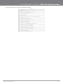
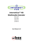
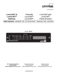
1.3 LED Indicators
The front panel LED indicators are shown in this illustration and followed by detailed explanations in the table below.
LED
COLOR MODE
P OWER
Blue
On
Off
Power off
P hone
Blue
On
Phone line active
LA N 1~2
W iFi
Inter net
3G
2G
Low
Med
High
NOTE:
Blue
Blue
Blue
Blue
Blue
Blue
Blue
Blue
DESCRIPTION
Power on
Off
Phone line inactive or not connected
Flashing
N ew Voice mail
On
Powered device connected to the
associated port (includes devices with
wake-on- LAN capability where a slight
voltage is supplied to an Ether net
connection)
Off
N o activity, modem powered off, no
cable or no powered device connected
to the associated port
Blink
LAN activity present (traffic in either
direction)
On
The wireless module is ready.
Off
The wireless module is not installed.
Blink
Data being transmitted or received
over W iFi.
Blink
Data is transmitted through Inter net
connection
Off
N o connection to the inter net or router
powered off
On
Inter net connection established
On
Inter net connection established.
Blink
C onnecting with UMTS cellular station
Off
N o connection with UMTS cellular
station, no activity or router powered
off.
On
Inter net connection established.
Blink
C onnecting to an EDGE, GPRS or GSM
cellular station
Off
N o connection with EDGE, GPRS or
GSM cellular station, no activity or
router powered off.
On
Low signal strength
Off
N o activity, router powered off or on
other signal strength
On
Medium signal strength
Off
N o activity, router powered off or on
other signal strength
On
H igh signal strength
Off
N o activity, router powered off or on
other signal strength
The six LEDs on the right side of the front panel display (Internet, 3G, 2G, Low, Med, High) will cycle on and off if PIN code protection is activated. In this case, you
should consult section 4.2.1 PIN Code Protection for further instructions.
HSPA WiFi Router with Voice-User Guide
6
YML10WVR
www.netcommlimited.com
NETCOMM LIBERTY SERIES - HSPA WiFi Router with Voice
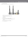
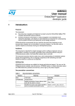
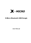
1.4 Rear Panel
The rear panel contains the ports for data and power connections.
Main 3G Antenna (removable, SMA connection)
Power jack for DC power input (12VDC / 1.5A)
Power button
USIM card slot
Aux 3G Antenna (removable, SMA connection)
USB Port (For connecting a USB Printer or USB Storage Device)
Reset button
Phone Port (for Circuit-Switched Voice Call)
2 RJ-45 Ethernet Ports
YML10WVR
www.netcommlimited.com
HSPA WiFi Router with Voice-User Guide
7
NETCOMM LIBERTY SERIES - HSPA WiFi Router with Voice
Quick Setup
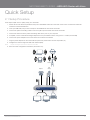
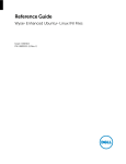
2.1 Setup Procedure
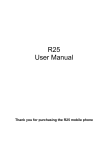
These steps explain how to quickly setup your 3G Router:
1. Attach the two 3G antennas provided to the ports marked Main and AUX on the back of the router. The antennas should be
screwed in a clockwise direction.
2. Insert your SIM card (until you hear a click) into the USIM slot at the back of the Router.
3. Connect the yellow networking cable to one of the yellow ports found at the back of the Router.
4. Connect the other end of the yellow networking cable to the port on your computer.
5. If required, connect a standard Analogue Telephone to the port labeled “Phone” using an RJ-11 Cable (not included)
6. Connect the power adapter to the Power socket on the back of the Router.
7. Plug the power adapter into the wall socket and press the power button into the ON position (in).
8. $%
;|
"
X;|"Z
NOTE:
Chapters 3 through 8 explain how to setup and use the WUI
9. )
%
X(&Z
Laptop
Smart Phone
Telephone
3G Tower
USB
Storage
Printer
Computer
YML10WVR
www.netcommlimited.com
Computer
HSPA WiFi Router with Voice-User Guide
9
NETCOMM LIBERTY SERIES - HSPA WiFi Router with Voice
Web User Interface
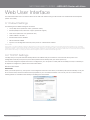
This section describes how to access the device via the web user interface using a web browser such as Microsoft Internet Explorer
(version 6.0 or later).
3.1 Default Settings
The following are the default settings for the device.
Local (LAN) access (username: admin, password: admin)
Remote (WAN) access (username: support, password: support)
User access (username: user, password: user)
LAN IP address: 192.168.1.1
Remote WAN access: disabled
#]%
}
Q$%
!
XQ$!Z
]#
}
Technical Note:
"
%
%
%
%
%
%
%
_
_=
$%
=
)
3.2 TCP/IP Settings
It is likely that your computer will automatically obtain an IP Address and join the network. This is because the Dynamic Host
$%
!
XQ$!Z
XZ
=
Q$!%
"_
%
Windows XP/Vista/7
DHCP Mode
;
=
Q$%
!
Q$!
XZ
PC for DHCP mode, check the Internet Protocol properties of your Local Area Connection. You can set your PC to DHCP mode by
selecting Obtain an IP address automatically in the dialog box shown below.
YML10WVR
www.netcommlimited.com
HSPA WiFi Router with Voice-User Guide
11
STATIC IP Mode
%
=
!$"!
=
%
!$"!
88(J8
;!
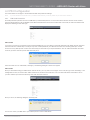
1. From the Network Connections window, open Local Area Connection (You may also access this screen by double-clicking the
Local Area Connection icon on your taskbar). Click the Properties button.
2. Select Internet Protocol (TCP/IP) and click the Properties button. The screen should now display as below. Change the IP
address to the domain of 192.168.1.x (1<x<254) with subnet mask of 255.255.255.0. Set the default router and DNS server to
"!
#}
"!
88(J88XZ!$
"!"!$"!
88(J8
3. Click OK to submit the settings.
HSPA WiFi Router with Voice-User Guide
12
YML10WVR
www.netcommlimited.com
NETCOMM LIBERTY SERIES - HSPA WiFi Router with Voice
MAC OSX 10.4
DHCP Mode
To set your Apple Mac for DHCP mode, browse to the Apple menu and select System Preferences. In the System Preferences menu,
_#
_
#|Q$!
$%
]
_]
*"!]
+
STATIC Mode
""!]
%
=
"!
=
%
"!
192.168.1.x
1. Browse to the Apple menu and select System Preferences. From the System Preferences, click the Network icon and select the
Ethernet connection.
2.
$%
)"!*
3. Choose an IP address between 192.168.1.2 – 192.168.1.254 (Do not choose the Router IP of 192.168.1.1). Enter this IP
%
_"!]
)*_&&&&&&:
4. )=
#)
%88(J88X=
"!
Z
#}
"!
88(J88XZ
"!
"!$"!
as
192.168.1.2
5. Click Apply to submit the settings.
YML10WVR
www.netcommlimited.com
HSPA WiFi Router with Voice-User Guide
13
3.3 Login Procedure
To login to the web interface, follow the steps below:
NOTE:
The default settings can be found in 3.1 Default Settings.
1.
"!
=
;
%"}^^88(J88
NOTE:
For local administration (i.e. LAN access), the PC running the browser must be attached to the Ethernet, and not necessarily to the device. For remote access, use
the WAN IP address shown on the WUI Homepage screen and login with remote username and password.
2. ]
%'8
Default Settings.
Click OK to continue.
NOTE:
The login password can be changed later (see 6.4.3 Passwords)
3. ]
%
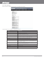
3.4 Web User Interface Homepage
The web user interface (WUI) is divided into two window panels, the main menu (on the top) and the display screen (on the bottom). The
main menu has the following options: Basic, 3G Settings, Wireless, Management, Advanced, and Status.
Selecting one of these options will open a submenu with more options. Basic is discussed below while subsequent chapters introduce
the other main menu selections.
#}
%
X
Z
BASIC / HOME
^Q
;|"%
"
%
'+"!%
The following table provides further details
FIELDS
DESCRIPTION
Software version
The software version of the device.
Ha rdware version
The Hardware version of the device
B ootloader version
The bootloader version of the device.
W ire less driver version
The wireless driver version of the wireless module.
Ne twork
The name of or other reference to the mobile network operator.
Link
S hows the connection status of the current 3G connection.
Mode
The radio access technique currently used to enable inter net access. It can be
HS UPA , H SDPA, UMTS, EDGE, GPRS or Disconnected.
Signal strength
The mobile network (UMTS or GSM) signal quality available at the device
location. This signal quality affects the performance of the unit. If two or more
bars are g reen, the connection is usually acceptable.
SIM info
S hows the SIM card status on the device.
LAN IP A ddress
S hows the IP address for LAN interface.
WAN IP A ddress
S hows the IP address for WAN interface.
De fa ult Gateway
S hows the IP address of the default gateway for the WAN interface.
Pr imary DNS S erver
S hows the IP address of the primary DN S server.
Se c o ndary DNS S erver
S hows the IP address of the secondary DN S server.
Da te /T ime
_
O nline Help
Click this Icon for Online User Guide
HSPA WiFi Router with Voice-User Guide
14
YML10WVR
www.netcommlimited.com
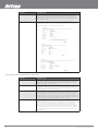
3G Settings
4.1 3G Service Setup
)
'+
%
%)
your assistance.
4.1.1
3G Settings
'+
)!"#$%
NOTE:
Sections 8.3 and 8.4.2 also provide information about the 3G service.
)
!
%
%
username and password. Only complete those steps for which you have information and skip the others.
1. If your SIM card is not inserted into the Router, then do so now.
2. ]!#]!#%]*
"
]|
"
%
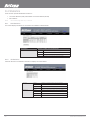
3. Select IP compression and Data compression to be ON or Off. By default they are set to off.
4. Click the Save button to save the new settings.
5. Press the Connect button to reboot the router and to connect to Internet. After reboot, the Device Info for
3G network box in the WUI Basic screen should indicate an active connection, as shown below. The 3G and
Internet LEDs on the front panel of the Router should also be blinking.
"
%
)"*
_
_"
either case, contact Technical Support for further instructions.
NOTE:
If the LEDs light in an on/off pattern moving from left to right this indicates that your SIM is PIN Locked, please lee PIN Lock Off on page 21 for instruction on how
%
HSPA WiFi Router with Voice-User Guide
16
YML10WVR
www.netcommlimited.com
NETCOMM LIBERTY SERIES - HSPA WiFi Router with Voice
!"#$%
This screen allows for changes to the 3G SIM card PIN code protection settings.
NOTE:
If you have entered the incorrect PIN 3 times, your SIM card will be locked for your security. Please call your 3G Provider for assistance.
4.2.1
PIN Code Protection
PIN code protection prevents the use of a SIM card by unauthorized persons. To use the 3G internet service with this router however,
the PIN code protection must be disabled. If the SIM card inserted into the Router is locked with a PIN code, the web user interface will
display the following screen after login.
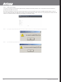
PIN Lock Off
""
!"#_)"*
%
!"#
)!"#_
!"#$!_'
)"*
_
shows how many attempts left. Contact Your 3G Carrieryour 3G Carrier if you require assistance. You can select Remember PIN Code
#!"#
when the router turns on. Afterwards, click Apply. The following dialog box should now appear.
PIN Lock On
]
%
)"*
"
_"%
'+)!"#
$%
)!"#_#
!"#=
!"#
!"#
After you do so, the following dialog box should appear.
You can now return your SIM card to your cellular phone or other mobile device.
YML10WVR
www.netcommlimited.com
HSPA WiFi Router with Voice-User Guide
17
4.2.2
PIN Code Change
If you wish to change your PIN code for greater security, enable the PIN Code protection. Go to the previous section and follow the
procedure listed under PIN Lock On.
]
_)"*
!"#$$
#!"#%
'
)"*
_
$
'+
Carrier if you require assistance. Afterwards, click Apply to activate the change.
#}
"
!"#$%
!"#_
NOTE:
If your PIN Code change request was successful the following dialog box will display.
HSPA WiFi Router with Voice-User Guide
18
YML10WVR
www.netcommlimited.com
Wireless
;
;
]
#
_X]#Z%
}
Wireless network name
Channel restrictions (based on country)
Security
Access point or bridging behaviour
Station information
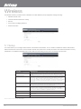
5.1 Setup
%
]#
]#
hide the network from active scans, set the wireless network name (also known as SSID) and restrict the channel set based on country
requirements. The Wireless Guest Network function adds extra networking security when connecting to remote hosts.
OPTION
DESCRIPTION
E nable W ireless
A checkbox that enables (default) or disables the wireless LAN interface. When
selected, the Web UI displays H ide Access point, SSID, BSSID and C ountry
settings.
Hide A ccess P oint
S elect Hide Access Point to protect the access point from detection by wireless
active scans. To check AP status in W indows XP, open N etwork C onnections
from the start Menu and select V iew Available N etwork C onnections. If the
access point is hidden, it will not be listed there. To connect a client to a hidden
access point, the station must add the access point manually to its wireless
configuration.
SS ID [1-32 characters]
S ets the wireless network name. SSID stands for Service Set Identifier. All
stations must be configured with the correct SSID to access the WLAN . If the
S S ID does not match, that user will not be granted access.
B S S ID
The BS S ID is a 48bit identity used to identify a particular BSS (Basic Service
S et) within an area. In Infrastructure BSS networks, the BSSID is the MAC
(Media A ccess C ontrol) address of the AP (Access Point) and in Independent
BS S or ad hoc networks, the BSSID is generated randomly.
Co untry
A drop-down menu that permits worldwide and specific national settings.
W ireless Guest
The Guest SSID (V irtual Access Point) can be enabled by selecting the Enable
W ireless Guest
Network checkbox
Rename the W ireless Guest N etwork as you wish.
NOTE: wireless hosts cannot scan Guest SSIDs.
HSPA WiFi Router with Voice-User Guide
20
YML10WVR
www.netcommlimited.com
NETCOMM LIBERTY SERIES - HSPA WiFi Router with Voice
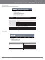
5.2 Security
This Router includes a number of security options that provides you with a secure connection to a 3G network. State-of-the art
security includes:
WEP / WPA / WPA2 data encryption
SPI Firewall
VPN Pass-Through
*]$
"!%
Authentication protocols – PAP / CHAP
You can authenticate or encrypt your service on the WiFi Protected Access (WPA), which provides protection against unauthorized
access such as eavesdropping.
)
)
%
=
wireless LAN interface. You can set the network authentication method, select data encryption, specify whether a network key is
required to authenticate to this wireless network and specify the encryption strength.
$_)^]%
YML10WVR
www.netcommlimited.com
HSPA WiFi Router with Voice-User Guide
21
OPTION
DESCRIPTION
Se lect S S ID
Your S ervice Set Identifier (SSID), sets your W ireless N etwork N ame. You can
connect multiple devices including Laptops, Desktop PC s and PDAs to your
W ireless Router. To get additional devices connected, scan for a network, and
locate the SSID shown on your W ireless Security C ard. If the SSID does not
match, access is denied.
Ne twork A uthentication
This option is used for authentication to the wireless network. Each
authentication type has its own settings as illustrated below. For example,
selecting 8 02.1X authentication will reveal the RADIUS Server IP address, Port
and Key fields. WEP Encryption will also be enabled.
The settings for WPA authentication are shown below.
OPTION
DESCRIPTION
WE P Encryption
This option indicates whether data sent over the network is encrypted. The same
network k ey is used for data encryption and network authentication. Whilst four
network k eys can be defined, only one can be used at any one time. Use the
network k ey found in the drop down list.
WPA
WPA (W i-Fi Protected Access) authentication is suitable for enterprise
applications. It must be used in conjunction with an authentication server such
as RA DIUS to provide centralized access control and management. It provides a
stronger encryption and authentication solution.
WPA-P S K/WPA 2-P S K
A newer type of security is WPA-PSK (TKIP) and WPA2-PSK (AES). This type
of security gives a more secure network compare to WEP. Use TKIP Encryption
Type for WPA-PSK and AES for WPA2-PSK. After that, please enter the key in
the P assphrase field. The key needs to be more than 8 characters and less than
63 characters and it can be any combination of letters and numbers. Please note
that the configuration for WPA-PSK and WPA2-PSK is identical.
E ncryption S trength
This drop-down list box will display when WEP Encryption is enabled. The key
strength is proportional to the number of binary bits comprising the key. This
means that keys with a greater number of bits have a greater degree encrypted
data. of se curity and are considerably more difficult to crack. Encryption
strength can be set to either 64-bit or 128-bit. A 64-bit key is equivalent to 5
A S CII characters or 10 hexadecimal numbers. A 128-bitkey contains 13 ASC II
characters or 26 hexadecimal numbers. FYI: Each key contains a 24-bit header
(an initiation vector) which enables parallel decoding of multiple streams of
encrypted data.
HSPA WiFi Router with Voice-User Guide
22
YML10WVR
www.netcommlimited.com
NETCOMM LIBERTY SERIES - HSPA WiFi Router with Voice
&'$%
$%
Wireless Local Area Network (WLAN) interface:
Select the channel which you wish to operate from
Force the transmission rate to a particular speed
Set the fragmentation threshold
Set the RTS threshold
Set the wake-up interval for clients in power-save mode
Set the beacon interval for the access point
Set Xpress mode
Program short or long preambles
$_)^]
%
OPTION
DESCRIPTION
AP Isola tion
S elect On or Off. By enabling this feature, wireless clients associated with the Access Point can be linked.
Band
The new amendment allows IEEE 802.11g units to fall back to speeds of 11 Mbps, so IEEE 802.11b and IEEE
802.11g devices can coexist in the same network. The two standards apply to the 2.4 GH z frequency band. IEEE
802.11g creates data-rate parity at 2.4 GH z with the IEEE 802.11a standard, which has a 54 Mbps rate at 5 GHz.
(IEEE 802.11a has other differences compared to IEEE 802.11b or g, such as offering more channels.)
Cha nne l
A llows selection of a specific channel (1-14) or Auto mode.
Auto Cha nne l T ime r ( min)
The A uto Channel times the length it takes to scan in minutes.
54g R a te
In A uto (default) mode, your Router uses the maximum data rate and lowers the data rate dependent on the signal
strength. The appropriate setting is dependent on signal strength. Other rates are discrete values between 1 to 54
Mbps.
M ultic a st R a te
S etting for multicast pack et transmission rate. (1-54 Mbps)
Basic R a te
S ets basic transmission rate.
Fragme nta tion Thre shold
A threshold (in bytes) determines whether packets will be fragmented and at what size. Packets that exceed the
fragmentation threshold of an 802.11 WLAN will be split into smaller units suitable for the circuit size. Packets
smaller than the specified fragmentation threshold value however are not fragmented. Values between 256 and 2346
can be entered but should remain at a default setting of 2346. Setting the Fragmentation Threshold too low may
result in poor performance.
R TS Thre shold
Request To S end (R TS ) specifies the packet size that exceeds the specified R TS threshold, which then trigg ers the
R TS /CTS mechanism. S ma ller packets are sent without using R TS/C TS. The default setting of 2347 (max length) will
disables the R TS Threshold.
D TIM Inte r va l
Delivery Traffic Indication Message (DTIM) is also known as Beacon Rate. The entry range is a value between 1
and 65535. A DTIM is a countdown variable that informs clients of the next window for listening to broadcast and
multicast messages. When the AP has buffered broadcast or multicast messages for associated clients, it sends
the next DTIM with a DTIM Interval value. AP C lients hear the beacons and awaken to receive the broadcast and
multicast messages. The default is 1.
Bea c on Inte r va l
The amount of time between beacon transmissions in is milliseconds. The default is 100 ms and the acceptable
range is 1 – 65535. The beacon transmissions identify the presence of an access point. By default, network devices
passively scan all RF channels listening for beacons coming from access points. Before a station enters power save
mode, the station needs the beacon interval to know when to wake up to receive the beacon.
X p re ss™ Te c hnology
It has been designed to improve wireless network efficiency. Default is disabled.
YML10WVR
www.netcommlimited.com
HSPA WiFi Router with Voice-User Guide
23
OPTION
DESCRIPTION
54g Mode
S elect A uto mode for greatest compatibility. Select Performance mode for the fastest performance
among 54g certified equipment. Select LRS mode if you are experiencing difficulty with legacy 802. 11b
equipment. If this does not work, you may also try 802.11b only mode.
54g Prote c tion
In A uto mode, the router will use R TS/C TS to improve 802.11g performance in mixed 802.11g/802. 11b
networks. Tur ning protection Off will maximize 802.11g throughput under most conditions.
Pre a mble Type
S hort preamble is intended for applications where maximum throughput is desired but it does not work
with legacy equipment. Long preamble works with the current 1 and 2 Mbit/s DSSS specification as
described in IEEE Std 802.11-1999
Tr a nsmit Pow e r
S et the power output (by percentage) as desired.
5.4 MAC Filter
This screen appears when Media Access Control (MAC) Filter is selected. This option allows access to be restricted based upon the
unique 48-bit MAC address.
*]$]
%
_]
%
_=
OPTION
DESCRIPTION
MAC Restrict Mode
Disabled – Disables MAC filtering
A llow – Permits access for the specified MAC addresses.
}]
*]$
_]
#
=
*]$
Deny – Rejects access for the specified MAC addresses
MAC Address
Lists the MAC addresses subject to the MAC Restrict Mode. The Add button
prompts an entry field that requires you type in a MAC address in a twocharacter, 6-byte convention: xx:xx:xx:xx:xx:xx where xx are hexadecimal
numbers. A maximum of 60 MAC addresses can be added.
Enter the MAC address on the screen below and click Save/Apply.
HSPA WiFi Router with Voice-User Guide
24
YML10WVR
www.netcommlimited.com
NETCOMM LIBERTY SERIES - HSPA WiFi Router with Voice
5.5 Wireless Bridge
;
%
features of the wireless LAN interface.
$_)^]%
FEATURE
DESCRIPTION
AP Mode
S electing W ireless Bridge (W ireless Distribution System) disables Access Point (AP
functionality while selecting Access Point enables AP functionality. In Access Point mode,
wireless bridge functionality will still be available and wireless stations will be able to associate
to the A P.
B r idge Restrict
S electing Disabled in Bridge Restrict disables W ireless Bridge restriction, which means that
any wireless bridge will be granted access. Selecting Enabled or Enabled (Scan) allows
wireless bridge restriction. Only those bridges selected in Remote Bridges will be granted
access. Click Refresh to update the station list when Bridge Restrict is enabled.
5.6 Station Info
The following screen appears when you select Station Info, and shows authenticated wireless stations and their status.
Click the Refresh button to update the list of stations in the WLAN.
OPTION
DESCRIPTION
BS S ID
The BS S ID is a 48-bit identity used to identify a particular BSS (Basic Service
S et) within an area. In Infrastructure BSS networks, the BSSID is the MAC
X*] $ Z
]!X]!Z"
BS S or ad hoc networks, the BSSID is generated randomly.
A ssociated
Lists all the stations that are associated with the Access Point, along with the
amount of tim e since packets were transferred to and from each station. If a
station is idle for too long, it is removed from this list.
A uthorized
Lists those devices with authorized access.
YML10WVR
www.netcommlimited.com
HSPA WiFi Router with Voice-User Guide
25
NETCOMM LIBERTY SERIES - HSPA WiFi Router with Voice
Management
The Management menu has the following maintenance functions and processes:
6.1 Device Settings
6.2 Simple Network Management Protocol (SNMP)
6.3 Simple Network Time Protocol (SNTP)
6.4 Access Control
6.5 Save and Reboot
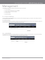
6.1 Device Settings
The Device Settings screens allow you to backup, retrieve and restore the default settings of your Router. It also provides a function for
=
%
6.1.1 Backup Settings
_$__)
%
%_%
!$
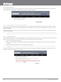
6.1.2
Update Settings
The following screen appears when selecting Update from the submenu. By clicking on the Browse button, you can locate a previously
%%
_%$_|
YML10WVR
www.netcommlimited.com
HSPA WiFi Router with Voice-User Guide
27
6.1.3 Restore Default
The following screen appears when selecting Restore Default. By clicking on the Restore Default Settings button, you can restore your
=
%
=
NOTE:
The default settings can be found in section 3.1 Default Settings.
Once you have selected the Restore Default Settings button, the following screen will appear. Close the window and wait 2 minutes
"
%
!$"!
%
X'$!^"!
Settings for details).
After a successful reboot, the browser will return to the Device Info screen. If the browser does not refresh to the default screen, close
and restart the browser.
NOTE:
The Restore Default function has the same effect as the reset button. The device board hardware and the boot loader support the reset to default button. If the
&X
8Z
%
memory.
6.1.4
Update Firmware
|
=
%
*
%
1.
%
2.
%%
%)
#%
_
%
3. $_|)
%
NOTE:
The update process will take about 2 minutes to complete. The Router will reboot and the browser window will refresh to the default screen upon successful
installation.
"
)
<
X;|"Z%
%
HSPA WiFi Router with Voice-User Guide
28
YML10WVR
www.netcommlimited.com
NETCOMM LIBERTY SERIES - HSPA WiFi Router with Voice
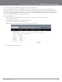
($%
)#*!'+8:;<=
The Simple Network Management Protocol (SNMP) allows a network administrator to monitor a network by retrieving settings on
remote network devices. To do this, the administrator typically runs an SNMP management station program such as MIB browser on
)#*!'+8:;<=X)#*!Z])#*!
)#*!
%]
)#*!
and managers. By default, SNMP agent is enabled on the router.
Setting up SNMP agent
1.
X"^%
^)
Z]#
X}^^88(J88Z
to log into the web interface.
2. The login username and password by default is admin/admin.
3. Go to Management> SNMP for 3G10WVR. Enable
4. SNMP agent and set up all options according to the description form below.
5. Press Save/Apply to activate setting.
YML10WVR
www.netcommlimited.com
HSPA WiFi Router with Voice-User Guide
29
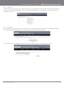
6.3 Simple Network Time Protocol (SNTP)
%
=
"
_
as illustrated below.
The following options should now appear (see screenshot below):
First NTP timeserver:
Select the required server.
Second NTP timeserver:
Select second timeserver, if required.
Time zone offset:
Select the local time zone.
$%
_)^]
NOTE:
SNTP must be activated to use Parental Control (section 7.3.2).
6.4 Access Control
]$
*
%
in the following three areas:
Services
IP Addresses
Passwords
Access Control is used to control local and remote management settings for your Router.
HSPA WiFi Router with Voice-User Guide
30
YML10WVR
www.netcommlimited.com
NETCOMM LIBERTY SERIES - HSPA WiFi Router with Voice
6.4.1
Services
The Service Control List (SCL) allows you to enable or disable your Local Area Network (LAN) or Wireless Area Network (WAN) services
by ticking the checkbox as illustrated below. These access services are available: FTP, HTTP, ICMP, SSH, TELNET, and TFTP. Click
Save/Apply to continue.
6.4.2
IP Address
The IP Address option limits local access by IP address. When the Access Control Mode is enabled, only the IP addresses listed here
can access the device. Before enabling Access Control Mode, add IP addresses with the Add button.
On this screen, enter the IP address of a local PC which you wish to allow permission. Click Save/Apply to continue.
YML10WVR
www.netcommlimited.com
HSPA WiFi Router with Voice-User Guide
31
6.4.3
Passwords
!
%
=
]
user accounts:
admin is to be used for local unrestricted access control
support is to be used for remote maintenance of the device
%
|%
!
8(
spaces. Click Save/Apply to continue.
6.5 Save and Reboot
%
=
#8}
"
%
$!^"!
%
Q$%
!
(DHCP) server you will need to apply Static IP settings.
NOTE2:
If you lose all access to your web user interface, simply press the reset button on the rear panel for 5-7 seconds to restore default settings.
HSPA WiFi Router with Voice-User Guide
32
YML10WVR
www.netcommlimited.com
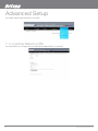
Advanced Setup
This chapter explains advanced setup for your Router:
7.1 Local Area Network (LAN)
%
]
#
_X]#Z
=
HSPA WiFi Router with Voice-User Guide
34
YML10WVR
www.netcommlimited.com
NETCOMM LIBERTY SERIES - HSPA WiFi Router with Voice
)%
OPTION
DESCRIPTION
I P Addre ss
Enter the IP address for the LAN interface
S ubne t Ma sk
Enter the subnet mask for the LAN interface
Ena ble UPnP
T ick the box to enable Universal Plug and Play
Ena ble Ha lf-B r idge
The Router can be set up as a half- transparent bridge to cope with some
special applications such as VPN pass-through.
Ena ble Inte r ne t G roup Management P rotocol (IGMP ) S nooping
Enable by ticking the box
S ta nda rd Mode :
In standard mode, multicast traffic will flood to all bridge ports when no client
subscribes to a multicast group.
Bloc king Mode :
In blocking mode, the multicast data traffic will be blocked. When there are no
client subscriptions to a multicast group, it will not flood to the bridge ports.
Dyna mic Host Config uration P rotocol (DHCP ) S erver
Select Enable DH C P server and enter your starting and ending IP addresses
and the lease time. This setting configures the router to automatically assig n IP,
default gateway and DN S server addresses to every DH C P client on your LAN
Ena ble NAT
To enable/disable N etwork Address Translation (N AT, please refer to 7.2 for NAT
setting). By default N AT is enabled.
Option 42, 66,150,16 0
These options are used for special DH C P set up.
S ta tic IP Le a se List
To specify the IP address assigned through DH C P according to the MAC address
of the hosts connected to H SPA W iFi Router.
Ena ble DHCP Se r ve r Relay
To relay DH C P requests from the subnet with no DH C P server on it to a DHCP
server on other subnets. DH C P Server Relay is disabled by default. To acc ess
enable DH C P relay, please un-tick N AT enable first, that means to disable NAT
first, and then press save button. The Enable DH C P server Relay option will then
show up on the same page as below:
Ena ble Ha lf-B r idge
the Router can be set up as a half- transparent bridge to cope with some special
applications such as VPN pass-through. By default half- bridge is off. Plea se
refer to Appendix B for more information.
Ena ble NAT
To enable/disable N etwork Address Translation (N AT, please refer to 7.2 for NAT
setting). By default N AT is enabled
Option 42, 66,150,16 0
These options are used for special DH C P set up
S ta tic IP Le a se List
To specify the IP address assigned through DH C P according to the MAC address
of the hosts connected to H SPA W iFi Router
Ena ble DHCP Se r ve r Relay
To relay DH C P requests from the subnet with no DH C P server on it to a DHCP
server on other subnets. DH C P Server Relay is disabled by default. To acc ess
enable DH C P relay, please un-tick N AT enable first, that means to disable NAT
first, and then press save button. The Enable DH C P server Relay option will then
show up on the same page as below
$%
"!
__
}
#}
I P Addre ss:
Enter the secondary IP address for the LAN interface.
S ubne t Ma sk:
Enter the secondary subnet mask for the LAN interface.
)%
)^=
%
XZ
YML10WVR
www.netcommlimited.com
HSPA WiFi Router with Voice-User Guide
35
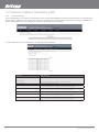
7.2 Network Address Translation (NAT)
7.2.1
Port Forwarding
!
%
"
X%!
Z
with a private IP address on the LAN side. The Internal port is required only if the external port needs to be converted to a different port
]#]'
%
To add a Virtual Server, click the Add button. The following screen will display.
OPTION
DESCRIPTION
Se le c t a S ervice
User should select the service from the list.
Or
Or
Custom Server
Create a customer server and enter a name for the server
Se r ve r IP A ddress
Enter the IP address for the server.
E xte r na l P ort S tart
Enter the starting exter nal port number (when you select C ustom Server). When
a service is selected the port ranges are automatically configured.
E xte r na l P ort End
Enter the ending exter nal port number (when you select C ustom Server). When a
service is selected the port ranges are automatically configured.
Protoc ol
User can select from: TC P, TC P/UDP or UDP.
Inte r na l Po rt S tart
Enter the inter nal port starting number (when you select C ustom Server). When a
service is selected the port ranges are automatically configured
Inte r na l Po rt End
Enter the inter nal port ending number (when you select C ustom Server). When a
service is selected the port ranges are automatically configured.
HSPA WiFi Router with Voice-User Guide
36
YML10WVR
www.netcommlimited.com
NETCOMM LIBERTY SERIES - HSPA WiFi Router with Voice
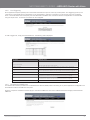
7.2.2
Port Triggering
)
%
=
%
!
!
%
]#$!^|!
!
=
;]#_]#
!
]'
%
To add a Trigger Port, simply click the Add button. The following will be displayed.
7.2.3
OPTION
DESCRIPTION
Se le c t a n Application
User should select the application from the list.
Or
Or
Custom Application
User can enter the name of their choice.
Tr igge r Por t Start
Enter the starting trigger port number (when you select custom application).
When an application is selected, the port ranges are automatically configured.
Tr igge r Por t End
Enter the ending trigger port number (when you select custom application).
When an application is selected, the port ranges are automatically configured.
Tr igge r Protocol
T C P, TC P/UDP or UDP.
O pe n Por t Start
Enter the starting open port number (when you select custom application). When
an application is selected, the port ranges are automatically configured.
O pe n Por t E nd
Enter the ending open port number (when you select custom application). When
an application is selected, the port ranges are automatically configured.
O pe n Protoc ol
TC P, TC P/UDP or UDP
Demilitarized (DMZ) Host
=
"!_
;
]
#
_X;]#Z%
Virtual Servers table to the DMZ host computer.
"!
_]*$
"!
%_]
DMZ host.
YML10WVR
www.netcommlimited.com
HSPA WiFi Router with Voice-User Guide
37
7.3 Security
Your Router can be secured with IP Filtering or Parental Control functions.
7.3.1
IP Filtering
"!
%
"!
%*%
]%"!_%
Outgoing IP Filter
%]$$!|
"!_%
BLOCKED.
%
_]
FILTER NAME
THE FILTER RULE LABEL
Protocol
TC P, TC P/UDP, UDP or IC MP Source IP address
Source IP address
Enter source IP address Source Subnet Mask
De stination IP address
Enter source subnet mask
Source P ort (port or port:port)
Enter source port number or port range
De stination IP address
Enter destination IP address
De stination S ubnet Mask
Enter destination subnet mask
De stination port (port or port:port)
Enter destination port number or range
Incoming IP Filter
"
%$|
"!_%
be ACCEPTED.
HSPA WiFi Router with Voice-User Guide
38
YML10WVR
www.netcommlimited.com
NETCOMM LIBERTY SERIES - HSPA WiFi Router with Voice
%
_]
!
"!
%
$_)^]%
7.3.2
Parental Control
This Parental Control allows you to restrict access from a Local Area Network (LAN) to an outside network through the Router on
selected days at certain times. Make sure to activate the Internet Time server synchronization as described in section 6.3 SNTP, so that
the scheduled times match your local time.
Click Add to display the following screen.
See instructions below and click Save/Apply to apply the settings.
OPTION
DESCRIPTION
User Name
A user-defined label for this restriction
*] $] MAC address of the PC running the browser
Other MA C A ddress
MAC address of another LAN device
Days of the Week
The days the restrictions apply.
S tart Blocking T ime
The time the restrictions start
End Blocking T ime
The time the restrictions end.
YML10WVR
www.netcommlimited.com
HSPA WiFi Router with Voice-User Guide
39
7.4 Routing
Default Gateway, Static Route and Dynamic Route settings can be found in the Routing link as illustrated below.
7.4.1
Default Gateway
If the Enable Automatic Assigned Default Gateway checkbox is selected, this device will accept a default Gateway assignment. If the
_%
^
;]#
_
Save/Apply.
NOTE:
After enabling the Automatic Assigned Default Gateway, you must re-boot the Router to activate the assigned default Gateway.
7.4.2
Static Route
)=
%
$_]
=
Click the Add button to display the following screen.
Enter Destination Network Address, Subnet Mask, Gateway IP Address and/or WAN Interface. Then click Save/Apply to add the entry to
the routing table.
HSPA WiFi Router with Voice-User Guide
40
YML10WVR
www.netcommlimited.com
NETCOMM LIBERTY SERIES - HSPA WiFi Router with Voice
7.4.3
Dynamic Route
To activate this option, select the Enabled radio button for Global RIP Mode.
%
="!
__
$_)^]%
7.5 Domain Name Servers (DNS)
"]]#)_%
#)
;
]
#
_X;]#Z
"_%
primary and optional secondary DNS server IP addresses. Click on Save to apply.
#}
$_)%
_%
=
7.5.2
Dynamic DNS
The Dynamic DNS service allows a dynamic IP address to be aliased to a static hostname in any of a selection of domains, allowing the
router to be more easily accessed from various locations on the internet.
Note:
The Add/Remove buttons will be displayed only if the router has been assigned an IP address from the remote server.
To add a dynamic DNS service, click the Add button and this screen will display.
OPTION
DESCRIPTION
D-DNS provider
Select a dynamic DNS provider from the list.
Hostname
Enter the name for the dynamic DNS server.
Interface
Select the interface from the list.
Username
Enter the username for the dynamic DNS server.
Password
Enter the password for the dynamic DNS server.
YML10WVR
www.netcommlimited.com
HSPA WiFi Router with Voice-User Guide
41
NETCOMM LIBERTY SERIES - HSPA WiFi Router with Voice
Voice
The 3G10WVR Router with Voice allows you to make telephone calls over the 3G Mobile/Cellular Telephone network using a standard
Analogue Telephone via the built in RJ-11 Phone port.
Please refer to the documentation provided by the manufacturer for operating your Analogue Telephone.
#}
)"*
*
<$!
#
_!
%
Note:
That any telephone calls placed using the 3G10WVR may incur call usage charges determined by your Network Provider. Please consult with your Network
!
%
!"#$!$%
'+8:;<=
%
_)8_)
make and receive telephone calls after connecting your Analogue Telephone to the socket labeled Voice on the back of your Router.
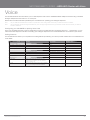
Calling Features
The 3G10WVR router allows you to experience the calling features provided by your service provider. Please refer to the table below for
more details.
CALLING FEATURE
USAGE
ACT CODE
A c c e ss Voic e Ma il
A ccess Voice Mail S tandard wireless
*98
C a ll Displa y - B loc king per call
DE-ACT CODE
#31#
C a ll For w a rding All Calls
*21* [Ten digit phone number]#
#21#
C a ll Wa iting
*43#
#43#
A nswering Call waiting
To switch between calls
H ook Flash” or “Flash” + “2”
A nswering Call Waiting and hanging up
H ook Flash” or “Flash” + “1
Dire c tor y Assista nc e
Dial 411
Eme r ge nc y Ca ll
Dial 911
C olle c t Ca lls
Collect calls cannot be received on your
wireless phone. However yo u can make an
outgoing collect call.
R oa ming
The Rocket Hub will functional only in C anada,
and only on the Rogers W ireless N etwork
YML10WVR
www.netcommlimited.com
H ook Flash” or “Flash” + “2”
HSPA WiFi Router with Voice-User Guide
43
NETCOMM LIBERTY SERIES - HSPA WiFi Router with Voice
Status
The Status menu has the following submenus:
Diagnostics
System Log
3G network
Statistics
Route
ARP
DHCP
PING
8.1 Diagnostics
The Diagnostics menu provides feedback on the connection status of the device. The individual tests are
listed below. If a test displays a fail status:
1. Click on the Help link
2. #_=
%
3. If the test continues to fail, follow the troubleshooting procedures in the Help screen.
OPTION
DESCRIPTION
E NE T Connection
P ass: Indicates that the Ether net interface from your computer is connected to
the LAN port of this Router.
Fail: Indicates that the Router does not detect the Ether net interface on your
comp uter.
W ire le ss connection
P ass: Indicates that the wireless card is ON .
Down : Indicates that the wireless card is OFF.
DATA AP N assigned IP A ddress
P ass: Indicates that the Router can communicate with the first entry point to the
_""!
")!+
Fail: Indicates that the Router was unable to communicate with the first
entry point on the network, and it may not have an effect on your Inter net
connectivity. If this test fails and you can access the Inter net, there is no need
to tro ubleshoot this issue.
Ping Pr imary Domain Name S erver
P ass: Indicates that the Router can communicate with the primary Domain N ame
S erver (DN S).
Fail: Indicates that the Router was unable to communicate with the primary
Domain N ame Server (DN S). It may not have an effect on your Inter net
connectivity. Therefore if this test fails but you are still able to access the
Inter net, there is no need to troubleshoot this issue.
YML10WVR
www.netcommlimited.com
HSPA WiFi Router with Voice-User Guide
45
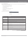
8.2 System Log
%
System Log.
1. $_$%
)
2. Select the system log options (see table below) and click Save/Apply.
OPTION
DESCRIPTION
Log
Indicates whether the system is currently recording events. You can enable or disable
event logging. By default, it is disabled.
Log le vel
A llows you to configure the event level and filter out unwanted events below this level.
The events ranging from the highest critical level “Emergency” down to this configured
=
)=]*;
full, the newest event will wrap up to the top of the log buffer and overwrite the oldest
event. By default, the log level is “Debugging”, which is the lowest critical level. The log
levels are defin ed as follows:
Emergency is the most serious event level, whereas Debugging is the least important.
For instance, if the log level is set to Debugging, all the events from the lowest
Debugging level to the most critical level Emergency level will be recorded. If the log
level is set to Error, only Error and the level above will be logged.
Displa y Level
A llows you to select the logged events and displays on the V iew System Log window for
events of this level and above to the highest Emergency level.
Mode
A llows you to specify whether events should be stored in the local memory, be sent to a
remote syslog server, or to both simultaneously.
If remote mode is selected, the view system log will not be able to display events saved
in the remote syslog server. When either Remote mode or Both mode is configured, the
WEB UI will pro mpt the you to enter the Server IP address and Server UDP port.
HSPA WiFi Router with Voice-User Guide
46
YML10WVR
www.netcommlimited.com
NETCOMM LIBERTY SERIES - HSPA WiFi Router with Voice
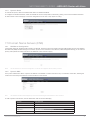
3. Click View System Log. The results are displayed as follows.
YML10WVR
www.netcommlimited.com
HSPA WiFi Router with Voice-User Guide
47
8.3 3G Status
Select this option for detailed status information on your Routers 3G connection.
$
%
STATUS
DESCRIPTION
Ma nufa c turer
The manufacturer of the embedded 3G module.
Mode l
The model name of the embedded 3G module
FW R e v
The firmware version of the 3G module.
IME I
The IMEI (Inter national Mobile Equipment Identity) is a 15 digit number that is
used to identify a mobile device on a network.
FSN
Facto ry Serial N umber of the 3G module.
IMSI
The IMSI (Inter national Mobile Subscriber Identity) is a unique 15-digit number
used to identify an individual user on a GSM or UMTS network.
HW R e v.
The hardware version of the 3G module.
Te mpe r a ture
The temperature of the 3G module in degrees C elsius.
Syste m Mode
WCD MA/Europe C DMA 2000 / America
WCDMA band
The 3 G radio frequency band which supports tri-band UTMS/H SDPA/H SUPA
frequencies (850/1900/2100 MH z), IMT2000 is 2100 MH z, WC DMA800 is 850
MHz, WC DMA1900 is 1900 MH z.
G SM ba nd
The 2 G radio frequency band which supports Quad-band GSM/GRPS
frequencies, including GSM850, GSM900, DC S1800, PC S1900 with each number
representing the respective frequency in MH z.
WCDMA channel
The 3G channel.
G SM c ha nnel
The 2 G channel.
G SM ( PS) state
P acket Switching state
MM ( CS) state
Circuit Switching state
Signa l Strength
The 3G/2G service signal strength in dBm.
HSPA WiFi Router with Voice-User Guide
48
YML10WVR
www.netcommlimited.com
NETCOMM LIBERTY SERIES - HSPA WiFi Router with Voice
OPTION
DESCRIPTION
Signa l Le vel (RS S I)
3G Radio Signal Strength Index
Q ua lity ( Ec/Io)
X^"Z
strongest cells.
Ne tw or k Registration S tatus
S hould display as registered with a valid unlocked SIM card.
Ne tw or k N ame
The 3 G inter net Service Provider.
Countr y & Network Codes
Each country and network has a unique code.
Ce ll ID
The network information for the “serving” cell ID.
Pr ima r y S crambling Code (P S C)
The PSC of the reference WC DMA cell
Da ta Se ssion S tatus
Connected or Disconnected
HSUPA/HS DPA Categories
The H SUPA/H SDPA categories correspond to different data transmission rates
with higher numbers generally indicating faster rates
R e c e ive d S ignal Code P ower (RS CP )
=)$ !
B a tte r y C onnection S tatus (BCS )
BCS of the MT (Mobile Termination)
B a tte r y C harge Level (BCL)
BCL of the MT (Mobile Termination)
YML10WVR
www.netcommlimited.com
HSPA WiFi Router with Voice-User Guide
49
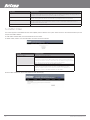
8.4 Statistics
These screens provide detailed information for:
Local Area Network (LAN) and Wireless Local Area Network (WLAN)
3G Interfaces
NOTE:
These statistics page refresh every 15 seconds.
8.4.1
LAN Statistics
This screen displays statistics for the Ethernet and Wireless LAN interfaces.
8.4.2
INTERFACE
SHOWS CONNECTION INTERFACES
Received / Transmitted
Bytes
Rx/TX (receive/transmit) packet in bytes
P k ts
Rx/TX (receive/transmit) packets
Errs
Rx/TX (receive/transmit) packets with errors
Dro ps
Rx/TX (receive/transmit) packets dropped
3G Statistics
Click 3G network in the Statistics submenu to display the screen below.
Inbound
Outbound
HSPA WiFi Router with Voice-User Guide
50
Octets
N umber of received octets over the interface.
P ack ets
N umber of received packets over the interface.
Drops
Received packets which are dropped.
Error
Received packets which are errors.
Octets
N umber of Transmitted octets over the interface.
P ack ets
N umber of Transmitted packets over the interface.
Drops
Transmitted packets which are dropped
Error
Transmitted packets which are errors.
YML10WVR
www.netcommlimited.com
NETCOMM LIBERTY SERIES - HSPA WiFi Router with Voice
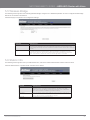
8.5 Route
Select Route to display the paths the Router has found.
DESTINATION
DESTINATION NETWORK OR DESTINATION HOST
Gateway
Next hop IP address
Subnet Mask
S ubnet Mask of Destination
Flag
U: route is up
!: reject route
G: use gateway
H: target is a host
R: reinstate ro ute for dynamic routing
D: dynamically installed by daemon or redirect
M: modified from routing daemon or redirect
Metric
XZ"
ker nels, but may be needed by routing daemons.
S ervice
S hows the name for WAN connection
Interface
S hows conne ction interfaces
8.6 ARP
Click ARP to display the ARP information.
FIELD
DESCRIPTION
IP address
Shows IP address of host pc
Flags
C omplete
Incomplete
Permanent
Publish
HW A ddress
Shows the MAC address of host pc
Device
Shows the connection interface
YML10WVR
www.netcommlimited.com
HSPA WiFi Router with Voice-User Guide
51
JKQ$%
!
XQ$!Z
Click DHCP to display the DHCP information.
FIELD
DESCRIPTION
Hostname
Shows the device/host/PC network name
MAC Address
Shows the Ether net MAC address of the device/host/PC
IP address
Shows IP address of device/host/PC
Expires In
Shows how much time is left for each DH C P Lease
8.8 PING
The PING menu provides feedback of connection test to an IP address or a host name.
Input an IP address or a host name, e.g www.google.com and press Submit. The connection test result will be shown as below.
HSPA WiFi Router with Voice-User Guide
52
YML10WVR
www.netcommlimited.com
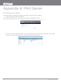
Appendix A: Print Server
For Windows Vista/7
These steps explain the procedure for enabling the Printer Server for Windows Vista or Windows 7.
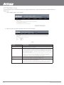
1. Enable Print Server from Web User Interface.
Select Enable on-board print server checkbox and enter Printer name and Make and model
NOTE: The Printer name can be any text string up to 40 characters. The Make and model can be any text string up to 128 characters.
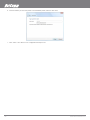
2. +
!
;<
!
;!
_]
HSPA WiFi Router with Voice-User Guide
54
YML10WVR
www.netcommlimited.com
NETCOMM LIBERTY SERIES - HSPA WiFi Router with Voice
3. )]
_
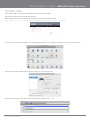
4. $_
)
}^^88(J88}('8^
^
$_#
NOTE: The PrinterName must be the same as the printer name entered into the Printer section of 3G10WVR.
5. #
_Q_
have your printer driver installation media.
YML10WVR
www.netcommlimited.com
HSPA WiFi Router with Voice-User Guide
55
6. $
_#
7. $_
%
HSPA WiFi Router with Voice-User Guide
56
YML10WVR
www.netcommlimited.com
NETCOMM LIBERTY SERIES - HSPA WiFi Router with Voice
For MAC OSX
These steps explain the procedure for enabling the Printer Server on Mac OSX.
Enable Print Server from Web User Interface.
Select Enable on-board print server checkbox and enter Printer name, Make and model
NOTE: The Printer name can be any text string up to 40 characters. The Make and model can be any text string up to 128 characters.
To set up your printer, check the Apple menu, select System Preferences. In the System Preference menu click on the Print & Fax.
With your Printer driver installed, please add your printer from the Print &Fax menu.
Mouseover to the Protocol drop down list and select Internet Printing Protocol – IPP.
YML10WVR
www.netcommlimited.com
HSPA WiFi Router with Voice-User Guide
57
"]
%88(J88}('8^
^!
#
NOTE: The PrinterName must be the same as the printer name entered into the Printer section of 3G10WVR.
From Print Using drop down list and select your corresponding printer driver.
Click Add and check the printer status.
HSPA WiFi Router with Voice-User Guide
58
YML10WVR
www.netcommlimited.com
NETCOMM LIBERTY SERIES - HSPA WiFi Router with Voice
Appendix B: Samba Server
For Windows Vista/7
Open a web-browser (such as internet Explorer, Firefox or Safari)
Type in the address \\ “NetbiosName”\ “DirectoryName” \ (eg \\ntc-cpe\ntc-cpe)
#}
|)
^
^%|)
For MAC OSX
$_%
_
Choose Connect to Server from the Go menu.
"
%$)
|=)}^^##^
#
(eg smb://ntc-cpe/ntc-cpe) )
Select Connect to connect your USB driver.
YML10WVR
www.netcommlimited.com
HSPA WiFi Router with Voice-User Guide
59
Legal & Regulatory Information
This manual is copyright. Apart from any fair dealing for the purposes of private study, research, criticism or review, as permitted under
the Copyright Act, no part may be reproduced, stored in a retrieval system or transmitted in any form, by any means, be it electronic,
mechanical, recording or otherwise, without the prior written permission of NetComm Limited. NetComm Limited accepts no liability or
responsibility, for consequences arising from the use of this product.
#$
%
NetComm is a registered trademark of NetComm Limited.
All other trademarks are acknowledged the property of their respective owners.
Customer Information
ACA (Australian Communications Authority) requires you to be aware of the following information and warnings:
(1) This unit shall be connected to the Telecommunication Network through a line cord which meets the requirements of the ACA
TS008 Standard.
(2) This equipment has been tested and found to comply with the Standards for C-Tick and or A-Tick as set by the ACA . These
standards are designed to provide reasonable protection against harmful interference in a residential installation. This equipment
generates, uses, and can radiate radio noise and, if not installed and used in accordance with the instructions detailed within this
manual, may cause interference to radio communications. However, there is no guarantee that interference will not occur with the
%"
reception, which can be determined by turning the equipment off and on, we encourage the user to try to correct the interference by
one or more of the following measures:
Change the direction or relocate the receiving antenna.
Increase the separation between this equipment and the receiver.
Connect the equipment to an alternate power outlet on a different power circuit from that to which the receiver/TV is connected.
Consult an experienced radio/TV technician for help.
(3) The power supply that is provided with this unit is only intended for use with this product. Do not use this power supply with any
other product or do not use any other power supply that is not approved for use with this product by NetComm. Failure to do so may
%
HSPA WiFi Router with Voice-User Guide
60
YML10WVR
www.netcommlimited.com
NETCOMM LIBERTY SERIES - HSPA WiFi Router with Voice
Federal Communication Commission Interference Statement
This device complies with part 15 of the FCC Rules. Operation is subject to the following two conditions: (1) This device may not
cause harmful interference, and (2) this device must accept any interference received, including interference that may cause undesired
operation.
This device has been tested and found to comply with the limits for a Class B digital device, pursuant to Part 15 of the FCC Rules.
These limits are designed to provide reasonable protection against harmful interference in a residential installation. This equipment
generates uses and can radiate radio frequency energy and, if not installed and used in accordance with the instructions, may cause
harmful interference to radio communications. However, there is no guarantee that interference will not occur in a particular installation If
this equipment does cause harmful interference to radio or television reception, which can be determined by turning the equipment off
and on, the user is encouraged to try to correct the interference by one or more of the following measures:
Reorient or relocate the receiving antenna.
Increase the separation between the equipment and receiver.
Connect the equipment into an outlet on a circuit different from that to which the receiver is connected.
Consult the dealer or an experienced radio/TV technician for help.
$
%
equipment.
The antenna(s) used for this transmitter must not be co-located or operating in conjunction with any other antenna or transmitter.
This device complies with FCC radiation exposure limits set forth for an uncontrolled environment. In order to avoid the possibility of
exceeding the FCC radio frequency exposure limits, human proximity to the antenna shall not be less than 20cm (8 inches) during
normal operation.
Operation is subject to the following two conditions: (1) this device may not cause interference, and (2) this device must accept any
interference, including interference that may cause undesired operation of the device.
IC Important Note
IC Radiation Exposure Statement:
This equipment complies with IC RSS-102 radiation exposure limits set forth for an uncontrolled environment. This equipment should be
installed and operated with minimum distance 20cm between the radiator & your body.
This device and its antenna(s) must not be co-located or operating in conjunction with any other antenna or transmitter.
The County Code Selection feature is disabled for products marketed in the US/Canada.
Operation is subject to the following two conditions: (1) this device may not cause interference, and (2) this device must accept any
interference, including interference that may cause undesired operation of the device.
This Class B digital apparatus complies with Canadian ICES-003.
Cet appareil numérique de la classe B est conforme à la norme NMB-003 du Canada.
To reduce potential radio interference to other users, the antenna type and its gain should be so chosen that the equivalent isotropically
radiated power (EIRP) is not more than that required for successful communication
This device has been designed to operate with an antenna having a maximum gain of 4 dBi. Antenna having a higher gain is strictly
prohibited per regulations of Industry Canada. The required antenna impedance is 50 ohms.
To reduce potential radio interference to other users, the antenna type and its gain should be so chosen that the equivalent isotropically
radiated power (e.i.r.p.) is not more than that permitted for successful communication.
Operation is subject to the following two conditions:
(1) this device may not cause interference, and
(2) this device must accept any interference, including interference that may cause undesired operation of the device.
YML10WVR
www.netcommlimited.com
HSPA WiFi Router with Voice-User Guide
61