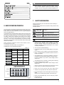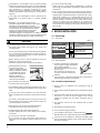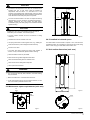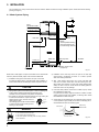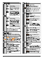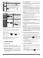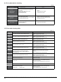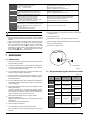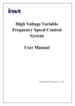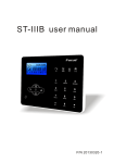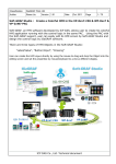
1
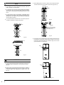
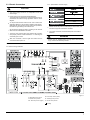
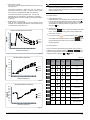
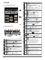
INSTALLATION & OWNER’S MANUAL
ALL IN ONE Type Air-source Heat Pump Water Heater
Thank you very much for purchasing our product,
Before using your unit , please read this manual carefully and keep it for future reference.
Your safety is the most important thing we concerned!
PARTS NAMES
Air Outlet
Air Inlet
Filter
Top Cover
Evaporator
Electronic Control Box
Fan Assy
Compressor
Junction
Box Cover
Front Cover
Display
Rear Cover
Junction Box
PTR valve
Front Decorative Board
(Optional I)
Anode Rod
Water Outlet
Cover
TCO
Cover
(Electric
Heater)
ATCO
Front Decorative Board
(Basic)
Front Decorative Board
(Optional II)
Electric Heater
Anode Rod
Water Inlet
Drain Pipe
When ordering repair parts please always give the following information:
1) Model, serial and product number.
2) Parts name.
NOTE
All the pictures in this manual are for explanation purpose only. They may be slightly different from the heat pump water heater you
purchased (depand on model). Please refer to the real sample instead of the pictures of this manual.
NOTE
Above calculation is based on the ideal condition, the final
cost bill will be different caused by the actual running
conditions, such as running period, ambient temperature, etc.
1. SAFETY INFORMATION
Please read thoroughly all of the instrucitons before installing or
operating the unit.
Following safety symbols are very important, always read and obey
all safety symbols:
0. BASIC OPERATION PRINCIPLE
As we know with our experience, the natural flow of heat, which moves
from a higher to a lower temperature source. The heat pump can
transfer heat from a lower temperature source to a higher temperature
source with high efficiency.
The advantage of a heat pump water heater is that it can supply more
heat energy, normally 3 times than input electricity power by extracting
the heat from ambient atmosphere in a free charge way to Sanitary
Hot Water, compare to the traditional water heater, such as electric
water heater or gas burner water heater, their efficiency is normally
less than 1, which means it will dramatically cut off the bill of family
daily SHW by the application of heat pump water heater, following data
will show more details.
Power consumption comparison under the same condition to heat 1
ton water from 15˚C to 55˚C
The equivalent heat load Q=CM(T1-T2)=1(kCal/kg*°C)
X1000(kg)*(55-15)(°C)=40000kCal=46.67kW*h
Table.0-1
HPW H
Gas Burner
E-heater
Energy
Resource
Air,Electricity
Gas
Electricity
Transfer Factor
860kCal/kW*h
24000kCal/m³
860kCal/kW*h
Average
Efficiency
(W/W)
3.5
0.8
0.95
Energy
Consumption
13.33kW*h
2.08m³
49.13 kW*h
Unit Cost
0.09 USD/kW*h
2.84 USD/m³
0.09 USD/kW*h
Running Cost
USD
1.2
5.9
4.42
CAUTION
You may be injured if you don't obey
instructions.
WARNING
You may be killed or seriously injured
if you don't obey instructions.
DANGER
You may be killed or seriously injured
immediately if you don't obey instructions.
WARNING
Please read the operation manual carefully and operate
according to the instruction strictly, otherwise it may cause
injury,unit damage, property loss and legal disputes. Our
company assumes no legal responsibility for any of these
caused by misoperation.
The unit must be earthed effectively.
A creepage breaker must be installed adjacent to the power
supply.
Do not remove, cover or deface any permanent instructions,
labels, or the data labels from either the outside of the unit or
inside of unit panels.
Ask qualified person to perform the installation of this unit in
accordance with local national regulations and this manual.
Improper installation may result in water leakage, electric
shock or fire.
Ask qualified person for relocating, repairing and maintaining
the unit instead of doing by yourself.
Improper installation may result in water leakage, electric
shock or fire.
Electric connection work should obey the instructions of local
power company, local electric utility and this manual.
Running Cost USD
E-heater
Never use the wire and fuse with wrong rated current,
otherwise unit may break down and cause fire furthermore.
Gas Burner
Do not insert fingers, rods or other objects into the air inlet or
outlet.
When the fan is rotating at high speed, it will cause injury.
HPWH
0
1
2
3
4
5
6
7
Fig.0-1
Never use a flammable spray such as hair spray, lacquer
paint near the unit.
It may cause a fire.
Installation & Owner's Manual
1
This appliance is not intended for use by persons (including
children) with reduced physical, sensory or mental capabilities,
or lack of experience and knowledge, unless they have been
given supervision or instruction concerning use of the
appliance by a person responsible for their safety. Children
should be supervised to ensure that they do not play with the
appliance.
If the supply cord is damaged, it must be replaced by the
manufacturer or its service agent or a similarly qualified
person.
DISPOSAL: Do not dispose this product as
unsorted municipal waste. Collection of such waste
separately for special treatment is necessary.
Do not dispose of electrical appliances as unsorted
municipal waste, use separate collection facilities.
Contact your local government for information
regarding the collection systems available.
If electrical appliances are disposed of in landfills or dumps,
hazardous substances can leak into the groundwater and get
into the food chain, damaging your health and well-being.
Do not turn off the power supply.
System will stop or restart heating automatically. A continuous
power supply for water heating is necessary, except service and
maintenance.
If the unit has not been used for a long period of time(2 weeks or
more), hydrogen gas will be produced in the water piping system.
Hydrogen gas is extremely flammable. To reduce the risk of injury
under these conditions, it is recommended that open the hot
water tap for several minutes at the kitchen sink before using any
electrical appliance connected to the hot water system. When
hydrogen is present, there will probably be an unusual sound
such as air escaping through the pipe as the water begins to flow.
There should be no smoking or open flame near the tap at the
time it is open.
2. BEFORE INSTALLATION
2.1 Unpacking
2.1.1 Accessories
Table.2-1
CAUTION
Accessory Name
The earthing pole of socket must be grounded well, make sure
that power supply socket and plug are dry enough and
connected tightly.
How to check the power supply socket and plug are qualified?
Turn on power supply and keep the unit running for a half hour,
then turn off power supply and plug out, check whether the
socket and plug is hot or not.
Before cleaning, be sure to stop the operation and turn the
breaker off or pull out the power plug.
Otherwise, an electric shock and injury may be caused.
Water temperature over 50℃
can cause severe burns
instantly or death from scalds.
Children, disabled and elderly
are at highest risk of being
scalded. Feel water before
bathing or showering.
Water temperature limiting
valves are recommanded.
Do not operate the unit with a wet hand.
An electric shock may be caused.
The installation height of power supply should be over 1.8m, if
there is any water spattered, separate the power supply from
water.
A one-way valve must be installed on the water inlet side,
which is available from accessories, see manual "accessories"
part.
It’s normal if some water drops from the hole of PTR valve
during operation. But, if there is a great amount of water, call
your service agent for instructions.
After a long term use, check the unit base and fittings.
If damaged, the unit may sink and result in injury.
Arrange the drain pipe to ensure smooth draining.
Improper drainage work may cause wetting of the building,
furniture etc.
Do not touch the inner parts of the controller.
Do not remove the front panel. Some parts inside are
dangerous to touch, otherwise a machine malfunction may be
caused.
Installation & Owner's Manual
2
Qty. Sharp
Purpose
1
Installation and use instruction
This manual
One Way Valve
1
Prevent water from
flowing backwards
Adaptor
1
Drain condensate water
2.1.2 How to transport
1) In order to avoid scratch or deformation
of the unit surface, apply guard boards
to the contacting surface.
No contact of fingers and other things
with the vanes.
Don’t incline the unit more than 15°
in moving, and keep it vertical when
installing.
Gradient limit>75°
2) This unit is heavy, it need to be carried by two or more persons,
othewise might cause injury and damage.
2.2 Location requirements
1) Enough space for installation and maintenance shall be
preserved.
2) The air inlet and outlet should be free from obstacles and strong
wind.
3) The base surface should be flat, surface should be inclined no
more than 2° and able to bear the weight of the unit and
suitable for installing the unit without increasing noise or
vibration.
4) The operation noise and air flow expelled shall not affect
neighbors.
5) No flammable gas is leaked nearby.
6) It is convenient for piping and wiring.
7) If it is installed in indoor space, it might cause indoor
decreased and noise. Please take preventive measures for this.
8) If the unit has to be installed on a metal part of building, make
sure the well electric insulation which should meet the relevant
local electric standard.
CAUTION
The ambient air temperature must also be considered when
installing this unit, in heat pump mode the ambient air
temperature must be above -7℃ and below 43℃.If the
ambient air temperature falls outside these upper and lower
limits,the electrical elements will be activated to meet the hot
water demand and the heat pump does not operate.
≥800
≥600
The unit should be located in an area not subject to freezing
temperatures. The unit located in unconditioned spaces(i.e.,
garages, basements, etc.) may require the water piping,
condensate piping, and drain piping to be insulated to shelter
agianst freezing.
CAUTION
Installing the unit in any of the following places may lead to
malfunction(If it is inevitable, consult the supplier).
The site contains mineral oils such as lubricant of cutting
machines.
Fig.2-2
2.4 If installed in inclosed space
Seaside where the air contains much salt.
Hot spring area where corrosive gases exist, e.g., sulfide gas.
Factories where the power voltage fluctuates seriously.
The water heater must be located in a space >15m³, and must have
unrestricted air flow. As an example, a room that has an 2.5 tall ceiling
and is 3 meter long by 2 meter wide would contain 15m³ .
Inside a car or cabin.
2.5 Unit outline dimension (unit: mm)
The place with direct sunlight and other heat supplies. If
there’s no way to avoid these, please install a covering.
Place like kitchen where oil permeates.
Place where strong electromagnetic waves exist.
Place where flammable gases or materials exist.
Place where acid or alkali gases evaporate.
Other special environments.
WARNING
The unit must be securely fixed, elsewise, noise and shaking
may be resulted.
Make sure that there’s no obstacle around the unit.
In the place where there is strong wind like seashore, fix the
unit in the location protected from the wind.
2.3 Maintenance space requirements (unit: mm)
Air
outlet
≥600
Fig.2-3
650
≥600
≥600
Φ650
Barrier
Air
inlet
Display
650
Fig.2-1
Fig.2-4
Installation & Owner's Manual
3
3. INSTALLATION
The circulating air for every unit should be more than 350m3/h. Make sure there is enough installation space. Outline dimensional drawing
(see Fig.2-3,Fig.2-4).
3.1 Water System Piping
User
Upper
Condensate Outlet
Lower
Condensate Outlet
Water Outlet
PTR valve
Temp. Limiting
Valve
Anode rod
Notice:
The temperature limiting
valve is required on the
hot water usage terminal.
Anode rod
Water Inlet
One Way Valve
Shut-off Valve
Drainpipe
Barrel-drain
Water inlet or outlet pipes: The spec of the water inlet or outlet thread
is RC3/4” (external thread). Pipes must be heat-insulated well.
1) Installation of the pipe for PTR valve: The spec of the valve
connecting thread is RC3/4” (internal thread). After installation, it
must be confirmed that the drainpipe outlet is exposed in the air.
CAUTION
Piping water system as the above figure. In case of installing it at
a place where outside temperature below freezing point,
insulation must be provided for all hydraulic components.
The handle of PTR valve should be pulled out once per half a year
to make sure that there is no jam of the valve.
Please beware of burn, beware of the hot
Handle
water from the valve.
Drainage
The drainage pipe should be well insulated
pipe
in order to prevent water inside pipe from
freezing in cold weather.
Tap Water
Expansion Tank for tank
(if required)
Fig.3-1
2) Installation of the One Way Valve: The spec of the One Way
Valve thread in accessories is RC3/4”. It is used to prevent
water from flowing backwards.
3) After water system piping work, turn on the cold water inlet
valve and hot water outlet valve and start effusing the tank.
When water flow smoothly out from water outlet pipe(tap water
outlet), the tank is full, turn off all valves and check pipeline to
make sure there is not any leakage.
4) If the inlet water pressure is less than 0.15MPa, a pump should
be installed at the water inlet.
For guarantee the safety usage of tank at the condition of water
supply pressure higher than 0.65MPa, a reducing valve should
be installed at the water inlet pipe.
5) Condensate may be leaked from unit if drainage pipe is blocked
or unit operates in high humidity environment, a drainage pan is
recommanded as shown as following figure:
Heat Pump
Water Heater
Max.22mm
WARNING
● Do not dismantle the PTR valve.
● Do not block off the drainage pipe.
It will cause explosion and injury, if do not comply with the
above instruction.
Installation & Owner's Manual
4
50mm larger than
the dia. of unit
Fig.3-2
3.2 Air duct connection
3) Air outlet connects to duct, air inlet without duct. (B+C≤10m)
1) Air inlet and outlet with ducts. (A+B+C+D≤10m)
Air outlet
Air outlet
A
B
B
Air inlet
Air inlet
C
C
Fig.3-5
Fig.3-3
It is recommended to install unit by this way in the winter
where there is other heat source in the room.
2) Air outlet without duct, air inlet connects to duct.(A+D≤10m)
4) Duct Description
Table.3-1
A
Air outlet
Air inlet
Duct
Round
duct
Rectangle
duct
Dimension
(mm)
Φ190
190X190
≤2
≤2
Straight-line
pressure drop
(Pa/m)
Other shaped
duct
Refer to
above data
Straight-line
length (m)
≤10
≤10
Bent pressure
drop(Pa)
≤2
≤2
Bent’s qty.
≤3
≤3
Fig.3-4
It is recommended to install unit by this way in summer
that could charge fresh air into room.
Installation
& Owner's&Manual
Installation
Owner's Manual
5
5
5) Filter installing at the unit inlet. In terms of the unit with duct, filter
in there must be put on the position of duct inlet. (Fig.3-8/3-9)
NOTE
oulet inlet
The resistance of duct will decrease air-flow-rate, which will
lead to capacity of unit decreased.
Filter
For the case of unit with duct, the duct total length should be
no more than 10m or the maximus static pressure should be
within 25Pa, and the quantity of bending should be no more
than 3.
For unit with duct, when unit operating, condensate will be
generated aroud outside of duct. Please pay attention to the
drainage work, we sugest to wrap the thermal insulated layer
around ouside of the duct.
It is recommended to install the unit in the indoor space, it is
not allow to install the unit at the rainy space.
Fig.3-8
ΦD
Rain
Filter
Owner should install the
filter by self, and the mesh
size is about 1.2mm.
Unit
Fig.3-9
Fig.3-6
Rain
6) To smoothly drain condensate from unit, please install the unit at a
horizontal floor. Otherwise, please ensure the drain vent is at the
lowest level. Recommending the inclination angle of unit to the
ground should be no more than 2°.
Weather shed
Drain
Unit
Fig.3-7
WARNING
In case of rain entering to internal components of the unit, the
component might be damaged or causing physical danger.
(Fig.3-6)
Drain
In terms of the unit connects with duct reaching to outdoor, a
reliable water-resistant measure must be conduct on the duct,
to prevent water from dropping into internal of the unit.
(Fig.3-7)
Fig.3-10
Installation & Owner's Manual
6
6
3.3.2 Specifications of Power Supply
3.3 Electric Connection
Table.3-2
CAUTION
The power supply should be an independent circuit with
rated voltage.
4
Power supply circuit should be earthed effectively.
The wiring must be performed by professional technicians in
accordance with national wiring regulations and this circuit
diagram.
An all-pole disconnection device which has at least 3mm
separation distance in all pole and a residual current device
(RCD)with the rating of above 10mA shall be incorporated in
the fixed wiring according to the national rule.
Set the electric leakage protector according to the relevant
electric technical standards of the state.
The power cord and the signal cord shall be laid out neatly
and properly without mutual interference or contacting the
connection pipe or valve.
After wire connection, check it again and make sure the
correctness before power on.
4
40/30
30 mA ≤ 0.1sec
Please choose the power cord according to above table, and
it should comply with local electric standard.
The power cord model, recommanded power cord mode is
H05RN-F.
WARNING
The unit must be installed with an Creepage Breaker near the power
supply and must be effectively earthed.
3.3.1 Electric Wiring Illustration
T5 U
T5 L
TP
T3: Evaporator Temp. Sensor
T5L: Tank Temp. Sensor (lower)
T4: Ambient Temp. Sensor
TP: Discharge Temp. Sensor
T5U: Tank Temp. Sensor (upper)
TH: Suction Temp. Sensor
Fig.3-11
Earthing
Installation & Owner's Manual
7
3.3.3 PCB I/O Ports description
Power Supply
Fan
COMP
EHEAT S.V. Crank 4-way
Heater Valve
Solar Pump
(300L)
Alarm
EEV
Transformer
Input
SW1 Factory Setting
for Disinfect
&Electric Heater
Model Selection
Solar Input
(300L)
SW2 Factory Setting
for 190L/300L Model
Selection
High Pressure
Switch
3.3.4 Switch setting
PCB has 2 bits of switches.
Table.3-4
Model selection (User never allow to alter the factory settings)
SW1
3.4 Installation checklist
3.4.1 Location
The flooring beneath the water heater must be able
_
S W1 1
SW 1
_
2
ON
OFF
Without Electric Heater
With Electric Heater
Without Disinfect
With Disinfect
Table.3-5
Model selection (User never allow to alter the factory settings)
SW2
_
S W2 1
SW 2
_
2
ON
OFF
300L model
190L model
Power furquency_60Hz
Located indoors (such as a basement or garage) and in a
vertical position. Sheltered from freezing temperatures.
Provisions made to shelter the area from water damage.
Metal drain pan installed and piped to an adequate drain.
Sufficient space to service the water heater.
Sufficient air for the heat pump to function,
the water heater must be located in a space >15m³, and must
have unrestricted air flow.
Power furquency_50Hz
NOTE
3.3.5 Electric leakage protector
L
N
For optimal efficiency and service ability, the following clearances
should be maintained: 800mm on the air inlet side, 800mm on the
air outlet side, 600mm in the back, and 600mm in the front.
Creepage Protector
GND
Power Cable
Fig.3-13
Installation & Owner's Manual
8
The unit cannot be placed into any type of closet or small
enclosure.
The site location must be free from any corrosive elements in
the atmosphere such as sulfur, fluorine, and chlorine. These
elements are found in aerosol sprays, detergents, bleaches,
cleaning solvents, air fresheners, paint, and varnish
removers, refrigerants, and many other commercial and
household products. In addition excessive dust and lint may
affect the operation of the unit and require more frequent
cleaning.
The ambient air temperature must be above -7ºC and below
43ºC.If the ambient air temperature falls outside these upper
and lower limits the electrical elements will be activated to
meet the hot water demand.
Water System Piping
4. TRIAL-RUNNING
4.1 Water affusion before operation
Before using this unit, please follow the steps below.
Water Affusion: If the unit is used for the first time or used again after
emptying the tank, please make sure that the tank is full of water
before turning on the power.
Method: see Fig.4-1
Open the cold water inlet valve and the hot
water outlet valve.
Open
Open
PTR valve(Temperature and pressure relief valve) properly
installed with a discharge pipe run to an adequate drain and
sheltered from freezing.
All piping properly installed and free of leaks.
Cold water inlet
Hot water outlet
Unit completely filled with water.
Water Affusion
Water temperature limit valve or mixer tap(recommanded)
installed per manufacturer’s instructions.
Condensate Drain Line Installation
Must be located with access to an adequate drain or
condensate pump.
Condensate drain lines installed and piped to an adequate
drain or condensate pump.
When water flows out from the water outlet,
the tank is full. Turn off the hot water outlet
valve and water affusion is finished.
Close
Hot water outlet
3.4.4 Electrical Connections
Water out
The water heater requires 230 VAC for proper operation.
Fig.4-1
Wiring size and connections comply with all local applicable
codes and the requirements of this manual.
Water heater and electrical supply are properly grounded.
CAUTION
Proper overload fuse or circuit breaker protection installed.
3.4.5 Post Installation Review
Understand how to use the User Interface Module to set the
various parameters and functions.
Understand the importance of routine inspection/maintenance
of the condensate drain pan and lines. This is to help
prevent any possible drain line blockage resulting in the
condensate drain pan overflowing.
IMPORTANT: Water coming from the plastic shroud is an
indicator that both condensation drain lines may be blocked.
Immediate action is required.
To maintain optimal operation check, remove and clean the
air filter.
Operation without water in water
tank may result in the damage of
auxiliary E-heater. Due to such
damage, manufacturer will not be
liable for any damages caused by
this issue.
After powered on, the display lights up. Users can operate
the unit through the buttons under the display.
Emptying: If the unit needs cleaning, moving etc, the tank
should be emptied.
Method: See Fig.4-2:
Close the cold water inlet valve, open the hot
water outlet valve and open drainpipe.
Open
Close
Hot water outlet
Open
Cold water inlet
Drainpipe shut-off valve
Installation & Owner's Manual
9
Running Temperature Range
Setting water temperature target range: 38~65ºC.
E-heater running ambient temperature range: -20~43ºC.
Heat pump running ambient temperature range: -7~43ºC.
Water temperature limits:
Emptying
After emptying, please replace the nut of
drainpipe.
Table.4-1
Close
Drainpipe shut-off valve
Fig.4-2
4.2 Trial- running
1)
2)
3)
4)
4)
Heat Source Shift
The default heating source is heat pump.
If ambient is range out of heat pump, heat pump will stop
running, the unit will shift automatically to activate E-heater and
show the icon LA(
) on the display, then if the ambient
temperature goes into the running range of heat pump again, it
will stop E-heater and shift automatically to heat pump again,
and the icon LA(
) will be extinguished.
5)
6)
7)
8)
1) System Structure Figure
Unit has two kinds of heat sources: heat pump(compressor)
and electric heater.
Unit will automatically select heat sources to heat water to the
target temperature.
If the target setting water temperature is higher than Max.
temp(Heat pump), the unit will activate heat pump firstly to the
Max. temperature, then stop heat pump, activate E-heater to
continually heat water to the target temperature.
If manually activate the E-heater running when heat pump
running, E-heater and heat pump will work together until the
water temperature gets to target temperature. So if want to heat
quickly, please manually activate E-heater.
Water outlet
Temperature sensor(T5U)
NOTE
Tank
E-heater will be activated once for the current heating progress,
if want to apply E-heater again, plsease push
again.
Electric heater
If only use E-heater, about only 150 liters water will be heated,
so must set higher target water temperature if ambient
temperature is out of heat pump running range.
Temperature sensor(T5L)
Water inlet
Fig.4-3
2) Water Temperature Display
The temperature shown on the display depends on the upper
sensor. So it is normal that the display temperature has
reached to target temperature but compressor still running,
because the lower water temperature does not get to target
temperature.
3) Heat source will be automatically selected by unit. But manually
E-Heater operation is available.
Installation & Owner's Manual
10
Defrosting During Water-heating
In heat pump running period, if the evaporator frosted in lower
ambient temperature, the system will defrost automatically to
keep effective performance(about 3~10min). At defrosting time,
the fan motor will stop, but compressor will still run.
COP
There is different COP in different ambient temperature. Normally
lower ambient temperature result longer heat-up time because of
lower effective performance.
When ambient temp below 7℃,heat pump and E-heater will
take different portions of heating capacity, generally the lower of
ambient temperature, the lower portion of heat pump will be taken
as well as the higher portion of E-heater will account for.
More detail please refer to Table.4-1 and Table.4-2.
About TCO and ATCO
The power of E-heater will be automatically shut-off or turn on by
TCO and ATCO.
NOTE
While the ambient temperature below than -7℃, heat pump
efficiency will decrease dramatically, the unit will automatically
shift to E-heater running.
If the water temperature is higher than 78℃, the ATCO will
automatically shut off the power of compressor and E-heater,
and reconnect it if the temperature falls down below 68℃.
If the water temperature is higher than 85℃, the TCO will
automatically shut off the power of compressor and E-heater.
After that it needs to be reset manually by pressing the red button
on the TCO.
Restart After a Long Term Stop
When the unit is restarted after a long term stop(trail running
included), it is normal that outlet water is unclean. Keep the tap
on and the water will be clean soon.
4.2.3 Basic function
1) Weekly disinfect function
Under disinfection unit immediately start to heat water up to 65℃
to kill the potential legionella bacteria inside water of tank,
icon will light on the display screen during disinfection. Unit will
quit disinfection if water temperature is higher than 65℃ and
extinguish
icon.
2) Vacation function
After pressing
button, unit will automatically heat water
to 15℃ for the purpose of energy saving during vacation days.
Heat Up Time within Different Temperature
9
3) How is the unit running
8
7
If unit is OFF->press
6
->unit will be waken->press
to set target water temperature(38-65℃)->press
5
15-45℃
4
will automatically select heat source and start to heat water to
15-55℃
3
->unit
target temperature.
15-65℃
2
4.2.4 Query function
1
0
-25
-15
-5
5
15
25
35
45
Ambient temperature(℃)
Fig.4-4
For the convenience of maintenance and debug, query function is
available by press 2 buttons together:
+
, then
system running parameters will be shown one by one with following
sequence by each pushing of
or
button.
Table.4-3
COP within Different Temperature
6.00
Temp./
Dasys
Explenation
1
Temp.
T5U
2
Temp.
T5L
3
Temp.
T3
4
Temp.
T4
5
Temp.
TP
6
Temp.
TH
7
Current
Compressor
No.
5.00
Hour
low bit
Min.
high bit
Min.
Low bit
4.00
15-45℃
3.00
15-55℃
2.00
15-65℃
1.00
0.00
-25
-15
-5
5
15
25
35
45
Ambient temperature(℃)
Fig.4-5
Capacity within Different Temperature
5000
4500
4000
3500
8
Last error code
9
Previous 1st error or
protection code
10
Previous 2nd t error or
protection code
11
Software number
3000
15-45℃
2500
2000
15-55℃
1500
15-65℃
1000
500
0
-25
-15
-5
5
15
25
35
45
Ambient temperature(℃)
Fig.4-6
Installation & Owner's Manual
11
5. OPERATION
No
⑤
⑥
Disinfect:
will be lightened when the unit is under
disinfecting, otherwise will be extinguished.
will be lightened if disinfect function is
automatically activated by unit;
will flash with 0.5 Hz frequency, if disinfect
function is manually activated;
will flash with 2Hz frequency when setting
disinfect function or setting disinfect timer.
⑦
High temp. Alarm
If setting water temp. is higher than 50℃,
will be lightened, otherwise
will be
extinguished.
⑧
Alarm:
When unit is under protection/error,
will flash
with 5Hz frequency as well as buzzer will sound
3 times every 1 minute until protection/error
eliminated or press
for 1 second.
⑨
Lock:
If button is locked,
will be lightened,
otherwise
will be extinguished.
⑩
Temperature unit
If setting temperature unit as celsius, will be
lightened,
will show celsius degree;
If setting temperature unit as Fahrenheit,
will
be lightened, will show Fahrenheit degree.
Long press button
for 10s to shift it.
SET
DAY
ON
OFF
ON
OFF
ON
OFF
ON
OFF
ON
OFF
5.2 Display Explanation
①
②
③
④
⑤
⑥
⑦
⑧
⑨
SET
DAY
ON
OFF
ON
OFF
ON
OFF
ON
OFF
ON
OFF
ON
OFF
⑩
11
11
16
15
Description
E-heater:
will be lightened if E-heater is activated,
otherwise
will be extinguished.
If E-heater is automatically activated by unit,
will be lightened;
If E-heater is manually activated,
will flash
with 0.5 Hz frequency.
When setting E-heater manually ON/OFF,
will flash with 2 Hz frequency.
5.1 Control Panel Explanation
ON
OFF
Icon
13
12
If button is under lock mode, press any button
except unlock button,
will be lightened.
Fig.5-2
:
Table.5-1
No
Icon
will be lightened if screen is unlocked.
Description
12
①
②
Wire controller:
If connected a wire controller,
will be
lightened, otherwise
be extinguished.
Outside solar heat source:
If an outside solar heat source has been
connected to the unit,
will flash with 0.5 Hz
frequency, otherwise
will be extinguished.
③
Vacation:
will be lightened if the unit is under vacation,
otherwise
will be extinguished;
will flash with 2Hz frequency when setting
vacation.
④
Compressor:
will be lightened when compressor is
running, otherwise
will be extinguished.
It shows water temperature on normal;
It shows remaining vacation days on vacation;
It shows setting temperature on setting;
It shows unit setting/running parameters,
error/protection code on querying.
Reserved
13
Setting
will be lightened when setting water
temperature or setting days for vacation.
Date setting
Installation & Owner's Manual
12
will be lightened when setting days for
vacation;
will be lightened when on vacation.
No
Icon
Description
15
Timer
There are six timers can be set.
If anyone of them has been set,
will lighten the corresponding one when
screen is unlocked;
If there is none of timers has been set,
it will keep extinguished.
If timer is being set,
corresponding one with 2Hz frequency as
well lighten the timer which has been set.
16
Clock and clock setting
shows the clock.
Whenever there is any setting for clock,
will be lightened.
①
②
③
⑨
④
⑧
⑦
⑥
⑤
Any pressing of button is effective only under button and display
unlocked state.
Table.5-2
No. Icon
Description
Manually turn E-heater ON
If E-heater is OFF, follow these steps below to
manually turn it on.
Icon
1
12
will flash.
Confirm manually turning E-heater on,
then E-heater is activated to heat up water
to the target temperature. After that, if
need manually turn E-heater on again,
please repeat these steps.
If E-heater is already ON, Press
will lead
to show invalid icon
on the display.
Long pressing the button
for 10s then can
shift to set the temperature display unit from "F" to
"C" or from "C" to "F". The default is "C"(when it's
shifted to display "F", it still will display "C" while
querying).
2
INCREASE
If screen is unlocked, corresponding value will
increase by pushing
.
● When setting temperature, press
more than
1s, Temperature value will be increased
continuously;
● When Setting clock/timer, press
more than
1s, Clock/timer value will be increased continuously;
● When setting vacation days, press
more
than 1s, day value will be increased continuously;
On querying, check items will page up by pressing
.
SET
Installation & Owner's Manual
13
SET
DAY
Installation & Owner's Manual
14
No Icon
Description
In vacation period, the setting target water
temperature is 15℃ as default and
will show
the remanent vacation days. On the last day of
vacation, unit will automatically start disinfect
function, and automatically reset the target
temperature to the last one before vacation.
If unit has already been in vacation or OFF, press
will lead to show invalid icon
on the display.
9
Icon
Clear error
code
Query
Description
Press the two buttons at
the same time to clear
all stored error & protect
codes, and the buzzer
will buzz one time.
+
Press the two buttons at
the same time for 1sec to
go into querying. On
querying user can check
unit setting & running
parameters by pressing
circularly. Press
button
for 1s or
no button operation for
30s, then quit querying.
+
5.4 Auto-restart
If electricity power failed, unit can memorize all setting parameters,
unit will be back to the previous setting when power recover.
5.5 Button Auto Lock
When there is no operation of button for 1 minute, button will be
locked except Unlock button
buttons.
, Press
Q:Why sometimes the temperature shown on the display will
decreased dramatically?
A: Because tank is pressure-bearable type, if there is massive hot
demand, hot water will quickly tapped out from upper part of tank
as well as cold water will quickly tapped into bottom part of bank if
the cold water surface emerge the upper temperature sensor,
temperature shown on the display will decreased dramatically.
Q: Why sometimes the temperature shown on the display is
decreased a lot, but there is still a mount of hot water can be
tapped?
A: Because the upper water sensor is located on the upper 1/4 tank,
when display temperature starts falling down quickly, it means
there is at least 1/4 tank of hot water available.
5.3 Combination button
No.
Q:Why sometimes the temperature shown on the display decreased
but unit still keep closed?
A: To avoid unit ON/OFF frequently, unit will activate heat source only
when bottom tank temperature is lower than setting temperature or
max. temperature for at least 5 ºC.
for 3s, unlock
5.6 Screen Auto Lock
If there is no operation of button for 30s, screen will be locked(extinguished)
except for error code and alarm icon.
Press any button will unlock the screen(lighten).
6. TROUBLE SHOOTING
6.1 Non-error tips
Q: Why compressor can't start immediately after setting?
A: Unit will wait for 3 minutes to balance the pressure of system
before starting compressor again, it's a self protection logic of unit.
Q: Why sometimes the temperature shown on the display panel
decreased while unit is running?
A: When the upper tank temperature is much higher than the bottom
part, upper part hot water will be mixed by the bottom cold water
which is continually flow from inlet tap water so that will decrease
the upper part temperature.
Q: Why sometimes unit shows "LA" on display ?
A: The heat pump available running ambient range is -7-43℃,if
ambient temperature is out of range, system will show
above-mentioned signal to let user notice it.
Q: Why something there is nothing shown on the display?
A: To maintain display screen lifespan within along term, when there
is no button operation for 30 sec, it will extinguwish the display
except the LED indicator.
Q: Why sometimes the buttons are unavailable?
A: If there is no operation on panel for 1 min, unit will lock the panel,
shows " ", to unlock the panel, please press the "ENTER" button
for 3 seconds.
Q: Why sometimes there is some water flowed from drainage pipe of
PTR valve?
A: Because the tank is pressure-bearable one, when water is heated
inside the tank, water will expand, so the pressure inside of tank
will increase, if pressure goes up more than 1.0MPa, PTR valve
will activate to relief the pressure and hot water drop will be
discharged correspondingly. If water drop is continually
discharged from PTR valve drainage pipe, it is abnormal, please
contact qualified stuff to repair.
6.2 Something about self-protection of unit
1) When the self-protection happens, the system will be stopped and
start self-check, and restart when the protection resolved.
2) When the self-protection happens, the buzzer will buzz in every
other minute, the
will flash and error code will be shown at
water temperature indicator. Press
button for 1sec to stop
buzz, but the
and error code does not disappear until
protection resolved.
3) In the following circumstance, self-protection may happen:
Air inlet or outlet is blocked;
The evaporator is covered with too much dust;
Incorrect power supply(exceeding the range of 220-240V).
6.3 When error happened
1) If some normal errors happen, unit will automatically shift to
E-heater for emergent SHW supply, please contact qualified staff
to repair.
2) If some sever errors happen, unit will not start, please contact
qualified staff to repair.
3) If some errors happen, the buzzer will buzz 3 times every other
minute and the
will flash fast. Press
for 1 sec to stop
the buzzer but the alarm icon will keep glittering.
Installation & Owner's Manual
15
6.4 Error phenomenon shooting
Table.6-1
Error
phenomenon
Cold water
tapped out and
display screen
extinguished
No hot water
tapped out
Water leakage
Possible reason
solution
Bad connection between power supply plug
and socket;
Setting water temperature too low;
Temp.sensor broken;
PCB of indicator broken.
Plug in;
Setting water temp. higher;
Contact service center.
Public water supply ceased;
Waiting for public water supply recover;
Cold water inlet pressure too low (<0.15 MPa);
Waiting for inlet water pressure increase;
Cold water inlet valve closed.
Open water inlet valve.
Hydraulic pipeline joints
are not sealed well.
Check and reseal all joints.
6.5 Error code shooting table
Table.6-2
Display
Malfunction Description
Corrective action
E0
Error of sensor T5U(upper water temperature sensor)
Maybe the connection between sensor and PCB has
released or sensor has been broken.
Contact a qualified person to service the unit.
E1
Error of sensor T5L(lower water temperature sensor)
Maybe the connection between sensor and PCB has
released or sensor has been broken.
Contact a qualified person to service the unit.
E2
Tank and Wired Controller communication error
Maybe the connection between controller and PCB has
released or PCB has been broken.
E4
Evaporator temperature sensor T3 error
Maybe the connection between sensor and PCB has
released or sensor has been broken.
Contact a qualified person to service the unit.
E5
Ambient temperature sensor T4 error
Maybe the connection between sensor and PCB has
released or sensor has been broken.
Contact a qualified person to service the unit.
E6
Compressor discharge temperature sensor TP error
Maybe the connection between sensor and PCB has
released or sensor has been broken.
Contact a qualified person to service the unit.
E8
Electric leakage error
If PCB current_induction_circuit check the current
difference between L,N >14mA, system consider it as
"electric leakage error"
Maybe some wires have been broken or bad wire
connection.
Contact a qualified person to service the unit.
E9
Compressor suction temperature sensor TH error
Maybe the connection between sensor and PCB has
released or sensor has been broken.
Contact a qualified person to service the unit.
EE
E-heater open-circuit error( IEH(Current difference
E-heater on & E-heater off )<1A)
Maybe the E-heater has been broken or bad wire
connection after repair.
EF
Clock chip error
Maybe the chip has been broken, but unit can work well
without clock-menmory, so it is needed to reset clock
when power put on again.
If necessary, contact a qualified person to service the
unit.
Ed
E-EPROM chip error
Contact a qualified person to service the unit.
P1
System high pressure protection
≥ 3.0MPa active ;≤ 2.4Mpa inactive
Installation & Owner’s Manual
16
Maybe because of system blocked, air or water or more
refrigerant in system(after repair), water temperature
sensor malfunction, ect.
Contact a qualified person to service the unit.
P2
P3
P4
LA
High discharge temperature protection
TP>110 ℃,Protection active
TP<90 ℃, Protection inactive
Compressor abnormally stopped protection
The discharge temperature is not so higher than
evaporator temperature after compressor running a
term.
Compressor overloaded protection (10 secs after
compressor startup, current checking starts ,
1)only compressor running, if it is >10A , the
compressor will be stopped and protected.)
2)Compressor+E-heater running, if it is >IEH+10,the
compressor will be stopped and protected.)
When the ambient temp T4 is out of Heat Pump
running range (-7~ 43 ℃ ) Heat Pump will stop, unit will
show LA on the position of clock on display until T4
back to (-7~ 43 ℃ ).
Only valid for the unit without E-heater.
Unit with E-heater will never show "LA".
NOTE
Maybe because of system blocked, air or water or less
refrigerant(leakage) in system( after repair), water
temperature sensor malfunction, ect.
Contact a qualified person to service the unit.
Maybe because of compressor broken or bad connection
between PCB and compressor.
Contact a qualified person to service the unit.
Maybe because of compressor broken, system blocked,
air or water or more refrigerant in system(after repair),
water temperature sensor malfunction, ect.
Contact a qualified person to service the unit.
It is normal, and no necessary to repair.
Open the drainage valve, and drain out the water, until there are
no water flow out.
The diagnostic codes listed above are the most common. If a
diagnostic code not listed above is displayed, contact residential
technical assistance referenceing the number on the front of this
manual.
Get off the anode rod.
If any of P1/P2/P3/P4 continuously appear 3 times within single
heating cycle, system will consider it as “Heat Pump system
error”. The third failure code and
will be shown on the display,
then heat pump will stop running, and the unit will shift
automatically to active E-heater as the backup heat source, but
the third failure code and
will be shown until power is reset.
Contact a qualified person to service the unit.
Open cold water inlet tap untill water flows out from outlet tap,
then turn of water outlet tap.
Replace with a new one, and make sure effective sealed.
Power on then restart the unit.
7. MAINTENANCE
7.1 Maintenance
1)
Check the connection between power supply plug and socket
and ground wiring regularly;
2)
In some cold area (below 0℃), if the system will be stopped for
a long time, all the water should be released in case of freezing
of inner tank and damage of E-heater.
3)
It is recommended to clean the inner tank and E-heater every
half year to keep an efficient performance.
4)
Check the anode rod every half year and change it, if it has
been used out. For more details, please contact the supplier or
the after-sale service.
5)
It is recommended to set a lower temperature to decrease the
heat release, prevent scale and save energy if the outlet water
volume is sufficient.
6)
Clean the air filter every month in case of any inefficiency on the
heating performance.
In terms of the filter set in air inlet directly (namely, air inlet
without connect with duct), the method of dismantle the filter is:
anti-clockwise unscrew the air inlet ring, take out the filter and
clean it completely, finally, remount it to the unit.
7)
Before shutting the system off for a long time, please:
Shut off the power supply;
Release all the water in water tank and the pipeline and close
all the valves;
Check the inner components regularly.
8) How to change the anode rod
Anode Rod
Fig.7-1
7.2 Recommended regular maintenance table
Table.7-1
Checking
Item
Checking
content
Checking frequency
Action
1
air filter
(inlet/outlet)
every month
Clean the filter
2
anode rod
every half year
Replace it if it has
been used out
3
inner tank
every half year
Clean the tank
4
E-heater
every half year
Clean E-heater
every year
Operate the
hander of PTR
valve to ensure
that waterways
are clear.
PTR valve
5
If water doesn't flow freely when operating the
hander, replace PTR valve with a new one.
Turn off the power, and turn off the water inlet valve.
Open hot water tap, and decrease the pressure of the inner
container.
Installation & Owner's Manual
17
8. SPECIFICATIONS
Table. 8-1
Model
Water-heating cap.
3000W
Rated power/AMPS
4300W/18.7A
Power supply
220-240V~ 50Hz
Operation control
Auto/Manual startup, error alarm, timer,etc
Protection
High-pressure Protector, Over-load Protector,
Temp Controller&Protector, etc
E-heater power
3000W
Refrigerant
R134a(1200g)
Outlet water temp.
Water side exchanger
Default 55°C,(38-65°C adjustable )
Safety condenser,copper tube wrapped around
outside of storage tank
Inlet pipe Dia.
DN20
Outlet pipe Dia.
DN20
Drain pipe Dia.
DN20
PTR valve Dia.
DN20
Max. pressure
1.0MPa
Material
Motor power
Air circulation way
Dimension
Water tank cap.
Net weight
Fusible link type
The test conditions:
Ambient temperature 15/12°C(DB/WB),
Water temperature from 15°C up to 45°C.
Installation & Owner's Manual
18
30CWH300
Hydrophilic aluminum fin, inner groove copper tube
80W
outlet/inlet vertically, duct connection available
Φ650×1920mm
300L
145.5kg
T30A 250VAC