1
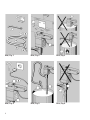
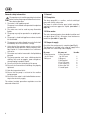
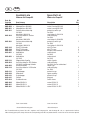
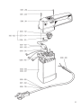
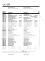
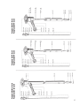
D D GB Betriebsanleitung Pumpe B2/B2-A 3–6 Operating Instructions Pump B2/B2-A 7–10 Typ/Type B2-A PP-DL 25 B2 PP-DL 25 B2 PP-DL 32 B2 Niro-DL 25 Vor Inbetriebnahme Betriebsanleitung lesen! Read this operating instructions before start up! Für künftige Verwendung aufbewahren. To be retained for future reference. D Bild / Fig. 1 Bild / Fig. 2 Bild / Fig. 3 Bild / Fig. 4 Bild / Fig. 5 Bild / Fig. 6 D Inhaltsverzeichnis 1. Allgemeines...................................................................................................... 4 1.1 Pumpwerk.................................................................................................. 4 1.2 Antriebsmotor............................................................................................ 4 1.3 Lieferumfang ............................................................................................ 4 2. Inbetriebnahme................................................................................................. 5 2.1 Aufhängevorrichtung................................................................................. 5 2.2 Eignungsprüfung....................................................................................... 5 3. Bedienung......................................................................................................... 5 3.1 Überlastung des Motors ........................................................................... 5 4. Pflege und Wartung.......................................................................................... 5 5. Reparaturen...................................................................................................... 5 EG-Konformitätserklärung ...............................................................................11 Ersatzteil-Liste Pumpe B2-Akku........................................................................12/13 Ersatzteil-Liste Motoren für Pumpe B2.............................................................14/15 Ersatzteil-Liste Pumpwerke für Pumpe B2........................................................16/17 D Allgemeine Sicherheitshinweise 1. Allgemeines Die Betriebsanleitung ist vor Inbetriebnahme vom Bediener der Pumpe zu lesen und während des Betriebs einzuhalten. 1. Der Motor ist nicht explosionsgeschützt. Die Pumpe darf nicht in explosionsgefährdeter Umgebung verwendet werden. 2. Es dürfen keine brennbaren Flüssigkeiten gefördert werden. 3. Die bestimmungsgerechte Gebrauchslage der Pumpe ist senkrecht. 4. Die Pumpe ist ein Handgerät und darf nicht ohne Aufsicht betrieben werden. 5. Die Pumpe soll nicht trockenlaufen. Bei leerem Behälter sofort abschalten. 6. Im Betrieb kann es bei niedrigem Füllstand im Behälter am Pumpenfuß spritzen. Verwenden Sie beim Einsatz von gefährlichen Flüssigkeiten Behälter mit Abdeckungen. 7. Der Motor darf nicht in die Förderflüssigkeit getaucht werden. 8. Beim Fördern gefährlicher Flüssigkeiten hat der Bediener der Pumpe passende Schutzkleidung zu tragen, Gesichtsmaske oder Schutzbrille, Schürze und Handschuhe. 9. Nicht in die Ansaugöffnung der Pumpe fassen. 10.Beachten Sie, dass alle Anschlüsse und Verbindungen richtig befestigt sind. 11.Beachten Sie die Temperaturgrenzen. 12.Prüfen Sie die Beständigkeit der Pumpe gegen das Fördermedium. 13.Prüfen Sie ob der Motor ausgeschaltet ist, bevor Sie die elektrische Verbindung herstellen. 1.1 Pumpwerk Die Unfallverhütungsvorschriften des jeweiligen Landes sind unbedingt einzuhalten. Die Fasspumpe B2 ist eine dichtungslose, vertikale Tauchkreiselpumpe mit einem axial wirkenden Rotor. Sie dient zum Um- und Abfüllen von reinen, getrübten, wasserähnlichen, aggressiven und nichtaggressiven Flüssigkeiten (siehe Tabelle 1 / Seite 6). 1.2 Antriebsmotor Die netzbetriebenen Motoren sind doppelt schutzisoliert und spritzwassergeschützt (IP 24). Alle Motoren sind funkentstört (siehe Tabelle 2 / Seite 6). 1.3 Lieferumfang Prüfen Sie die Lieferung auf Vollständigkeit (siehe Bild 1). Zum Lieferumfang der Pumpe mit 3 m Anschlusskabel und Stecker gehören: B2-Pumpe B2-Pumpen-Set Pos-Nr: 1Schlauchstecker 1Schlauchstecker für 3/4” Schlauch für 3/4” Schlauch 1Überwurfmutter1Überwurfmutter 1Aufhängevorrichtung 1,5 m PVC-Schlauch 1Lutz-Füller PP 2Schlauchschellen 3/4” 1Auslaufbogen D 2. Inbetriebnahme 2.1 Aufhängevorrichtung Befestigen Sie zunächst die Aufhängevorrichtung (B2-Pumpen-Set) an einem geschützten und doch leicht zugänglichen Platz, damit Ihre Pumpe nach jedem Gebrauch auch ordnungsgemäß aufbewahrt werden kann. Das Aufhängen der Pumpe in senkrechter Position verlängert die Lebensdauer der Pumpe und schützt das Pumpwerk vor Beschädigung und Verformung. Dabei sollte jedoch nach dem Pumpen gefährlicher Flüssigkeiten verhindert werden, dass beim Aufhängen Restflüssigkeit auf den Boden tropft (siehe Bild 2). 3. Bedienung Der Motor darf nicht in die Förderflüssigkeit getaucht werden (siehe Bild 3, oben). Mit der Pumpe dürfen keine brennbaren Flüssigkeiten gefördert werden (siehe Bild 3, unten). 3.1 Überlastung des Motors 2.2 Eignungsprüfung Der im Motor eingebaute Überstromschutzschalter schaltet bei Überlastung der Pumpe ab. In diesem Fall Motorschalter auf “0” schalten (siehe Bild 4 - Pos. 2). Nach Erkalten des Motors den Knopf des Überstromschalters betätigen (siehe Bild 4 - Pos.1) und Pumpe erneut einschalten. Prüfen Sie vor der Inbetriebnahme folgende Einsatzbedingungen: 4. Pflege und Wartung Netzspannung? Die auf dem Typenschild aufgeführte Spannung muss mit der Netzspannung übereinstimmen. Temperatur? Die Mediumstemperatur darf die Werte in Tabelle 1 (siehe Seite 6) nicht überschreiten. Viskosität und Dichte? Die Viskosität oder die spezifische Dichte der Flüssigkeit darf die Werte in Tabelle 1 (siehe Seite 6) nicht überschreiten, da sonst der Motor überlastet wird. Für den Fall eines Fördermediums mit höherer Viskosität und höherer Dichte als Wasser reduziert sich der jeweilige Maximalwert. Beständigkeit? Prüfen Sie anhand einer Beständigkeitstabelle (z.B. Lutz-Katalog), ob die Pumpe für das Fördermedium geeignet ist. Alle mit dem Fördermedium in Berührung kommenden Teile sind aus den Werkstoffen in Tabelle 1 (siehe Seite 6). Es ist erforderlich, die Pumpe nach Gebrauch in aggressiven, klebenden oder stark verschmutzten Flüssigkeiten ausreichend zu spülen (siehe Bild 5). Das Pumpengehäuse darf nicht mit Flüssigkeiten gereinigt werden, die aromatische und chlorierte Kohlenwasserstoffe enthalten (Aceton, Verdünnung). Schlauch und Schlauchanschlüsse sind regelmäßig auf Dichtheit und Beschädigung zu kontrollieren. Das Anschlusskabel ist regelmäßig auf Betriebssicherheit zu prüfen. Im Auslaufstück befindet sich eine Austrittsöffnung für Leckflüssigkeit. Tritt aus dieser Öffnung Pumpflüssigkeit aus (siehe Bild 6), ist eine Instandsetzung der Pumpe erforderlich. 5. Reparaturen Reparaturen bitte nur vom Hersteller oder autorisierten Vertragswerkstätten ausführen lassen. Nur Lutz-Ersatzteile verwenden. Beachten Sie bei der Rücksendung des Gerätes die Gebrauchs- und Dekontaminationsbescheinigung (ist in der Verpackung enthalten) und legen Sie diese ausgefüllt und unterschrieben bei. D Tabelle 1 B2-A PP-DL 25 B2 PP-DL 25 B2 PP-DL 32 B2 Niro-DL 28 650 mm 650 mm 1000 mm 1000 mm 2) 12 l/min 40 l/min 65 l/min 70 l/min Förderhöhe max. 1) 4 m WS2) 5 m WS 6,5 m WS 7 m WS Gewicht 2,0 kg 2,0 kg 2,5 kg 3,5 kg Max. Temperatur* 60 °C 60 °C 60 °C 100 °C Max. Viskosität 380 mPas 500 mPas 500 mPas 500 mPas Max. Dichte 1,3 kg/dm³ 1,3 kg/dm³ 1,3 kg/dm³ 1,3 kg/dm³ Alle mit dem Fördermedium in Berührung kommende Teile sind aus: Polypropylen Kohle HC (2.4610) PTFE Polypropylen Kohle HC (2.4610) PTFE Polypropylen Kohle HC (2.4610) PTFE Edelstahl (1.4571) Kohle PTFE ETFE Tauchtiefe Fördermenge max. 1) Gemessen mit Wasser bei 20 °C Werte sind vom Ladezustand des Akkus abhängig. * EN 60335-2-41 bis 35 °C 1) 2) Tabelle 2 Typ B2 230 V1) B2 100-120 V B2-A Spannung 230 V 100-120 V 4,8 V Frequenz 50 Hz 50-60 Hz = Leistung 200 W 150-230 W 2) Nennstrom 0,9 A 2,0 A 2) Dauerschalldruckpegel max. 70 dB(A) max. 70 dB(A) max. 63 dB(A) Vibrationsbeschleunigung < 2,5 m/s² < 2,5 m/s² < 2,5 m/s² VDE-Zulassung 2) Werte sind vom Ladezustand des Akkus abhängig. 1) GB Table of Contents 1. General................................................................................................. 8 1.1 Pump tube................................................................................... 8 1.2 Drive motor................................................................................. 8 1.3 Scope of supply . ........................................................................ 8 2. Starting up........................................................................................... 9 2.1 Wall bracket................................................................................. 9 2.2 Suitability check.......................................................................... 9 3. Operation............................................................................................. 9 3.1 Motor overload ........................................................................... 9 4. Maintenance and care.......................................................................... 9 5. Repairs................................................................................................. 9 Declaration of Conformity ...................................................................11 Spare Part List Pump B2-Accu.............................................................12/13 Spare Part List Motors for Pump B2....................................................14/15 Spare Part List Pump Tube for Pump B2.............................................16/17 GB General safety information The operator must read the operating instructions before starting the pump and follow these instructions during operation. 1. The motor is not explosion proof. The pump is not allowed to be operated in explosion hazard areas. 2. The motor must not be used to pump flammable liquids. 3. The pump may only be operated in an upright position. 4. The pump is a hand-held appliance and must not be left unattended. 5. The pump must not be allowed to run dry. Switch off immediately when the container is empty. 6. At low level of the container splash can occur at the pump foot during operation. When pumping hazardous liquids it is recommended to use containers with cover. 7. The motor must not be immersed in the liquid being pumped. 8. The pump operator must wear suitable protective clothing, face mask or goggles, apron and gloves, when pumping hazardous liquids. 9. Do not reach into the intake port of the pump. 10.Ensure that all connections and fittings are properly tightened. 11.Note the temperature limits. 12.Ensure that the pump is resistant to the medium being pumped. 13.Ensure that the motor is switched off before connecting to the electricity supply. The national accident prevention regulations must be observed without fail. 1. General 1.1 Pump tube The drum pump B2 is a sealless, vertical centrifugal pump with axially acting rotor. The pump is used to transfer pure, turbid, water-like, aggressive and non aggressive liquids (see table 1 / page 10). 1.2 Drive motor The mains-powered motors have double insulation and are splash proof (IP 24). All motors have interference protection (see table 2 / page 10). 1.3 Scope of supply Check that the consignment is complete (see Fig. 1). The following is included in the scope of supply of the pump with 3 m connecting cable and plug: B2 pump B2 pump set 1Hose connector 1Hose connector for 3/4" hose for 3/4" hose 1Wing nut1Wing nut 1Wall bracket 1.5 m PVC hose 1Lutz nozzle, PP 2Hose clips 3/4" 1Curved spout Item No. GB 2. Starting up 2.1 Wall bracket First secure the wall bracket (B2 pump set) in a sheltered, yet easily accessible place so that the pump can be stored away correctly whenever it is not in use. Storing the pump in an upright position extends its service life and protects the pump tube against damage and deformation. Care must be taken to prevent any remaining liquid from dripping onto the floor after pumping hazardous liquids (see Fig. 2). 2.2 Suitability check Check the following points before starting up the pump: Power supply? The voltage specified on the rating plate must match that provided by the mains supply. Temperature? The temperature of the medium must not exceed the values specified in table 1 (see page 10). Viscosity and density? The viscosity or the specific density of the liquid must not exceed the values listed in table 1 (see page 10), otherwise the motor will be overloaded: In case the viscosity and density of the liquid are higher than water, the respective maximum value is reduced. Resistance? Check that the pump materials are compatible with the medium being pumped (e.g. Lutz-catalogue resistance table). All parts coming into contact with the medium are made of materials as listed in table 1 (see page 10). 3. Operation The motor must not be immersed in the liquid being pumped (see Fig. 3, above). The pump must not be used to pump flammable liquids (see Fig. 3, below). 3.1 Motor overload The overcurrent release integrated into the motor switches off automatically if the pump is overloaded. The motor switch must be set to „0“ in this case (see Fig. 4 - Item 2). Allow the motor to cool, then press the red button on the overcurrent release (see Fig. 4 - Item 1) and switch the pump on again. 4. Maintenance and care The pump must be thoroughly rinsed whenever it has been used in aggressive, adhesive or highly contaminated liquids (see Fig. 5). Substances containing aromatic or chlorinated hydrocarbons (acetone, thinner) must not be used to clean the pump housing. The hose and hose connections must be inspected regularly for leaks and damage. The connecting cable must be inspected regularly to ensure safety in operation. There are leakage openings in the motor connection. The pump must be sent in for repair if any liquid emerges from these openings (see Fig. 6). 5. Repairs Repairs may only be carried out by the manufacturer or authorized repair shops. Only use genuine Lutz spare parts. When returning the device to the supplier it is compulsary to attach the decontamination certificate duly filled out and signed by the operator (see service area www. lutz-pumpen.de). GB Table 1 B2-A PP-SL 25 B2 PP-SL 25 B2 PP-SL 32 B2 SS-SL 28 Immersion depth 650 mm 650 mm 1000 mm 1000 mm Flow rate, max. 12 l/min 40 l/min 65 l/min 70 l/min Delivery head, max. 1) 4 mwc2) 5 mwc 6.5 mwc 7 mwc Weight 2.0 kg 2.0 kg 2.5 kg 3.5 kg Max. temperature* 60 °C 60 °C 60 °C 100 °C Max. viscosity 380 mPas 500 mPas 500 mPas 500 mPas Max. density 1.3 kg/dm³ 1.3 kg/dm³ 1.3 kg/dm³ 1.3 kg/dm³ All parts coming into contact with the medium are made of: Polypropylene Carbon HC (2.4610) PTFE Polypropylene Carbon HC (2.4610) PTFE Polypropylene Carbon HC (2.4610) PTFE Stainless steel (1.4571) Carbon PTFE ETFE 1) 2) Measured with water at 20 °C Values depend on the condition of the rechargeable battery. * EN 60335-2-41 up to 35 °C 1) 2) Table 2 Type B2 230 V1) B2 100-120 V B2-A Voltage 230 V 100-120 V 4.8 V Frequency 50 Hz 50-60 Hz = Power 200 W 150-230 W 2) Rated current 0.9 A 2.0 A 2) Continuous sound pressure level, max. max. 70 dB(A) max. 70 dB(A) max. 63 dB(A) Acceleration due to vibrations < 2.5 m/s² < 2.5 m/s² < 2.5 m/s² 1) 2) 10 VDE approval Values depend on the condition of the rechargeable battery. Lutz - Pumpen GmbH Erlenstraße 5-7 • D-97877 Wertheim EG-Konformitätserklärung Declaration of Conformity Hiermit erklären wir, dass die nachfolgend bezeichnete Maschine aufgrund ihrer Konzipierung und Bauart sowie in der von uns in Verkehr gebrachten Ausführung den einschlägigen grundlegenden Sicherheits- und Gesundheitsanforderungen der aufgeführten EG-Richtlinien entspricht. Bei einer nicht mit uns abgestimmten Änderung der Maschine verliert diese Erklärung ihre Gültigkeit. We herewith declare that the design and construction of the following machine in the versions marketed by us fully comply with the relevant basic safety and health requirements specified by the EC Directives listed. Geräteart: Motor zum Antrieb von Fass- und Behälterpumpen Type of device: Motor for driving drum and container pumps. Typen: B2 230 B2 100-120 B2-A Models: EG-Richtlinien: EG-Maschinenrichtlinie (98/37/EG) EG-Niederspannungsrichtlinie (73/23/EWG) (nur B2 230, B2 100-120) EG-Richtlinie über Elektromagnetische Verträglichkeit (89/336/EWG ergänzt durch 93/31/EWG) (nur B2 230, B2 100-120) Angewandte harmonisierte Normen, insbesondere EN ISO 12100-1 EN 60 335-1 (nur B2 230, B2 100-120) EN ISO 12100-2 EN 60 335-2-41 (nur B2 230, B2 100-120) EN 55 014 (nur B2 230, B2 100-120) Angewandte nationale Normen und technische Spezifikationen, insbesondere DIN 45635 This declaration ceases to be valid if the machine is modified in any way without prior consultation with us. B2 230 B2 100-120 B2-A EC Directives: EC Directive on machinery safety (98/37/EC) EC Directive of low voltage equipement (73/23/EEC) (only B2 230, B2 100-120) EC Directive on electromagnetic compatibility (89/336/EEC added by 93/31/EEC) (only B2 230, B2 100-120) Applicable harmonized standards, in particular: EN ISO 12100-1 EN 60 335-1 (only B2 230, B2 100-120) EN ISO 12100-2 EN 60 335-2-41 (only B2 230, B2 100-120) EN 55 014 (only B2 230, B2 100-120) Applicable national standards and technical specifications, in particular DIN 45635 Wertheim, 05.10.2005 Jürgen Lutz, Geschäftsführer, Managing Director 11 GB D Ersatzteil-Liste Pumpe B2-Akku PP-DL 25, 650 mm, nicht ex Spare Part List Pump B2-Accu PP-SL 25, 650 mm, not ex Best.-Nr. Order No Bezeichnung 0002-028 0002-052 + 0002-060 0102-109 0102-137 • 0102-147 • 0102-199 0102-204 0201-091 0201-183 0301-219 0301-220 0301-270 0301-277 0301-294 0303-343 0314-059 0314-101 • 0314-225 0321-147 • 0323-000 • 0332-100 0333-140 0335-125 0335-140 0335-141 0336-222 0336-223 0336-224 0343-114 0343-122 0343-154 • 0343-157 0343-241 0343-242 0343-243 0343-244 0344-006 • 0373-014 0403-519 Schalter kpl. Motorgehäuse B2-A Einbaumotor B2-A Auslaufstück PP Antriebswelle HC Führungsschlauch B2 PP W.-Rohr B2 PP DL 25 650 mm Pumpenrohr kpl. B2-A PP DL 25 bestehend aus: 0323-000 und 0343-157 Klinkenbuchse kpl. Motorgehäuse B2-Akku kpl. Polyfast-Schraube Ejot-PT-Schraube Schneidschraube Zylinderschraube Ejot-PT-Schraube Europa-Klemmleiste Flachdichtung Viton Filzring O-Ring FPM Rillenkugellager Kohlebuchse Akkupack Kabelbinder Tasterschalter f. B2 Hyd. Gleichstrommotor 7,2 V Entstörkondensator Verbindungsleitung Verbindungsleitung Verbindungsleitung Kupplungsgehäuse Schutzkappe Laufrad B 2 Einströmring Griffteil Zwischenplatte Überwurfmutter G 3/4 Schlauchstecker PP 3/4" Kupplungskreuz Schalterrahmen Silikonschlauch switch cpl. motor housing B2-A motor B2-A outrun piece PP drive shaft HC guide bushing B2 PP inner tube PP B2 PP-SL 25 650 mm outer tube B2-A cpl. consisting of: 0323-000 and 0343-157 sleeve cpl. motor housing B2-A cpl. polyfast-screw ejot-PT-screw screw screw ejot-PT-screw Europe screw terminal seal Viton felt disc o-ring FPM grooved ball bearing carbon bearing battery pack cord bandage switch f. B2 hyd. D.C.-motor 7,2 V anti interference condenser connecting wire connecting wire connecting wire coupling housing protective cap impeller B2 admission ring grip part intermediate plate wing nut G 3/4 hose connector PP 3/4" coupling cross switch frame silicon hose 1 0002-106 0102-300 Motor B2-A Pumpwerk PP-DL 25 650 mm motor B2-A pump tube PP-SL 25 650 mm 1 1 Achtung! Auslaufstück ohne eingespritzter Best.-Nr. immer mit Description Techn. Stand 01/03 • Verschleißteil/wearing part St. Qty. 1 1 1 1 1 1 1 1 4 2 4 2 2 1 1 1 2 1 1 1 1 1 1 1 1 1 1 1 1 1 1 1 1 1 1 1 1 2 gekennzeichneten Teilen austauschen. Attention: Outrun piece without molded order No. change always with market parts. State of art 01/03 + Neuteil/new part Bei Ersatzteilbestellung immer Best.-Nr. angeben und Fertigungs-Nr. oder Auftrags-Nr. des zu reparierenden Gerätes. When ordering spare-parts always indicate the corresponding order No. and production No. or order No. of the unit to be repaired. 13 D GB Ersatzteil-Liste Motoren für Pumpe B2 Best.-Nr. Order No Bezeichnung 0002-022 0002-050 + 0002-051 + 0201-021 0201-024 0201-032 0301-220 0301-294 0303-343 0333-041 • 0333-043 • 0335-123 0336-029 • 0336-050 • 0336-129 0343-122 0343-204 0343-216 0343-241 0373-014 Schalter kpl. Motorgehäuse B2 230V Motorgehäuse B2 120V Geräteschutzschalter kpl. für 230V beinhaltet: 0343-216 Anschlusskabel m. Stecker für 230V beinhaltet: 0336-050 Geräteschutzschalter kpl. für 120V beinhaltet: 0343-216 Ejot-PT-Schraube Ejot-PT-Schraube Europa-Klemmleiste Kohlebürste für 230V Kohlebürste für 120V Wippschalter 2-polig Anschlusskabel m. SEV-Stecker für 230V, Ausführung Schweiz Knickschutztülle Anschlusskabel m. US-Stecker für 120V Schutzkappe Mitnehmer Schutzkappe Griffteil Schalterrahmen 0002-030 0002-031 0002-032 Motor B2/230 V Motor B2/120 V Motor B2/230 V SEV Techn. Stand 01/03 • Verschleißteil/wearing part Motors for Pump B2 Description Spare Part List St. Qty. switch cpl. motor housing B2 230V motor housing B2 120V protective switch cpl. for 230V consisting of: 0343-216 cable with plug for 230V consisting of: 0336-050 protective switch cpl. for 120V consisting of: 0343-216 ejot-PT-screw ejot-PT-screw Europe screw terminal carbon brush for 230V carbon brush for 120V switch 2-poles cable with plug for 230V, version switzerland rubber cap cable with plug for 120V protective cap upper coupling protective cap grip part switch frame motor B2/230 V motor B2/120 V motor B2/230 V SEV State of art 01/03 1 1 1 1 1 1 2 2 1 2 2 1 1 1 1 1 1 1 1 1 1 1 1 + Neuteil/new part Bei Ersatzteilbestellung immer Best.-Nr. angeben und Fertigungs-Nr. oder Auftrags-Nr. des zu reparierenden Gerätes. When ordering spare-parts always indicate the corresponding order No. and production No. or order No. of the unit to be repaired. 15 D GB Ersatzteil-Liste Pumpwerke für Pumpe B2 Best.-Nr. Order No Bezeichnung 0102-109 0102-111 0102-137 • 0102-147 • 0102-172 • 0102-176 0102-185 0102-199 0102-203 0102-207 0102-210 • 0102-211 0102-213 • 0102-218 0300-120 0301-219 0302-005 0314-059 0314-101 • 0314-225 0321-147 • 0323-000 • 0343-001 • 0343-007 • 0343-011 • 0343-015 0343-112 • 0343-114 0343-153 • 0343-243 0343-244 0343-270 0343-271 0344-006 • Auslaufstück PP Laterne Antriebswelle PP DL 25 HC 650 mm Führungsschlauch B2 PP Führungsschlauch B2 1000 mm Schlauchstecker Niro 3/4" Dichtung PTFE W.-Rohr B2 PP-DL 25 650 mm Pumpenrohr kpl. PP-DL 25 650 mm Pumpenrohr kpl. PP-DL 32 1000 mm Antriebswelle B2 Niro-DL 28 1000 mm W.-Rohr B2 PP-DL 321000 mm Antriebswelle PP-DL 32 HC 1000 mm Pumpenrohr B2 Niro kpl. 1000 mm Gewindestift Polyfast-Schraube Flügelüberwurfmutter G 3/4 Flachdichtung Viton Filzring O-Ring FPM Rillenkugellager Kohlebuchse Lagerstern für PP-DL 32 Lagerstern kpl. ETFE für Niro-DL 28 Rotor Niro-DL 28 Steg für Niro-DL 28 Rotor PP-DL 25 Kupplungsgehäuse Rotor PP-DL 32 Überwurfmutter G 3/4 Schlauchstecker PP 3/4" Steg für PP-DL 25 Steg für PP-DL 32 Kupplungskreuz 0102-304 0102-305 0102-307 Pumpwerk PP-DL 25 650 mm Pumpwerk PP-DL 321000 mm Pumpwerk B2 Niro-DL 281000 mm Spare Part List Description St. Qty. 1 outrun piece PP connecting piece 1 drive shaft PP SL 25 HC 650 mm1 guide bushing B2 PP 1 guide bushing B2 1000 mm 1 1 hose connector SS 3/4" seal PTFE inner tube PP B2 PP-SL 25 650 mm 1 outer tube cpl. PP-SL 25 650 mm 1 outer tube cpl. PP-SL 32 1000 mm 1 drive shaft B2 SS-SL 28 1000 mm 1 inner tube B2 PP-SL 32 1000 mm 1 drive shaft PP-SL 32 HC 1000 mm 1 outer tube B2 SS cpl. 1000 mm 1 screw pin 1 4 polyfast-screw wing nut G 3/4 1 seal Viton 1 1 felt disc o-ring FPM 2 1 grooved ball bearing carbon bearing 1 bearing star for PP-SL 32 1 1 bearing star cpl. ETFE for SS-SL 28 rotor SS-SL 28 1 baffle plate for SS-SL 28 1 rotor PP-SL 25 1 coupling housing 1 rotor PP-SL 32 1 wing nut G 3/4 1 hose connector PP 3/4" 1 baffle plate for PP-SL 25 1 baffle plate for PP-SL 32 1 coupling cross 1 pump tube PP-SL 25 pump tube PP-SL 32 pump tube B2 SS-SL 28 650 mm 1000 mm 1000 mm gekennzeichneten Teilen austauschen. Attention! Outrun piece without molded order No. change always with Techn. Stand 03/03 Achtung! Auslaufstück ohne eingespritzter Best.-Nr. immer mit Pump Tube for Pump B2 market parts. State of art 03/03 1 1 1 1 Pumpwerk B2 Niro-DL 28 Pump Tube B2 SS-SL 28 17 Pumpwerk B2 PP-DL 25 Pump Tube B2 PP-SL 25 Pumpwerk B2 PP-DL 32 Pump Tube B2 PP-SL 32 GB D Best.-Nr. Order No Bezeichnung Ersatzteile für Sonderausführung Spare parts for special models 0102-108 0102-112 0343-007 • Auslaufstück PP für Typ PP-DL 32 mit Sonderabdichtung WDR / Kurzzeitbetrieb Wellendichtring Viton für Typ PP-DL 32 mit Sonderabdichtung WDR / Kurzzeitbetrieb Lagerstern kpl. ETFE für Typ PP-DL 32 mit Sonderabdichtung WDR / Kurzzeitbetrieb outrun piece PP1 for type PP-SL 32 with special sealing shaft seal / short-time duty shaft seal viton1 for type PP-SL 32 with special sealing shaft seal / short-time duty bearing star cpl. ETFE1 for type PP-SL 32 with special sealing shaft seal / short-time duty 0103-306 Pumpwerk B2 PP-DL 32 1000 mm mit Sonderdichtung WDR / Kurzzeitbetrieb pump tube B2 PP-SL 32 1000 mm1 with special sealing shaft seal / short-time duty Techn. Stand 03/03 State of art 03/03 • Verschleißteil/wearing part + Description St. Qty. + Neuteil/new part Bei Ersatzteilbestellung immer Best.-Nr. angeben und Fertigungs-Nr. oder Auftrags-Nr. des zu reparierenden Gerätes. When ordering spare-parts always indicate the corresponding order No. and production No. or order No. of the unit to be repaired. 18 Pumpwerk B2 Niro-DL 28 Pump Tube B2 SS-SL 28 19 Pumpwerk B2 PP-DL 25 Pump Tube B2 PP-SL 25 Pumpwerk B2 PP-DL 32 Pump Tube B2 PP-SL 32 D Lutz - Pumpen GmbH Erlenstraße 5-7 D-97877 Wertheim Tel. (0 93 42) 8 79-0 Fax (0 93 42) 87 94 04 e-mail: [email protected] http://www.lutz-pumpen.de Technische Änderungen vorbehalten. 01/07 Subject to technical changes. 20 Best.-Nr. 0698-000 Printed in Germany Hi. 2.000/01.08