1
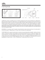
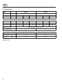
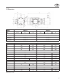
GB GB Operating Instructions horizontal, self-priming centrifugal pump Type ZMA Read this operating instructions before start up! To be retained for future reference. GB GB Table of Contents 1. Safety risks..............................................................................................................4 1.1 Installation and commissioning personnel...........................................................5 1.2 Operators and maintenance personnel................................................................5 1.3 Personnel responsible for rapairs.......................................................................5 1.4 Waste disposal..................................................................................................5 2. Improper use............................................................................................................6 3. General notes........................................................................................................6/7 4. Operating principle....................................................................................................8 5. Motor.......................................................................................................................9 6. Instructions on installation and use..........................................................................10 6.1 Transport........................................................................................................10 6.2 Installation.................................................................................................10/11 6.3 Start-up..........................................................................................................12 6.4 Use................................................................................................................12 7. Maintenance..........................................................................................................13 7.1 Dismantling.....................................................................................................13 8. Operating faults and possible causes..................................................................14/15 9. Repairs..................................................................................................................15 10. Technical data........................................................................................................16 11. Dimensions............................................................................................................17 Declaration of Conformity.............................................................................................19 GB 1. Safety risks Safety risks for personnel mainly arise from improper use or accidental damages. These risks may be of an electrical nature as far as the non-synchronous motor is concerned and may cause injury to hands if working on an open pump. Risks may also arise due to the nature of the liquids pumped. It is therefore of utmost importance to closely follow all the instructions contained in this manual so as to eliminate the causes that may lead to pump failure and the consequent leakage of liquid dangerous for both personnel and the environment. Risks may also arise from improper maintenance or dismantling practices. In any case five general rules are important: A) All services must be carried out by specialised personnel or supervised by qualified personnel depending on the type of maintenance required B) Install protection guards against eventual liquid sprays (when the pump is not installed in remote areas) due to an accidental pipe rupture. Arrange for safety basins to collect possible leakage. C) When working on the pump always wear acid-proof protective clothing. D) Arrange for proper conditions for suction and discharge valve closing during disassembly E) Make sure that the motor is completely disconnected during disassembly Proper design and building of the plants, with well positioned and well marked piping fitted with shut-off valves, adequate passages and work areas for maintenance and inspections are extremely important (should the plant be faulty constructed or present wear-and-tear defects, the pressure developed by the pump could lead to failure). It must be stressed that the major cause of pump failures leading to a consequent need to intervene is due to the pump running dry in manually operated plants. This is generally due to: - the suction valve being closed at start-up or - the suction tank being emptied without stopping GB 1.1 Installation and commissioning personnel Interventions allowed only to specialised personnel who may eventually delegate to others some operations depending on specific evaluations (technical capability required: specialisation in industrial plumbing or electric systems as needed). 1.2 Operators and maintenance personnel Interventions allowed to general operators (after training on the correct use of the plant): - pump starting and stopping - opening and closing of valves with the pump at rest - emptying and washing of the pump body via special valves and piping - cleaning of filtering elements Interventions by qualified personnel (technical capacities required: general knowledge of the mechanical, electrical and chemical features of the plant being fed by the pump and of the pump itself): - verification of environmental conditions - verification of the condition of the liquid being pumped - inspections of the control/stop devices of the pump - inspections of the rotating parts of the pump - trouble shooting 1.3 Personnel responsible for repairs Interventions allowed to general operators under the supervision of qualified personnel: - stopping of the pump - closing of the valve - emptying of pump body - disconnection of piping from fittings - removal of anchoring bolts - washing with water or suitable solvent as needed - transport (after removal of electrical connections by qualified personnel) Interventions by qualified personnel (technical capacities required: general knowledge of machining operations, awareness of possible damage to parts due to abrasion or shocks during handling, know-how of required bolt and screw tightening required on different materials such as plastics and metals, use of precision measuring instruments): - opening and closing of the pump body - removal and replacement of rotating parts 1.4 Waste disposal Materials: separate plastic from metal parts. Dispose of by authorized companies. GB 2. Improper use The pump must not be used for purposes other than the transfer of liquids. Do not use the pump with explosive liquids or with low vapour pressure. The pump cannot be used to generate isostatic or counter pressures. The pump cannot be used to mix liquids generating an exothermal reaction. The pump must be installed horizontally on a firm base. The pump must be installed on a suitable hydraulic plant with inlet and outlet connections to proper suction and discharge pipes. The plant must be able to shut off the liquid flow independently from the pump. Handling of aggressive liquids requires specific technical knowledge. 3. General notes ZMA pumps are designed and built for the transfer of liquid chemical products having a specific weight, viscosity, temperature and stability of state appropriate for use with centrifugal pumps in a fixed installation, from a tank at a lower level to a tank or a pipe to a higher level. The characteristics of the liquid (pressure, temperature, chemical reactivity, specific weight, viscosity, vapour tension) and the ambient atmosphere must be compatible with the characteristics of the pump and are defined upon ordering. Impeller and static casings, in contact with the liquid, are constructed from thermoplastic materials; other parts in high chemicalresistant materials. The max. pump’s performances (capacity, head, rpm) are defined on the identification plate. The value of the suction lift is defined upon ordering. "ZMA" pumps are self-priming, centrifugal, horizontal, single stage, close coupled to a non-synchronous electric motor, with side-inlet and upward-outlet for connection to the hydraulic system. They are foot-mounted for floor fixing. At start-up the pipes must be empty and the pump body full of liquid. The priming time depends on the suction lift and on the suction circuit (total length and diameter). "ZMA" pumps cannot run dry. The liquid being pumped may contain a maximum 1% of solid non-abrasive particles not greater than 0,1 mm in size. The presence of fibrous, adhesive or abrasive bodies is not allowed. Clockwise rotation seen from the motor side. Make sure that the chemical and physical characteristics of the liquid have been carefully evaluated for pump suitability. The specific weight which can be pumped at a temperature of 25°C (both of the liquid and the ambient) depends upon the diameter of the impeller (shown on the identification plate) and the installed motor power (shown on the motor identification plate) ans has to be defined upon ordering. The level of kinematic viscosity must not exceed 10 cSt so as not to significantly modify the pump's performance (capacity, head, suction lift, priming time). The liquid temperature is a primary factor of suction lift and has to be defined upon ordering; at 60 °C the pump is not usable as self-priming pump. GB The ambient temperature interval is related to the choice of materials (specified on the identification plate): Execution QR: 5 – +30°C Execution W and WR: 0 – +40°C Execution FC: -10 – +40 °C The maximum pressure the pump may be subjected to is 1.5 times the head value developed with the outlet closed. The vapour pressure value of the liquid to be pumped must exceed (by at least 1m w.c) to the difference between the absolute total head (suction side pressure added to the positive suction head, or subtracted by the suction lift) and the pressure drops in the suction side piping (including the inlet NPSHr drops shown on the specific tables). In case of double mechanical seal, the value of the pressure in the seal chamber must be equal to half value of the operating pressure of the pump. In case of double mechanical seal, the flushing liquid must be clean and must not lead to violent chemical reactions on contact with the liquid being pumped. The pump does not include any non return valve nor any liquid flow control or motor stop device. GB 4. Operating principle fixed seal outlet rotating mechanical inlet pumping phase stopping phase priming phase motor shaft strainer impeller pump casing HYDRAULICALLY it works in three distinct phases. During the pumping phase it works like all centrifugal pumps: equipped with a blade-type impeller rotating within a fixed housing, it has a tangential outlet and by creating a depression at the center, it allows the liquid to flow from the central suction side. Then, flowing through the impeller's blades the fluid acquires energy and is conveyed towards the outlet. During the stopping phase, while the pipes empty themselves, a certain volume of liquid remains trapped in the pump body for the subsequent pumping/priming operation. In the priming phase the impeller mixes the liquid in the pump body with the air present in the suction piping. Then this mixture enters the separation chamber where air is dispersed in the discharge pipe, and the liquid recirculates in the impeller. Once all the air has been evacuated from the suction piping (priming time), the pumping phase begins. MECHANICALLY it is extremely simple. The impeller is driven directly by the motor shaft that overhangs on the coupling side. All the mechanical loads, of a reduced nature in this type of pump, are borne by the motor bearings. THE MECHANICAL SEAL, placed at the point where the shaft enters the pump body to drive the impeller, is made up of two main sections: a fixed section inserted in the pump body and a rotating section integral with the shaft. The tight contact between these two parts guarantees a seal against leakage whether the pump is rotating or not. The rubbing action that occurs between these two parts when the pump is operating generates heat by friction; this heat is absorbed by the liquid being pumped in the case of single mechanical seal and by the cooling liquid (generally water) in the case of double seal. The presence of the thin layer of liquid between the sealing surfaces, as well as its cooling action, is indispensable for the life of the seal. GB 5. Motor Electrical connections The electrical connection to the motor terminal determines the direction of rotation of the motor and can be verified by looking at the cooling fan at the rear of the motor ( for the Argal pump this has to rotate clockwise looking at the front end). With single phase motors the direction of rotation may be reversed by changing the position of the connection plates: With three-phase motors the direction of rotation may be changed by swapping any two of the three conductors independently of the type of connection to the windings: The windings of three-phase motors ( e.g. with (a) 230-400 V; (b) 400-690 V) require a delta-connection for lower voltage ( 230 volts for a ; 400 volts for b). They require a star-connection for higher voltage (400 volts for a; 690 volts for b). Star/Delta starting is used when the motor power is above 7.5 kW (10 HP ) only in case of frequent starts and short running times, but always when the motor power is above 15kW (20 HP ). All this is also to safeguard the structure of the pump. Protection level The initials IP are followed by two numbers: The first number indicates the level of protection against penetration of solid objects and in particular : 4 for solids whose dimension is greater than 1mm 5 for dust (eventual internal deposits will not harm operation) 6 for dust (no pentetration) The second number indicates the protection against the penetration of liquids. In particular: 4 for water sprays from all directions 5 for jets of water from all directions 6 for tidal and sea waves According to the IP protection indicated on the identification plate of the motor and to the environmental conditions, arrange for opportune extra protections allowing in any case correct ventilation and rapid drainage of rainwater. GB 6. Instructions on installation and use 6.1 Transport - cover the hydraulic connections - when lifting the unit do not exert force on the plastic fittings - lay the pump on its base or fixing plate during transport - if the road is particularly rough, protect the pump by means of adequate shock absorbing supports - bumps and shocks may damage important working parts vital for safety and functionality of the machine 6.2 Installation - Realize a perfectly airtight plant is a basic factor for a successful priming-phase - Clean the plant before connecting the pump. - Make sure that no foreign bodies are left in the pump. Remove safety caps on the hydraulic connections. - Follow the instructions indicated in the following diagram: 1) Discharge must take place in the atmosphere and at a level above the suction tank 2) Maximum discharge fluid speed: 3.5 m/sec. 3) YES: flow control gate valve on the discharge side 4) NO: bends (or other fittings) mounted close to the pump (both on suction and discharge sides) 5) NO: air pockets. The circuit must be linear and short 6) YES: blocking gate valve if the Suction level is higher than the pump level (installation A) 7) YES: firmly fix all piping 8) Keep horizontal S lengths without air discharge as short as possible 9) Maximum suction fluid speed: 3 m/s (correlated with priming-time and suction lift) 10 Suction lift -Ha- specified upon ordering, in any case not over 5m. Small increments in specific weight, temperature and circuit length considerably reduce such value 11) YES: connection point for pressure gauge or protection pressure switch 12) YES: connection point for manual flooding of the pump (generally town water except in the case where there is risk of abnormal or violent chemical reactions with the liquid to be pumped) 13) The pump must be installed using all of the fixing holes provided; the fixing points must be at the same level 14) YES: drainage channel around base 15) Guarantee a minimum value of 0,25 m for the siphon height 16) Connect to the pump drain a drain pipe leading to the tank equipped with a shut-off valve (perfectly airtight, closed during normal operation) 17) YES: large and rigid separating filter in the case of open tanks 18) Minimum immersion depth: 0.3 m 19) Pipe inclination towards the pump 20) Level of liquid subjected to atmospheric pressure 10 GB - Anchor the pump to an adequate base plate having a mass at least 5 times that of the pump - Do not use anti-vibration mounts to fix the pump. - Anti-vibration joints are recommended on the pipe connections. - Manually verify that all rotating parts are free to turn without abnormal friction by turning the motor cooling fan - Make sure that the power supply is compatible with the data shown on the pump motor identification plate - Connect the motor to the power supply via a magnetic/thermal control switch - Ensure that star-delta starting is implemented for motors whose power is more than 15kW - Install emergency stop devices to switch off the pump in case of low liquid level (floating, magnetic, electronic, pressure-sensitive) - Ambient temperature as a function of the physical-chemical characteristics of the liquid to be pumped and in any case not greater or lower than the interval indicated in the field of application. - Other environmental conditions in accordance with the IP protection of the motor. - Install a drainage pit to collect any liquid overflow from the base drainage channel due to normal maintenance work - Leave enough free space around the pump for a person to move. - Leave free space above the pump for lifting operations. - Highlight the presence of aggressive liquids with coloured tags following the local safety regulations. - Do not install the pump (made in thermoplastic material) in close proximity to heating apparatus - Do not install the pump in areas subject to solid or liquid matter falling - Do not install the pump in an explosive atmosphere unless the motor and its coupling have been adequately pre-arranged - Do not install the pump in close proximity to workplaces or crowded areas. - Install extra protection guards for the pump or persons as the need arises. - Install a spare equivalent pump in parallel 11 GB 6.3 Start-up - Verify that the instructions outlined in the INSTALLATION have been followed. - Verify the correct direction of rotation (clockwise from the motor side) supplying the motor with short impulses - Close the drain valve (pos. 16); totally flood the the pump - Start the pump with the suction valve completely open and the discharge valve partially closed. - Measure the priming time: it should be less than 4 minutes for pumps equipped with T1 seals 3 minutes for pumps equipped with other types of mechanical seals - When the pump is primed slowly regulate the flow by means of the discharge valve (never with the suction valve). Make sure that the current absorbed by the motor does not exceed the rated value indicated on the motor identification plate - Do not operate the pump at the limit values of its performance curve: maximum head (discharge valve excessively closed) or maximum capacity (total absence of drops and geodetic head on the discharge side). - Set the operating point to that for which the pump was requested. - Ensure that there are no abnormal vibrations or noise due to inadequate mounting or cavitation - Verify that the priming-time is constant by repeating several times the priming-phase, starting the pump without refill up the liquid trapped in the pump casing - Avoid short and/or frequent starts by properly setting the control devices. - Ensure that the temperature, pressure and liquid characteristics are as those specified at the time of order. 6.4 Use - Switch automatic control on. - Do not activate valves whilst the pump is in operation. - Risks of dangerous water hammer effects in case of sudden or improper valve actuation (only trained personnel should operate valves) - Completely empty and wash the pump before using a different liquid. - Isolate or empty the pump if the crystallization temperature of the liquid is the same or lower than the ambient temperature - Stop the pump if the liquid temperature exceeds the maximum allowed temperature indicated in the GENERAL NOTES; if the increase is of approximately 20%, check internal parts - Close the valves in case of leaks. - Wash with water only if compatible from the chemical point of view. As alternative use an appropriate solvent that will not generate dangerous exothermal reactions - Contact the liquid supplier for information on the appropriate fire precautions. - Empty the pump in case of long periods of inactivity (in particular with liquids which would easily crystallize). - Refill the pump with liquid in the case of a period of inactivity long enough to evaporate the liquid needed for priming 12 GB 7. Maintenance - All maintenance operations must be performed under the supervision of qualified personnel. - Make periodic inspections (2 to 30 days depending on the type of liquid and the operating conditions) of the separating filter - Make periodic inspections (7-30 days depending on the ambient temperature) to verify that the pump body is full of liquid for priming - Make periodic inspections (2-6 months depending on the liquid pumped and the operating conditions) on the rotating parts of the pumps; clean or replace or lubricate them as needed (see RECOMMENDATIONS); again verify the priming time - Make periodic inspections (3 to 5 months depending on the type of liquid and the operating conditions) on the functionality of the motor control system; efficiency must be guaranteed - The presence of liquid below the pump could be a clue to pump problems - Excessive current consumption could be an indication of impeller problems - Unusual vibrations could be due to unbalanced impeller (due to damage or presence of foreign material obstructing its blades). - A longer priming time could be an indication of impeller or skimming surface wear - Unsuccessful priming could be an indication of lack of liquid in the pump body - Reduced pump performance could be due to an obstruction of the impeller or damages to the motor. - Motor damages could be due to abnormal friction within the pump. - Damaged parts must be replaced with new original parts. - The replacement of damaged parts must be carried out in a clean and dry area. 7.1 Disassembly - All these maintenance operations must be performed under the supervision of qualified personnel. - Cut off the power supply from the motor and disconnect the electrical wiring; pull the wires out from the terminal box and isolate their extremities accordingly. - Close the suction valve (if present); open the discharge valve; open the drain valve - Use gloves, safety glasses and acid-proof overalls when disconnecting and washing the pump - Disconnect the piping and leave enough time for the residual liquid to exit the pump body and atmospheric air to fill the empty volume - Wash the pump before carrying out any maintenance work. - Do not scatter the liquid in the environment. - Before attempting to dismantle the pump ensure that its motor is disconnected and that it may not be started accidentallly. - Now open the pump following the sequence indicated in the respective table of the LEGEND - Disassembly of rotating parts: · All threads are right handed. · The impeller, once the pump body is open, must be removed by blocking the opposite end of the shaft (removing the cooling fan if necessary); for the pump models 311 and 413 unscrew directly the impeller (right hand thread); for the other models unscrew the protection cap (ogive) and locking nut (right hand thread), then remove the impeller axially. · Replace the parts that was: broken, cracky, smelt. · Clean all surfaces before reassembly; in particular seal rings (risk of leakage or premature wear) and O-RING seats (risk of leakage). 13 GB 8. Operating faults and possible causes The pump does not prime: 1. physical-chemical characteristics of the liquid (specific weight, viscosity, vapour pressure, temperature) not complying with specifications 2. suction pipe characteristics (nominal diameter, total length, suction lift) not complying with specifications 3. excessive geodetic suction lift 4. air intake from suction pipe or branch pipes 5. the extremity of the suction pipe is not sufficiently immersed or is clogged 6. impeller or skimming surface worn 7. cracked mechanical seal 8. wrong sense of rotation 9. the specific application requires a long priming time (in any case do not exceed 3-4 minutes) 10.air cannot be evacuated in the discharge pipe due to the presence of siphons full of liquid The pump primes when first filled with water but not during successive starts: see 1., 9., 10. 11.presence of detergents dissolved in the liquid 12.long periods of pump inactivity lead to evaporation of the liquid within the pump body The pump does not deliver: 13.unsuccessful priming 14.impeller blades obstructed by impurities 15.the geodetic head of the plant is greater than the maximum head developed by the pump 16.impeller blocked by a considerable layer of crystals or by melting due to dry running The pump has reduced capacity or insufficient pressure: see 2, 4, 5, 6 17.the head required by the plant is greater than that expected 18.insufficient nominal diameter of suction piping, bottom valve or other suction parts 19.viscosity of liquid greater than that expected 20.excessive quantities of air or gases in the liquid 21.bends, non-return valve or other parts close to the outlet 22.liquid (especially if hot) liable to change to gaseous state The pump is overloaded: see 19 23.the specific weight of the liquid is greater than expected 24.capacity is higher delivery than expected 25.impurities inside the pump generate abnormal friction 26.the power supply voltage is not the one on the motor identification plate 14 GB Pump vibrates and is noisy: see 24 27.the pump or piping are not firmly fixed The pump shows signs of premature wear of internal parts: see 25 29.liquid is excessively abrasive 30.frequent recurrence of cavitation (see 02, 14, 18, 20) 31.high tendency of the liquid to crystallize or polymerize in stand-by 32.pump execution with materials not suitable for the liquid being pumped 33.operation at much reduced capacity The seal leaks drops of liquid: 34.scratched or incorrectly installed seal rings 35.damaged seal due to excessively long priming times 9. Repairs Repairs should only be made by the manufacturer or authorized Lutz-dealers. Only use original Lutz spare parts. Before sending back the appliance, following must be observed: • Residuals in the appliance can cause danger to the environment and human health. The appliance must be completely emptied, rinsed and cleaned. • Please advise which liquid has been pumped. A respective safety data sheet must be attached to the return consignment. 15 GB 10. Technical data Model ZMA 311 ZMA 413 65 65 dB kW 0.75 1.1 1.5 2.2 3 4 HP 1 1.5 2 3 4 5.5 Weight WR 15 16 19 23 29 QR FC 18 19 22 27 33 38 20 21 24 29 35 40 Loads (ports-section) Dynamic loads (base) max. single strength value F (x;y;z) = 3 11 28 Max. head m wc 17 24 Max. capacity m³/h 13.5 24 NPSH req. m wc 4.5 4.5 *) Internal thread Statements in kg 16 34 GB 11. Dimensions Model ZMA 311 kW 0.75 1.1 ZMA 413 1.5 2.2 3 DN M 32 DN A 32 40 De M (BSP) 1" 1/4 *) 1" 1/2 *) De A (BSP) 1" 1/4 *) 1" 1/2 *) a1 4 40 53 73 g 392 412 445 475 G 126 142 142 155 h1 80 90 90 100 h2 107 m1 100 125 140 m2 130 130 170 m3 n1 130 170 125 140 170 210 140 160 n2 125 125 200 n3 175 175 250 10 10 12 S 9 P 185 223 r 260 269 295 310 R 160 175 175 200 Dimensions in mm; 17 GB 18 Lutz Pumpen GmbH Erlenstraße 5-7 D-97877 Wertheim Declaration of Conformity We herewith declare that the design and construction of the following machine in the versions marketed by us fully comply with the relevant basic safety and health requirements specified by the EC Directives listed. This declaration ceases to be valid if the machine is modified in any way without prior consultation with us. Type of device: Horizontal self-priming centrifugal pump Type: ZMA EC Directives: EC-Directive 2006/42/EC, annex I, section 1 without 1.2; such machines do not include commands or start/stop controls EC-Directive on low voltage installations (2006/95/EC) EMV-Directive (2004/108/EC) Person authorised to compile the technical file: Mr. Klaus Saemann, Lutz Pumpen GmbH, Erlenstraße 5-7, D-97877 Wertheim Wertheim, 13.10.2010 Jürgen Lutz, Managing Director GB Lutz Pumpen GmbH Erlenstraße 5-7 D-97877 Wertheim Tel. (0 93 42) 8 79-0 Fax (0 93 42) 87 94 04 e-mail: [email protected] http://www.lutz-pumpen.de Subject ot technical changes. 10/10 20 Best.-Nr. 6999-851 Printed in Germany /Dru.