1
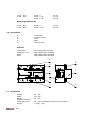
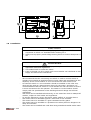
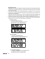
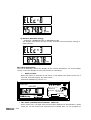
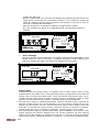
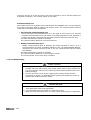
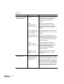
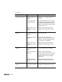
DRM1250D – 20/100A
DIN rail three phase four wire energy meter
User manual
®
2007
1.1
Safety instruction
1.2
Foreword
1.3
Performance criteria
1.4
Specifications
1.5
Basic errors
1.6
Description
1.7
Dimensions
1.8
Installation
1.9
Operating
1.10
Troubleshooting
1.11
Technical support
1.1 Safety instructions
Information for Your Own Safety
This manual does not contain all of the safety measures for operation of the equipment
(module, device), because special operating conditions, and local code requirements or
regulations may necessitate further measures. However, it does contain information
which must be read for your own personal safety and to avoid material damages. This
information is highlighted by a warning triangle and is represented as follows,
depending on the degree of potential danger.
Warning
This means that failure to observe the instruction can result in death, serious injury or
considerable material damage.
Caution
This means hazard of electric shock and failure to take the necessary safety
precautions can result in death, serious injury or considerable material damage.
Qualified personnel
Commissioning and operation of the equipment (module, device) described in this
manual may only be performed by qualified personnel. Qualified personnel in the
sense of the safety information contained in this manual are persons who are
authorized to commission, start up, ground and label devices, systems and circuits
according to safety and Regulatory standards.
Use for the intended purpose
The equipment (device, module) may only be used for the application cases specified in
the catalog and the user manual and only in connection with devices and components
recommended and approved by DMMetering.
Proper handling
The prerequisites for perfect, reliable operation of the product are proper transport,
proper storage, installation and assembly, as well as proper operation and
maintenance. When operating electrical equipment, certain parts of this equipment
automatically carry dangerous voltages. Improper handling can therefore result in
serious injury or material damage.
®
Use only isolated tools.
Do not connect while circuit is live (hot).
Place the meter only in dry surroundings.
Do not mount the meter in an explosive area or expose the meter to dust, mildew and
insects.
Make sure the used wires are suitable for the maximum current of this meter.
Make sure the AC wires are connected correctly before activating the current/voltage to
the meter.
Do not touch the meter connecting clamps directly with your bare hands, with metal,
blank wire or other material as you will have the chance of an electric shock and a
possible chance for health damage.
Make sure the protection cover is placed after installation.
2007
Installation, maintenance and repair should only be done by qualified personnel.
Never break the seals and open the front cover as this might influence the functionality
of the meter, and will avoid any warranty.
Do not drop, or allow physical impact to the meter as there are high precision
components inside that may break.
Exclusion of liability
We have checked the contents of this publication and every effort has been made to
ensure that the descriptions are as accurate as possible.
However, deviations from the description cannot be completely ruled out, so that no
liability can be accepted for any errors or omissions contained in the information
given. The data in this manual are checked regularly and the necessary corrections
are included in subsequent editions. We are grateful for any improvements that you
care to suggest.
Subject to technical modifications without notice.
Copyright
Copyright DMMetering March 2007 All rights Reserved.
It is prohibited to pass on or copy this document or to use or disclose its contents
without our express permission. Any duplication is a violation of the law and subject
to criminal and civil penalties. All rights reserved, particularly in the event of a
patent award or utility model registration.
Registered trademarks
DMMetering® is registered trademark of Inepro Industries Ltd – member of the
Inepro Group. The other names appearing in this manual may be trade names the
use of these names by third parties for their own purposes may infringe the rights
of the owners.
1.2
Foreword
Thank you for purchasing the DMMetering DRM1250D DIN rail three phase four wire
energy meter. The DMMetering DRM1250D energy meter is the most advanced type
electronic kWh meter available at the market. With the DMMetering product range
we have introduced a large scale of energy meters on the market suitable for 110V
AC to 400V AC (50 or 60Hz). Besides the normal energy meters we also developed
our own pre-paid meters with chip card, chip card re-loaders and a complete PC
management control system. For more information on other product please contact
our sales department at [email protected] or [email protected].
Although we produce the DMMetering DRM1250D meter according to IEC 62053-21
and our quality inspection is very accurate there might always be a possibility that
your product shows a fault or failure for which we do apologize. Under normal
conditions your product should give you years of benefit and pleasure. In case there
is problem with the energy meter you should contact your dealer immediately. All
energy meters are sealed with a special seal. Once this seal is broken there is no
possibility to claim for warranty. Therefore NEVER open an energy meter or break
the seal of the energy meter. The warranty time is 6 months, after installation, and
only valid for construction faults.
®
2007
1.3
Performance criteria:
Operating humidity
Storage humidity
Operating temperature
Storage temperature
International standard
Accuracy class
Protection against penetration
of dust and water
Insulating encased meter of
protective class
≤ 75%
≤ 95%
-10°C - +50°C
-30°C - +70°C
IEC 62053-21
1
IP51
II
1.4 Specifications:
Nominal voltage (Un)
Operational voltage
Insulation capabilities:
- AC voltage withstand
- Impulse voltage withstand
Basic current (Ib)
Maximum rated current (Imax)
Operational current range
Over current withstand
Operational frequency range
Internal power consumption
Test output flash rate (PULSE LED)
Remote output flash rate (SO LED)
Test pulse output rate (pins 7 & 8)
Remote pulse output rate (pins 15
& 16)
Power supply indicator (L1, L2 &
L3 LED)
Consumption indicator (PULSE &
SO LED)
Data display mode
Data
Data
LED)
Data
Data
communication port
communication indication (COM.
transportation speed
save
230/400V AC (3~)
161/279 – 300/520V AC (3~)
2KV for 1 minute
6KV – 1.2µS waveform
20A
100 A
1A - 100A
3000A for 0.01s
50Hz ±10%
≤2W / 10VA per phase
160 impulses per kWh
10 impulses per kWh
160 pulses per kWh
10 pulses per kWh
Meter is connected and working OK.
Flashing at load running.
5+2 digits or 6+1 digits for option LCD (5+2
digits for default).
Far infrared and RS485 port.
Flashing during the data communication.
1200bps.
The data can be stored more than 20 years
when power cut.
1.5 Basic errors:
With balanced loads
0.05Ib
0.1Ib
®
2007
Cosφ = 1
Cosφ = 0.5L
Cosφ = 0.8C
±1.5%
±1.5%
±1.5%
0.1Ib - Imax
0.2Ib - Imax
Cosφ = 1
Cosφ = 0.5L
Cosφ = 0.8C
±1.0%
±1.0%
±1.0%
With single phase load
0.1Ib - Imax
0.2Ib - Imax
1.6
Cosφ = 1
Cosφ = 0.5L
±2.0%
±2.0%
Description
A
B
C
D
E
Front panel
Protection cover
Cover
Base
Security hasp
Material
Front panel
Protection cover
Cover
Base
PC inflammable retarding
ABS inflammable retarding
ABS inflammable retarding
ABS inflammable retarding
E
4
1
2
5
3
6
L1
L2
8
7
6
5
+
TEST
-
B
RS485
A
4
3
B
E
1.7
Dimensions
Height
Width
Depth
88 mm
125 mm
68 mm
Distance between
installation holes
Weight
®
2007
C
SO
N
L3
L2
16
L1
15
13
N
D
N
14
12
L3
L3
11
L2
L1
A
S O L1 L2 L3 PULSE Rev.
L2
10
8
N
1
IEC620 53-2 1
2 3 0 /40 0 V 2 0 ( 1 00) A 5 0H z
L E D /TE ST 1 6 0 i m p / k Wh
1 0 i m p / kW h
SO
3
NO.
COM .
L1
9
7
L3
DRM1250D
3 PHASE 4 WIRE ENERGY METER
DMMetering
B
B
63 mm (installation mode in front of board)
0.75Kg (net)
B
4
1
2
5
3
6
L1
L2
8
N
8
7
6
5
+
T ES T
-
B
R S4 8 5
A
SO
4
3
N
L3
L2
L1
L3
11
N
14
12
1.8
N
L2
10
L3
SO L1 L2 L3 PULSE Rev.
1
IEC62053-21
2 30 /4 0 0 V 20 (1 00 )A 50 H z
LED /TES T 16 0 i m p/k Wh
1 0 i mp/ k Wh
SO
3
N O.
COM .
L1
9
L2
L1
DRM1250D
3 PHASE 4 WIRE ENERGY METER
DMMetering
7
L3
15
16
13
Installation
CAUTION
Turn off and lock out all power supplying the energy meter and the
equipment to which it is installed before working on it.
Always use a properly rated voltage sensing device to confirm that power is
off.
WARNING
-
-
®
2007
Installation should be performed by qualified personnel familiar with
applicable codes and regulations.
Use isolated tools to install the meter.
Fuse or thermal cut-off or single-pole circuit breaker can’t be fitted on the
supply line and not the neutral line.
We recommend that the connecting wire which is used to connect meter to
outside circuit should be sized according to local codes and regulations for the
ampacity of the circuit breaker or over current device used in the circuit.
An external switch or a circuit-breaker should be installed on the inlet wire,
which will be used as a disconnection device for the meter. And there it is
recommendation that the switch or circuit-breaker be near the meter so that it
is more convenience for the operator. The switch or circuit-breaker should
comply with the specifications of the building electrical design and all local
regulations.
This meter can be installed indoor directly, or in a meter box which is waterproof
outdoor, subject to local codes and regulations.
To prevent tampering, secure the meter with a padlock or a similar device.
The meter has to be installed against a wall which is fire resistant.
The meter has to be installed in a good ventilated and dry place.
The meter has to be installed in a protection box when placed in dangerous or
dusty environment.
The meter can be installed and used after being tested and sealed with a letter
-
-
press printing.
The meter can be installed on a 35mm DIN rail or direct on a meter board with
screws.
The meter should be installed in an available height so that it is easy to read.
When the meter is installed in an area with frequent surges due to e.q.
thunderstorms, welding machines, inverters etc, protect the meter with Surge
Protection Devices
After finishing installation, the meter must be sealed to prevent tampering.
Connection of the wires should be done in accordance with the underneath
connection diagram.
+
8
TEST
7
4
SO
3
B
6
RS485
5
L1
L2
L3
N
7 and 8
5 and 6
3 and 4
1.9
A
N
N
L3
L3
L2
L2
L1
L1
L1 phase wire
L2 phase wire
L3 phase wire
Neutral wire
Test pulse output contact
RS485 communication contact
Remote pulse output contact
Operating
Working indication
On the DRM1250D’s front panel, there are three power indicating LED which have
different color from each other. The yellow LED represent L1 phase; the green LED
represent L2 phase; the red LED represent L3 phase. When any phases work normally,
the LED representation will burn. When any phases have failure or no power, the LED
will turn off.
Consumption indication
On the DRM1250D’s front panel, there are two impulse indicating LED which have
different color from each other. The white LED is PULSE LED (When it burns, it is red.)
The green one is SO LED. When the load is running, these LED will flash to indicate the
load is consuming power. The more quickly LED flash, the more consumption there is.
The PULSE LED’s flash rate is 160 impulses per kWh. And the flash rate of SO LED is 10
impulses per kWh.
Communication indication
On the front panel of DRM1250D, there is a COM. LED. When the data communicate
between the far infrared port and RS485 port with outside equipment, the LED will
flash.
®
2007
Reading the meter
DRM1250D has a LCD. The display can display several electric energy data and meter
information. The 2 display modes are: recycle mode and key-press one by one outside
mode. Via the meter’s far infrared port or RS485 port, the display mode can be selected
to program the meter.
When the meter defaults the recycle display after the production, the recycling period
is 5 seconds. The recycling period can be setup in the 1-99 seconds, via the meter’s far
infrared port or RS485 port.
When the recycling period is set to 0 second, the display mode will be changed to the
key-press one by one outside mode. Then to connect an open-button between the
terminal 1 and 2, to press this button once, the display data will be the new one.
The meter can display up most 4 items, whether how is the display mode, the display
data will be done as per the following order. The data needed can be displayed after
programming via the meter’s far infrared port or RS485 port.
a) Meter number
- Indication: NNNNNNNNNNNN
12 digits displayed in a high and low display.
Example meter number 698532364526
b) User number
- Indication: NNNNNNNNNNNN
12 digits displayed in a high and low display
Example user number 260935625408
c) Current total energy
- Indication: NNNNN.NN kWh or NNNNNN.N kWh
The display is as follows on two screens.
Example total energy is 45748.91 kWh.
®
2007
kWh
d) Reverse direction energy
- Indication: NNNNN.NN kWh or NNNNNN.N kWh
The display is as follows on two screens. Example reverse direction energy is
8456.78 kWh.
kWh
The other instructions
The LCD of DRM75D, beside the display of the normal information, for some sudden
issues, it can also display several instructions for reminding.
Meter version
- When the meter re-switches on the power, it will display the meter version for 5
seconds, and then display the other items.
- Indication DMMetering version 1.0
DRM1250D
3 PHASE 4 WIRE ENERGY METER
DMMetering
®
2007
COM.
SO L1 L2 L3 PULSE Rev.
1
IEC62053-21
230/400V 20( 100)A 50Hz
LED /TEST 160 i mp/ kWh
10 i mp/ kWh
SO
3
NO.
(
)
The meter communication address Meter ID
- Every meter has a 12 digits sole communication address for identification, called
Meter ID. Via the meter’s far infrared port or RS485 port, we can program to
modify the Meter ID.
- When to modify Meter ID, the meter will display the backward 6 digits of the new
Meter ID for 30 seconds for confirmation outside. If you confirm to modify the
Meter ID, please press the button outside in 30 seconds. If the time is over 30
seconds, it defaults No Modification.
- After the production, the Meter ID defaults 12 digits meter number.
- E.g. The modified new Meter ID is 698532364528. The backward 6 digits is
364528.
DRM1250D
3 PHASE 4 WIRE ENERGY METER
DMMetering
COM.
DMMetering
®
1
IEC62053-21
230/400V 20( 100)A 50Hz
LED /TEST 160 i mp/ kWh
10 i mp/ kWh
SO
3
NO.
Error message
- When the display indicates EEP there is a problem with the internal EEPROM. If this
display does not return to normal, or happens frequently, please contact your
dealer to replace the meter to prevent any damage on your meter.
DRM1250D
3 PHASE 4 WIRE ENERGY METER
SO L1 L2 L3 PULSE Rev.
COM.
SO L1 L2 L3 PULSE Rev.
1
IEC62053-21
230/400V 20( 100)A 50Hz
LED /TEST 160 i mp/ kWh
10 i mp/ kWh
SO
3
NO.
Pulse output
DRM1250D DIN rail energy meter is equipped with a pulse output which is fully
separated from the inside circuit. That generates pulses in proportion to the measured
energy. They are test pulse output (pins 7 & 8) and remote pulse output (pins 3 & 4).
Usually, the test pulse output is used as testing accuracy or reading purpose in close
quarters. And the remote pulse output is used as remote reading purposes.
The test pulse output is a polarity dependant, passive transistor output requiring an
external voltage source for correct operation. For this external voltage source, the
voltage (Ui) should be 5-27V DC, and the maximum input current (Iimax) should be
27mA DC. To connect the impulse output, connect 5-27V DC to connector 8 (anode),
and the signal wire (S) to connector 7 (cathode). The test pulses 160 per kWh.
The remote pulse output is a polarity dependant, passive MOSFET or an internal relay
output requiring an external voltage source for correct operation. For this external
voltage source, the voltage (Ui) should be 5-60V DC or 5-30V AC, and the maximum
input current (Iimax) should be 80mA DC or 60mA AC. To connect the impulse output,
2007
connect 5-60V DC or 5-30V AC to any one from connector 3 and 4, and the signal wire
to another connector. The remote pulses 10 per kWh.
Communication port
This model meter has equipped a far infrared port and a RS485 port, we can program
the meter’s operation data or reading via these 2 ports. The communication protocol
conforms to DL/T645-1997 Standards.
Far infrared communication port
- The far infrared communication port is on the right of LCD screen. It is infrared
wireless communication port. The TP800 hand-held programmer with TP800V2.0
version can directly communicate the data between the meter and this port.
- The data transmission speed is 1200bps.
- The communication distance is not less than 5m.
RS485 communication port
RS485 communication port is between the meter terminal 5 and 6. It is a
synchronization wire port. Installing software in PC, via RS232/RS485 adapter,
connecting the meter terminal 5 and 6, PC can communicate with the meter
immediately.
- The data transmission speed is 1200bps.
- The communication distance is not less than 1000m.
- The most quantity of the main wire is 128pcs.
-
1.10 Troubleshooting
CAUTION
During repair and maintenance, do not touch the meter connecting clamps
directly with your bare hands, with metal, blank wire or other material as
you will have the chance of an electricity shock and a possible chance for
health damage.
Turn off and lock out all power supplying the energy meter and the
equipment to which it is installed before opening the protection cover to
prevent the hazard of electric shock.
WARNING
®
2007
Maintenance or repair should be performed by qualified personnel familiar
with applicable codes and regulations.
Use insulated tools to maintain or repair the meter.
Make sure the protection cover is in place after maintenance or reparation.
Problem
Check
Solution
No light for the
Power supply
indicator (L1, L2 &
L3 LED).
Is AC power supply
connected to the
meter ?
Check switch or circuit-breaker
and fuse or thermal cut-off.
Is the L1, L2, L3 and
N connecting
correct ?
Reinstall terminal screws on the
L1, L2, L3 and N. Make sure all
screws are fixed. Than there
should be a 230V 50Hz AC voltage
between the terminal screws on
the N and L1 or L2 or L3, when
power supply is input.
Is the terminals 9,
10, 11, 12, 13 and
14 connecting
correct ?
Reinstall terminal screws on the
9, 10, 11, 12, 13 and 14. Make
sure all screws are fixed. Than
there should be a 230V 50Hz AC
voltage between the terminal
screws on the N and 9 or 11 or 13,
when power supply is input.
Maybe there is a
fault in the inside
circuit.
Please contact your technical
supporter to replace this meter.
Is the load
running ?
Only when load is running, this
LED will flash.
Is the operating
power too low ?
If the operating power is too low,
the spacing interval of the flashes
will take some more time, this is
why it seems like the LED isn’t
burning.
Maybe there is a
fault in the inside
circuit.
Please contact your technical
supporter to replace this meter.
Is there a power
supply inside the
meter ?
Check that the power supply
indicator ( L1, L2 & L3 LED ) is
burning.
Does any
equipment outside
communicate with
the meter ?
Only when the communication
between the meter’s infrared port
or the RS485 port and the
equipment outside, the LED will
blink.
Maybe there is a
fault in the inside
circuit.
Please contact your technical
supporter to replace this meter.
No light for the
consumption
indicator (PULSE &
SO LED).
No light for the
communication
indicator (COM.
LED).
®
2007
Continue.
Problem
Check
Solution
No recycle display
of every electricity
data or information
on LCD screen.
Is the period set
for the recycle
display too long ?
The recycle period is set too lont,
it will be misdeemed not to be
recycle display. So reset the
reasonable period in the range of
1-99 seconds.
Is the display mode
set to the button
display one by one
outside ?
Check if the recycle display period
is 0 second or not. The period 0
second means to have set to the
button display one by one
outside, please re-set the
reasonable period in the range of
1-99 seconds.
Is it set to the
only-one item
display permitted ?
The LCD display data can be
option to program the meter and
re-choose the needed data via the
meter’s infrared port or the
RS485 port.
Is it set to only
display “EEP” Error
message ?
Maybe there is a fault in the inside
circuit, Please contact your
technical supporter to replace this
meter.
Is the Meter ID
correct ?
Check and use the correct the
Meter ID. After the meter finish
the production, the Meter ID
defaults to 12 digits meter
number.
Is the
communication
distance too long ?
Shorten the communication
distance between the reading
equipment outside and the meter.
Keep sure it is not more than 5m.
Is the
communication
protocol correct ?
Please contact the technical
support department to get the
meter communication protocol, or
use the TP800 hand-held
programmer with TP800V2.0
version software.
Maybe there is a
fault in the inside
circuit.
Please contact your technical
supporter to replace this meter.
No communication
of the infrared
wireless data with
the meter.
®
2007
Continue.
Problem
Check
Solution
No communication
of RS485 wire data
with the meter.
Is the Meter ID
correct ?
Check and use the correct the
Meter ID. After the meter finish
the production, the Meter ID
defaults to 12 digits meter
number.
Is the
communication
distance too long ?
Shorten the communication
distance between the reading
equipment outside and the meter.
Keep sure it is not more than
1000m.
Is the connection
wire to RS485 main
wire too much ?
The equipment to connection with
RS485 main wire is not more than
128 pcs.
Is the RS485 port
connection correct ?
The correct connection is: the A
signal wire of RS485 main wire to
the meter terminal 5, the B signal
wire of RS485 main wire to the
meter terminal 6.
Is the
communication
distance too long ?
Please contact the technical
support department to get the
meter communication protocol, or
use the TP800 hand-held
programmer with TP800V2.0
version software.
Maybe there is a
fault in the inside
circuit.
Please contact your technical
support department to replace
this meter.
Is the meter
working correctly
after the Meter ID
modification ?
The correct working is: after the
Meter ID modification, the meter
will display the backward 6 digits
of the new meter ID for 30
seconds. During the 30 seconds,
please confirm the modification
via pressing the buttons outside
(the button outside must connect
to the meter terminal 1 and 2).
No modification for
the Meter ID.
®
2007
Continue.
Problem
Check
Solution
The LCD energy
register can’t run.
Is there a power
supply inside the
meter ?
Check that the power supply
indicator ( L1, L2 & L3 LED ) is
burning.
Is the operating
power too low ?
If the operating power is too low,
the spacing interval of the pulses
will take some more time, this is
why it seems like the LCD energy
register can’t run.
Maybe there is a
fault in the inside
circuit.
Please contact your technical
supporter to replace this meter.
Is DC power supply
connected to the
meter ?
Check the external voltage source
(Ui) is 5-27V DC.
Is the connecting
correct ?
Check correct connecting:
connect 5-27V DC to connector 8
(anode), and the signal wire (S)
to connector 7 (cathode).
Maybe there is a
fault in the inside
circuit.
Please contact your technical
supporter to replace this meter.
Is power supply
connected to the
meter ?
Check the external voltage source
(Ui) is 5-60V DC or 5-30V AC.
Is the connecting
correct ?
Check correct connecting:
connect 5-60V DC or 5-30V AC to
any one from connector 3 and 4,
and the signal wire to another
connector.
Maybe there is a
fault in the inside
circuit.
Please contact your technical
supporter to replace this meter.
Maybe there is a
fault in the inside
circuit.
Please contact your technical
supporter to replace this meter.
No test pulse
output.
No remote pulse
output.
Pulse output rate
wrong.
®
2007
1.11 Technical support
For questions about one of our products, please contact:
-
DMMetering dealer in your in your region
Your local DMMetering distributor
Email: [email protected]
www.dmmetering.com
®
2007
Inepro Industries Ltd.
Room 3208, Central Plaza
18 Harbour Road, Wan Chai
Hong Kong.
Fax: +852 2911 1200
www.inepro.com.hk
[email protected]