1
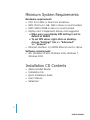
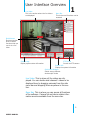
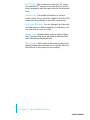
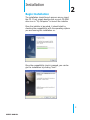
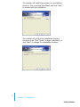
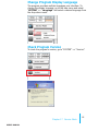
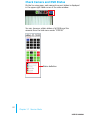
π-Vu Central Basic User ’s Manual
Version 1.6.0.8
2
| Table of Contents
Table of Contents
Terms and Conditions
Minimum System Requirements
Chapter 1 User Interface Overview
Chapter 2 Installation
Chapter 3 Using the Setup Wizard
Chapter 4 Add a NVR
Chapter 5 PTZ Configuration
Chapter 6 Intelligent Detection
Chapter 7 Users and Groups
Chapter 8 Event Handling
Chapter 9 Configure E-Map
Chapter 10 Set up Multiple Monitors
Chapter 11 Default Start Config
Chapter 12 Event Servers
Chapter 13 Using the Main Program
Chapter 14 Event Monitor
Chapter 15 Playback
Chapter 16 E-map Monitor
Chapter 17 Service Mode
3
5
6
8
13
14
17
20
26
30
32
35
36
39
47
57
59
64
66
Terms and Conditions
This End-user License Agreement is a legally binding agreement between you (either an individual or a single entity) and our company for the software product, which may include associated software components, media, printed materials, and online or electronic documentation.
By installing, copying, or otherwise using the product covered by this EULA, you agree to be
bound by the terms of this EULA. If you do not agree to the terms of this EULA, do not install
or use the product, instead you may return it, within 30 days, along with all associated material to your place of purchase for a full refund. The product is protected by copyright laws and
international copyright treaties, as well as other intellectual property laws and treaties. Note
that the product is licensed to you, not sold. The license you have been granted is identified
by the Software License Code on the License Certificate.
* Installation and Use *
The company hereby grants you the right to install and use the software product with the
following restrictions:
1. The product may be installed on as many computers that meet the hardware and software
requriements.
2. The product may only be used on computers running operating systems for which the product was designed.
3. You can and may only use the product in connection with video hardware equipment for
which you have rightfully obtained the corresponding Device License Keys from our authorized
dealer or from our company’s web site
* Copyright *
All titles, including but not limited to copyrights, in and to the software product and any
copies thereof are owned by our company. All rights not expressively granted are reserved by
our company.
* No Warranties *
The company expressly disclaims any warranty for the product. The software product and
any related documentation is provided as is without warranty of any kind, either express or
implied, including, without limitation, the implied warranties or merchantability, fitness for a
particular purpose, or non-infringement.
3
user’s manual
The entire risk arising out of use or performance of the software product remains with you as
the user. You are notified that the product, when used with certain equipment or other software, may enable you to perform surveillance actions and data processing which are likely
to be restricted by or contrary to applicable law, including without limitation data privacy and
criminal law. The sole responsibility for verification of your use against compliance with applicable law lies with you as the user.
* Limitation of Liability *
The provisions of this paragraph are in effect to the maximum extent permitted by applicable
law. In no event shall Seenergy or its suppliers be liable for any special, incidental, indirect,
or consequential damages whatsoever (including, without limitation, damages for loss of business profits, business interruption, loss of business information, or any other pecuniary loss)
arising out of the use of or inability to use the software product or the provision of or failure
to provide proper support, even if our company has been advised of the possibility of such
damages. Absent any willful misconduct or gross negligence, Seenergy's entire liability under
any provision of this agreement shall be limited to the amount actually paid by you for the
product.
* Miscellaneous *
(a) You may make as many copies of the software product as may be necessary for backup
and archival purposes.
(b) You may distribute copies of the software product to third parties.
(c) You may not reverse engineer, decompile, or disassemble any of the software product’s
components except to the extent permitted by applicable law which cannot be contractually
waived.
(d) You may permanently transfer all of your rights for this product, provided the recipient
agrees to the terms of this agreement.
* Termination *
Without prejudice to any other rights, our company may terminate this license agreement
if you fail to comply with its terms and conditions. In such event you must destroy all copies
of the software product.
* Governing Law *
These License Terms and the contract between you and our company are governed by Taiwanese law and the sole and proper forum for the settlement of disputes hereunder shall be
the Taiwan Shihlin District Court.
4
user’s manual
Minimum System Requirements
Hardware requirement:
• CPU: P4-2.4Ghz or Dual Core and above
• RAM: Minimum 1 GB, 2GB or above is recommended
• HDD: SATA 200GB or above is recommended
• Display card: Independent display card suggested
•Make sure your display DPI setting is set to
default at 96DPI
•To set DPI value, right-click on desktop,
choose “Settings” tab >> “Advanced”
>> “General”
• Ethernet interface: 10/100Mb Ethernet card or above
Software requirement:
• OS: Windows XP SP2, Windows Vista, Windows 7,
Windows 2003
Installation CD Contents
•
•
•
•
•
Adobe Acrobat Reader
Installation File
Quick Installation Guide
User’s Manual
Datasheet
5
user’s manual
User Interface Overview
Live Video
This is the section where the live videos
are displayed
1
Menu Bar
This is where all functions can be
accessed
Quick Access
Quick access buttons to certain
functions that you
can do to a live
video
System Logs
Display system status information
PTZ Control
Control the PTZ camera
System Info
Display the system information
Split Video Windows
Switch among different
window split modes
Live Video: This is where all the videos are displayed. You can decide what channels’ videos to be
displayed here by dragging cameras from the side
menu bar and dropping them anywhere in this section.
Menu Bar: This is where you can access all functions
of the software. Camera list and device status information are also available from the menu bar.
6
User’s manual
PTZ Control: This is where you can pan, tilt, zoom
the selected PTZ camera. Functions such as preset
point nevagation and auto pan can also be accessed
here
System Info: It provides information of current
system time, who is currently logged in and the CPU
usage that the software is currently consuming.
Split Video Windows: You can change the video split
windows with you desire depends on how many videos you wish to view at a time.
System Logs: System status such as motion detection, functions that were accessed or settings that
were altered are displayed here.
Quick Access: Each video window comes with quick
access buttons which allows you to quickly take certain actions to the video you are viewing.
7
Chapter 1
User Interface Overview
user’s manual
Installation
Begin Installation
2
The installation should launch as soon as you insert
the CD. If not, simply double-click on your CD-ROM
drive icon in “My Computer” to launch the installer.
Once the installer is launched, it should start by
checking the compatibility with the operating system
you are running this installation on.
Once the compatibility check is passed, you can begin the installation by clicking “next”.
8
User’s manual
The installer will install the program in a pre-defined
directory. You can accept the default and click “Next”
to proceed with the installation.
The installer will confirm the installation directory
one more time. Click “Install” to begin installation, or
click “Back” to change the installation directory.
9
Chapter 2
Installation
user’s manual
The installer will display the installation process.
Once the installation is complete, click “Finish” to
exit out the installer.
Chapter 2
user’s manual
Installation
10
Change Installtion Directory
If you wish to install the program other than its
pre-defined directory, click “Change” at the prompt
where it displays the pre-defined directory,
You will be prompted with a new window in which
you can type in the new directory at the bottom.
Or you can choose the directory from the drop down
menu.
11
Chapter 2
Installation
user’s manual
If you need to install in a folder that doesn’t exist
yet, click “Create New Folder” to create it.
Start the CMS software
After the prgram is successfully installed on the PC,
there are two ways to start it.
• Start it from the “Start” menu:
Simply go to “Start” >> “All Programs” >> “Seenergy” >> “π-Vu Central Basic”>> “π-Vu Central Basic
• Start it from the desktop:
The program automatically creates a shortcut icon on
your desktop after it’s successfully installed. Simply
double-click the icon to launch the program.
* You should run the “Setup Wizard” before
launching the CMS software. The Setup Wizard is
a separate program which you can launch it the
same way you launch the CMS software (from
Start menu). The purpose of the Setup Wizard is
to help users with certain preliminary settings in
order for the program to work with NVR network
video recorder.
Chapter 2
user’s manual
Installation
12
Using the Setup Wizard
3
Menu options -Lists all the menu
options available in
the Setup Wizard
Configuration Window -Displays configuration
parameters of the selected menu option
It’s necessary to use the Wizard
The majority of the settings of the CMS software relies on its Setup Wizard. It’s necessary that you run
the wizard prior to using the CMS software.
With the Setup Wizard, you are able to:
•
•
•
•
•
•
•
•
Add/Remove/Edit one or more NVRs
Configure PTZ preset points
Configure Intelligent Detection
Configure user privileges
Configure how events are handled
Configure E-map
Configure multiple monitors
Configure event actions
13
user’s manual
Add a NVR
4
Connect the program with NVR
The main purpose of the CMS software is to manage multiple NVRs. Before it can be done, you would need to tell the
program which NVR you need it to manage. You do that by
adding one or more NVRs to the program through the Setup
Wizard.
Automatic Search:
The Setup Wizard is able to find NVR on your local network
automatically. Simply go to “SVR Settings” >> “Manual
Settings” in the Setup Wizard, and click the search button to
locate NVRs that are placed on your local network.
14
User’s manual
Drag and Drop to add
Once the Setup Wizard detects NVR on the network,
they will be listed in the “Detect List”. Simply drag
one from the list and drop it in the “Advance Control
List” below to add it
You will then be prompted with its username and
password which you need to enter accordingly to
complete the action.
Add NVR Manually with Setup Wizard:
Simply click on the “Add NVR” button in the same
page to add it manually.
15
Chapter 4
Add a NVR
user’s manual
You will be asked for the information shown below
before successfully adding the NVR to the program.
Remove a NVR or Edit its Settings
Once you have one or more NVR added to the program, the
“Remove” and “Edit Settings” buttons will become available.
Simply click to select a NVR from the list on the left and
choose the corresponding button on the right.
Remove NVR
Edit settings
Chapter 4
user’s manual
Add a NVR
16
PTZ Configuration
5
Video Preview
You can
get a video
preview of
the selected
camera here
Select NVR and
camera
Select which
NVR and which
camera from the
drop-down list
PTZ Speed
Control
Adjust the
increment
of the PTZ
movements
PTZ Preset
Points List
List of all PTZ
preset points
of the selected
camera
PTZ Preset Point Name
Add a new name or alter an existing
name of a preset point
PTZ Control Panel
Use this panel to define a new
preset point or make change to an
existing one
Synchronize or Add New PTZ Preset Points
You can synchronize PTZ settings from all cameras connected to
the NVR on the network or you can create and add new PTZ preset
points to those cameras through the Setup Wizard.
Select a NVR first
Simply select a NVR from the drop-down menu first
and then select a camera to synchronize or add new
PTZ preset points.
Then select a camera connected to
the selected NVR
17
user’s manual
Use the provided PTZ control panel to define a PTZ
preset point. You may change the speed of the PTZ
movements if you will.
Video Preview
You can get a video preview
of the selected camera here
PTZ Speed Control
Adjust the increment of
the PTZ movements
PTZ Control Panel
Use this panel to define a new
preset point or make change to an
existing one
You can get a list of the preset points that have been
added to the camera as well as the opening slots
that are available which you can add new preset
points to later on.
Slot configured with a PTZ
preset point
Slot that has not been
configured with a PTZ
preset point
Chapter 5
user’s manual
PTZ Configuration
18
Configuring PTZ Preset Sequence
You can configure the PTZ preset sequence after you create
and define PTZ preset points for the cameras. To configure
PTZ sequence, open the setup wizard and go to NVR setting
>> PTZ Config >> PTZ sequence
You can see a list of the preset points that were added previously under the “Preset info” pane on the left
(see below step 3), which you can then move ones
to the right (Preset Sequence pane) for sequence
viewing
1.
2.
5.
6.
Set Dwell Time
Finally set the dwell
time for sequencing
view among each
point
3.
Move the ones to the right
Move the preset points to
the list on the right using
the
which they will be
used for PTZ sequencing
19
Chapter 5
4.
5.
Select an NVR first
Select an NVR from
the drop down menu
first
Select a PTZ Camera
Select a PTZ camera
to configure PTZ sequence
Select Preset Points
The previously configured preset points will
be listed on the left
Adjust Sequence Order
You can use the
or
buttons to
adjust the sequence
orders
PTZ Configuration
user’s manual
Intelligent Detection
Setting
6
Device List
Lists of all NVR
and cameras
Motion Enabled List
Enable receiving
motion trigger sent
from the NVRs
Intelligent Detection List
Configuration status of the intelligent detection functions on each
camera
Video Preview
Video preview
of the selected
camera from the
above list
Intelligent Detection Functions
The program can be configured with multiple intelligent detection functions which can then be used to
alert users when detecting something abnormal in
the scene. The functions are as below:
•
•
•
•
Motion Detection
Malicious Attack (camera tampering)
Object Loss Detection
Tripwires
20
User’s manual
To enable and configure one of the intelligent detection functions for one or more cameras, click and
drag the camera from the “Device List” onto the
“Intelligent Detection List”:
drag and drop
Double click on the desired channel in the “Intelligent
Detection List” to enable configuration:
1.
Double click
2.
Configuration
Finally, select the desired intelligent detection function from the “Event Mode” drop-down and make
sure “Enable” is ticked:
21
Chapter 6
Intelligent Detection
user’s manual
Configuring Motion Detection
To configure motion detection, select “Motion Detection” from the “Event Mode” drop-down menu:
Next, select the desired sensitivity for motion detection:
By default, the program does not have any area
configured for motion detection, you can quickly click
on “Select All” to enable the whole area for motion
detection. You can always click on “Clear All” at anytime to start over:
Chapter 6
user’s manual
Intelligent Detection
22
To configure a particular area for motion detection,
simply click and hold down the mouse left button and
move diagonally to select a desired area. You can do
it repetitively to configure multiple areas for motion
detection:
The configured areas will then be highlighted on the
video with green cell boxes:
Finally, click “Submit” to save the configuration:
23
Chapter 6
Intelligent Detection
user’s manual
Configuring Malicious Attack
This is the function that when the camera is being
physically tampered (sabotaged/or viewing area gets
blocked), the CMS can detect such behavior and
send out alert to the administrator. To enable this
fuctions, simply select “Malicious Attack” from the
“Event Mode” drop-down menu and click “Submit”:
Configuring Object Loss
To select this function, select “Object Loss” from the
“Event Mode” drop-down menu and then click and
hold down the mouse left button and move diagnonally to draw an area (select the object in the scene)
for object loss detection. The selected area(s) will be
highlighted in red color like shown below:
Chapter 6
user’s manual
Intelligent Detection
24
Configuring Tripwire
To configure tripwire, select “Tripwire” from the
“Event Mode” drop-down menu. Click and hold down
the mouse left button to draw a line on the video:
To re-arrange the position of the line, hover the
mouse cursor onto either tip end and once you see
the color of the cell box becomes green, click and
hold down the mouse and move the cell box to a
desired new position:
The tripwire function can be configure to detect
traffic coming from one way or both. Bi-directional
detection is enabled by default; to configure detection for one way only, click the cell box in the middle
of the line. Click again to change direction.
25
user’s manual
Users and Groups
7
Users and Groups Configuration
The section allows users to add new users and customize each of their access privilege by assigning
them to different user groups. The purpose of this
function is to limit the number of people to have access to the program, hence, having access to view
live videos, playback videos or altering settings of
the program.
Once you add users to the program, you will be
prompted to enter the username and password of a
valid user account.
* There is no user account configured
for the program by default.
The privileges of the “Admin” and the
“Guest” groups are not configurable
and the “Guest” account is configured
with the “view only” privilege”.
26
User’s manual
Add a New User
To add a new user, simply click on the “add new
user” button available at the upper-right hand corner
in the “User/Group Config” page.
Add a new user
This opens up a new window for you to enter the
detail information of the user you are creating.
* The “Username”, “Password” and
“Confirm Password” fields are required when creating a new user
account. The rest of the fields are
optional.
* You can click the “Check” button to
check if the username you are creating for the new account has been
used by another account.
A “+” will appear next to the group indicating a user
has been added to that particular group. Click on the
“+” to expand the group and all users will be displayed.
27
Chapter 7
Users and Groups
user’s manual
The “Remove” and “Edit” buttons will become available once a user has been created.
Click the “Remove” button to remove an existing
user, or the “Edit” button to edit setting of an existing user account
Remove an user
Edit setting of an existing
user account
Edit Group Privilege
To edit access privilege of a particular user group,
simply select a group first then click the “Edit Group”
button.
Edit privilege of a goup
Chapter 7
user’s manual
Users and Groups
28
This opens up the the group privilege configuration
dialog.
Select a group from the drop-down menu and check
which function(s) this group has permission to.
Select a group
Select functions to
grant access to
29
Chapter 7
Users and Groups
user’s manual
Event Handling
8
General event
conditions
NVR-specific
event conditions
Event Handling Configuration
Here you can define what consititutes an event with
pre-defined conditions and what actions to be taken
when these conditions are met.
The conditions are devided into two categories:
• General event conditions
Conditions such as settings being altered
• NVR-specific event conditions
Conditions such as motion detection
30
User’s manual
To enable a condition for event trigger, simply tick
the checkbox of a particular condition.
Event Condition
Tick the checkbox to enable
Double-click pulls down the
event servers
Event Servers
Tick the checkbox to enable
Double-click on any condition pulls down the event
servers which users can choose to use for that particular condition.
The event servers can be considered as actions that
are taken place when events are triggered.
31
Chapter 8
Event Handling
user’s manual
Configure E-Map
9
Main Map
The main map
which displays locations of all NVRs
Sub-maps
Each sub-map displays the near-by
area of a particular
NVR which shows
locations of all
cameras connected
to it
The E-Map
The program provides two-layered e-map which the
top layer displays the location of all NVRs and the
second layer (sub-map) displays locations of all cameras connected to one NVR.
* There are 16 sub-maps and one for each NVR.
This function is particularly useful when motion detection is configured. You can simply place the e-map
on one monitor and whenever there is motion detected, the NVR will be highlighted on the map and
live video will be displayed for live event monitoring.
32
User’s manual
Configuring The E-Map
You can replace the map of your own when configuring e-map.
Simply double-click anywhere on the map to enlarge
it.
Double-click to
enlarge the map
and double-click on the enlarged map again to open
the dialog which lets you locate the new map file.
You will need to select a map file that is in the JPEG
file format.
Double-click to
replace the map
Locate the new map file from the local computer
33
Chapter 9 Configure E-Map
user’s manual
Once the new map is in place, move the red dots on
the map to define locations of each NVR.
Drag and move the
red dot to define
location of a NVR
Click the “Save” button at the upper-right hand corner to save changes when you are done.
Save settings
* Use the same method described above to configure submaps for each NVR.
Chapter 9
user’s manual
Configure E-Map
34
Set up Multiple Monitors
10
Available monitors
Function Windows
If you have multiple monitors configured in the PC,
the CMS setup wizard can automatically detect such
configuration and displays the available monitors.
You can find that in the setup wizard under “General
Setting” >> “Screen Layout Config”.
You should then see the available monitors on the
right (Screen-1, Screen-2...etc).
By default, all the function windows are set to display on Screen-1.
You can then drag the desired function window and
drop it to the monitor (ex. Screen-2) you wish it to
be displayed on.
Drag and Drop
35
user’s manual
Default Start Config
11
This is a function that allows you to keep the same viewing layout pattern everytime the program starts up. The
followings can be saved for next startup:
• Viewing layout (split screen)
-Use the last layout before the program is closed
-Use one of the “patterns” defined in the main program
• Start sequence viewing by default
• Start the program with particular function pages
(if multiple monitors are present)
You can configure the program to start with a particular
viewing mode (split screen). Simply make a selection under the “Split” section:
36
Chapter 11
User’s manual
Default Start Config
You can leave the drop-down menu as is it does not
contain any selection by default. Once you start the main
program and add view “patterns” like below:
Exit the main program and go back to the config wizard.
The patterns you created should be available in the corresponding drop-down menu under the “Split” section:
If you didn’t make any selection from the drop-down
menu, the main program will automatically keep the last
split mode before the program is closed and use it for the
next startup.
37
Chapter 11
Default Start Config
user’s manual
You are also able to start sequence viewing by default
as soon as the main program starts up. To do so, make
the selection to sequence all channels, between NVRs, or
between patterns:
* Please make sure multiple NVRs are added to the program or
the “NVR SEQ” option will be unavailable
* Please make sure “patterns” have created in the main program
or the “Patter SEQ” option will be unavailable
You can also configure a particular function page to start
by default on a particular monitor by making your selection under the “Function Default Start” section:
Chapter 11
user’s manual
Default Start Config
38
Event Servers
12
Event Servers are Event Actions
The program provides four different event servers
that can be used when events are triggered.
•
•
•
•
Mail server
FTP server
Message server
Sound server
You can add up to three for each servers and pick
the one(s) you would like to use for particular
event(s).
You can get a configuration overview of all the event
servers under the “Event Action Config” page.
39
user’s manual
Configure Mail Server For Events
You can configure up to three mail servers in which
you can select later and use them for different event
trigger conditions.
When configuring an mail server, it’s essential that
you provide the following information:
• Mail server address (IP or FQDN domain name)
• Username and password for the mail server (if
required)
• Recipient’s e-mail address
To start adding a mail server, click on an item field
and the setting boxes should become availble.
Enter the mail server information and click “Submit”
to save the settings.
You may click “Test” to verify the settings prior to
saving the configurations.
Click to add or edit
Enter mail server info
Chapter 12
user’s manual
Event Servers
40
Configure FTP Server For Events
You can configure up to three FTP servers in which
you can select later and use them for different event
trigger conditions.
When configuring an FTP server, it’s essential that
you provide the following information:
• FTP server address (IP or FQDN domain name)
• FTP server port (such as port 21)
• Username and password for the FTP server (if
required)
• Path to upload the files to (if not / directory)
To start adding an FTP server, click on an item field
and the setting boxes should become availble.
Enter the FTP server information and click “Submit”
to save the settings.
You may click “Test” to verify the settings prior to
saving the configurations.
Click to add or edit
Enter FTP server info
41
Chapter 12
Event Servers
user’s manual
Configure Message Server For Events
You can configure up to three message servers in
which you can select later and use them for different
event trigger conditions.
When configuring a message server, it’s essential
that you provide the following information:
• Message server address (IP or FQDN domain
name)
• Message server port
• Username and password for the Message server
(if required)
• Text to be broadcasted
To start adding a message server, click on an item
field and the setting boxes should become availble.
Enter the message server information and click “Submit” to save the settings.
You may click “Test” to verify the settings prior to
saving the configurations.
Click to add or edit
Enter messag
server info
Chapter 12
user’s manual
Event Servers
42
Configure Sound Server For Events
You can configure the program to send warning
sound from the system’s speaker when events are
triggered.
To start adding a sound server, click on an item field
and the setting boxes should become availble.
Click to add
or edit
Click on the “folder” icon to locate the sound file. You
may select a sound file that is only in the WAV file
format.
Click to locate
sound file
43
Chapter 12
Event Servers
user’s manual
Accessing the main program
Now that you have finished configuring the main
program through its setup wizard, after saving all
the settings (which you can do so by clicking on the
“Save” button on the left pane tree menu), simply
click “Exit” to close the Setup Wizard.
To access the main program, simply click on “Main
Viewer” to exit the Setup Wizard and it will be open
the main program automatically.
You can then access the main program by doubleclicking on the short cut icon located on the desktop.
Or you can access the main program by simply go to
“Start” >> “All Programs” >> “Seenergy” >> “Pi-Vu
Central Basic”>>”Pi-Vu Central Basic”
Chapter 12
user’s manual
Event Servers
44
Using the Main Program
13
Working with the Live Video Page
This page basically provides you the ability to view,
and manage the video streams of each channel.
The program provides certain functions which helps
users to monitor effectively.
• Video Function Bar
• Side Menu Bar
• View Window Switcher
• System Information
• PTZ Control
45
user’s manual
Video Function Bar
The function bar is available for each video window.
The function bar provides the following functions:
Reconnect video
Original video ratio
Image enhancement
Turn on/off audio
Motion Detection Status
Turn on/off motion display
Take snapshot
PTZ control indicator
Camera status
Reconnect video
If you find the video is streamed at a lower frame
rate than it should or the video is simply lost, you
can click this button to re-initiate the connection with
the camera and receive the stream again.
Turn on/off audio
If the camera supports audio function, you can click
this button to receive audio from the camera.
This function is turned off by default and you can
only receive audio from one channel at a time.
Original Video Ratio
The program adjust its window size according to the
size and display ratio of the monitor. By default, videos are configured to fill up their video windows and
may not be displayed in its original ratio. Click this
button will set the video to be displayed at its original display ratio.
Chapter 13
user’s manual
Using the Main Program
46
Image Enhancement
This function improves the visibility of the video under low light conditions:
Motion Detection Status
This icon serves the function to display whether motion detection has been configured for this channel.
If it’s not configured, the icon is grayed out
If it’s configured, it will be in light grey
Turn on/off Motion Display
Once a channel is configured with motion detection,
click the same icon allows you to turn on motion display which adds highlights on moving objects in the
video. The icon will show in red when this function is
turned on.
47
Chapter 13
Using the Main Program
user’s manual
Take a Snapshot
The function allows you to take snapshots of the live
video and save them on your local computer.
Simply click on the icon, and the snapshot of the
video will be displayed in a pop-up window.
Right-click anywhere on the pop-up window will give
you the option to save the snapshot.
right-click
* The snapshot is automatically saved in a pre-defined
folder under the directory where the program is installed.
Chapter 13
user’s manual
Using the Main Program
48
PTZ Control Indicator
You are able to control one PTZ camera at a time
and this icon tells users which camera is currently
selected for PTZ action.
The video window will also be highlighted with blue
color to indicate it’s currently being selected.
PTZ icon shown in
red meaning this is
a PTZ camera, or it
would grayed out.
* If the icon indicates in red: Mouseover-video PTZ is
enabled.
highlighted with blue
color
PTZ control indicator displays in green:
digital PTZ is enabled
* Digital PTZ function is only availble for
the “non-PTZ types of cameras)
Using PTZ Control Panel
Once a video is selected for PTZ action (right-click
on a video to select), you are able to do the PTZ
with the PTZ control panel,
49
Chapter 13
Using the Main Program
user’s manual
Use Mouse-over-video PTZ
or you can simply move the mouse onto the video,
an arrow and the crosshair should be displayed.
Simply right-click on the video to pan and tilt the
camera. Use the mouse scroll button to scroll down
to zoom in and scroll up to zoom out
right-click to pan and
tilt, use mouse scroll
button to zoom in/
out
Drag and Drop to Relocate Videos
On the live view page, you can simply drag the video
to re-arrange its location or switch location with another video.
Drag a video and drop
it to a new location
Drag a video and switch
place with another video
Chapter 13
user’s manual
Using the Main Program
50
View Window Switcher
You can use this function to switch between different
view patterns and set up how videos are displayed
on the screen.
Support Two Full Screen View
The program supports two full screen view if there
are more than one monitors connected to the PC.
You can view up to 16 live video on each full screen
with configurable view patterns.
The first full screen displays videos in
full screen with its current view pattern
layout (if it’s displaying videos in a 6
split window view, the same displays in
full screen)
The second full screen displays videos
in full screen in a 16 split window by
default. You can change the layout by
right-click anywhere on the screen and
make selection from the drop-down
menu.
51
Chapter 13
Using the Main Program
user’s manual
Side Menu Bar
You can access all functions of the program from the
side menu bar. Some can be displayed onto different
monitors if you enabled this function in the Setup
Wizard.
A list of the functions available from the side menu:
•
•
•
•
•
•
•
•
•
•
•
Live Monitor
Event Monitor
Playback
E-Map Monitor
NVR and Camera Status
Camera Tree List
Sequence View
Create patterns for different split view
Service Mode
Check Program Version
Change Display Language
Chapter 13
user’s manual
Using the Main Program
52
Camera Tree List
You can retrieve a list of the cameras and NVRs from
the side menu bar. Simply click on the “TREE” menu
to access this function.
By default, only the NVRs are listed. You can doubleclick on any of them to retrieve the camera list of
that NVR.
You can then drag an NVR from the list and drop it
onto the live video area, in which all cameras’ videos
will be displayed.
You can also drag one camera from the list and drop
it onto any video window to display video from that
camera.
Drag and drop an NVR
Drag and drop a camera
53
Chapter 13
Using the Main Program
user’s manual
Sequence View
This is a useful tool which you can simply setup the
program to display videos from certain or all cameras and the program will automatically switch views
for you. You can also set up the sequence interval
and decide how long you would like each video to
stay on the screen.
Select how videos are splitted
on the live view area
Set sequence interval
Choose to sequence all cameras or
selected ones only
* The “Pattern SEQ” will not become available
until you create “patterns” under the “PATTERN”
menu
* The “Pattern SEQ” will not become available
until you create more than one patterns under
the “PATTERN” menu
Chapter 13
user’s manual
Using the Main Program
54
Live View Pattern Groups
You can create multiple profiles for different live view
split layouts. This is a extreme useful function in a
larger environments where you have many cameras
in place and multiple cameras setup for each area.
After the “patterns” are created, you can head back
to the “SEQ” menu and enable the “Pattern SEQ”
feature. This will ask the program to display videos
from the “pattern” groups in sequence.
To configure view pattern groups and set it for pattern sequence view:
1. Select a view layout first
2. Then, select cameras from the camera tree list
Drag and drop videos on the screen to arrange their
locations as you desire.
55
Chapter 13
Using the Main Program
user’s manual
3. Click the “+” sign under the “PATTERN” menu to
add it
3. Go back to the “SEQ” menu and select “Pattern
Seq” and the patterns should be available.
Select the ones for sequence viewing
Chapter 13
user’s manual
Using the Main Program
56
Event Monitor
14
* This page can be displayed on another monitor
The Event Monitor is an advance live video monitor
tool that combines functions of
• Single live video view from camera that’s triggered with events
• Channel configuration information
• Event log, search, playback
• E-Map displays cameras’ locations which were
triggered with events
Video from the
camera that was
triggered with
event
57
Detail information of the
camera, such as
channel number,
which NVR it’s
connected to...
The location of
the camera will
be displayed on
the E-Map
user’s manual
Playback Events from Event Monitor
The program will log continuously when new events
are triggered. Simply click on one to start playing
back the video. Its corresponding configuration and
localtion will also be displayed accordingy.
Playback video
Channel info
Camera location
Click on one
to start playing back an old
event
Filter and Search Events
While the event logs keep stacking up the screen, it’s
difficult to look for a particular event for playback.
You can then use the search function and filter the
search result by either search from a event start
time, search by event type, or both.
Double-click to open
the search dialog
You can also narrow the search results by performing
search to a particular NVR.
* The event trigger
interval is set at 10
seconds
Chapter 14
user’s manual
Event Monitor
58
Playback
15
Playback search
Playback videos
Recorded events thumbnamils
Playback controls
Playback slider to jump to a
particular time of the current
playback videos
* This page can be displayed on another monitor
The program supports 4-channel syncronous playback in a quad view layout. Search results that
include events will be marked in blue on the calendar and their corresponding event thumbnails will be
displayed at the bottom to reduce the search time
and effort.
Searching for Playback Videos
To start looking for playback videos, simply select an
NVR from the drop-down menu first and select which
channels to look for playbacks.
Select an NVR first
Select channels to perform search
59
user’s manual
Search results will then be displayed on the calendar
indicating which days have recordings available.
Days marked in dark
gray means recordings available (manual/
schedule recordings)
Days marked in blue
means there are events
being recorded
Click on a day will shows what hours of that day recordings were performed. Click on a particular hour
to start playing back videos.
If you click on an hour which event recordings were
performed, the program will display the thumbnails
of the first frame from each trigger at the bottom.
This is useful for users to help them quickly find the
footage that’s meaningful to them instead of fastwarding few times.
You can also use the time bar and go directly to a
particular start time.
Chapter 15
user’s manual
Playback
60
Capture Snapshots of a Playback Video
This is the same function that is available in the live view
page. Each playback video windows comes with function
bar at the upper-right hand corner.
Current status of this
channel
AVI Export
Turn on/off digital PTZ
Capture snapshot of
the recorded video
Turn on/off audio from
the recorded video
right-click
AVI Export
You can export the recorded videos to AVI files and
save them onto a local hard disk. Simply click on the
“AVI Export” icon while a video is being played back.
Click it again to stop the process.
61
•
All exported videos are automatically saved in the “AVI” folder
under the program installation directory.
“Ex.: C:\Program Files\SEEnergy Corp\Pi VU Central Basic\
AVI”
•
The program allows a maximum of one hour of video per
channel to be exported
Chapter 15
Playback
user’s manual
Using Digital PTZ in Playback
This is the same function that is available in the live view
page. Each playback video windows comes with function
bar at the upper-right hand corner.
Each video window in Playback comes with a quick
function bar. The digital PTZ function can be turn on/
off from there. By default, the digital PTZ function is
turned off
Click the “digital PTZ” icon to turn it on and the icon
should indicate in green. A red rectangle should also
be displayed at the lower-right hand corner indicating the digital PTZ mode is turned on
62
user’s manual
Left-click and hold down the mouse button and move
diagonally on a desired area on the video to draw a
rectangle to zoom into the area
The area should then be zoomed in. Left-click and
hold down the mouse button and move the mouse to
any desired location to move the zoomed area. You
can use the mouse scroll button for zoom in more
(scroll forward) or zoom out (scroll backward)
Right-click the mouse button anywhere on the video
to go back to its original status
63
user’s manual
E-Map Monitor
16
The E-Map provide a simple overview of where
events are happening. This allows users to only pay
attention to what’s meaningful to them.
This function comes with two layers of maps where
the first layers represents locations of each NVR.
This is normally referred as the main map which a
map with overview of a larger scale area should be
used.
Once there’s an event triggered from a particular
NVR, the location of the NVR will be circled in red to
notify users an event has been triggered.
The video and event trigger type are also displayed
on the map.
64
User’s manual
Double-click on the red dot (the location of the NVR)
will take you to the sub map where the locations of
all the cameras within will be displayed.
The camera of which the event is triggered from will
be circled in red to tell the user the location of the
event in a more detail manner.
The sub map provides the PIP (Picture-in-Picture)
view which the main map is embedded in the sub
map so that users can still know if there are events
being triggered from other NVRs at the same time.
Sub map
Main map
Double-click to go back to main map
Simply double-clicking the embedded main map to
go back to the main map view.
65
Chapter 16
Event Monitor
user’s manual
Service Mode
If you are using a PC that is not dedicated to run this
program only (working with some other programs at
the same time), you can turn on the service mode,
which can be accessed from the side menu bar under
the “SYSTEM” menu, select “Service Mode”.
17
This will minimize the program to the Windows system tray
The function to detect new NVR and event trigger notification will continuely to work in the background.
You will get notification from the tray if the program
has detected a new NVR has been placed on the
network.
A small video will also be popping out from the tray
to notify you that an abnormal motion has been detected.
66
User’s manual
Right-click on the program tray icon gets you other
functions
•
•
•
•
•
•
•
67
Maximize the program
Close the main program and open the Setup Wizard
Turn on/off event notification (on by default)
Turn on/off NVR Smart Search (on by default)
Switch to synchronize events manually (off by default)
About the program
Exit the program
Chapter 17
Service Mode
user’s manual
Change Program Display Language
The program provides multiple languages user interface. To
change the display language, go to the side menu and select
“SYSTEM” >> “Language” and select a desired language from
the drop-down menu.
Check Program Version
To check the program’s version, go to “SYSTEM” >> “Version”.
Chapter 17
user’s manual
Service Mode
68
Check Camera and NVR Status
On the live view page, each camera’s current status is displayed
in the upper-right hand corner of the video window
You can, however, obtain status of all NVRs and the
cameras from the side menu under “STATUS”
Status definition
69
Chapter 17
Service Mode
user’s manual
M160/EN/11172010/001
SEEnergy Corp., 4F, No. 61, Dongsing RD., Taipei City, Taiwan TEL: +886-2-8768-1518 FAX: +886-2-8787-8560 WEB: www.seenergy.com.tw