1
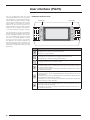
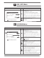
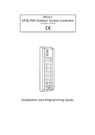
Quick
Reference
AIR / WATER H
Heatt pump
USER MANUAL
pCO
5
GB
4472010_02 - 1405
Index
User interface (PGD1) .................................................................................................................... 4
Start-up procedure ......................................................................................................................... 5
Menu structure and navigation ..................................................................................................... 6
User operating procedures............................................................................................................ 7
Main menu ....................................................................................................................................... 8
Main menu - General monitoring ..................................................................................................................................... 8
Main menu - System monitoring ...................................................................................................................................... 9
Main menu - Circuit 1 monitoring .................................................................................................................................... 9
Main menu - Circuit 2 monitoring (visible if present)..................................................................................................... 10
Main menu - General circuits monitoring ...................................................................................................................... 10
In / Out Menu ................................................................................................................................. 11
In / Out Menu - External temperature monitoring .......................................................................................................... 11
In / Out Menu - Fans monitoring (common or circuit 1) ................................................................................................ 11
In / Out Menu - Defrost monitoring circuit 1 / circuit 2 .................................................................................................. 12
In / Out Menu - Analogue input monitoring (1) .............................................................................................................. 13
In / Out Menu - Analogue input monitoring (2) .............................................................................................................. 13
In / Out Menu - Analogue input monitoring (3) .............................................................................................................. 13
In / Out Menu - Analogue input monitoring (4) (only on units with two circuits)............................................................ 14
In / Out Menu - Analogue input monitoring (5) (only on units with two circuits)............................................................ 14
In / Out Menu - Digital input monitoring (1) ................................................................................................................... 14
In / Out Menu - Digital input monitoring (2) ................................................................................................................... 15
In / Out Menu - Digital input monitoring (3) ................................................................................................................... 15
In / Out Menu - Digital input monitoring (4) ................................................................................................................... 15
In / Out Menu - Digital input monitoring (5) ................................................................................................................... 16
In / Out Menu - Digital input monitoring (6) ................................................................................................................... 16
In / Out Menu - Digital output monitoring (1) ................................................................................................................. 17
In / Out Menu - Digital output monitoring (2) ................................................................................................................. 17
In / Out Menu - Digital output monitoring (3) ................................................................................................................. 17
In / Out Menu - Digital output monitoring (4) ................................................................................................................. 18
In / Out Menu - Digital output monitoring (5) ................................................................................................................. 18
In / Out Menu - Digital output monitoring (6) ................................................................................................................. 18
ON / OFF Menu ............................................................................................................................. 19
ON / OFF Menu - Switching unit on or off...................................................................................................................... 19
SYSTEM Menu .............................................................................................................................. 19
SYSTEM Menu - Selecting the operating mode ............................................................................................................ 19
SYSTEM Menu - Setting main setpoints ........................................................................................................................ 20
SYSTEM Menu - Setting secondary setpoints............................................................................................................... 20
SYSTEM Menu - Time-clock settings (A) and (B) ......................................................................................................... 21
SYSTEM Menu - Time-clock settings (C) and (D) ......................................................................................................... 21
SYSTEM Menu - Copy time-clock settings function ...................................................................................................... 22
SYSTEM Menu - Setting change-over based on external temperature ........................................................................ 22
SYSTEM Menu - Setting change-over based on calender ........................................................................................... 23
INSTALLER Menu (Password 0000) ............................................................................................ 23
INSTALLER Menu- Insert password to access menus.................................................................................................. 23
INSTALLER Menu- Enabling digital inputs ID3 and ID4................................................................................................ 24
INSTALLER Menu- Addressing BMS supervisor system .............................................................................................. 24
INSTALLER Menu- Enabling primary functions by BMS ............................................................................................... 24
INSTALLER Menu- Addressing secondary supervisor system (not opto-isolated)....................................................... 25
INSTALLER Menu- Selecting control for water production............................................................................................ 25
INSTALLER Menu- Setting parameters for cooling control ........................................................................................... 25
INSTALLER Menu- Setting parameters for heating control ........................................................................................... 26
INSTALLER Menu- Setting ambient curve parameters for cooling ............................................................................... 26
INSTALLER Menu- Setting ambient curve parameters for heating ............................................................................... 26
INSTALLER Menu- Configuring pumps ......................................................................................................................... 27
INSTALLER Menu- Setting pump anti-freeze function .................................................................................................. 27
INSTALLER Menu- Setting fans anti-icing function ....................................................................................................... 27
INSTALLER Menu- Setting pump operation during use of anti-freeze heaters ............................................................. 28
INSTALLER Menu- Setting multi-function input ............................................................................................................. 28
INSTALLER Menu- Configuration of capacity limit from multi-function input (if enabled) ............................................. 28
INSTALLER Menu- Configuration of variable setpoint from multi-function input (if enabled) ....................................... 29
INSTALLER Menu- Configuration of variable setpoint from multi-function input (if enabled) ....................................... 29
INSTALLER Menu- Configuration of NTC signal from multi-function input (if enabled) ................................................ 29
INSTALLER Menu- Monitoring compressor hour counter circuit 1................................................................................ 29
INSTALLER Menu - Operation Silent Night Set ............................................................................................................. 30
INSTALLER Menu - Management of electrical heaters ................................................................................................. 30
INSTALLER Menu - Enabling boiler............................................................................................................................... 30
INSTALLER Menu - Set temperature of integration and substitution ............................................................................ 30
INSTALLER Menu- Monitoring compressor hour counter circuit 2 (if present) ............................................................. 31
INSTALLER Menu- Monitoring number of compressor starts circuit 1 .......................................................................... 31
INSTALLER Menu- Monitoring number of compressor starts circuit 2 (if present) ....................................................... 31
INSTALLER Menu- Monitoring pump operating hours .................................................................................................. 31
INSTALLER Menu- Monitoring unit configurator and test info ....................................................................................... 32
INSTALLER Menu- Monitoring unit configurator and test info ....................................................................................... 32
CLOCK Menu ................................................................................................................................ 32
CLOCK Menu - Setting system date and time .............................................................................................................. 32
CLOCK Menu - Setting automatic time change (summer/winter time) ......................................................................... 33
CLOCK Menu - Setting holidays ................................................................................................................................... 33
Alarm summary table ................................................................................................................... 34
Alarm history and memory .......................................................................................................... 37
Alarm history ................................................................................................................................ 37
Quick reference ............................................................................................................................ 40
User interface (PGD1)
The unit control panel allow the quick
setting and display of the unit’s operating parameters. The board memorises
all the default settings and any modifications. By installing the remote control
panel PGD1 it is possible to remotely
replicate all the functions and the settings available on the unit. After a power
failure the unit is capable of an automatic restart, retaining the original settings.
INTERFACE CONTROL KEYS:
Control keys
The user interface consists of a graphic
display with six navigation keys; the display is arranged through a menu hierarchy, activated by pressing the navigation keys. The default display of these
menus is the main screen. The navigation between the various parameters is
by using the arrow keys located to the
right of the display. These keys are also
used for the modification of the selected
parameter.
Control keys
Prg
Esc
Key
Function
ALARM key
Displays the list of active and historical alarms
(red LED on = active alarm)
Prg
MENU ACTIVATION key
• Pressing this key activates the navigation between menus
(orange LED on = winter operating mode active)
Esc
EXIT MENU key
• Pressing this key returns to the previous menu
NAVIGATION (+) key
• Pressing this key when navigating between menu/parameters passes to
the next menu/parameter
• Pressing this key when modifying a parameter increases the value of
the selected parameter
NAVIGATION (enter) key
• Pressing this key when navigating between menus allows entry to the
selected menu
• Pressing this key when navigating between parameters allows selection
of the parameter displayed to modify it
• Pressing the key when modifying a parameter confirms the modification
of the parameter value selected
NAVIGATION (-) key
• Pressing this key when navigating between menu/parameters passes to
the previous menu/parameter
• Pressing this key when modifying a parameter decreases the value of
the selected parameter
4
Start-up procedure
After having powered up the unit the control
board will carry out preliminary operations
before being ready for use. This initial procedure takes around 60 seconds to complete. During the initial loading procedure
two screens are displayed: a start-up screen
and a screen to select the system language.
These screens are detailed in the table below.
WARNING: The system language can be
set on the screen displayed at the startup or can be modified at any time through
the appropriate screen contained in the
Installer menu.
Start-up procedure
Display on the unit
Wait please
6s
Index
Display/Parameter
A
Remaining time for software loading: this value shows the
remaining time to starting the software loaded on the unit,
and passing the to system language selection
B
System language: this parameter shows the current language set for the system. To change the language follow
the instructions shown on the screen.
Remaining time to select the language: this value shows
the remaining time to modify the language. When the time
elapses the display goes to the main screen (Main screen General monitoring).
A
WARNING: It is possible to modify the system language at
any time using the appropriate screen contained in the
Installer menu. (Menu password = 0000).
Installer
Language:
B
ENGLISH
C
Pussh ENTER for change
ESC to confirm
Time show mask:
20
C
5
Menu structure and navigation
Both the functions to control the unit and the operating information are displayed on the unit mounted control panel.
All the functions and information are arranged in screens
which in turn are grouped into menus.
The operating menus are arranged as in the following drawing:
A
During the normal operation of the unit the main screen is
displayed, from which it is possible to access the selection of the other operating menus.
The menus are displayed through the rotation of the icons
that they represent. Once the desired icon is selected the
chosen menu is entered, permitting the display or modification of the parameters that it is made up from. The
procedure for navigating the menus, or changing parameters, is explained in detail in the chapter “User operating
procedures”.
B
The adjacent drawing shows the relation between the various menus and the navigation keys used.
I
C
H
D
! WARNING: Improper selection of the parameters in the
Installer menu may cause malfunctions of the unit. It is
recommended that these parameters are only modified
by personnel qualified in the installation and configuration of the unit.
G
E
F
Index
Icon
Menu
Menu function
A
---
MAIN
The screens in this menu display the current conditions of the unit (unit status, setpoints,circuit data, etc.)
6
B
IN/OUT
C
ON/OFF
This menu permits the unit to be enabled or disabled, and provides information on the status
D
SYSTEM
This menu permits the selection of the operating modes, the water setpoints and the time-clock for the
system
E
RECOVERY
If the unit includes heat recovery, this menu permits the setting of the parameters associated with the
heat recovery
F
INSTALLER
This menu contains the settings useful for the installer (enabling digital inputs, BMS configuration, control,
pumps, etc.)
WARNING: This menu is password protected. The password is: 0000
G
ASSISTANCE
This menu is only accessible to qualified personnel
H
FACTORY
This menu is only accessible to qualified personnel
I
CLOCK
This menu contains advanced information on the unit operation
This menu contains the clock settings for the system control (date, hour, calender)
! User operating procedures
To check or modify the operating parameters of the unit it is necessary to use the interface of the control panel on the unit. The basic operations
that the user must be capable of, for the correct use of the unit, are:
(1) Moving from one menu to the next.
(2) Selecting and modifying a parameter.
In this manual the parameters that can be modified by the user are identified by the icon (
).
2
1
Moving between menus
Selecting and modifying a menu
(a) To move between the menus, the order in
which they are displayed is shown in the previous
page, enter the menu selection mode by pressing
(a) Once in the menu selected, by following the
procedure ( 1 ), it is possible to move between
the screens using the arrow keys: the key ( ) to
move to the previous parameter, and the key ( )
to move to the next parameter.
the key (
Prg
).
previous
parameter
(b) Once in the menu selection mode it is possible
to move between menus using the arrow keys: the
key ( ) to move to the previous menu, and the
key ( ) to move to the next menu.
next
parameter
(c) When the desired parameter is seen press
the key ( ) to enter the parameter. To exit the
parameter and return to the parameter selection
mode press the key ( ).
WARNING: Once a parameter is selected by
pressing the key ( ), the parameter selection
mode is automatically accessed and in this mode
the desired parameter values can be set with the
following procedure:
(1) Pressing the key ( ) causes a flashing cursor to
appear on the first modifiable field of the parameter. If no modifiable fields are displayed then the
cursor will not appear.
(2) Pressing the key ( ) or the key ( ), the value
of the field can be increased or decreased.
(3) Pressing the key ( ) confirms the modification of the field value, saving it in memory. On the
basis of the type of parameter selected the number of modifiable fields can change.
Esc
previous
menu
next
menu
(c) When the desired menu is seen press the key (
)to enter the menu. Press the key( ) to return to
the menu selection mode.
Esc
entering a
menu
exiting a
menu
entering a
parameter
exiting a
parameter
7
Main menu
During normal operation the first screen of
the Main menu is displayed on the unit. This
menu consists of several screens with different information on the operating status of
the system which can be navigated using
the arrow keys. In these screens the information is read only and no parameters can be
changed.
WARNING: If no keys are pressed for at
least 5 minutes during the use of the control panel the software automatically return to the main screen of this menu.
Main menu - General monitoring
Display on the unit
L
I
Aermec
A
D
CN
C1 37%
MIX 49%
C2 49%
14.9OC
C
Display/Parameter
A
System supply water temperature: shows the water temperature leaving the heat exchanger
B
System return water temperature: shows the water temperature entering the heat exchanger
C
Pump active: the icon appears if the unit pump operates,
if the unit is supplied with a pump. The number next to the
pump indicates which of the pumps is active
D
Compressor status circuit 1: the icon shows the current status of the compressors present in circuit 1, which can be:
• On ( )
• Off ( )
• Disabled ( )
• In alarm ( )
• Part load operation lasting 10 minutes (P)
E
Compressor status circuit 2: the icon shows the current status of the compressors present in circuit 2, which are the
same as those available on circuit 1
F
Fan speed circuit 1: the value shows the percentage speed
of the fans on circuit 1
G
Common fan speed: the value shows the percentage
speed of the common fans between two circuits
H
Fan speed circuit 2: the value shows the percentage speed
of the fans on circuit 2
I
System capacity demand: this element presents the system
capacity demand as a bar graphic between 0 and 10
WARNING: Based on the operating mode of either heating
or cooling the heat exchanger changes role. This is shown
on the display of the screen by EV = evaporator, CN = condenser
Thu 10:59
14.3OC
EV
B
Index
F
G
H
1
C1:
C2:
E
! WARNING: Several icons can appear in this
screen to show specific states of the system, and
the icons can be:
( LT ) ) low leaving temperature anti-freeze function is
active (compressors switched off)
( HT ) high leaving water temperature prevention is
active (compressors switched off)
( LC ) low load function active
( ) anti-freeze heater active (set point: 4.0°C - differential: 1.0K)
( ) the return water temperature is dropping so new
requests for cooling load are disabled
Date and time: shows the current date and time
( ) the return water temperature is rising so new requests for heating load as disabled
L
( F ) the flow switch is open so compressors will be
switched off whilst the pump attempts to enable the
flow switch
8
Main menu - System monitoring
Display on the unit
A
Index
A
Current setpoint: shows the current system setpoint
B
Operating mode: the icon shows the current operating
mode of the system ( = cooling,
= heating)
C
Differential: shows the current system working differential
D
Control sensor: these values show the sensor on which the
control is based (inlet or outlet), and the current value read
by the selected sensor
E
Proportional error: if the Proportional + Integral function is
active, this shows the proportional value
F
Integral error: if the Proportional + Integral function is active,
this shows the integral value
G
Load request: shows the percentage load required by the
system
H
Capacity output: shows the percentage output to the system
B
Plant
Setpoint
7.0 C
o
C
Diff. 5.0oC
Outlet Temp.:
Ep
30.0%
Ei
Req.
39%
Act.:
E
G
8.5oC
9.0%
29%
D
F
H
! WARNING: Several icons can appear in this
screen to show specific states of the system, and
the icons can be:
(
OFF
(
M
Display/Parameter
) time-clock is active
) multi-function input is active
( LC ) low load function is active
Main menu - Circuit 1 monitoring
Display on the unit
Index
A
High pressure: shows the discharge pressure of the circuit
B
Low pressure: shows the suction pressure of the circuit
C
Condensing temperature: shows the condensing temperature
D
Evaporating temperature: shows the evaporating temperature
E
Liquid temperature: shows the liquid temperature (displayed
only for heat pumps models)
F
Discharge temperature: shows the discharge temperature
G
Compressor status: the icon represents the compressor
status of the circuit. Each compressor is numbered with the
code CP, and for each the current status is shown, being:
• On ( )
• Off ( )
H
Minimum residual time: the value shows how many seconds
remain until minimum required On or Off time elapses for the
current status of each compressor
Circuit 1
A
AP: 23.1bar -> Tc: 39.5oC
C
B
BP:
6.4bar -> Te: -2.6oC
D
14.8oC
80.8oC
E
Liquid T.
Disc.Temp.:
G
CP1:
CP2:
0s
0s
F
H
Display/Parameter
9
Main menu - Circuit 2 monitoring (visible if present)
Display on the unit
Index
A
High pressure: shows the discharge pressure of the circuit
B
Low pressure: shows the suction pressure of the circuit
C
Condensing temperature: shows the condensing temperature
D
Evaporating temperature: shows the evaporating temperature
E
Liquid temperature: shows the liquid temperature
F
Discharge temperature: shows the discharge temperature
(displayed only for heat pumps models or unit with total
heat recovery)
G
Compressor status: the icon represents the compressor
status of the circuit. Each compressor is numbered with the
code CP, and for each the current status is shown, being:
• On ( )
• Off ( )
H
Minimum residual time: the value shows how many seconds
remain until minimum required On or Off time elapses for the
current status of each compressor
Circuit 2
A
AP: 23.1bar -> Tc: 39.5oC
C
B
BP:
6.4bar -> Te: -2.6oC
D
14.8 C
80.8oC
E
T.Liquid:
Disc.Temp.:
G
o
F
H
0s
0s
CP1:
CP2:
Display/Parameter
Main menu - General circuits monitoring
Display on the unit
Circuits
A
Total require
B
Circuit 1:
Circuit 2:
C
100%
Display/Parameter
A
Total capacity request: shows the current value of total
capacity request from the system
B
Capacity output of circuit 1: shows the current capacity output of the circuit to satisfy the system request
C
Capacity output of circuit 2: shows the current capacity output of the circuit to satisfy the system request
46%
54%
Time between starts:
10
Index
Residual time to next compressor: shows the remaining time
before the next compressor is turned on, if required
D
0s
D
In / Out Menu
In / Out Menu - External temperature monitoring
Display on the unit
Outdoor temp.
8.2oC
8.2oC
6.0oC
Today
Yester
B
A
10.2oC
8.3oC
Index
Display/Parameter
A
External air temperature: shows the current external air temperature
B
External air temperature (minimum today): shows the minimum external air temperature read today
C
External air temperature (maximum today): shows the maximum external air temperature read today
D
External air temperature (minimum yesterday): shows the
minimum external air temperature read yesterday
External air temperature (maximum yesterday): shows the
maximum external air temperature read yesterday
C
E
E
D
In / Out Menu - Fans monitoring (common or circuit 1)
Display on the unit
Index
Display/Parameter
A
Circuit fans: shows which circuit the data refers to, with
options of:
• Fans: shows that the fans are common to both circuits
• Fans 1: data refer to the fans of circuit 1
• Fans 2: data refers to the fans of circuit 2
B
B
Fan speed: shows the percentage speed at which the fans
are operating (common, circuit 1 or circuit 2)
C
D
C
Fan setpoint: shows the current fans setpoint
F
D
Differential on fan setpoint: shows the current differential
applied on the fan setpoint
! WARNING: The information contained in this
E
• COMMON control: The fans of both circuits are controlled together, in which case there will be only one
screen which summarises the data relating to the
fans (as seen in the screen above).
Fan status circuit 1: shows the current status of the fans, which
can be:
• OFF: fans off
• PRE-VENTILATION: fans on in anticipation of compressor
• HIGH PRESSURE: control based on high pressure
• POST-VENTILATION: fans on after compressors switch off
• ANTI-ICING: fans on phase to prevent ice accumulation
• DEFROST: defrost phase
• LOW PRESSURE: control based on low pressure
• MAXIMUM SPEED: fans at maximum speed
• SILENCED: speed reduction to reduce noise levels
F
Fan pressure circuit 1: shows the current pressure value read
G
Fan status circuit 2: equivalent values to that of item (E) and
this value is only displayed if the fans are common to the
two circuits. If not, this value is not displayed but is shown in
the following screen “Fans circuit 2”
A
Fan 1
Speed
100%
E
Set:
Diff:
1:Off.
2:Off.
G
0.0bar
0.0bar
23.1bar
22.0bar
H
screen can be split into two screens of “Fans circuit 1” and “Fans circuit 2”. The control types can
be:
• INDIVIDUAL control: The fans of circuit 1 and
circuit 2 are controlled independently, so the system will display two distinctive screens to display
the data of the two circuits. In this case the two
screens will be successively displayed and will
contain the same type of data, except for points (E)
and (G) in that (E) is displayed only in the screen
“Fans circuit 1”, whilst (G) is displayed only in the
screen “Fans circuit 2”.
H
Fan pressure circuit 2: shows the current pressure value
read and is only displayed if the fans are common to both
circuits. If not, this value is not displayed but is shown in the
following screen “Fans circuit 2”.
11
In / Out Menu - Defrost monitoring circuit 1 / circuit 2
Display on the unit
A
Defrost
B
Disabled
High outdoor temp.
C
0s
D
0.0
F
14.8 C
G
Times:
E
LP aver: 6.4bar
Liquid.Temp.:
DP:
o
Index
Display/Parameter
A
Defrost circuit: shows which circuit the values refer to, if a
second circuit is present, and provides a second screen for
the second circuit:
• Defrost C1: data relating to circuit 1
• Defrost C2: data relating to circuit 2
B
Defrost information: provides status information on the
defrost, which can be:
• DISABLED: defrost disabled
• BYPASS: bypass phase after the compressor start
• DECREASING CALCULATION: phase calculating the
decrease of pressure
• AWAITING CYCLE INVERSION: system in pause before
cycle inversion
• START DEFROST: defrost in start phase
• DEFROSTING: defrost cycle
• END DEFROST: end of the defrost cycle
• FIRST DEFROST: shows the first defrost phase after a power
loss
C
Additional defrost information: provides additional status
information on the defrost:
• HIGH EXTERNAL AIR TEMPERATURE: the external air temperature is above the level for enabling defrost
• CIRCUIT OFF: all the compressors of the circuit are off;
defrost is disabled
• LP ABOVE LIMIT: the low pressure is above the level to
enable defrost
• MINIMUM TIME BETWEEN DEFROST: defrost is disabled during the period of minimum time between defrosts
• START CP: compressor just started; await the bypass time
before calculating the pressure decrease
• NEW LP REFERENCE: a new low pressure value has been
taken as reference for the calculation of decreasing pressure;
• START FOR LP LIMIT: start of defrost to overcome the low
pressure limit
• START FOR DELTA P: start of defrost to overcome the
decreasing value of low pressure
• TEMP. LIQUID OK: the liquid temperature has overcome
the limit to define the end of defrost
• MINIMUM DEFROST TIME: defrost continuous until the minimum time is exceeded even if the exit conditions are met
• AWAITING OTHER CIRCUIT: occurs if the fans are common
to both circuits and the first circuit to finish defrost awaits the
second circuit to finish
• BYPASS FIRST START: the first defrost after a power loss can
only occur after the compressor has run for the determined
time
• LIQUID TEMP. LOW: liquid temperature below the level that
determines the end of defrost
• START FOR DGT: defrost is activated due to the level of the
discharge gas temperature exceeding the limit
• FORCED: in the case the fans are common to both circuits
this circuit has been forced into defrost due to defrost of the
other circuit, even if not required
D
Defrost time: the value can indicate the maximum time
before completing defrost (in the event the normal levels
for completion have not been met), or the minimum defrost
cycle time (in the event the “TEMP. LIQUID OK” message is
displayed), to exit defrost
E
Low average pressure: shows the average low pressure in
the last minute
F
Delta pressure: shows the accumulated delta pressure to
determine activation of defrost
G
Liquid temperature: shows the liquid temperature to determine exit of the defrost cycle
! WARNING: in the case the unit has two circuits
this screen is repeated and the heading of (A)
changed to C2, and each screen will provide data
for the relevant circuit.
12
In / Out Menu - Analogue input monitoring (1)
Display on the unit
Inputs
pCO5
U1 = Inlet Temp.water
evap.:
14.9oC
U2 = Output Temp.water
evap.:
18.0oC
U3 = Ext.Temp:
17.9oC
Index
Display/Parameter
A
Analogue input U1: shows the heat exchanger inlet water
temperature
B
Analogue input U2: shows the heat exchanger outlet temperature
Analogue input U3: shows the external air temperature
A
B
C
C
In / Out Menu - Analogue input monitoring (2)
Display on the unit
Index
Display/Parameter
Analogue input U4: shows the discharge gas temperature of
circuit 1
Inputs
pCO5
A
U4 = Liquid Temp.
circuit 1:
15.3oC
A
In / Out Menu - Analogue input monitoring (3)
Display on the unit
Inputs
A
C
pCO5
U5 = High press.circ.1:
0.0bar
59.3oC
U6 = Low press.circ.1:
0.0bar
-28.5oC
B
Index
Display/Parameter
A
Analogue input U5: shows the high pressure transducer
value read for circuit 1
B
Conversion HP temperature: this is the conversion value into
temperature from the pressure read by the high pressure
transducer of circuit 1
C
Analogue input U6: shows the low pressure transducer value
read for circuit 1
Conversion LP temperature: this is the conversion value into
temperature from the pressure read by the low pressure
transducer for circuit 1
D
D
13
In / Out Menu - Analogue input monitoring (4) (only on units with two circuits)
Display on the unit
Index
Display/Parameter
Analogue input U7: shows the discharge gas temperature of
circuit 2
Ingressi
pCO5
A
U7 = Liquid temp.
circuit 2:
15.3oC
A
In / Out Menu - Analogue input monitoring (5) (only on units with two circuits)
Display on the unit
Inputs
A
C
pCO5
U8 = High press.circ.2:
0.0bar
59.3oC
U9 = Low press.circ.2:
0.0bar
-28.5oC
B
Index
Display/Parameter
A
Analogue input U8: shows the high pressure transducer
value read for circuit 2
B
Conversion HP temperature: this is the conversion value into
temperature from the pressure read by the high pressure
transducer of circuit 2
C
Analogue input U9: shows the low pressure transducer value
read for circuit 2
Conversion LP temperature: this is the conversion value into
temperature from the pressure read by the low pressure
transducer for circuit 2
D
D
In / Out Menu - Digital input monitoring (1)
Display on the unit
Index
Display/Parameter
A
Digital input ID1: shows the binary status of the input read
from the flow switch of the evaporator, which are:
• OPEN: flow switch alarm
• CLOSED: normal operation
B
Digital input ID2: shows the binary status of the input read
from the high pressure pressostat of circuit 1, which are:
• OPEN: high pressure pressostat alarm
• CLOSED: normal operation
Inputs
pCO5
ID1: Flow switch
Close
ID2: High press.circ.1
Close
ID3: Fan Overload 1
Close
14
A
B
C
C
Digital input ID3: shows the binary status of the input relating
to the circuit breaker of the fans on circuit 1, which can be:
• OPEN: circuit breaker alarm
• CLOSED: normal operation
In / Out Menu - Digital input monitoring (2)
Display on the unit
Index
Display/Parameter
A
Digital input ID4: shows the binary status read from the input
of the phase control device, which can be:
• OPEN: phase control device in alarm
• CLOSED: normal operation
B
Digital input ID5: shows the binary status of the input relating to the circuit breaker of compressor 1 on circuit 1, which
can be:
• OPEN: circuit breaker alarm
• CLOSED: normal operation
C
Digital input ID6: shows the binary status of the input relating to the circuit breaker of compressor 2 on circuit 1, which
can be:
• OPEN: circuit breaker alarm
• CLOSED: normal operation
Inputs
pCO5
ID4: All.Phase Monitor
Close
ID5: Overl.comp1 circ1
Close
ID6: Overl.comp2 circ1
Close
A
B
C
In / Out Menu - Digital input monitoring (3)
Display on the unit
Index
Display/Parameter
A
Digital input ID7: shows the binary status of the input relating to the circuit breaker of compressor 3 on circuit 1, which
can be:
• OPEN: circuit breaker alarm
• CLOSED: normal operation
B
Digital input ID8: shows the binary status of the input read
from the high pressure pressostat of circuit 2 (if provided),
which are:
• OPEN: high pressure pressostat in alarm
• CLOSED: normal operation
C
Digital input ID9: shows the binary status of the input relating
to the circuit breaker of the fans on circuit 2 (if provided),
which can be:
• OPEN: circuit breaker alarm
• CLOSED: normal operation
Inputs
pCO5
ID7: Overl.comp2 circ1
Close
ID8: High press.circ.2
Close
ID9: Fan Overload 2
Close
A
B
C
In / Out Menu - Digital input monitoring (4)
Display on the unit
Inputs
pCO5
ID10:2nd Set enable
Open
ID11:Overl.comp1 circ2
Close
ID12:Overl.comp2 circ2
Close
Index
Display/Parameter
A
Digital input ID10: shows the binary status of the input relating to the secondary setpoint function, which are:
• OPEN: secondary setpoint not active
• CLOSED: secondary setpoint active
NOTE: To control this function the installer must use the digital input ID10 and provide a volt free contact for the activation of the secondary setpoint
B
Digital input ID8: shows the binary status of the input relating to the circuit breaker of compressor 1 on circuit 2, which
can be:
• OPEN: circuit breaker alarm
• CLOSED: normal operation
C
Digital input ID9: shows the binary status of the input relating to the circuit breaker of compressor 2 on circuit 2, which
can be:
• OPEN: circuit breaker alarm
• CLOSED: normal operation
A
B
C
15
In / Out Menu - Digital input monitoring (5)
Display on the unit
Index
Display/Parameter
A
Digital input ID13: shows the binary status of the input relating to the circuit breaker of compressor 3 on circuit 2, which
can be:
• OPEN: circuit breaker alarm
• CLOSED: normal operation
B
Digital input ID14: shows the binary status of the input relating to the circuit breaker of pump 1, which can be:
• OPEN: circuit breaker alarm
• CLOSED: normal operation
C
Digital input ID15: shows the binary status of the input relating to the circuit breaker of pump 2 (visible if present), which
can be:
• OPEN: circuit breaker alarm
• CLOSED: normal operation
Inputs
pCO5
ID13:Overl.cmp.3 circ.2
Open
ID14:Overl. pump1 plant
Open
ID15:Overl. pump2 plant
Close
A
B
C
In / Out Menu - Digital input monitoring (6)
Display on the unit
Inputs
pCO5
ID16:Remote Cool/Heat
Open
ID17:Remote On/Off
Open
ID18:Multifunct Eanble
Open
16
Index
Display/Parameter
A
Digital input ID16: shows the binary status of the input relating to the change of season function, which can be:
• OPEN: remote season change not active
• CLOSED: remote season change active
NOTE: To control this function the installer must use the digital input ID16 and provide a volt free contact for the activation of the remote season changeover
B
Digital input ID17: shows the binary status of the input relating to the remote ON/OFF function, which can be:
• OPEN: remote ON/OFF remote not active
• CLOSED: remote ON/OFF active
NOTE: To control this function the installer must use the digital input ID17 and provide a volt free contact for the activation of the remote ON/OFF
C
Digital input ID18: shows the binary status of the input relating to the multi-function U10 (this function is detailed in the
Installer menu), which can be:
• OPEN: multi-function contact not enabled
• CLOSED: multi-function contact enabled
NOTE: To control this function the installer must use the digital input ID18 and provide a volt free contact for the activation of the multi-function
A
B
C
In / Out Menu - Digital output monitoring (1)
Display on the unit
Index
Display/Parameter
A
Digital output NO1: shows the binary status of the output
relating to pump 1, which can be:
• OPEN: pump 1 not active
• CLOSED: pump 1 active
B
Digital output NO2: shows the binary status of the output
relating to compressor 1 of circuit 1, which can be:
• OPEN: compressor not active
• CLOSED: compressor active
Output
pCO5
NO1: Pump 1
Close
A
Close
B
Close
C
NO2: Comp.1 circ.1
NO3: Comp.2 circ.1
C
Digital output NO3: shows the binary status of the output
relating to compressor 2 of circuit 1, which can be:
• OPEN: compressor not active
• CLOSED: compressor active
In / Out Menu - Digital output monitoring (2)
Display on the unit
Index
Display/Parameter
A
Digital output NO4: shows the binary status of the output
relating to compressor 3 of circuit 1, which can be:
• OPEN: compressor not active
• CLOSED: compressor active
B
Digital output NO5: shows the binary status of the output to
the liquid solenoid valve of circuit 1, which can be:
• OPEN: valve not active
• CLOSED: valve active
C
Digital output NO6: shows the binary status of the output to
the reversing valve of circuit 1 (in heat pump models), which
can be:
• OPEN: valve not active
• CLOSED: valve active
Output
pCO5
NO4: Comp.3 circ.1
Open
A
Open
B
Open
C
NO5: VSL circuit 1
NO6: VIC circuit 1
In / Out Menu - Digital output monitoring (3)
Display on the unit
Index
Display/Parameter
A
Digital output NO7: shows the binary status of the output to
the fans of circuit 1, which can be:
• OPEN: fans not active;
• CLOSED: fans active
B
Digital output NO8: shows the binary status of the output
generated by a serious alarm, which can be:
• OPEN: no alarm present
• CLOSED: alarm present
C
Digital output NO9: shows the binary status of the output
relating to compressor 1 of circuit 2 (visible if present), which
can be:
• OPEN: compressor not active
• CLOSED: compressor active
Output
pCO5
NO7: Fan 1
Open
A
Open
B
Open
C
NO8: Serious alarm
NO9: Comp.1 circ.2
17
In / Out Menu - Digital output monitoring (4)
Display on the unit
Index
Display/Parameter
A
Digital output NO10: shows the binary status of the output
relating to compressor 2 of circuit 2 (visible if present), which
can be:
• OPEN: compressor not active
• CLOSED: compressor active
B
Digital output NO11: shows the binary status of the output
relating to compressor 3 of circuit 2 (visible if present), which
can be:
• OPEN: compressor not active
• CLOSED: compressor active
C
Digital input NO12: shows the binary status of the output to
the liquid solenoid valve of circuit 2 (visible if present), which
can be:
• OPEN: valve not active
• CLOSED: valve active
Output
pCO5
NO10:Comp.2 circ.2
Open
A
Open
B
Open
C
NO11:Comp.3 circ.3
NO12:VSL Circuit 2
In / Out Menu - Digital output monitoring (5)
Display on the unit
Index
Display/Parameter
A
Digital output NO13: shows the binary status of the output to
the fans of circuit 2 (visible if present), which can be:
• OPEN: fans not active
• CLOSED: fans active
B
Digital output NO14: shows the binary status of the output to
the reversing valve of circuit 2 (visible if second circuit present in heat pump models), which can be:
• OPEN: valve not active
• CLOSED: valve active
C
Digital input NO15: shows the binary status of the output to
the bypass solenoid valve of circuit 1 (in heat pump models), which can be:
• OPEN: valve not active
• CLOSED: valve active
Output
pCO5
NO13:Fan 2
Open
A
Open
B
Open
C
NO14:VIC 2
NO15:VSBP1
In / Out Menu - Digital output monitoring (6)
Display on the unit
Index
Display/Parameter
A
Digital output NO16: shows the binary status of the output to
the bypass solenoid valve of circuit 2 (visible if second circuit
present in heat pump models), which can be:
• OPEN: valve not active
• CLOSED: valve active
B
Digital output NO17: shows the binary status of the output to
the anti-freeze heater, which can be:
• OPEN: heater not active
• CLOSED: heater active
Output
pCO5
NO16:VSBP2
Open
NO17:Antifreeze Heater
Open
NO18:Pump 2
Open
A
B
C
C
18
Digital input NO18: shows the binary status of the output
relating to pump 2 (visible if present), which can be:
• OPEN: pump 2 not active
• CLOSED: pump 2 active
ON / OFF Menu
ON / OFF Menu - Switching unit on or off
Display on the unit
Index
Display/Parameter
A
Current status: shows the current status of the unit:
• ENABLED: unit on
• OFF GENERAL: unit in standby
• OFF FOR ALARM: unit in standby due to an alarm
• OFF BY BMS: unit in standby, disabled by the BMS
• OFF BY CLOCK: unit in standby, disabled by time-clock
settings
• OFF BY DIG. IN: unit in standby, disabled by digital input
ID8
• OFF BY DISPLAY: unit in standby, disabled from the terminal
• ANTI-ICING: unit forced on to avoid icing
On/Off unit
Plant
A
Off general
General enable:
NO
B
B
User modifiable parameters
Switching unit on or off: by modifying this parameter it is possible to switch the unit on or off:
• YES: unit on
• NO: unit off
SYSTEM Menu
SYSTEM Menu - Selecting the operating mode
Display on the unit
Index
Display/Parameter
A
Current status: shows the current status of the unit:
• ENABLED: unit on
• OFF GENERAL: unit in standby
• OFF FOR ALARM: unit in standby due to an alarm
• OFF BY BMS: unit in standby, disabled by the BMS
• OFF BY CLOCK: unit in standby, disabled by time-clock
settings
• OFF BY DIG. IN: unit in standby, disabled by digital input
ID8
• OFF BY DISPLAY: unit in standby, disabled from the terminal
• ANTI-ICING: unit forced on to avoid icing
B
Active season: the symbol shows the current operating
mode:
• ( ): heating mode
• ( ): cooling mode
Plant
A
Off general
B
Switch On:
YES
C
Mode selection:
HEATING
D
User modifiable parameters
C
D
Unit enabled: shows if the unit is enabled for operation,
which can be:
• OFF: system not enabled for operation
• ON: system enabled for operation
• ON WITH SET2: system enabled for operation with secondary setpoint
• TIME-CLOCK: system enabled to operate under time-clock
programme
Selecting the operating mode: by modifying this parameter
it is possible to select the operating mode of the unit:
• COOLING: unit produces chilled water
• HEATING: unit unit produces hot water
• BY EXT. TEMP.: operating mode decided automatically by
the external air temperature
• BY DIG. IN: operating mode decided by digital input ID16
(input closed = heating)
• BY SUPERV.: operating mode decided by BMS
• BY CALENDAR: operating mode decided automatically
based on the season change-over date in the calender
19
SYSTEM Menu - Setting main setpoints
Display on the unit
Index
Display/Parameter
A
Main cooling setpoint: shows the operating setpoint used for
cooling mode
Plant
Main heating setpoint: shows the operating setpoint used for
heating mode
Setpoint 1
7.0oC
45.0oC
A
B
B
User modifiable parameters
SYSTEM Menu - Setting secondary setpoints
Display on the unit
Index
Display/Parameter
A
Secondary cooling setpoint: shows the secondary operating
setpoint for cooling mode
Plant
Heating secondary setpoint: shows the secondary operating
setpoint for heating mode
Setpoint 2
12.0oC
40.0oC
A
B
! WARNING: There are two possibilities for using
the secondary setpoint of the system:
• Enable the system with the secondary setpoint
as an option (ON CON SET 2) in the first screen of
the System menu.
• Use the digital input ID10, which activates the
secondary setpoint when closed.
User modifiable parameters
20
B
SYSTEM Menu - Time-clock settings (A) and (B)
Display on the unit
Index
Display/Parameter
A
Day to set: this shows the day for which the first two timeclock values (a) and (b) are programmed. This value can
be any day of the week or a HOLIDAY day
B
Time-clock start (a): shows the value of the start of the first
time-clock
C
Time-clock stop (a): shows the value of the stop of the first
time-clock
Plant
Timezone
Day
THURSDAY
B
E
a
b
ON
OFF
08:00
10:00
11:00
A
SEL
12:00
ON
D
OFF
G
F
C
D
! WARNING: All the screens for time-clock program-
Action associated with time-clock (a): shows the action carried out with the first time-clock, which can be:
• ON: unit enabled with main setpoint
• SET2: unit enabled with secondary setpoint
• OFF: unit in standby
ming are only visible if activated in the main screen
of the System menu (Enabling = TIME-CLOCK)
E
Time-clock start (b): shows the value of the start of the second time-clock
! WARNING: The values selected for the time-clock
F
Time-clock stop (b): shows the value of the stop of the second time-clock
(a) and (b) must follow logically:
B < C < E < F
NOTE: Outside of the four possible time-clock programmes the system will remain OFF
G
User modifiable parameters
Action associated with time-clock (b): shows the action carried out with the first time-clock, which can be:
• ON: unit enabled with main setpoint
• SET2: unit enabled with secondary setpoint
• OFF: unit in standby
SYSTEM Menu - Time-clock settings (C) and (D)
Display on the unit
Index
Display/Parameter
A
Day to set: this shows the day for which the last two timeclock values (c) and (d) are programmed. This value can
be any day of the week or a HOLIDAY day
B
Time-clock start (c): shows the value of the start of the third
time-clock
C
Time-clock stop (c): shows the value of the stop of the third
time-clock
Plant
Timezone
Day
THURSDAY
B
E
c
d
ON
OFF
13:00
15:00
16:00
A
SEL
20:00
C
ON
D
OFF
G
F
D
! WARNING: All the screens for time-clock program-
ming are only visible if activated in the main screen
of the System menu (Enabling = TIME-CLOCK)
! WARNING: The values selected for the time-clock
(a) and (b) must follow logically:
E
Time-clock start (d): shows the value of the start of the
fourth time-clock
F
Time-clock stop (d): shows the value of the stop of the
fourth time-clock
B < C < E < F
NOTE: Outside of the four possible time-clock programmes the system will remain OFF
G
User modifiable parameters
Action associated with time-clock (c): shows the action carried out with the first time-clock, which can be:
• ON: unit enabled with main setpoint
• SET2: unit enabled with secondary setpoint
• OFF: unit in standby
Action associated with time-clock (d): shows the action carried out with the first time-clock, which can be:
• ON: unit enabled with main setpoint
• SET2: unit enabled with secondary setpoint
• OFF: unit in standby
21
SYSTEM Menu - Copy time-clock settings function
Display on the unit
Index
Display/Parameter
A
Day to copy from: shows from which day the four time-clock
programmes are to be copied
B
Day to copy to: shows to which day to copy to the selected
settings. The time-clock from the reference day can be copied to an individual day of the week, to all remaining days
or only for holidays
Plant
Timezone
Day
A
THURSDAY
Copy to
---
No
C
Make copy: by changing this value to requested copy from
the reference day is made for the requested days
B
C
! WARNING: All the screens for time-clock program-
ming are only visible if activated in the main screen
of the System menu (Enabling = TIME-CLOCK)
User modifiable parameters
SYSTEM Menu - Setting change-over based on external temperature
Display on the unit
Index
Display/Parameter
A
Temperature level for cooling: shows the external air temperature value above which cooling mode is automatically
activated
Cooling/Heating
Temperature level for heating: shows the external air temperature value below which heating mode is automatically
activated
Select Cool/Heat with
Outdoor temperature
Set ON cooling
Set ON heating
23.0oC
18.0oC
A
B
B
! WARNING: This screen for automatic control
based on external air temperature is only visible if activated in the main screen of the System
menu (Selection mode = BY EXT. TEMP.)
User modifiable parameters
22
SYSTEM Menu - Setting change-over based on calender
Display on the unit
Index
Display/Parameter
A
Date to activate heating mode: shows the date after which
the change is made from cooling mode to heating mode
Cooling/Heating
Date to deactivate heating mode: shows the date after
which the change is made from heating mode to cooling
mode
Select Cool/Heat with
calendar
Start Heating
Finish Heating
01/OTT
01/MAG
A
B
B
! WARNING: This screen for automatic control
based on calender is only visible if activated in
the main screen of the System menu (Selection
mode = BY CALENDAR)
User modifiable parameters
INSTALLER Menu(Password 0000)
INSTALLER Menu- Insert password to access menus
Display on the unit
Index
Display/Parameter
Access password to menus: the password to be used to
access the Installer menus is the default value (0000)
Insert password
0000
A
A
User modifiable parameters
23
INSTALLER Menu- Enabling digital inputs ID3 and ID4
Display on the unit
Index
Display/Parameter
Enabling ID17: shows if the digital input ID3 is enabled for the
remote ON/OFF control function (ON = closed, OFF = open)
Input enable
ID17:On/Off plant:
N
A
A
User modifiable parameters
INSTALLER Menu- Addressing BMS supervisor system
Display on the unit
Index
A
Insatller
Supervisor BMS1
Protocol:
MODBUS
BaudRate:
19200 baud
Serial address:
1
A
B
B
Display/Parameter
Select protocol: shows which protocol is used to communicate with the BMS, with the supported protocols being:
• MODBUS: protocol Modbus/RS485
• CAREL: protocol by expansion
• pCOWEB: protocol by expansion pCOWEB
• LON: protocoll by expansion LON
Transmission speed: shows the speed of the serial communication
C
C
Address: shows the address assigned to which communication will be made with the BMS supervisor
User modifiable parameters
INSTALLER Menu- Enabling primary functions by BMS
Display on the unit
Index
Display/Parameter
A
Enable change-over by BMS: shows if the remote changeover by the BMS is enabled
Installer
Enable ON/OFF by BMS: shows if the remote starting and
stopping of the unit by the BMS is enabled
Supervisor:
Enable cooling/heating
by supervisor:
YES
A
Enable On-Off unit
by supervisor:
B
User modifiable parameters
24
B
YES
INSTALLER Menu- Addressing secondary supervisor system (not opto-isolated)
Display on the unit
Index
Display/Parameter
Address: shows the value of the address for the secondary
supervisor system for communications (this serial interface
is not opto-isolated so the connection distance permitted is
less than the main serial interface)
Installer
AerWeb300 BMS2
Address:
1
A
A
NOTE: The use of the second serial link is intended for transmission via the web (AerWeb300), although the serial link
can be to a second supervisor system in addition to the
main one (BMS1)
User modifiable parameters
INSTALLER Menu- Selecting control for water production
Display on the unit
Index
Installer
Regolation temperature
sensor with:
A
OUTPUT (U2)
A
Type reg.:
PROP + INT.
Integ.Time(Ki)
600s
B
Control sensor: shows which sensor the system bases the
control of water produced, which can be:
• OUTLET(U2): the sensor used to control the production of
water is that leaving the heat exchanger
• INLET(U1): the sensor used to control the production of
water is that entering the heat exchanger
• COMMON OUTLET SENSOR (U3 uPC): the sensor used to
control the production of water is the common leaving sensor in the event there are two heat exchangers
WARNING: Selecting the control based on the entering temperature means that the correct setting for the operating
setpoints must consider the addition or subtraction (based
on cooling or heating mode) of the differential temperature
to the operating setpoint
C
User modifiable parameters
Display/Parameter
B
Type of control: shows the logic used for the control, which
can be:
• PROP+INT: applies proportional and integral control
• PROP: applies proportional control only
C
Integral time: shows the integral time to add to the proportional control (in the event the type of control selection is
proportional and integral)
INSTALLER Menu- Setting parameters for cooling control
Display on the unit
Index
A
Installer
Cooling regolation
SETPOINT FIXED
Differential:
A
5.0oC
Display/Parameter
Type of setpoint: shows what type of logic is used for the
control of the operating setpoint, which can be:
• FIXED SETPOINT: the system will use as the operating setpoint the values set by the user in the System menu screen
(main and secondary setpoints)
• AMBIENT CURVE: the operating setpoint is calculated
automatically based on the selected ambient curve
Differential: shows the differential applied between the
water inlet and outlet, where such value depends on the
flow rate the system operates at
B
B
User modifiable parameters
25
INSTALLER Menu- Setting parameters for heating control
Display on the unit
Index
A
Installer
Heating regolation
SETPOINT FIXED
A
3.0oC
Differential:
Display/Parameter
Type of setpoint: shows what type of logic is used for the
control of the operating setpoint, which can be:
• FIXED SETPOINT: the system will use as the operating setpoint the values set by the user in the System menu screen
(main and secondary setpoints)
• AMBIENT CURVE: the operating setpoint is calculated
automatically based on the selected ambient curve
Differential: shows the differential applied between the
water inlet and outlet, where such value depends on the
flow rate the system operates at
B
B
User modifiable parameters
INSTALLER Menu- Setting ambient curve parameters for cooling
Display on the unit
Installer
Setpoint cool
Actual:
12.0oC
Compens. SET
max. 5.0oC 25.0oC
B
Display/Parameter
A
Actual setpoint: shows the current setpoint from the ambient
curve
B
Maximum differential on setpoint compensation: shows the
maximum change to apply to the original setpoint, when
reaching the external temperature specified at point (C)
C
Minimum external air temperature limit: shows the external
air temperature at which the maximum differential as specified at point (B) will be applied to the original setpoint
A
T.Ext
35.0oC
D
C
Index
D
Maximum external air temperature limit: shows the external
air temperature at which the original setpoint is applied.
Below this temperature the setpoint is proportionally
increased up to the value specified in point (C), where the
setpoint will be compensated by the maximum differential
specified in point (B)
User modifiable parameters
INSTALLER Menu- Setting ambient curve parameters for heating
Display on the unit
Installer
Setpoint heat
Actual:
45.0oC
Index
Display/Parameter
A
Actual setpoint: shows the current setpoint from the ambient
curve
B
Maximum differential on setpoint compensation: shows the
maximum change to apply to the original setpoint, when
reaching the external temperature specified at point (D)
A
SET
C
Compens.
max. 5.0oC
B
T.Ext
00.0 C
o
C
10.0oC
D
D
User modifiable parameters
26
Minimum external air temperature limit: shows the external
air temperature at which the original setpoint is applied.
Above this temperature the setpoint is proportionally
decreased up to the value specified in point (D), where the
setpoint will be compensated by the maximum differential
specified in point (B)
Maximum external air temperature limit: shows the external
air temperature at which the maximum differential as specified at point (B) will be applied to the original setpoint
INSTALLER Menu- Configuring pumps
Display on the unit
Index
Display/Parameter
A
Number of pumps: shows the number of pumps controlled
by the unit
WARNING: Modifying this parameter could result in the
pumps installed on the unit not being operated
Installer
Numbers of pumps:
Idle time:
2
A
8h
B
Inactivity time: shows the inactivity time for one pump after
which it will be activated (in the event that there are several
pumps avoids that they stand still for an excessive time)
B
User modifiable parameters
INSTALLER Menu- Setting pump anti-freeze function
Display on the unit
Index
Display/Parameter
A
Enabling anti-freeze function: shows whether to enable the
anti-freeze cycle function which activates the pump
B
Time cycle: shows the time interval between pump activations
C
Pump activation time: shows the time period that the pump
will be activated for the anti-freeze function
D
External air temperature limit: shows the temperature below
which the anti-freeze cycle is activated (if enabled)
Installer
Pump start cicles
Enable
N
Circle time:
30min
Pulse time:
2min
Min.Extern.Air Temp.:
5.0oC
A
B
C
D
User modifiable parameters
INSTALLER Menu- Setting fans anti-icing function
Display on the unit
Index
Display/Parameter
A
Enabling anti-icing function: shows whether to enable the
anti-icing function for the fans
B
External air temperature limit: shows the temperature below
which the anti-icing cycle is activated (if enabled)
C
Time off: shows the time interval between the periods of
activation for the fans during the anti-icing function
D
Fan activation time: shows the time period that the fans will
be activated for the anti-icing function
Fan
Fan antifreezer/snow
function enable:
Ext.Air temp.:
Pulse time off:
YES
A
1.0oC
B
120min
C
30s
D
Pulse time on:
User modifiable parameters
27
INSTALLER Menu- Setting pump operation during use of anti-freeze heaters
Display on the unit
Index
Display/Parameter
Pump enable: shows whether the pump is activated during
the operation of the electric anti-freeze heaters
Installer
Antifreeze Heater
Force ON pumps:
YES
A
A
User modifiable parameters
INSTALLER Menu- Setting multi-function input
Display on the unit
Index
Display/Parameter
A
Multi-function input: shows which function is assigned to the
multi-function input U10, which can be:
• NOT PRESENT: multi-function input disabled
• CAPACITY LIMIT: the input U10 is used to limit the capacity
of the unit in a manner proportional to the signal applied
at the input U10 (the configuration of the capacity range
controlled is available in the next screen, if this option is activated)
• VARIABLE SETPOINT: the input U10 is used to vary the operating setpoint in a manner proportional to the signal applied
at the input U10 (the configuration of the variation to the
setpoint range is available in the next screen, if this option is
activated)
Installer
Multifunction Input
Config. Input (U10)
VARIABLE SETPOINT
A
Type:
B
0-10V
WARNING: If the multi-function input is enabled then the status of the input to U10 will shown in the In/Out menu
User modifiable parameters
B
Type: shows the type of signal used for the multi-function
input, which can be:
• 0-10V: input signal 0-10V
• NTC: input signal NTC
• 4-20mA: input signal 4-20mA
INSTALLER Menu- Configuration of capacity limit from multi-function input (if enabled)
Display on the unit
Index
Display/Parameter
A
Minimum capacity limit: shows the minimum capacity limit
as a function of the input signal
Installer
Maximum capacity limit: shows the maximum capacity limit
as a function of the input signal
Input Multifunction
Power limit:
Minimun limit:
0%
A
Maximum limit:
100%
B
User modifiable parameters
28
B
INSTALLER Menu- Configuration of variable setpoint from multi-function input (if enabled)
Display on the unit
Index
Display/Parameter
A
Minimum cooling setpoint: shows the minimum setpoint as a
function of the input signal (on input U10)
B
Maximum heating setpoint: shows the maximum setpoint as
a function of the input signal (on input U10)
C
Minimum heating setpoint: shows the minimum setpoint as a
function of the input signal (on input U10)
D
Maximum heating setpoint: shows the maximum setpoint as
a function of the input signal (on input U10)
Installer
Ingresso
Input Multifunction
multifunzione
Setpoint
Variable variabile
SetPoint
in
Mode:
modo:
A
B
FREDDO
COOLING
Min:
7.0oC
Max: 11.0oC
CALDO
HEATING
Min: 45.0oC
Max: 50.0oC
C
D
User modifiable parameters
INSTALLER Menu- Configuration of NTC signal from multi-function input (if enabled)
Display on the unit
Index
Display/Parameter
A
Minimum NTC signal: Shows the minimum temperature
which corresponds to the to the minimum value for the
function selected to the multi-function input (capacity limitation or variable setpoint)
Installer
Maximum NTC signal: Shows the maximum temperature
which corresponds to the to the maximum value for the
function selected to the multi-function input (capacity limitation or variable setpoint)
Input Multifunction
Config. NTC
Minimun temp.:
7.0oC
A
Maximun temp.:
11.0oC
B
B
User modifiable parameters
INSTALLER Menu- Monitoring compressor hour counter circuit 1
Display on the unit
Index
A
Display/Parameter
Compressor 1 hour counter: shows the number of running
hours for compressor 1 on circuit 1
Hour meter
Circuit 1
Compressor 1:
Compressor 2:
Compressor 3:
0000h
0000h
---h
A
B
Compressor 2 hour counter: shows the number of running
hours for compressor 2 on circuit 1 (if present)
B
C
C
Compressor 3 hour counter: shows the number of running
hours for compressor 3 on circuit 1 (if present)
29
INSTALLER Menu - Operation Silent Night Set
Display on the unit
Index
Display/Parameter
A
Enable Silent Night operation: This value indicates whether
to enable night mode, this function enables operation
muted during the time period specified in the following
parameters
B
Start time slot night mode function: if the operation is muted
nocturnal active, this parameter indicates the time after
which this function will be activated
Fan
Control Silent night:
Control ON:
Control OFF:
NO
A
21:00
8:00
B
C
C
End time slot night mode function: if the operation is muted
nocturnal active, this parameter indicates the time after
which this function will be disabled
User modifiable parameters
INSTALLER Menu - Management of electrical heaters
Display on the unit
Index
Display/Parameter
A
Number electrical resistors installed: Indicates this value
if the number of electric heaters installed (minimum zero,
maximum three)
Installer
Additional resistances
number:
0
A
10%
B
Percentage of the power system: This value specifies the
percentage power of the individual resistance compared to
the total power of the unit;
Power resistance:
B
User modifiable parameters
WARNING: In order to allow proper management of electrical resistances in the system, all resistors must have the
same power, also please note that the maximum power of
the single resistor, managed by the system is equivalent to
50% of the rated power of the unit
INSTALLER Menu - Enabling boiler
Display on the unit
Index
Display/Parameter
Enable boiler replacement: This parameter specifies whether to enable the boiler when the outside temperature falls
below the value of “replacement” specified in the next window, or in the case where the heat pump is in “full alarm”
Installer
Boiler replacement
enabled:
NO
A
A
User modifiable parameters
INSTALLER Menu - Set temperature of integration and substitution
Display on the unit
Index
A
Installer
Air temp integration
5.0oC
Air temp replacement
-5.0oC
User modifiable parameters
30
A
B
B
Display/Parameter
Temperature integration: this value indicates the outdoor
temperature above which the heat pump function without
the aid of electrical resistors, while if the outside temperature is lower than this value, but still higher than all atemperatura replacement, the heat pump operates TOGETHER
resistances
Temperature integration: this value indicates the outdoor
temperature above which the heat pump function without
the aid of electrical resistors, while if the outside temperature is lower than this value, but still higher than all atemperatura replacement, the heat pump operates TOGETHER
resistances.
INSTALLER Menu- Monitoring compressor hour counter circuit 2 (if present)
Display on the unit
Index
A
Display/Parameter
Compressor 1 hour counter: shows the number of running
hours for compressor 1 on circuit 2
Hour meter
Circuit 2
Compressor 1:
Compressor 2:
Compressor 3:
0000h
0000h
---h
A
B
Compressor 2 hour counter: shows the number of running
hours for compressor 2 on circuit 2 (if present)
B
C
C
Compressor 3 hour counter: shows the number of running
hours for compressor 3 on circuit 2 (if present)
INSTALLER Menu- Monitoring number of compressor starts circuit 1
Display on the unit
Index
A
Display/Parameter
Compressor 1 number of starts: shows the number of starts
for compressor 1 on circuit 1
Hour meter
Circuit 1
B
Numbers of starts
Compressor 1:
Compressor 2:
Compressor 3:
0000
0000
---
Compressor 2 number of starts: shows the number of starts
for compressor 2 on circuit 1
A
B
C
C
Compressor 3 number of starts: shows the number of starts
for compressor 3 on circuit 1
INSTALLER Menu- Monitoring number of compressor starts circuit 2 (if present)
Display on the unit
Index
A
Display/Parameter
Compressor 1 number of starts: shows the number of starts
for compressor 1 on circuit 2
Hour meter
Circuit 2
B
Numbers of starts
Compressor 1:
Compressor 2:
Compressor 3:
0000
0000
---
Compressor 2 number of starts: shows the number of starts
for compressor 1 on circuit 2
A
B
C
C
Compressor 3 number of starts: shows the number of starts
for compressor 3 on circuit 2
INSTALLER Menu- Monitoring pump operating hours
Display on the unit
Index
A
Display/Parameter
Pump 1 hour counter: shows the number of running hours for
pump 1
Hour meter
Pump 1:
Pump 2:
0000h
0000h
Pump 2 hour counter: shows the number of running hours for
pump 2 (if present)
A
B
B
31
INSTALLER Menu- Monitoring unit configurator and test info
Display on the unit
Installer
Aermec S.p.A.
Code:
NRL1400ooooooo00
B
Ver.: 0.0.1
Testing date:
10:23
A
12/03/13
C
13/06/13
E
Index
Display/Parameter
A
Configuration code: shows the commercial code which
identifies the unit and configuration
B
Software version: shows the software version installed on the
unit
C
Software version date: shows the date of the software
installed on the unit
D
Test time: shows the time the unit was tested in the factory
Test date: shows the date the unit was tested in the factory
E
D
INSTALLER Menu- Monitoring unit configurator and test info
Display on the unit
Index
System language: shows the system language in use, which
can be modified by following the instructions on the screen
(ENTER to modify the language)
Installer
Language:
Display/Parameter
ENGLISH
A
A
Push ENTER for change
CLOCK Menu
CLOCK Menu - Setting system date and time
Display on the unit
Index
Clock
Day:
A
System day: shows the day of the system
B
System month: shows the month of the system
C
System year: shows the year of the system
D
System clock: shows the time of the system
Thursday
Date:
13 JULY 2013
Hour:
14:49
A
B
User modifiable parameters
32
Display/Parameter
D
C
CLOCK Menu - Setting automatic time change (summer/winter time)
Display on the unit
Index
Display/Parameter
A
Enable automatic control: shows if the time change
between summer and winter time is carried out automatically
B
Time change week: shows which week of the month that
the time change is made
C
Time change day: shows which day of the week that the
time change is made
D
Time change month: shows which month the time change
is made
E
Time change hour: shows what hour that the time change
is made
F
Return time change week: shows which week of the month
that the return time change is made
G
Return time change day: shows which day of the week that
the return time change is made
H
Return time change month: shows which month the return
time change is made
I
Return time change hour: shows what hour that the return
time change is made
Clock
Automatic change
Hour solar/legal:
B
D
Start:
in: MARCH
End:
in: OCTOBER
YES
LAST SUNDAY
at:
02.00
LAST SUNDAY
at:
03.00
H
G
F
A
C
E
I
User modifiable parameters
CLOCK Menu - Setting holidays
Display on the unit
Index
Display/Parameter
A
Start date: shows the date of the start of the holiday. The
calender can control a maximum of 5 days defined as hlidays, during which time specific actions are carried out
B
End date: shows the date of the end of the holiday. The
calender can control a maximum of 5 days defined as holidays, during which time specific actions are carried out
Calendar
Start
25/Dic
06/Gen
02/Dic
----A
End
26/Dic
07/Gen
03/Giu
-----
Action
Hol.
Hol.
Off
----B
C
C
Action to associate with holiday: shows which action the
unit will take during the holiday, which may be:
• OFF: unit will be off during the days selected
• FEST.: unit will be controlled as specified in the time-clock
programme called HOLIDAY (for further information refer to
the function of the time-clock)
• --- : if no action is specified the unit will be controlled by
the manual settings
User modifiable parameters
33
Alarm summary table
The unit provides a display of the possible faults, announced by the flashing
of the alarm key with the bell symbol
located on the left of the display. Pressing the bell key displays the alarm. The
reset of the alarm can be automatic,
manual or semi-automatic on the basis
of the type and severity of the alarm.
To reset the alarm message it is necessary to press the bell key again, but this
does not reset the cause of the alarm,
but only acknowledges it.
can be generated by the unit and a brief
explanation of the possible cause.
The following table lists the faults that
Alarm reset types:
Manual reset:
Unit is reset manually by removing and re-applying power.
Automatic reset:
The unit is reset automatically
Semi-automatic reset:
The unit is reset semi-automatically if the alarm is repeated a maximum of three times consecutively, and after
a further alarm requires manual reset.
ALARM summary table
34
Code
Alarm description
Reset
AL01
Clock battery faulty or not connected
---
AL02
Expansion memory damaged
---
AL03
Phase monitor
---
AL04
---
AL05
High pressure sensor circuit 1 faulty or not connected
Analogue input U5
AL06
High pressure sensor circuit 2 faulty or not connected
Analogue input U8
AL07
Low pressure sensor circuit 1 faulty or not connected
Analogue input U6
AL08
Low pressure sensor circuit 2 faulty or not connected
Analogue input U9
AL09
Inlet water temp sensor evap.1 faulty or not connected
Analogue input U1
AL10
Outlet water temp sensor evap.1 faulty or not connected
Analogue input U2
AL11
Outlet water temp sensor evap.com. faulty or not connected
---
AL12
Inlet water temp sensor recovery faulty or not connected
---
AL13
Outlet water temp sensor recovery1 faulty or not connected
---
AL14
Outlet water temp sensor recovery2 faulty or not connected
---
AL15
Outlet water temp sensor recovery common faulty or not connected
---
AL16
External temperature sensor faulty or not connected
---
---
Note
---
AL17
Liquid temperature sensor circuit 1 faulty or not connected
---
AL18
Liquid temperature sensor circuit 2 faulty or not connected
---
AL23
Circuit breaker compressor 1 circuit 1
---
AL24
Thermal alarm system pump 1
---
AL25
Thermal alarm system pump 2
---
AL26
Thermal alarm heat recovery pump 1
---
AL27
Thermal alarm heat recovery pump 2
---
AL28
Fans circuit breaker circuit 1
---
AL29
Fans circuit breaker circuit 2
---
AL31
Low pressure sensor circuit 1
---
AL32
High pressure pressostat circuit 1
---
AL33
High pressure sensor circuit 1
---
AL34
Circuit 1 low pressure sensor (serious)
---
AL35
Circuit 2 low pressure sensor (serious)
---
AL38
Loss of evaporator water flow
---
AL39
Loss of heat recovery water flow
---
AL40
Anti-freeze alarm system inlet/outlet temperature
---
AL41
Anti-freeze alarm system common outlet temperature
---
AL42
Anti-freeze alarm heat recovery 1 inlet/outlet temperature
---
AL43
Anti-freeze alarm heat recovery 2 outlet temperature
---
AL44
Anti-freeze alarm heat recovery common outlet temperature
---
AL45
Expansion IO (uPC) Off-line
---
AL45
Expansion IO (pCOe) Off-line
---
AL48
Discharge gas temperature sensor circuit 1 faulty or not connected
---
AL49
Discharge gas temperature sensor circuit 2 faulty or not connected
---
AL50
Board re-start from lost power
Not an alarm
AL59
Circuit breaker compressor 2 circuit 1
---
AL60
Circuit breaker compressor 3 circuit 1
---
AL61
Circuit breaker compressor 1 circuit 2
---
AL62
Circuit breaker compressor 2 circuit 2
---
AL63
Circuit breaker compressor 3 circuit 2
---
AL65
Low pressure sensor circuit 2
---
35
36
AL66
High pressure pressostat circuit 2
---
AL67
High pressure sensor circuit 2
---
AL75
High discharge gas temperature circuit 1
---
AL76
High discharge gas temperature circuit 2
---
AL84
High heat recovery inlet temperature alarm
---
AL85
High system inlet temperature alarm
---
Alarm history
To access the alarm history:
(a) Press the key ( ) and enter the
alarm display.
(b) If any are present, go through the active alarms with the key ( ) and reach
the icon that gives access to the alarm
history.
(3) Press the key ( ) to enter the alarm
history.
Each time an alarm is generated it is
saved in the “alarm history” memory.
This memory contains the last 100
alarms recorded. For each alarm saved
the inlet and outlet water temperatures
are also recorded, so that the service
personnel can have a clear picture of
the unit at the time the alarm occurred.
(4) To exit the alarm history press the
key ( ) or the key ( ).
Prg
Esc
Alarm history and memory
Display on the unit
Allarm
AL01
Display/Parameter
A
Code of active alarm: shows the code for the active alarm
currently displayed
B
Description of active alarm: shows the description of the
active alarm currently displayed
C
Total number of active alarms: shows the total number of
active alarms. Active alarms are announced by a red light
on the bell labelled key
D
Alarm history - Alarm time: shows the time of the alarm
occurring
E
Alarm history - Alarm date: shows the date of the alarm
occurring
F
Alarm history - Alarm index: shows the index of alarm (maximum 100) in the alarm history
G
Alarm history - Alarm code: shows the identifying code of
thee alarm
H
Alarm history - Alarm description: shows the description of
the alarm
I
Alarm history - Temperature IN: shows the water inlet temperature at the time the alarm occurred
A
B
Phase monitor
Index
Active alarms: 05
C
Allarms
Push key ENTER
to go HISTORY alarm
L
D
E
7:45
14/06/13 No035
AL10
H
Temp.Outlet.Evap.
broken or disconnected
I
In: 24.0oC
Out: 19.0oC
L
!
Alarm history - Refrigerant circuit pressure info: pressing the
enter key during the display of the alarm history the water
temperature data is replaced by the high (HP) and low (LP)
pressure values measured on the refrigerant circuit at the
time the alarm occurred
F
G
Alarm history - Temperature OUT: shows the outlet water
temperature at the time the alarm occurred
M
Note: further pressing of the enter key alternates between
the water temperatures and the circuit refrigerant pressures
M
THE ALARM HISTORY CANNOT BE CANCELLED and having a limit of 100 alarm histories, any additional new alarms
after the index value 99 will incrementally start with the index value 00 and overwrite the old data.
37
Quick reference
!
WARNING: This table refers to the specific pages only for the
basic operation of the unit and for further information refer to
the index of the manual.
Function
Page
Switching the unit on or off
19
Season settings
(HEAT / COOL)
19
Setting the water
production setpoints
20
Programming time-clock
21
I dati tecnici riportati nella presente documentazione
non sono impegnativi.
AERMEC S.p.A. si riserva la facoltà di apportare
in qualsiasi momento tutte le modifiche ritenute
necessarie per il miglioramento del prodotto.
Les données mentionnées dans ce manuel ne
constituent aucun engagement de notre part.
Aermec S.p.A. se réserve le droit de modifier à tous
AERMEC S.p.A.
I-37040 Bevilacqua (VR) - Italy
Via Roma, 996 - Tel. (+39) 0442 633111
Telefax (+39) 0442 93730 - (+39) 0442 93566
www.aermec.com - [email protected]
moments les données considérées nécessaires à
l’amelioration du produit.
Technical data shown in this booklet are not
binding.
Aermec S.p.A. shall have the right to introduce
at any time whatever modifications deemed
necessary to the improvement of the product.
Im Sinne des technischen Fortsschrittes behält sich
Aermec S.p.A. vor, in der Produktion Änderungen
und Verbesserungen ohne Ankündigung durchzuführen.
Los datos técnicos indicados en la presente
documentación no son vinculantes.
Aermec S.p.A. se reserva el derecho de realizar
en cualquier momento las modificaciones que
estime necesarias para mejorar el producto.