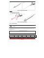
1
WISER: User Manual LAMBDA SpA Table of contents TABLE OF CONTENTS _______________________________ 1 TABLE OF FIGURES_________________________________ 3 SYMBOLS ________________________________________ 6 WARNING________________________________________ 7 DISPOSAL _______________________________________ 8 CE CONFORMITY MARKING __________________________ 8 CE CONFORMITY STATEMENT_________________________ 9 INTRODUCTION __________________________________ 10 CAP. 1 SAFETY INSTRUCTIONS ______________________ 12 1.1 GENERAL SAFETY MEASURES_______________________________________ 12 1.1.1 Working area ________________________________________________ 12 1.1.2 Safety labels ________________________________________________ 12 1.2 INDIVIDUAL SAFETY MEASURES ____________________________________ 15 1.3 EMC REGULATIONS (ELECTROMAGNETIC COMPATIBILITY) ________________ 16 1.3.1 List and set-up of linkable cables to the appliance ___________________ 16 1.3.2 Emissions___________________________________________________ 17 1.3.3 Immunity___________________________________________________ 18 1.4 OCULAR RISKS__________________________________________________ 21 1.5 LASER BEAM ACTION PRICIPLE _____________________________________ 22 1.5.1 Contraindications _____________________________________________ 22 1.5.2 Laser benefits with respect to traditional techniques _________________ 23 1.5.3 Collateral effects _____________________________________________ 23 CAP. 2 VIEW OF DEVICE____________________________ 24 2.1 INTRODUCTION _________________________________________________ 24 2.2 THE CONTROL PANEL _____________________________________________ 24 2.2.1 LCD colour display ____________________________________________ 25 2.3 FRONT SIDE ____________________________________________________ 26 2.4 REAR SIDE _____________________________________________________ 27 2.5 THE POWER SUPPLY ______________________________________________ 27 2.6 SUPPLIED ACCESSORIES __________________________________________ 28 Model LA3D0001.1 | Manual Code LI3D0001.2 Pag. 1 | Date 25-09-2009 2.7 SYSTEM SWITCHES ______________________________________________ 28 CAP. 3 SYSTEM USE _______________________________ 29 3.1 PRE-OPERATIVE INSTALLATION_____________________________________ 29 3.1.1 External interlock network (optional) _____________________________ 30 3.1.2 Preparation of the handpiece____________________________________ 31 3.1.3 Tip bending _________________________________________________ 32 3.1.4 How to insert/remove the tip ___________________________________ 33 3.1.5 Tips preparation _____________________________________________ 34 3.1.6 Preparation of handpiece for bleaching – Wide area __________________ 36 3.1.7 Preparation of handpiece for bleaching – Small area _________________ 36 3.1.8 Sterilization of the tips and accessories ___________________________ 37 3.2 SYSTEM - POWER ON - PROCEDURE__________________________________ 38 3.3 LASER SOURCE ACTIVATION PROCEDURE _____________________________ 39 3.3.1 Laser emission_______________________________________________ 40 3.4 PROCEDURE FOR DEACTIVATE LASER SOURCE _________________________ 40 3.5 PROCEDURE FOR SWITCHING OFF THE SYSTEM ________________________ 41 3.5.1 Emergency stop______________________________________________ 41 3.6 BATTERY OPERATION _____________________________________________ 42 3.6.1 Battery level indication ________________________________________ 43 3.6.2 Storage battery level __________________________________________ 43 3.6.3 Battery Charge / internal battery ________________________________ 43 CAP. 4 CONTROL PANEL ____________________________ 44 4.1 INTRODUCTION _________________________________________________ 44 4.2 MEANING OF GRAPHIC SYMBOLS____________________________________ 45 4.3 EMISSION PARAMETERS __________________________________________ 47 4.3.1 Power settings _______________________________________________ 47 4.3.2 Treatment duration settings (Timer) ______________________________ 48 4.3.3 Emission mode settings ________________________________________ 49 4.3.4 Pulse modality with fix parameters _______________________________ 50 4.3.5 Manual mode functioning ______________________________________ 50 4.4 USE OF RED POINTER_____________________________________________ 52 4.5 USE OF APPLICATION FIELD________________________________________ 53 4.5.1 Application field selection ______________________________________ 53 4.5.2 Application selection __________________________________________ 54 4.5.3 How to save application field parameters __________________________ 55 4.5.4 How to recall default parameters ________________________________ 55 4.6 SYSTEM MENU __________________________________________________ 57 4.6.1 How to enter/escape system menu _______________________________ 57 4.6.2 Language ___________________________________________________ 58 4.6.3 Password setting _____________________________________________ 58 4.6.4 Contrast settings _____________________________________________ 59 4.6.5 Setting display standby time ____________________________________ 61 4.6.6 Main menu background setting __________________________________ 61 4.7 SOUND ALARM SETTING __________________________________________ 62 CAP. 5 SYSTEM ERRORS ____________________________ 63 5.1 SYSTEM ERROR VISUALIZATION MODE____________________________________ 63 5.2 DESCRIPTION OF ERROR MESSAGES _________________________________ 64 5.2.1 Interlock not connected________________________________________ 64 Model LA3D0001.1 | Manual Code LI3D0001.2 Pag. 2 | Date 25-09-2009 5.2.2 Overheating/Temperature error _________________________________ 64 5.2.3 System error / Electric failure ___________________________________ 64 CAP. 6 CLEANING AND MAINTENANCE_________________ 65 6.1 GENERAL CLEANING INSTRUCTIONS _________________________________ 65 6.2 GENERAL MAINTENANCE INDICATIONS_______________________________ 66 CAP. 7 TECHNICAL SPECIFICATIONS __________________ 67 7.1 GENERAL SYSTEM FEATURES _______________________________________ 67 7.2 LASER SOURCE SPECIFICATIONS ___________________________________ 68 7.2.1 Diode laser source ____________________________________________ 68 7.3 OPERATING FEATURES____________________________________________ 69 CAP. 8 APPLICATIONS ERRORE. IL SEGNALIBRO NON È DEFINITO. 8.1 INTRODUCTION _________________________________________________ 69 8.2 OPERATING AREA________________________________________________ 69 8.3 LASER ACTION PRINCIPLE _________________________________________ 71 8.3.1 The tissue as an optic conductor _________________________________ 71 8.3.2 Laser–tissue interactive diagram_________________________________ 72 8.3.3 Thermic interaction ___________________________________________ 73 8.3.4 Thermal relaxation time of the tissue _____________________________ 76 8.3.5 Photomechanical interaction ____________________________________ 77 8.3.6 Photomechanical processes _____________________________________ 77 8.3.7 Photochemical interaction ______________________________________ 78 8.3.8 Photoablate process __________________________________________ 78 8.4 EXAMPLES OF TREATMENTS________________________________________ 78 8.5 CONTRAINDICATIONS ____________________________________________ 78 8.6 COLLATERAL EFFECTS ____________________________________________ 78 8.7 LASER BENEFITS WITH RESPECT TO TRADITIONAL TECH _________________ 79 CAP. 9 WARRANTY ________________________________ 80 Table of figures FIG. 1.1 SAFETY LABEL ____________________________ 12 FIG. 1.2 LIST OF SAFETY LABELS _____________________ 14 FIG. 1.3 SECURITY LABEL POSITION __________________ 14 FIG. 1.4 SET-UP CABLE DURING TESTS ________________ 16 FIG. 2.1 THE CONTROL PANEL _______________________ 24 Model LA3D0001.1 | Manual Code LI3D0001.2 Pag. 3 | Date 25-09-2009 FIG. 2.2 LCD DISPLAY _____________________________ 26 FIG. 2.3 FRONT SIDE ______________________________ 26 FIG. 2.4 REAR SIDE _______________________________ 27 FIG. 2.5 SYSTEM SWITCHES_________________________ 28 FIG. 3.1 INTERLOCK_______________________________ 30 FIG. 3.2 THE HANDPIECE ___________________________ 31 FIG. 3.3 OPTICAL TIP INSERTING ____________________ 34 FIG. 3.4 OPTICAL TIP REMOVAL______________________ 34 FIG. 3.5 DIMENSION OF TIP ________________________ 34 FIG. 3.6 PREPARATION OF HANDPIECE FOR BLEACHING __ 36 FIG. 3.7 PREPARATION OF HANDPIECE FOR BLEACHING __ 36 FIG. 3.8 ACCESS CODE REQUIREMENT _________________ 38 FIG. 3.9 LASER IN READY STATE _____________________ 39 FIG. 3.10 LASER IN OPERATE STATE __________________ 39 FIG. 3.11 BATTERY LEVEL INDICATION ________________ 43 FIG. 3.12 STORAGE BATTERY LEVEL __________________ 43 FIG.4.1 THE CONTROL PANEL________________________ 44 FIG.4.2 PULSE PARAMETERS ________________________ 49 FIG.4.3 APPLICATION FIELD MENU ___________________ 53 FIG.4.4 APPLICATION FIELD MENU ___________________ 54 FIG.4.5 CONFIRMATION OF SAVING PARAMETERS OF MODIFIED APPLICATION FIELDS _____________________ 55 Model LA3D0001.1 | Manual Code LI3D0001.2 Pag. 4 | Date 25-09-2009 FIG.4.6 CONFIRMATION SCREEN OF DEFAULT PARAMETRY RECALL_________________________________________ 56 FIG.4.7 SYSTEM MENU _____________________________ 57 FIG. 8.1 ABSORPTION OF LIGHT BY WATER AND TISSUES _ 71 FIG. 8.2 LASER-TISSUES INTERACTIVE DIAGRAM ________ 73 TABLE OF TABLES TAB.1.1 ELECTROMAGNETIC EMISSIONS _______________ 17 TAB.1.2 ELECTROMAGNETIC IMMUNITY________________ 18 TAB.1.3 ELECTROMAGNETIC IMMUNITY – RECOMMENDED SEPARATION DISTANCE____________________________ 19 TAB.1.4 RECOMMENDED SEPARATION DISTANCE EXAMPLES ______________________________________ 20 TAB.4.1 MEANING OF GRAPHIC SYMBOLS ______________ 46 PULSE MODALITY WITH FIX PARAMETERS _____________ 50 TAB.4.3 TON AND TOFF SELECTION FIELDS FOR MANUAL MODE __________________________________________ 50 TAB.4.4 TABLE OF THE TON AND TOFF VALUES ADMITTED FOR THE MANUAL MODE _______________________________ 51 TAB. 7.1 SPECIFICATION TABLE _____________________ 67 TAB. 7.2 LASER SOURCE SPECIFICATIONS _____________ 68 TAB. 7.3 OPERATING FEATURES______________________ 69 TAB.8.1 HISTOLOGICAL CHANGES INDUCED BY PHOTOTHERMIC PROCESSES ________________________ 73 Model LA3D0001.1 | Manual Code LI3D0001.2 Pag. 5 | Date 25-09-2009 Symbols Symbol “Caution” The text enclosed in this space and sided by the symbol “Caution” warns the user to pay the utmost attention to the present indications, that imply danger. Symbol “Information” The text enclosed in this space, sided by the symbol “Information”, gives useful information regarding the laser device. Model LA3D0001.1 | Manual Code LI3D0001.2 Pag. 6 | Date 25-09-2009 Warning The following manual has been written up referring to products LA3D0001.1 and LA3D0001.2, LA3D0001.3, LA3D0001.4. These products are different from one another only for their wavelength, respectively 808nm, 940nm, 980nm and 1064nm. If not differently specified, by referring to LA3D0001.1, we will make reference also to the other device. Where it is necessary to distinguish among the two products, it will be suitably shown. These laser equipment are medical devices, and their application fields are: • • • SURGERY DENTISTRY THERAPY The manufacturer is not responsible for the direct and indirect effects due to the use of the system. These effects remain under the direct responsibility of the medical staff carrying out the operation. We therefore recommend the user to respect the following instructions: The system must be used in conformity with the instructions contained in this manual, concerning both safety measures and use of the system; The installation, and any operation of alteration, calibration and maintenance must be made only by qualified staff authorized by the manufacturer; The electric system of the environment to which the laser is meant for must be in accordance both with the IEC regulations and the local prescriptions in force; The manufacturer, the assembler, the installer and the importer consider themselves responsible for the safety, reliability and performance of the device, only if the points mentioned above are respected. The manufacturer makes the technical details of design outlines and test instructions available, prior to written request, so that the qualified personnel authorized by LAMBDA SpA will be enabled to repair or maintain those parts of the system that the manufacturer consider as possible to repair. Model LA3D0001.1 | Manual Code LI3D0001.2 Pag. 7 | Date 25-09-2009 DISPOSAL Disposal of Old Electrical & Electronic Equipment (Applicable in the European Union and other European countries with separate collection system) This Symbol on the product or on its packaging indicates that this product shall not be treated as household waste. Instead it shall be handed over to the applicable collection point for the recycling of electrical and electronic equipment. By ensuring this product is disposed of correctly, you will help prevent potential negative consequences for the environment and human health, which could otherwise be caused by inappropriate waste handling of this product. tHe recycling of materials will help to conserve natural resources. For more detailed information about recycling of this product, please contact your local city office, your household waste disposal service or the shop where you purchased the product. CE conformity marking 0476 Model This product is marked with the CE label according to the European standard applicable for medical devices: CEE 93/42. The number 0476 reported under this label indicates the competent body that has issued this certification. The office responsible for the product is: LAMBDA SpA Via dell’Impresa, 36040 Brendola (VI) ITALIA www.lambdaspa.com [email protected] LA3D0001.1 | Manual Code LI3D0001.2 Pag. 8 | Date 25-09-2009 CE Conformity Statement For the devices coded as follows L A 3D0 001._ S/n ______ manufactured by LAMBDA SpA According to part II of standard 93/42/CEE issued with Law Decree 46/97. The writer LAMBDA SpA, seated at Via dell’impresa –36040- Brendola, Vicenza, manufacturer of the above mentioned devices, takes responsibility to state that: such devices do fulfil all necessary qualifications required by Standard 93/42/CEE, Part I about the Medical Devices; their design, production and final check-up are carried out according the relevant instructions taken from Quality Guarantee System certified on 31/01/2001 by CERMET, according to the prescription from Standard 93/42/CEE, part II. The firm also does guarantee and takes responsibility to state that: 1. The devices are to be considered as belonging to Class II B. 2. The manufacturer engages himself in keeping and leaving at disposal of the Qualified Authority the following technical documents, as specified in Part II, paragraph 6.1, of Standard 93/42/CEE for a period of five years since the ultimate date of manufacture of the product: a. b. c. The present conformity statement; The documents relevant to the Complete Quality Guarantee System The comments to the Notified Company relevant to possible equalising or correction in the Complete Quality Guarantee System Details relevant to the design, manufacture, sterilising and performance of the product; Decisions and reporting by the Notified Company, relevant to the revision of the Complete Quality Guarantee System; Decisions and reporting by the Notified Company, relevant to the examination of the design of the product; Decisions and reporting by the Notified Company, relevant to possible changes in the design Decisions and reporting by the Notified Company, relevant to periodic inspections Decisions and reporting by the Notified Company, relevant to unexpected inspections d. e. f. g. h. i. Stamp and signature: Model LA3D0001.1 | Manual Code LI3D0001.2 Pag. 9 | Date 25-09-2009 Introduction Particular care has to be taken during the operation of installation and transport due to its rather delicate role. It is extremely important to give scrupulous attention to the rules illustrated in the following instructions. The first fundamental operation to take into careful consideration is the checking of the shipped parts and their installation in the chosen working area. WORKING AREA In the room previously prepared for the laser use, it is advisable to remove all useless (above all easily inflammable, see paragraph 1.2, chap. 1) material and verify the electric power panel is in conformity with the current safety norms. Take careful attention that the support board is steady, even and without irregularities of any kind. Moreover, check the electric powering matches the laser system electric requirements. The laser place of use will have to be identified with the appropriate labels supplied together with laser accessories, see chap. 1. HANDLING ON LASER ARRIVAL The casing containing the laser system and all its equipment weighs about 1 kg. The manufacturer does not assume any responsibility in case of nonobservance or inadequacy of all the precautionary measures in the handling of this type of device. CHECK ON DELIVERY On arrival of the goods and in the presence of the carrier, it is highly important to pay accurate attention that the shipped material is correct and intact. These checks have to be particularly carried out: Checking of the number of parcels and corresponding relative codes. Checking of the outside packaging conditions and inside damaged parts. It is important to immediately notify the carrier of all possible non-conformities found during checking. The manufacturer states that in accordance with national and international laws, the customer always takes full responsibility for the shipped goods. Moreover, unless previously specified at the moment of stipulating the contract, the goods are always shipped without insurance. Model LA3D0001.1 | Manual Code LI3D0001.2 Pag. 10 | Date 25-09-2009 INSPECTION OF ELECTRIC CONNECTIONS It is highly important to check the power cable is undamaged before using the laser system. In particular, the cable plug must be compatible with the powering network socket. Do not use adapters or multiple sockets of any type. Moreover, the electrical network must provide an efficient grounding protection. INSTALLATION AND FOLLOWING HANDLINGS At the moment of installation or during necessary movements of the laser system, it is recommended to scrupulously follow these indications: Always use packaging material supplied on delivery for transport. Ascertain that the power switch be pressed off. Disconnect all cables connected to the laser system main body and in particular the power cable. Ascertain the fiber connector be plugged with the special cap supplied. Place the laser device at a safety distance in respect to other machinery, avoiding possible electromagnetic interference. After having chosen the laser place of use, set the device in a steady position, paying attention to check the support board does not present irregularities. Keep the laser in a dry place with a temperature from 15 to 30° C and humidity from 30 to 70%. Be sure that the device has been maintained in these environment conditions at least for 2 hours before turning the device on. It is advisable to keep the laser away from direct sun light, avoiding possible system overheating. Do not place the laser next to walls or other locations that could decrease laser air change. While working do not cover the machine with things or clothes. Model LA3D0001.1 | Manual Code LI3D0001.2 Pag. 11 | Date 25-09-2009 CAP. 1 Safety instructions This laser device has been projected respecting the present norms concerning safety for electric and medical devices. Despite this it is necessary to adopt some important safety measures to avoid sometimes even mortal accidents. The system LA3D0001.1 is a medical equipment. Three are the treatments this equipment is designed for: Surgery Dentistry Therapy 1.1 GENERAL SAFETY MEASURES During its normal use, the laser LA3D0001.1 exposes the human body to laser light radiation; therefore it is important to scrupulously read and follow all the safety dispositions listed in this chapter. Never let the connector plug of the diode's optical fiber without protection. The optics placed inside this port is very delicate and subject to break easily in case of penetration of liquids, smoke, steam or things of other kind. Absolutely avoid putting fingers inside this port and looking directly inside. 1.1.1 Working area After the device has been delivered and its content checked it is necessary to prepare the place where the laser will be used. Doors must limit the working area, and each of these doors must visibly carry a safety label like the one shown in figure 1.1: FIG. 1.1 Safety label No one other than the authorised personnel can have access to the laser system area of use. Moreover, the authorised personnel must follow all the individual safety measures (see paragraph 1.2). 1.1.2 Safety labels Model LA3D0001.1 | Manual Code LI3D0001.2 Pag. 12 | Date 25-09-2009 On the laser there are some safety labels, including danger notes for the operator and information about the laser device characteristics. The labels represented in the following must always be kept in good conditions and eventually replaced with the spare-labels you will find in your accessories. In order not to ruin these labels, it is recommended to use non-aggressive products as you clean the laser. Figure 1.2 represents the type and figure 1.3 the position of safety labels. Meaning of the different labels: ET-1: warning label hazard symbol. ET-2: emergency stop ET-3: explanatory label. ET-4: information, rear label with symbol, laser aperture, laser aperture at the end of the fiber. ET-5: information label with symbol. ET-6: storage conditions information label Caution! Consult the user manual for additional information Interlock connector Footswitch connector Recycling –Use separate collection Fuse Model LA3D0001.1 | Manual Code LI3D0001.2 Pag. 13 | Date 25-09-2009 FIG. 1.2 List of safety labels FIG. 1.3 Security label position Model LA3D0001.1 | Manual Code LI3D0001.2 Pag. 14 | Date 25-09-2009 1.2 INDIVIDUAL SAFETY MEASURES All the safety measures reported in the following must be scrupulously followed in order to avoid accidental exposures to laser radiation. The personnel authorised to work inside the laser working area must wear the protection glasses at hand. Never direct the laser beam towards eyes. Never look at into the fiber connector. The fiber connector must always be covered either by the fiber or the protection plug (fig.2.3 c). Eliminate from the operative area all reflecting and metallic objects, including personal belongings such as watches and rings since these objects risk reflecting the laser beam. In case of danger immediately press the emergency button (see chapter 3 par. 3.5.1). At the end of using the laser it is recommended to turn off the main switch. The intrinsic characteristics of the diode laser ray, if not correctly used, could set some non-metallic material on fire. It is therefore advisable to follow these simple rules very carefully. Do not point the laser ray towards any clothing. We recommend that only appropriate light coloured and completely dry clothing be worn. Remove all potentially flammable materials such as paper, wood or plastic. Never use flammable gas during laser use. Any solvent or inflammable solution must be allowed to completely evaporate before using the laser. Avoid using any potentially inflammable anaesthetic or gases such as oxygen or nitrous oxide. The saturation of oxygen may ingite many types of materials such as cotton or wadding exposed to laser radiation. It is also important that all inflammable solutions normally used to disinfect be allowed to evaporate before using the laser appliance. Warning: smoke and vapour produced following the exposure to the light radiation may contain vital tissue particles. Model LA3D0001.1 | Manual Code LI3D0001.2 Pag. 15 | Date 25-09-2009 1.3 EMC REGULATIONS (ELECTROMAGNETIC COMPATIBILITY) The existence of regulations for the electromagnetic compatibility is essential to ensure the safety of the appliances and systems, in that there are electromagnetic phenomena with various levels of intensity present in the area where these appliances are normally used. This means that to ensure the electromagnetic compatibility, the device must function correctly within its foreseen working environment. The LA3D0001.1 electro-medical appliance warrants particular precautions with respect to EMC (Electromagnetic Compatibility) and must be installed and put into service in conformity with the EMC information contained in this manual. WARNING: portable and mobile radio-communication appliances can affect the operation of the LA3D0001.1 device. WARNING: the LA3D0001.1 device must not be used near or placed on or underneath other appliances. 1.3.1 List and set-up of linkable cables to the appliance A - Power cable (2mx0.75); C - Interlock cable (5m); P - Footswitch cable (2.9m); T - Power supply; EUT - LA3D0001.1 device. FIG. 1.4 Set-up cable during tests WARNING: do not use cables or accessories different from those specified. Use only cables and accessories supplied with the equipment or otherwise sold by the manufacturer. Use of alternative cables may cause possible malfunction, an increase in emissions or a reduction in immunity of the LA3D0001.1. Model LA3D0001.1 | Manual Code LI3D0001.2 Pag. 16 | Date 25-09-2009 1.3.2 Emissions Guidance and manufacturer's declaration – electromagnetic emissions LA3D0001.1 is intended for use in the electromagnetic environment specified below. The customer or the user of LA3D0001.1 should assure that it is used in such an environment. Emission test RF Emissions CISPR 11 RF emissions CISPR 11 Harmonic emissions armoniche IEC 61000-3-2 Voltage fluctuation / flicker emissions IEC 61000-3-3 Compliance Electromagnetic environment - guidance LA3D0001.1 uses RF energy only for its internal function. Therefore, its RF emissions are very low and are not likely to cause any interference in nearby electronic equipment. Group 1 Class B LA3D0001.1 is suitable for use in all establishments, including domestic establishments and those directly connected to the public lowvoltage power supply network that supplies buildings used for domestic purposes. Class A Complies Tab.1.1 Electromagnetic emissions Model LA3D0001.1 | Manual Code LI3D0001.2 Pag. 17 | Date 25-09-2009 1.3.3 Immunity Guidance and manufacturer's declaration – electromagnetic immunity LA3D0001.1 is intended for use in the electromagnetic environment specified below. The customer or the user of LA3D0001.1 should assure that it is used in such an environment. IEC 60601 test level Immunity test Electrostatic discharge (ESD) IEC 61000-4-2 Electrical fast transient/burst IEC 61000-4-4 Surge IEC 61000-4-5 Voltage dips, short interruptions and voltage variations on power supply input lines IEC 61000-4-11 Power frequency (50/60Hz) magnetic field Compliance level ±6kV contact ±8kV air ±6kV contact ±8kV air ±2kV for power supply lines ±1kV for input/ output lines ±1kV differential mode ±2kV common mode <5% UT (>95% dip in UT) for 0.5 cycle ±2kV for power supply lines ±1kV for input/ output lines ±1kV differential mode ±2kV common mode <5% UT (>95% dip in UT) for 0.5 cycle 40% UT (60% dip in UT) for 5 cycle 40% UT (60% dip in UT) for 5 cycle 70% UT (30% dip in UT) for 25 cycle 70% UT (30% dip in UT) for 25 cycle <5% UT (>95% dip in UT) for 5 sec <5% UT (>95% dip in UT) for 5 sec 3 A/m Electromagnetic environment - guidance Floors should be wood, concrete or ceramic tile. If floors are covered with synthetic material, the relative umidity should be at least 30%. Mains power quality should be that of a typical commercial or hospital environment. Mains power quality should be that of a typical commercial or hospital environment. Mains power quality should be that of a typical commercial or hospital environment. If the user of LA3D0001.1 requires continued operation during power mains interruptions, it is recommended that LA3D0001.1 be powered from an uninterruptible power supply or a battery. Power frequency magnetic fields should be at levels characteristic of a typical location in a typical commercial or hospital environment. 3 A/m IEC 61000-4-8 Note: UT is the a.c. mains voltage prior to treatment of the test level. Tab.1.2 Electromagnetic immunity Model LA3D0001.1 | Manual Code LI3D0001.2 Pag. 18 | Date 25-09-2009 Guidance and manufacturer's declaration – electromagnetic immunity LA3D0001.1 is intended for use in the electromagnetic environment specified below. The customer or the user of LA3D0001.1 should assure that it is used in such an environment. Immunity test IEC 60601 test level Complianc e level Electromagnetic environment guidance Portable and mobile RF communications equipment should be used no closer to any part of LA3D0001.1, including cables, than the recommended separation distance calculated from the equation applicable to the frequency of the transmitter. Conducted RF 3Veff IEC 61000-4-6 150kHz to 80MHz Radiated RF 3V/m IEC 61000-4-3 80MHz to 2.5GHz Recommended separation distance 3V 3V/m d = 1.2 √(P) d = 1.2 √(P) 80MHz to 800MHz d = 2.3 √(P) 800MHz to 2.5GHz where P is the maximum output power rating of the transmitter in Watt(W) according to the transmitter manufacturer and d is the recommended separation distance in metres(m). Field strengths from fixed RF transmitters, as determined by an electromagnetic site surveya, should be less than the compliance level in each frequency rangeb. Interference may occur in the vicinity of equipment marked with the following symbol: Notes: (1) At 80MHz and 800MHz, the higher frequency range applies. (2) These guidelines may not apply in all situations. Electromagnetic propagation is affected by absorption and reflection from structures, objects and people. a b Field strengths from fixed transmitters, such as base stations for radio (cellular/cordless) telephones and land mobile radios, amateur radio, AM and FM radio broadcast and TV broadcast cannot be predicted theoretically with accurancy. To assens the electromagnetic environment due to fixed RF transmitters, an electromagnetic site survay should be considered. If the measured field strength in the location in which LA3D0001.1 is used exceeds the applicable RF compliance level above, LA3D0001.1 should be observed to verify normal operation. If abnormal performance is observed, additional measures may be necessary, such as re-orenting or relocating LA3D0001.1. Over the frequency range 150kHz to 80MHz, field strengths should be less than 3V/m. Tab.1.3 Electromagnetic immunity – recommended separation distance Model LA3D0001.1 | Manual Code LI3D0001.2 Pag. 19 | Date 25-09-2009 Recommended separation distances between portable and mobile RF communications equipment and LA3D0001.1 LA3D0001.1 is intended for use in an electromagnetic environment in which radiated RF disturbances are controlled. The customer or the user of LA3D0001.1 can help prevent electromagnetic interference by maintaining a minimum distance between portable and mobile RF communications equipment (transmitters) and LA3D0001.1 as recommended below, according to the maximum output power of the communication equipment. Rated maximum output power of transmitter (W) 0.01 0.1 1 10 100 Separation distance according to frequency of transmitter (m) 150kHz to 80MHz 80MHz to 800MHz 800MHz to 2.5GHz d = 1.2 d = 1.2 d = 2.3 √(P) 0.12 0.38 1.2 3.8 12 √(P) 0.12 0.38 1.2 3.8 12 √(P) 0.23 0.73 2.3 7.3 23 For transmitters rated at a maximum output power not listed above, the recommended separation distance d in metres(m) can be estimated using the equation applicable to the frequency of the transmitter, where P is the maximum output power rating of the transmitter in Watts(W) according to the transmitter manufacturer. Notes: (1) At 80MHz and 800MHz, the separation distance for the higher frequency range applies. (2) These guidelines may not apply in all situations. Electromagnetic propagation is affected by absorption and reflection from structures, objects and people. Tab.1.4 Recommended separation distance - Examples Model LA3D0001.1 | Manual Code LI3D0001.2 Pag. 20 | Date 25-09-2009 1.4 OCULAR RISKS Eyes can be seriously damaged in case of an unprotected exposure to laser light. For this reason it is compulsory to wear protection glasses both for the operator and for the people present in the area of work. Protection glasses provided at hand are in accordance with the European norm EN 207 and have a Optical Density ≥ 5 at the wavelength of emission from the diode. Use solely glasses with the same specifications of those provided at hand. Our firm can provide protection glasses with these characteristics. According to standard EN 60825 CEI 76-2 II ed. the following quantities have been estimated: Minimum Optical Density: 4.37 (at 0.01 meters) Nominal Distance of Optical Risk: 1.4 meters Using the following data: Laser Emission Wavelength Power Model LA3D0001.1 : : : : Divergence Diameter Exposition time Observation diode continuous 808 nm 6 Watt | Manual Code LI3D0001.2 Pag. 21 | Date : : : : 440 mrad 0.2 mm 10 s Direct light 25-09-2009 1.5 LASER BEAM ACTION PRICIPLE Once excited, the laser source emits an electromagnetic radiation due to the stimulated emission and therefore with a very high directionality, of great spectral purity, with possibility to concentrate very high powers on very small surfaces. In order to provoke the desired clinical effect the laser radiation must be absorbed by the target tissue. The interaction laser-tissue deriving from it depends on the characteristics of the laser used, such as its wavelength, its effective power, on the irradiation forms, such as the radiation intensity and application field duration, and on the characteristics of the target tissue, such as its colour and properties of absorption and reflection of the substances it contains: water, hemoglobin and pigments or chromophores. The laser treatment in medicine, and in particular in dentistry, is based precisely on the absorption of radiation by water contained in the tissues, by the hemoglobin contained in the blood and by pigments or chromophores normally present in some tissues. In particular, water absorbs in infrared, with a maximum absorption around 3.000 nm; hemoglobin presents an absorption spectrum that goes from the ultraviolet to the visible (until a little less than 0,64 micrometers) with fluctuations in the visible inferior to 10 per cent. The pigments and/or different chromophores present an absorption spectrum extended from the ultraviolet to the near infrared. The radiation between 800nm and 1000nm is weakly absorbed by water and hemoglobin and presents a penetration depth of many hundreds of micrometers; Laser may be used as cutting tool, for coagulation and tissue destruction but also as therapeutic instrument of bio-stimulation, decontamination and disinfections. Such effects are normally due to a temperature rises that follow the laser tissue interaction. When a laser beam is focused on a tissue, the water included in high percentage in it, absorbs the energy transforming it in heat. With an intensity of a few watts per square millimeter the water present in the tissue rapidly begins boiling and evaporates. If it is moved along the tissue, the beam behaves as a scalpel, forming an incision whose depth depends on the intensity of the beam and the speed of movement. 1.5.1 Contraindications So far there are no contraindications known concerning the use of laser in surgery, dentistry and therapy field. It may be assumed though that in case of a coetaneous application some unwanted coetaneous reactions might occur on photosensitive or people with dark pigmentation (like some Asian and Negroid races). We suggest the user start with small dosages of energy and increase them if necessary, but estimating how the subsequent effects noticed may be sustainable and less important than the benefit reached. Model LA3D0001.1 | Manual Code LI3D0001.2 Pag. 22 | Date 25-09-2009 1.5.2 Laser benefits with respect to traditional techniques The extreme tolerability of the application field allows avoiding use of anesthesia in majority of interventions. This ensures a better relationship with the patient, especially with odontophobic patients and children. Lasing is thus a less invasive method if compared with the conventional techniques, which reduces cells disruption as well as the bleeding thanks to the haemostasis. The laser has then a strong antibacterial power, so it encourages the sterilising and anti-inflammatory effects while using it. The application field with the laser requires the patient a shorter list of sessions, let alone the short-time dental operations for the most of applications. 1.5.3 Collateral effects An inappropriate use of the laser device may cause unwanted and sometimes dangerous consequences. The laser, actually, bears some huge and beneficial effects into the human tissue at the right rates of power, frequency and treatment time. On the other hand, especially at high power rates, may cause damage vaporising or even necrotizing the tissue that has been lased. Therefore, as this kind of consequence is unwanted, the user must always be aware about the risks for the patient. But when one actually plans necrotizing a particular site, as in the photodinamic therapy or in the use as scalpel, one cannot avoid to necrotizing part of tissue very beside the “target”. The importance of such harm is essentially determined by the rates of energy on that tissue and its application time. In most cases the harm is very light and well sustainable in comparison with the benefits. We thus advise the user to very carefully check the following parameters, so as to not cause any unwanted effects on the patient: Power; Diameter of the fiber; Distance between the end of the fiber and the tissue spot; Continuous or pulsed laser emission; treatment time. The variables diameter of fiber and distance from the fiber, are used in order to decide the size of the section of the laser beam interacting with the tissue: in fact the smaller the diameter of the fiber and distance from the fiber are, the greater the power density will be. The variable applied power is used, along with the two previous ones, in order to decide the power density. The variable treatment time is used to decide the total energy or the total energy density to deliver for an treatment field. The more the treatment time is, the greater the temperature rises into the tissue will be. The variable of emission mode is a very important variable, because it allows decide both the peak power and the average power delivered. Model LA3D0001.1 | Manual Code LI3D0001.2 Pag. 23 | Date 25-09-2009 CAP. 2 View of device This chapter describes the parts of the system, which you should become familiar with before commencing use. 2.1 INTRODUCTION LA3D0001.1 is a medical device enabled to deliver laser radiation being carried onto the application spot, through an optical fiber and a tip. The reduced size makes the carriage and the settling down of it easier. Besides the external power supply included in the accessories package the unit has an internal rechargeable battery capable of providing a certain autonomy at full load. It is provided with a display with a clear and intuitive interface, which guarantees a quick learning of the use of the machine. 2.2 THE CONTROL PANEL On the front side of the machine is housed the control panel, with a led and a sequence of keys as shown in fig.2.1 being parts of it Multifunction button for selection and set up of parameters through menus Stand by/ Ready/ Operate key Multifunction button for application field selection and parameters set up through menus Orange led: light indicator Multifunction button for parameters set up of selected application field. FIG. 2.1 The control panel Model LA3D0001.1 | Manual Code LI3D0001.2 Pag. 24 | Date 25-09-2009 2.2.1 LCD colour display The LCD display is the communication interface between the appliance and the operator. Display functions: Allows you to see and modify energy values; Allow you to see and modify pulse settings: CW, MP, SP; SSP or manual set up (T.on and T.off) Allows you to set the time for the treatment in use; Allows you to see and modify the pre-set treatment in use; Allows you to see any system errors; allows you to see the stored energy to use the device in wireless remote and the charging of the internal battery; allows you see the frequency and the average power during the laser emission mode; Allows you manage several functions such as language, enablement/disenablement of sound, adjustment of display contrasts and modification of access password, display brightness regulation. The graphic display is easy to use and intuitive, showing all useful parameters required by the operator. It is divided into three sections. The upper part of the display shows the value of power, the stored energy to use in wireless remote, battery power and the duration lasting. In the middle is shows the name of the application field in use. In the lower part is indicated the emission mode. Fig. 2.2 shows the display after the initial system startup and the use of the correct key software: A) B) C) D) E) F) G) H) I) J) Model Power setting value; Timer for the application field setting; Pre-set application field indication; Pulse settings of T.on or T.off values: manual selection of paramenters or fix indications (CW, MP, SP, SSP); Stand by/ Ready/ Operate status of device; Sound mode (on/off); Aiming beam/pilot guide (on/off); Stored energy to use the device in wireless remote; Charge level of the internal battery; Frequency and the average power during the laser emission mode. LA3D0001.1 | Manual Code LI3D0001.2 Pag. 25 | Date 25-09-2009 FIG. 2.1 LCD display 2.3 FRONT SIDE The main commands are positioned on the front section of the appliance. Figure 2.3 illustrates these in detail: A - Display; B - Control panel; C - Handpiece holder; D - Indicator lamp; E - Handpiece. FIG. 2.2 Front side Do not place the laser next to walls or other locations that could decrease laser air change. Do cnot cover even partially the ventialtion grilles during the system in use. Model LA3D0001.1 | Manual Code LI3D0001.2 Pag. 26 | Date 25-09-2009 2.4 REAR SIDE The sockets for several system accessories are positioned on the rear section of the appliance. Figure 2.4 illustrates these in detail: A - Emergency button within Ready indicator Led; B - Main switch C - Footswitch socket; D - Power socket; E - Interlock socket; F - Fuse G - Optic fiber output. FIG. 2.3 Rear side Ensure that the external power socket has a sufficient earth connection. Ensure that the electrical specifications of the electrical power circuit are compatible with the system (see Chap. 7). The optic fiber is connect to the rear side and it is integrate to the laser device. It is not allowed to unplug or remove the optic fiber for any reason. 2.5 THE POWER SUPPLY The power supply provided with LA3D0001.1 fulfils the rules CEI EN 60601-1. Such power supply has the following characteristics: Input voltage: Frequency rate: Output voltage: Max output current: 100 – 240 AC 47 – 63 Hz 12 VDC 8.33 A CAUTION: never use a different power supply from the one provided. We recommend, in case of breaches or for any other needs, to address the supplier and order a same power supply or at least compatible with the one provided with the equipment. Model LA3D0001.1 | Manual Code LI3D0001.2 Pag. 27 | Date 25-09-2009 2.6 SUPPLIED ACCESSORIES Beside the footswitch and the stem for fiber support, you can find inside the package the following accessories: C - Set of optical tip D - Interlock plug E - Handpiece F - Handpiece adapter for bleaching – Wide area G - Handpiece adapter for bleaching and Therapy H - Power supply I - Laser device LA3D0 001.1 L – Protection glasses M – Tip Bending N – Manual O – Supply Cable 2.7 SYSTEM SWITCHES The LA3D0001.1 laser device is set with two switches, one for the power supply and one for the safety/Emergency of the system: General Switch Emergency Switch The general switch is placed on the rear side while the emergency button is placed on the top side at your convenience as shown in fig.2.4. The general switch, see fig 2.5, has two positions: Posizion “0”, the system is not power supplied; Posizion “1”, the system is power supplied but not connect to the net due to the presence of the battery. Emergency switch, see fig 2.5, has two positions: NOT pusched button: device with power supplied and all functions enabled. PUSHED button: device with power supplied BUT with and all functions disabled. General Switch Emergency Switch FIG. 2.4 System Switches Model LA3D0001.1 | Manual Code LI3D0001.2 Pag. 28 | Date 25-09-2009 CAP. 3 System use WARNING: The use of the commands, the adjustments and execution of procedures different from those specified herewith, can cause exposure to dangerous levels of radiation. 3.1 PRE-OPERATIVE INSTALLATION Before using the appliance it is necessary to prepare the machine by following these simple installation instructions: Remove the system with extreme care from the transport container. Insert the external interlock connector in the appropriate socket on the back of the device (see fig. 2.4-E) or the connector supplied with the equipment (a description of the interlock network is described in the following paragraph). Insert the footswitch(optional) connector in the appropriate socket at the back of the laser (see fig. 2.4-C). Skip this operation if using the finger swith in the handpiece. Insert the power cable in the appropriate socket at the back (see fig. 2.4-D) and connect to a power point. Skip this operation if using the battery supply system. Insert the optic tip, appropriately prepared (see par. 3.1.2, 3.1.3), into the handpiece, after having removed the protection cap. WARNING: on delivery of the device the handpieces and the optic tips and all the other components supplied in the packaging have not been sterilised. Before each use ensure that these parts are sterilised. WARNING: Ensure that the external power socket has a sufficient earth connection. Also ensure the compatibility with the absorption specifications as indicated in chapter 7. Ensure to switch off the laser equipment when not in use since a long period of time. (see. par 2.7). Model LA3D0001.1 | Manual Code LI3D0001.2 Pag. 29 | Date 25-09-2009 3.1.1 External interlock network (optional) The device has been fitted with a rear socket that allows you (with an optional accessory) to interrupt the emission upon confirmation of a particular event, for example the opening of a door. This accessory is not necessary if you foresee that the work area is inaccessible, for example by locking all entrances. Diagram of the interlock socket contacts located on the back of the machine (see fig. 2.4). Example of the location of an interlock alarm on an entrance door. FIG. 3.1 Interlock Do not apply any pressure to the interlock contacts. In the event an external interlock network is used, all contacts must be closed to enable the operation. Model LA3D0001.1 | Manual Code LI3D0001.2 Pag. 30 | Date 25-09-2009 3.1.2 Preparation of the handpiece WARNING: at delivery of the appliance, the optical tips are supplied in a non-sterilized making. Thus is preferable to sterilize them before each session. The handpiece supplied is made of several parts (see picture below): a) b) c) d) Front tips Removable cap Central body Lock nut FIG. 3.2 The handpiece CAUTION: There are potential hazards when inserting, steeply bending or improperly securing the optical fibers, stating that not following the recommendations of the manufacturer may lead to damage to the fiber or delivery system and/or harm to the patient or user. WARNING: when the aiming beam uses the same method of transmission as the working beam, it is a good means of verifying the system distribution integrity. If the beam spot is missing from the distal extremity of the transmission and if the intensity is reduced or seems diffused, this can indicate that the transmission system has deteriorated or is not working properly. Model LA3D0001.1 | Manual Code LI3D0001.2 Pag. 31 | Date 25-09-2009 3.1.3 Tip bending Insert the tip in the as illustrate hole. Bend the Tip towards the right to obtain the desired shape. WARNING: in the side figures the exact procedure is represented for the tip bending. Don’t respect the procedure could bring to the definitive tip’s breakup. YES NO Model LA3D0001.1 | Manual Code LI3D0001.2 Pag. 32 | Date 25-09-2009 Final Tip shape. 3.1.4 How to insert/remove the tip Insert a) Hold tight the handpiece body. b) Select the size of the tip for the use. c) Insert the tips into the handpiece hole and push it till the end. Be careful to bring the bottom of the plastic tip in contact with the handpiece. d) Right tip connection, ready to be used.(in order to avoid damage to the tips it is important to verify a correct coupling between tip and handpiece.). Model LA3D0001.1 | Manual Code LI3D0001.2 Pag. 33 | Date 25-09-2009 FIG. 3.3 Optical tip inserting Remove 1) Twist and tear the tip 2) Handpiece without tip FIG. 3.4 Optical tip removal 3.1.5 Tips preparation CAUTION: at delivery of the appliance, the handpiece and the optical tips are supplied in a non-sterilized making. Thus sterilize them before each session. The optical tips supplied are different in their length and purpose and marked with different colours: FIG. 3.5 Dimension of Tip Code Model Use LA3D0001.1 Color Figure | Manual Code LI3D0001.2 Pag. 34 Dimension | Date Quantity 25-09-2009 Ø Tip LATEN201.4 ENDO LIGHTBLUE A 25mm B 3mm C 15mm 4 200 LATPA301.4 PERIO YELLOW A 25mm B 3mm C 10mm 4 300 LATSU401.4 SURGERY GREEN A 25mm B 3mm C 5mm 4 400 LATIM301.4 IMPLANT WHITE A 25mm B 3mm C 8mm 4 300 LATHE401.4 THERAPY BLACK A 25mm B 3mm C 5mm 4 400 LAACS043.1 WHITENING GREY 1 LAACS042.1 WHITENING GREY 1 The end of the tip fitted with the handpiece connector and must be carefully plugged into the special socket lodged on the front side of the handpiece. Never leave the tip connector socket unprotected. Theparts lodged inside this port is very delicate and liable to easy breaking in case of penetration of fluids, action of smoke, steam or things of all kinds. Absolutely avoid putting your fingers into this port and watching straight in the inside (see fig. 2.3 c). The effectiveness and lifetime of the optical fiber often depend on a suitable preparation and a good cleaning. The optical tips are very fragile. We advise to avoid leaving the tips where it might be trampled or shocked. Model LA3D0001.1 | Manual Code LI3D0001.2 Pag. 35 | Date 25-09-2009 3.1.6 Preparation of handpiece for bleaching – Wide area Insert the whitening set –Wide area(see par 2.6 Supplied Accessories – F) Handpiece ready for use FIG. 3.6 Preparation of handpiece for bleaching Before to start the “Whitening Application field” in wireless mode, be sure that the Wiser is totally charged (see par.3.6 “Battery operations”). 3.1.7 Preparation of handpiece for bleaching – Small area Insert the whitening set –Small area(see par 2.6 Supplied Accessories – G) Handpiece ready for use FIG. 3.7 Preparation of handpiece for bleaching Before to start the “Whitening Application field” in wireless mode, be sure that the Wiser is totally charged (see par.3.6 “Battery operations”). Model LA3D0001.1 | Manual Code LI3D0001.2 Pag. 36 | Date 25-09-2009 3.1.8 Sterilization of the tips and accessories All the parts that can come into contact with organic parts of the patient can and must be sterilised. In particular the parts of the system that can be sterilised are: the handpiece body (ONLY COLD STERILIZATION). the optic tips The parts that can not be sterilized are: special lens for bleaching that works not in contact; WARNING: The components to be sterilised must be always be separated and prepared for sterilised, removing any possible solid organic residue. To sterilise the parts indicated the standard methodology in autoclave (at 121°C for 20 min.). The number of cycles of sterilisation in autoclave is limited and we suggest that the operator make a careful inspection of the sterilised parts after each cycle to confirm its’ integrity. In particular: For the optic tips: verify that covering does not show signs of deterioration, breakages or holes. For the accessories for the withening: verify if there are signs of abrasions, breakages or changes to the size, the structure or coloring. In the event a part has signs of deterioration or in case of doubt, ensure that the component is substituted by a new one. DISPOSAL: Do not dispose the used or damaged tips in the environment. Disposal must always conform to national and/or regional laws in place. Model LA3D0001.1 | Manual Code LI3D0001.2 Pag. 37 | Date 25-09-2009 3.2 SYSTEM - POWER ON - PROCEDURE WARNING: Before following the system start up procedure ensure that all safety measures described in this manual have been put into place. After having carried out installation and system preparation (see previous paragraphs) you can start up the device by the following actions: Verify the correct power cable has been connected Activate using the main switch on the rear of the machine (see fig.2.4 b) The system shows a start up screen like the follow: Note: the start message may be different of this one and may be modify by manufacturer without notification. Thus, the system asks for an access code (after 5 seconds from the intro screen) Insert the access code. The initial default factory password is: "UP"key for four time (the first button at the top of the touch pad). FIG. 3.8 Access code requirement The access password can be changed at any time by using the appropriate function from the menu (see Chap. 4). After having inserted the correct password the system will activated and proceed in standby status showing on display the settings of the last treatment used (see fig.2.2). Model LA3D0001.1 | Manual Code LI3D0001.2 Pag. 38 | Date 25-09-2009 3.3 LASER SOURCE ACTIVATION PROCEDURE After system start up the system will go to the STAND-BY mode: - The laser source will not be active. - Emission parameters set depending on the last program used. - Finger switch (or Footswitch in case -optional) is not enabled. You can quickly modify the emission parameters using the function keys (see Chap. 4) To activate the laser, carry the following actions out: From the “Stand By” state, push “ready/stand by/operate”(see Tab 4.1) key: the Ready Indicator yellow colour light turn on and the indicator lamp start blinking (see fig.2.3 D). If there are no errors, the system keeps in Ready state. FIG. 3.9 Laser in Ready state From the “ready” state, push “ready/stand by/operate”(see Tab 4.1) key: the Operate Indicator red colour light turn on and the indicator lamp start blinking (see fig.2.3 D). If there are no errors, the system keeps in Operate state. FIG. 3.10 Laser in Operate state At this stage the laser source is active for the laser emission The system automatically deactivates the laser source and goes to the STAND BY mode if the device is not used for several minutes. Automatically deactivation is used to safeguard the system components and to guarantee maximum safety. Do not leave the machine unsupervised with an active laser source. If you need to leave the machine even momentarily, switch off the machine. Model LA3D0001.1 | Manual Code LI3D0001.2 Pag. 39 | Date 25-09-2009 3.3.1 Laser emission After having carried out the activation of the source, the system is ready to emit laser radiation. Ensure that all safety measures have been followed and the all personnel present are wearing appropriate protection (see Chap. 1); Point the the handpiece to an appropriate target; Press finger-switch / footswitch (optional); The system starts to emit laser radiation and this is signalled both by sound and visible indicators (orange led) placed on the keyboard. The system also shows on display a picture warning for laser emission. Release finger-switch / footswitch (optional) to stop the laser emission. If the laser reaches a temperature which is too high, “overheating” or “temperature” will appear in the display. The operator should then stop their work for few minutes to allow the cooling system to lower/reduce the temperature. This automatic signal protects the laser from breakages. If the energy or the battery charge goes down the security threshold while working wireless, the icons will turn red: recharge to avoid a sudden standby of the device/laser. 3.4 PROCEDURE FOR DEACTIVATE LASER SOURCE From the “Ready” or “Operate” state push “Stand By /Ready /Operate” button(see Tab 4.1): the system goes in “stand by” status and disables the source and finger-switch / footswitch (optional) button. From Ready/Operate state is possible to deactivate the laser source (Stand by state) by pressing any key and disables COMPLETELY THE LASER SOURCE. Model LA3D0001.1 | Manual Code LI3D0001.2 Pag. 40 | Date 25-09-2009 3.5 PROCEDURE FOR SWITCHING OFF THE SYSTEM To switch off the system you will only need to take the following actions: Brind the system to the “Sstand-by” state pushing the “Stand By/Ready/Operate” button. Press the main switch (see fig.2.4 f) 3.5.1 Emergency stop Whenever there may be an emergency situation you can switch off the machine by simply pressing the emergency button (see fig.2.1 A). Any pressure applied to this button will instantaneously block the system and the eventual emission of radiation in progress. After pressing the emergency button do not forget to press the main switch. In case of emergency stop the laser get instantly blocked in all operations. When danger ceased, it is necessary to press the emergency button again in order to start and activate the machine again. Push “stop” button to block instantaneously the system and the eventual emission of radiation in progress. Press the main switch. Model LA3D0001.1 | Manual Code LI3D0001.2 Pag. 41 | Date 25-09-2009 3.6 BATTERY OPERATION The LA3D0001. 1 laser contains an internal rechargeable battery and a storage battery that guarantee the functioning of the system and the power supply when used in the wireless mode. The duration of use in the wireless mode depends on the battery level, on the storage battery level and on the laser beam settings (mode and power). When either of batteries run below the operational minimum, the system goes into the stand-by mode and displays a low battery signal and an audio signal, for about one minute. If the machine is not shut down during this phase it will automatically turn off. The control panel will not therefore allow any operation. It is strongly recommended that the device be turned off when connecting or disconnecting the power supply cable. Battery Characteristics: Type: 4 AA 1,2V 2000mAH rechargeable Maximum endurance:10 hours Minimum endurance: 5 hours Charge time: 5 hours Storage battery characteristics: Endurance at Endurance at Endurance at Charge time: maximum power in Cw: ± 3 minutes minimum power in Cw: ± 1H 50 minutes medium medium power: 45 minutes 1,5 minutes Should the duration of the battery when fully charged last less than the indicated values, or should the charge time last longer, it is recommended that the battery be replaced. CAUTION: use only battery types as specified. LAMBDA SpA declines any responsibility for the use of improper materials or incorrect placement of the battery polarity DISPOSAL: damaged or used batteries must not be dispersed in the environment. The disposal of batteries must be carried out according to national/regional legislation. The batteries can be substituted by LAMBDA SpA, who will provide to their proper disposal. Model LA3D0001.1 | Manual Code LI3D0001.2 Pag. 42 | Date 25-09-2009 3.6.1 Battery level indication The level of the battery power is graphically displayed as in fig. 3.9. FIG. 3.11 Battery level indication 3.6.2 Storage battery level The level of the battery power is graphically displayed as in fig. 3.10. FIG. 3.12 Storage battery level 3.6.3 Battery Charge / internal battery Charging takes place only if the device is connected to an external power supply. If the device is turned off (see chapter 3.5), the external power supply will only charge the batteries and not the storage battery. Turn on the laser (chapter 3.2) to begin charging the storage battery. Model LA3D0001.1 | Manual Code LI3D0001.2 Pag. 43 | Date 25-09-2009 CAP. 4 Control panel WARNING: The use of commands, adjustments and execution of procedures different from those specified herewith, can cause exposure to dangerous levels of radiation. 4.1 INTRODUCTION The control panel is made up of a display and a keyboard which allows the intervention and modification of various machine parameters by the operator. For best understanding, illustrations and details are given here below (see chap. 2), with respect to the function of each key. A. Multifunction button for selection and set up of parameters through menus B. Stand by/ Ready/ Operate key C. Multifunction button for application field selection and parameters set up through menus D. Orange led: light indicator E. Multifunction button for parameters set up of selected application field. FIG.4.1 The control panel Model LA3D0001.1 | Manual Code LI3D0001.2 Pag. 44 | Date 25-09-2009 4.2 MEANING OF GRAPHIC SYMBOLS Symbol Description Emergency stop Stand By/Ready/Operate - Multifunctional Button Stand By/Ready/Operate key: Into main menu: • Confirm value of selected parameters. • Turn to standby – ready – operate (desable the laser / load shot paremetres / enable the laser) Into system menu: • Confirm selected parameter. Into treatment menu: • Confirm the selected treatment Into application field menu: • Confirm the selected application field. Up key: Into main menu: • Increase value of selected parameters. Into system menu: • Move between the menu options. Into treatment menu: • Move between the treatment options Into application field menu • Move between the application field options. DownUp key: Into main menu: • Decrease value of selected parameters. Into system menu: • Move between the menu options. Into treatment menu: • Move between the treatment options Into application field menu • Move between the application field options. Model LA3D0001.1 | Manual Code LI3D0001.2 Pag. 45 | Date 25-09-2009 Main menu key Into main menu: • Select the application field menu. Into system menu: • Not Active Into treatment menu: • Select the system menu Into application field menu • Save the parameters only if an application field has been modified by the user (an asterisk near the treatment will appear). Recall key Into main menu: • Select/confirm value of selected parameters. Into system menu: • Not Active Into treatment menu: • Not Active Into application field menu • Recall default parameters if an application field has been modified by the user (an asterisk near the application field will appear). Right key Nel menu principale: • Select value of selected parameters.. • Select the laser beam. Into system menu: • Not Active Into treatment menu: • Not Active Into application field menu • Not Active Left key Into main menu: • Select value of selected parameters. • Select sound activation/deactivation Into system menu: • Return to the main menu Into tretament menu: • Return to the main menu Into application field menu • Return to the treatment menu Tab.4.1 Meaning of graphic symbols Model LA3D0001.1 | Manual Code LI3D0001.2 Pag. 46 | Date 25-09-2009 4.3 EMISSION PARAMETERS LA3D0001.1 system allows the operator to have a full control on the settings of the laser radiation. The various parameters are: Power: Power of laser radiation (0.1÷10.0W) Timer : control the duration of application field(off ÷ 10 min Mode : CW : Continue Wave (continuous emission) MP : Medium Pulse (Ton=200ms, Toff=500ms, ~1.5Hz) SP : Super Pulse (Ton=10ms, Toff=10ms, ~50Hz) SSP: Super Super Pulse (Ton = 20µs, Toff = 20µs, ~ 20KHz) Ton/Toff: manually customizable These parameters may be set manually or recalled from configurations stored on the system (treatment programs). 4.3.1 Power settings The system LA3D0001.1 allows to set the pulse power: this means the power of laser radiation during Ton time only. It must be specified that the peak power of the pulse and the average power delivered within the pulse time will both coincide in case of continuos operating only, while in all other cases, the average power delivered will be lower than the peak power. The system displaysaccording tor each power setting (see Fig 2.2), the average power in relation to the T.on time selected. Procedure to set the power: From “Stand by” status press Enter key once. The background of the power window turn in red. Use Up and Down keys to set the desired value. The value can be changed from 0.1W to 5.0W with step of 0.1W. Press Enter key to esc from the setting function, or press Stand by/ Ready/ Operate key to esc setting function. Model LA3D0001.1 | Manual Code LI3D0001.2 Pag. 47 | Date 25-09-2009 4.3.2 Treatment duration settings (Timer) The system gives you the option to set a specific duration for an application field so that laser emission is automatically interrupted at a predetermined amount of time. In this way it is possible to use the laser for single treatments, and the operator does not need to block the laser emission manually. Procedure to set the treatment time: Press Enter key (in stand by status). Press “Right” key. The background of the timer window turn in red. Use Up and Down keys to set the desired value. The value can be changed from "off" state (timer off) to 10min with step of 1sec. Press Enter key to esc from setting function, or press “Stand By/Ready/Operate” key to esc setting function. CAUTION: the Timer indicates the time passing and is in no way bound to the time parameters of the pulse. The emission laser starts in the ready state from the pressure of the footswitch and this operation starts the timer. If the footswitch is released then the emission is immediately interrupted even if the timer has not finished counting down because the footswitch has total priority over the interruption. Viceversa if the footswitch is kept pressed, in which case it is the timer with the finished counter which interrupts the laser emission. At this point to effect a new exposure you need to release the footswitch and then press the footswitch again. At each pressure on the footswitch, in the case of the anticipated interruption of exposure, the timer restarts the counter from where it stopped. During the treatment, the value of the timer on the display is decreased allowing the operator to control the remaining time. Model LA3D0001.1 | Manual Code LI3D0001.2 Pag. 48 | Date 25-09-2009 4.3.3 Emission mode settings The system LA3D0001.1 allows three option for emission mode: Pulse modality with fix parameters: a) Continuous emission (CW) b) Medium pulse (MP) c) Super pulse (SP) d) Super Supreme pulse (SSP) Manual Pulse modality a) Manual user The choice of emission mode set the parameters of laser pulse: - Ton : pulse duration - Toff : time between two pulses Ton Toff FIG.4.2 Pulse parameters Ton and Toff vcan be modified with values from 20µs until 30S included the CW mode, (Continuous Wave), MP, SP, SSP. By modifying Ton and Toff, other parameters of the system also will change with the pulse shape, like the frequency and the average power. These parameters are displayed in the Window applications(vedi fig.2.2 J), where the accumulated energy during the treatment and the exposure time appear as well. Therefore, during the modification of either Ton or Toff it will be noticed that the figures displayed in Window applications have changed. Model LA3D0001.1 | Manual Code LI3D0001.2 Pag. 49 | Date 25-09-2009 4.3.4 Pulse modality with fix parameters The parameters Ton and Toff of the default treatments become fix values according to the CW, MP, SP, SSP mode as shown on the display. The following table shows the relative Ton and Toff values already set: Mode Ton Toff Frequency related CW ∞ 0 Continuous emission MP 200ms 500ms ~ 1.5Hz SP 10ms 10ms ~ 50Hz SSP 20µs 20µs ~ 25KHz Pulse modality with fix parameters The power value shown at the top of the display refers to the emission power for the Ton time (see picture 2.2A), while the one at the bottom refers to the average power during the whole period selected (Ton plus Toff). It is possible to modify manually the Ton and Toff values and then recall to the default value following the “how to recall the default vales” procedure 4.3.5 Manual mode functioning This mode allows the operator to select the laser emission type, which is the application average power and frequency. It may happen that an automatic change is noticed in the variable Toff simultaneously when modifying the Ton value. This is a forecasted function provided to keep reasonable values in the parameters. In fact, it is not possible to set values making either parameter more than a hundred times higher than each other. E.g., if Ton = 100ms, Toff cannot be higher than 10s nor lower than 1ms. In the following table the Ton and Toff minimum and maximum values are stated: Minimum Ton Maximum Ton Minimum Toff Maximum Toff 20µsec 30sec 20µsec 30sec Tab.4.3 Ton and Toff selection fields for manual mode Model LA3D0001.1 | Manual Code LI3D0001.2 Pag. 50 | Date 25-09-2009 Values admitted in 20µsec ÷ 100µsec field 20µs / 30µs / 40µs / 50µs / 60µs / 70µs / 80µs / 90µs Values admitted in 100µsec ÷ 1msec field 100µs / 200µs / 300µs / 400µs / 500µs / 600µs / 700µs / 800µs / 900 µs V Values admitted in 1msec ÷ 10msec field 1ms / 2ms / 3ms / 4ms / 5ms / 6ms / 7ms / 8ms / 9ms Values admitted in 10msec ÷ 100msec field 10ms / 20ms / 30ms / 40ms / 50ms / 60ms / 70ms / 80ms / 90ms Values admitted in 100msec ÷ 1sec field 100ms/200ms/300ms/400ms/500ms/600ms/700ms/800ms/900ms Values admitted in 1sec ÷ 30sec field from 1 ÷ 30 sec with steps of 1 sec Tab.4.4 Table of the Ton and Toff values admitted for the manual mode Procedure to set Ton and Toff parameters From the standby mode press the Enter / Recall key Push 2/3 times the “Right “ key. Respectively background to select the Ton or Toff turn in red color Use Up and Down keys to set increase or decrease the Ton or Toff values. See Tab 4.4 for the admitted values. Press Enter key to esc from the setting functions OR Press directly the “Stand By/Ready/Operate”key to esc from the Ton o Toff setting. Model LA3D0001.1 | Manual Code LI3D0001.2 Pag. 51 | Date 25-09-2009 4.4 USE OF RED POINTER The unit is supply with an ausiliar light source as known as red pointer (aiming/laser beam). It is a low level power unit visible in the red spectrum. If activated, it is visible in “operate” state only. Procedure to set on/off the red pointer: From “Stand By” state, push the “Left” key to activate/Deactivated the laser beam. The border of the red pointer Icone on display Fig- 2.2.G become in red. Press “Stand By/Ready/Operate” key to activate/Deactivate the red pointer. Activate the red pointer.. Deactivate the red pointer. WARNING: Never direct the red pointer towards eyes eventough is a low level laser source. WARNING: in “Stand By” state, the Aiming beam is always switch OFF eventough is selected ON in the main menu.. The switch of the aiming beam (if activated from the main menu) starts when there is the activation of the laser source and it remains active for all the time during the lasing. Model LA3D0001.1 | Manual Code LI3D0001.2 Pag. 52 | Date 25-09-2009 4.5 USE OF APPLICATIONS FIELDS The system can internally hold a list of programs appropriate for various types of application fields. These programs have preset names that recall application fields that have been predefined and default values for various parameters. These values are not absolute nor definitive but only indicative and are useful as a starting point for the operator given the responsibility to adapt as best they can and depending on single case, the parameters of emission. Starting with this list the operator can select the appropriate application to carry out. The programs are collect in seven fields, each one with a reserved key for a quick access of application fields menu and to the desidered operation (see fig.4.3): FIG.4.3 Treatment menu 4.5.1 Application field selection To select a field of application just follow the indication: at first pressure the display shows the first field of application. At second pressure the display shows the second application field of menu and so on. When you reach the end of list, at next pressure restart with the first. The selected application field is remarked and written in green colour (see Fig. 4.3). Procedure for the selection on application field: From the “Stand By” state press the “Menu” key: it will appear the screen shown in Fig 4.3 Use the key “Up” and “Down” to select the desidered application. The selected application is remarked and written in green colour Press the ““Stand By/Ready/Operate” to confirm the selected application fieldOR Press directly the “Left” key to esc from the treatment menu and get to the main menu without any modification. Model LA3D0001.1 | Manual Code LI3D0001.2 Pag. 53 | Date 25-09-2009 4.5.2 Application selection To select an application of a specific field just follow the indication: at first pressure the display shows the first application field of menu. At second pressure the display shows the second application field of menu and so on. When you reach the end of list, at next pressure restart with the first. The selected application is remarked and written in green colour (see Fig. 4.3). FIG.4.4 Treatment menu According to the application field selected in the menu, the parameters displayed on the bottom of the screen vary (see properties fig. 4.4). The operator can therefore immediately verify the adequacy of the set levels for the application required. The application field menu can scroll continuously: once the last application of the list is displayed, the first application of the list can be displayed by pressing the key once again. How to select a treatment: From the TREATMENT menu, select the desired field, then press the STANDBY/READY/OPERATE key: the screen will display all the application contained in the selected field. See fig. 4.4 as an example. Use the UP and DOWN keys to select the desired application. The selected title will turn green. Press the STAND-BY/READY/OPERATE key to select the application. OR Press the LEFT key to exit the application field menu and return to the main menu without modifying the settings.. Model LA3D0001.1 | Manual Code LI3D0001.2 Pag. 54 | Date 25-09-2009 4.5.3 How to save application field parameters For each application, it is possible to change the values of emission parameters ( Refer to previous paragraphs ) in order to customizethe protocol. The new values can be save for the application field in use in order to let them available for next time. Procedure for saving the application field: From application field menu, select the protocol and press the “Menu” key: The display shows a message like "Saving" to confirm the modified value. In fig. 4.5 is reported an example. Use the “Left” and “Right” keys to select the voice “Yes” and to confirm the saving operation. Press the “Stand By/Ready/Operate” key to confirma the saving. OR Use the “Left” and “Right” keys to select the voice “No” and avoid the saving operation. In application field menu, beside the name of the application modified, an icon”*” will appear to indicate the parameters in the system have been modified compared with the default values pre-set by the manufacturer. Saving modified paramenters is possible only with applications with an “*”. All the others cannot be saved. FIG.4.5 Confirmation of saving parameters of modified application fields 4.5.4 How to recall default parameters Model LA3D0001.1 | Manual Code LI3D0001.2 Pag. 55 | Date 25-09-2009 If an application has been modified, it is possible to retrieve the parameters of the laser emission pre-set for the application chosen: Procedure to retrive the default application parameter: From the application fields menu, select the chosen application and press “Recall”: the display shows the screen to load default parameters f the modified application. Fig 4.6 shows an example. Use Right and Left keys to select “Yes” to confirm default parameters Press “Stand By/Ready/Operate” to confirm selected default parameters OR Use Right and Left keys to select “No” to esc recall default parameters procedure with no changes. Press long Save/Recall key. The display shows a message like "Loading" to confirm the good result of operation. Now on display are shown the default values of parameters for the application field in use. Saving modified paramenters is possible only with application fields with an “*”. All the others cannot be saved. CAUTION: The values recovered won’t be saved automatically. Should one want to save them, it is required to store them with the Save function. CAUTION: the default values related to the various application fields are purely approximate. The manufacturer will not take any responsibility for damage or lesions due to the use of the pre-set programs or to their possible therapeutical inadequacy. FIG.4.6 Confirmation screen of default parametry recall Model LA3D0001.1 | Manual Code LI3D0001.2 Pag. 56 | Date 25-09-2009 4.6 SYSTEM MENU The system menu (see fig. 4.5) allows to perform other functions like: • • • • • Language (allows to select the language of system); Password (allows to change the access code); Contrast (allows to change the brightness while plug connected); Stand By (allows to change the time of display activity); Background (turn on/off sound advice: normally on at start up) FIG.4.7 System menu The green colour shows the selected entry The “Light” selection is disabled when used wireless: a low light is automatically set to save battery charge When turned into wireless (mode), the display light will be reduced. 4.6.1 How to enter/escape system menu From “Stand By” state press twice the “menu” key: it will display a screen as reported in Fig 4.6 TO ESC Press the “Left” key to escape from the setting menu and get back to the main menu avoiding the saving operation Model LA3D0001.1 | Manual Code LI3D0001.2 Pag. 57 | Date 25-09-2009 4.6.2 Language Is possible to set the favourite language for displaying the messages and the words appearing on the display. Use the “Up” and “Down” to select the language from the setting menu. The selection become written in green. Press the “Stand By/Ready/Operate” key to confirm the language choice: the written start blinking. Use the “Up” and “Down” to select the language required. Press the “Stand By/Ready/Operate” key to confirm the language required. OR Press the “Left” key to escape from the setting menu and get back to the main menu avoiding the saving operation After the procedure described has been carried out the display will be immediately updated with the words in the selected language and it will remain as the default language. 4.6.3 Password setting The Change password function menu allows to modify the system access code. To modify the password the old one is required. The password is made by a sequence of five keys pressing. The initial default factory password is: press “Up” key five times Procedure to change password Use Up and Down to select the password. the written code become in green color Press “Stand By/Ready/Operate” key to start the password modification. OR Press the “Left” key to escape from the password change and get back to the main menu avoiding the saving operation. Model LA3D0001.1 | Manual Code LI3D0001.2 Pag. 58 | Date 25-09-2009 When “old password” appears flashing, insert the new system code. When “new password” appears flashing, insert the new system code. When “confirm password” appears flashing, insert again the new system code. At the end of procedure the display shows a message to confirm the good result. While proceeding in this function if something goes wrong (incorrect code inserted), on display appears a message like "operation failed" and the procedure is closed without changing the code. WARNING: We suggest that the access code be immediately modified to ensure that only authorised personnel are able to use the system. In the event that the access code has been forgotten, contact the help desk service to reset the system. 4.6.4 Contrast settings The display is coloured with Led retrospective lighting. The function in menu Settings>LCD Contrast allows to display a lighter or darker side of the contents. As for function Sound, the setting is made by choosing the item in the menu, then pressing key h (Ok). Model LA3D0001.1 | Manual Code LI3D0001.2 Pag. 59 | Date 25-09-2009 Use the key Light into menu to change the display lightness Use Up and Down to select “Light/Lightness” from the menu: the entry turns green Press “Stand By/Ready/Operate” to confirm the light choice: the entry starts to flash Use Up and Down tkeys o select light/lightness. Press “Stand By/Ready/Operate” to confirm the light choice OR Press “Left” key to esc system menu and return to main menu with no changes The “Light” selection is disabled when used wireless: a low light is automatically set to save battery charge When turned into wireless (mode), the display light will be reduced. Model LA3D0001.1 | Manual Code LI3D0001.2 Pag. 60 | Date 25-09-2009 4.6.5 Setting display standby time The standby time setting function permits to set the display time ( minutes) before turning to the standby mode (disabled laser source and battery using at the minimum in wireless mode) Use Up and Down keys to select “Standby” from setting menu: the entry turns gree Press “Stand By/Ready/Operate” to confirm standby time choice: the entry starts to flash. Utilizzare i tasti “Su” e “Giù” per selezionare la tempistica desiderata (in minuti). Use Up and Down keys to select desired time (minutes) OR Press “Left” key to esc system menu and return to main menu with no changes. Press any key to reactivate display back lighting 4.6.6 Main menu background setting The background setting function permits to match a background to the main menu Use Up and Down keys to select “Background” from setting menu: the entry turns green. Press “Stand By/Ready/Operate” to confirm backgound choice: the entry starts to flash. Use Up and Down keys to select tbackground Press “Stand By/Ready/Operate” to confirm background choice OR Press “Left” key to esc system menu and return to main menu with no changes. Model LA3D0001.1 | Manual Code LI3D0001.2 Pag. 61 | Date 25-09-2009 4.7 SOUND ALARM SETTING The sound alarm informs the user when keys are pressed and the device is firing. It can be enabled/disabled during laser emission and key pressing. Sound setting procedure From standby mode press Right key to enable/disable sound The icon edge/borde turns red (fig. 2.2 F) Press “Stand By/Ready/Operate” to enable or disble sound alarm Sound ON. Sound OFF. Warning: the sound alarm is always ON / enabled when turning on the device. Warning: when sound alarm is disabled, the operator cannot be informed of laser emission. Even though visible indications are always ON, keeping also sound alarm ON is safer for the user. Model LA3D0001.1 | Manual Code LI3D0001.2 Pag. 62 | Date 25-09-2009 CAP. 5 System errors 5.1 SYSTEM ERROR VISUALIZATION MODE The device is constantly subjected to controls to internal parameters, that guarantee the safety of the device during use. WARNING: Before following the system start up procedure ensure that all safety measures described in this manual have been put into place. The systems advises the operator of any malfunction by a message on display and a warning sound (see Fig 5.1 ). The system will then put itself automatically to a safe state: the laser source will be automatically deactivate as well as the foot switch (stand by state). The system does not allow the operator to enter ready state until the causes of all the errors signalled have been resolved. If there are multiple errors, the system shows once at time following a priority list. Once an error is signalled it is necessary to repeat the activation procedure to make the laser operative. Ensure that the errors signalled by the system are noted so that they can be referred to the help desk. Model LA3D0001.1 | Manual Code LI3D0001.2 Pag. 63 | Date 25-09-2009 5.2 DESCRIPTION OF ERROR MESSAGES The errors like "Interlock not connected"or “Overheating” will shown only when user try to access ready state and only for few seconds. If there are multiple errors, the system shows once at time following a priority list. 5.2.1 Interlock not connected The external interlock network aims to block the functioning of the machine once a specific event is confirmed, for example at the opening of a door (see Chap.3 paragraph 3.1.1). a) In the event the external interlock network is present verify that the event is under control (for example, the opening of a door) or check that the connections are correct. b) In the event that the external interlock network is not present verify that the interlock connector supplied is correctly inserted in the appropriate socket. Call the help desk service if the error persists. 5.2.2 Overheating/Temperature error This type of error appears when system temperatures inside the machine is out of working range. The system independently goes into a safeguard mode, switching off all the power sections and going into stand-by state. Switch the machine off and leave it switched off in an climatised environment that are within the technical specifications for at least 5 minutes and then try switch on again. The message is accompanied by a sound warning. Call the help desk service if the error persists. 5.2.3 System error / Electric failure Signal generated in the event that the system find electric problem. Turn off the device, wait for few minutes and then turn on. Repeat laser source activation procedure. Call the help desk service if the error persists. Model LA3D0001.1 | Manual Code LI3D0001.2 Pag. 64 | Date 25-09-2009 CAP. 6 Cleaning and maintenance 6.1 GENERAL CLEANING INSTRUCTIONS WARNING: all cleaning operations must only be conducted with the machine switched off and disconnected from the power point. Never let the connector socket of the tips without protection. The diode laser lodged inside this port is very fragile and subject to break easily in case of fluid penetration, smoke action, steam or objects of any kind. Absolutely avoid putting fingers into this port and watching directly inside. Do not smoke inside the environment where the laser machine has been settled down: smoke usually may damage the diode laser irreversibly making it ineffective at all. The equipment does not require particular cleaning operation but it is advisable that the following general rules be followed: a) Keep the working area clean, using vacuum cleaners to remove and dirt and dust. b) Use a soft cloth to clean the metal or plastic surface of the machine. Take care not to damage the safety label. c) Only use detergents with very low levels of alcohol. d) Do not use sharp instruments for the areas difficult to clean. e) Absolutely don’t try to clean the inside of the cavity that houses the tip connector: the diode there lodged is particularly delicate and easily subject to break. f) Take particular care in cleaning the control panel, avoiding the use of particularly aggressive detergents. Model LA3D0001.1 | Manual Code LI3D0001.2 Pag. 65 | Date 25-09-2009 6.2 GENERAL MAINTENANCE INDICATIONS WARNING: all the maintenance operations below mentioned must be carried out by a specialised person and authorised by the manufacturer. • Recalibration of measured values by the system power. We recommend that the calibration of the system be verified at least once every year and each time the use of the system gives the impression that there is a variation in the emission values of the laser source. For the verification use a power-meter capable of measuring laser radiation wavelengths of between 800 ÷ 1100nm and a maximum power of 10W. The verification is carried out by checking that the shift between the power indicated on the display and that measured is below 20% in continuous emission mode (CW). DISPOSAL Do not disperse the laser equipment in the environment at the end of its life cycle. It is possible to entrust the laser equipment to LAMBDA SpA that will see to the disposal according to the directives on the subject Model LA3D0001.1 | Manual Code LI3D0001.2 Pag. 66 | Date 25-09-2009 CAP. 7 Technical Specifications 7.1 GENERAL SYSTEM FEATURES Tab. 7.1 Specification table Type Features Origin LAMBDA SpA Via dell’impresa 36040 Brendola (VI) - Italy Model1 L A 3D0 001.1/2/3/4 Input of power supply 100 – 240 VAC Network frequency 47-63Hz Maximum current absorbed by the network 0.5A (@230V) Output of power supply 12VDC - 8.33A max Supply voltage for the system 12VDC Max absorption of the system 0.6A Maximum power output on the work point 5W Medical class II B Isolation class I Part applied Type B This device is not suitable for use with a mixture of inflammable anaesthetic with air or oxygen or nitrogen dioxide. Protection against anaesthetics Protection level IP IPX0 Procedural use Continuous with alternative load: active 3 min, pause 2 min. Working conditions TEMP.: 10 ÷ 30 °C HUMIDITY: 30 ÷ 75% ATM. PRESSURE: 700/1060 hPa 1 The model changes according to wavelength. Model LA3D0001.1 | Manual Code LI3D0001.2 Pag. 67 | Date 25-09-2009 TEMP.: 05 ÷ 50 °C HUMIDITY: 30 ÷ 75% ATM. PRESSURE: 700/1060 hPa Storage conditions External connections Footswitch(optional) + interlock Cooling system air Laser class 4 Dimensions 9.7x13.5x18 (LxPxA) cm Weight 1 kg ca. 7.2 LASER SOURCE SPECIFICATIONS 7.2.1 Diode laser source Tab. 7.2 Laser source specifications Parameters Features Wavelength2 808±10 nm / 940±10 nm / 980±10 nm / 1064±10 nm Laser source power 10W Wavelength of aiming beam 635±10 nm Aiming beam power 2 1mW Different for the model: Model LA3D0001.1 808nm 980nm 940nm 1064nm | Manual Code for for for for LI3D0001.2 Pag. 68 LA LA LA LA | 3D0 3D0 3D0 3D0 001.1 001.2 001.3 001.4 Date 25-09-2009 7.3 OPERATING FEATURES Tab. 7.3 Operating features Type Features Power indication Digital, from 100mW to 5000mW Pulse features CW MP SP SSP Mode of emission Continuous emission Ton=200ms; Toff=500ms Ton=10ms; Toff=10ms Ton = 25µs; Toff = 25µs; Continuous or by timer Laser shutter Finger Switch Adjustment of duration of emission from 1 to 10 min. Stability of emission power ± 20% CAP. 8 TREATMENTS 8.1 INTRODUCTION LA3D0001.1 is a medical device capable of supplying light radiation at high energy to the treatment area via an optic fiber. This device was idealised for use in the following medical fields: surgery, orthodontics and therapy. In the following paragraphs the detailed clinical functionality will be defined as well as the operating area in which the device should be used, it will also describe in general terms, what the clinical action of the radiation laser is on human tissue. 8.2 OPERATING AREA LA3D0001.1 is a medical device designed for use in surgeries situated in private and public structures (hospitals, clinics, medical studies) and exclusively by specialized medical personnel. You must arrange for the removal of all extraneous material from the room where the machine is to be used and (above all inflammable see paragraph 1.2 Chap. 1), verify that the electrical power source is in accordance with safety regulations. You must also check that the power supply satisfies the electrical requirements of the Model LA3D0001.1 | Manual Code LI3D0001.2 Pag. 69 | Date 25-09-2009 equipment. The voltage and current values are listed in the general system features table in Chap 7. You must ensure that the surface where the device is to be placed is stable and that there is no likelihood of uneven surfaces or disconnections from the power supply. The laser operating environment must be identified by appropriate labels supplied with the laser accessories (see chap.1). Position the appliance at a safe distance from other appliances where there may be possible electromagnetic interference. The room in which the LA3D0001.1 will be used must respect the following environmental limits: Temperature: 10 ÷ 30°C Relative humidity: 30 ÷ 75% Atmospheric pressure: 700 ÷ 1060hPa WARNING: carefully follow all instructions for the safety measures reported individually parag.1.2 in Chap.1. Model LA3D0001.1 | Manual Code LI3D0001.2 Pag. 70 | Date 25-09-2009 8.3 LASER ACTION PRINCIPLE This paragraph will present the mode of interaction of the laser light with the biological tissue, and the consequences produced by such interaction. 8.3.1 The tissue as an optic conductor The interaction between an electromagnetic wave and a biological conductor depends on the wavelength of the radiation itself and the optic features of the tissue. Despite the structural complexity and the morphological differences, as first approximation, the organic tissues may be seen optically as homogeneous and isotropic conductors into which the propagation of the luminous radiation is described according to very important optical variables such as absorption, transmission, scattering, etc. Considering then a laser beam perpendicularly turned to the surface of the tissue, a small portion of the radiation, typically 5%, is reflected back because of the refraction index jump between the outside environment and the tissue. The remaining portion is transmitted to the tissue and will be subject to process of absorption and multiscattering. The chemical species participating in the absorption of the light in the tissue are numerous and their effect very sensibly changes on a par with the wavelength of the radiation. A very important part is covered by the water (fig. 8.1), being the main absorber in the IR spectrum. Besides, in the optic bands of the visible and the near IR, the radiation is scattered, because the cellular diameter comes similar to the wavelength. Ab s o rp tio n o f lig h t b y w a te r a n d tis s u e s w ater (1/mm) Logarithmic scale Linear absorption coefficient Diode laser melanin hemoglobin W a v e le n g th L o g a rith m ic s c a l e (n a n o m e te rs ) FIG. 8.1 Absorption of light by water and tissues This process causes an effect over the light propagation reducing the real penetration depth of the radiation into the tissues. Model LA3D0001.1 | Manual Code LI3D0001.2 Pag. 71 | Date 25-09-2009 On the ground of these comments, it may be advantageous to classify the features of the laser propagation inside the biological media in function of the wavelength of the radiation: Absorption prevailing. As one may watch on diagram of fig. 8.1, the UV wavelengths including the emission lines of excimer lasers (190-350 nm) are mainly absorbed by the main organic species. A similar attitude is shown by the IR wavelengths such as those relevant to Ho:YAG, Er:YAG and CO2 (2-10 µm) lasers that undergo a massive absorption mainly by the content of water in the tissues. In these cases the penetration depth of the radiation (formally defined as L=1/α, where α is the coefficient of absorption in the tissue) turns out to be of a few dozens of micrometers and the phenomenon of the scattering may be ignored about the propagation. Absorption – scattering. In the optical portion of the spectrum where the emission lines lie of Argon, duplicated Nd:YAG and copper-vapour (450 – 570 nm) lasers, the effects of absorption and scattering will turn out equally important, with typical penetration depth of about one millimeter. Part of the luminous radiation in the tissue will be tallied and surrounded by an area where the basis will put up with multi-scattering. Scattering prevailing. In the spectral areas of IR and near IR, typically between 600 nm and 1.5 m, the tissue is provided with a transmission window for the electromagnetic transmission. On this band, which the emissions of diode laser, Dye, Nd:YAG, Alexandrite and He-Ne lasers belong to, the scattering is prevailing over the absorption and consequently the penetration depth, of about 2-8 mm, turns out to be determined by phenomena of multi-scattering rather than absorption. A portion of radiation not to neglect, will be scattered back and have the effect of rising the temperature inside the tissue with respect to that in the surface. Therefore the wave delivered by a diode laser will be propagated through the biological medium, mainly by a process of multi-scattering with a penetration depth of about 2-8 mm. Since part of the radiation is reflected back, a temperature rise will take place inside the tissue with respect to the radiated surface. 8.3.2 Laser–tissue interactive diagram The various kinds of laser – tissue interaction may be schematically represented as regions of a diagram reporting the exposure times as abscisses and the power density of the radiation as ordinate, where the diagonals stand as lines of constant fluency. Though the various kinds of biological effect in this representation will appear in a rather tidy and distinctive way, it must be considered however that in the practical treatment they will often appear overlapped, both because the intensity of the may not be constant on the radiated area, and because the portion transmitted may change during the propagation inside the tissues, as described in the previous paragraph. Model LA3D0001.1 | Manual Code LI3D0001.2 Pag. 72 | Date 25-09-2009 Mappa dell'interazione laser-tessuto Laser-tissue interactive diagram 1,E+12 FOTOMECCANICA 1,E+09 Densità di potenza (W/cm²) FOTOABLATIVA 1,E+06 1,E+03 FOTOTERMICA 1,E+00 FOTOCHIMICA 1,E-03 1,00E-12 1,00E-09 1,00E-06 1,00E-03 1,00E+00 1,00E+03 Tempo di esposizione (sec) FIG. 8.2 Laser-tissues interactive diagram The surgical treatments of the diode lasers are based for the majority of them on the conversion of the optical radiation mostly into thermal energy and partly in mechanical energy. 8.3.3 Thermic interaction In a microscopic view, the photothermic processes may be represented with the absorption of a photon by an organic molecule that bears it to an excited rotatingvibrational state, and with the successive disexcitment derived from anaelastic shock with a molecule of the surrounding medium that will have thus its kinetic energy. This process of non-radiative loss occurs within the shortest delay (1 – 100 psec) and the subsequent fast heating will give a local temperature rise. Macroscopically, the biological effects of photothermic kind may be classified according to some different thermodynamic processes which the main histological changes, summarized in the below table, will be relevant to: Tab.8.1 Histological changes induced by photothermic processes Model LA3D0001.1 | Manual Code LI3D0001.2 Pag. 73 | Date 25-09-2009 43-45°C Structure changes Shrinking Overheating (cellular death) 50°C Reduction of enzyme activity 60 °C Protein degenerating Coagulation Collagen degenerating Permeabilizzazione delle membrane 100°C >100°C 300-1000 °C 3350 °C Extracellular vacuole formation Vacuole breaking Tissue thermoablate Carbon vaporizing Low temperature effect (43 –100°C) Hypothermic regime (43-45°C, hypothermic interval). The first thermal effect put up with by the biomatter is the degenerating (breaking of the hydrogen bonds) of the biomolecules and their aggregates (proteins, collagen, lipids, hemoglobin). Around 45°C it may be noticed what follows: structure changes; bond breaking; alteration of the membrane. Every single cell and all the different tissues heated to a temperature of about 43-45°C can stand a temporary harm only; the damage will become irriversible (cell death) after prolonged exposure times, that may vary between 25 minutes and a few hours depending on the kind of tissue and conditions of radiation. In case of tumoural nature cells, the mortality is particularly high at this thermal regime. These processes find treatment in the interstice hyperthermia techniques, for the cure of tumors, typically treated by diode lasers in continuous mode. Coagulative regime. When the temperature rises higher than the degenerating value, processes of necrosis will take place (cellular) shaped as coagulation and vacuoles. Between 50°C and 60°C the enzyme activity is modified (reduced), so a considerable degenerating of the macromolecules (like proteins, collagen, lipids, hemoglobin) will begin, standing as a ground for the coagulative process. The degenerating of the collagen is important, fibrous protein broadly spread among mammals, made up of four polypeptic chains gathered to form a bi-helicoidal structure. The temperature rise destroys the space organization created by the macromelecular chains: the spirals are distributed at random with strong changes in the spectra of absorption and scattering of the optical radiation, causing a notable contraction in the collagen fibers. The thermal degenerating and the contraction of the inter-cell proteins, alongwith a possible collapse of the cytoskeleton, will produce the shrinking of the coagulated cells. The breaking of the membranes becomes prevailing in all the cells when they turn out seriously damaged after a thermal action. In the end, in those tissues where a high-standard spatial order stands, like in the muscles, the protein degenerating will upset this regular structure, with a loss of the relevant optical features. These processes of photocoagulation are used for example in ophtalmological surgery to reduce the retina coming off, and in dermatology to treat the pigment vascular lesions. Model LA3D0001.1 | Manual Code LI3D0001.2 Pag. 74 | Date 25-09-2009 Besides, laser-welding techniques have been proposed on the skin, vessels and urological ducts that are based on induced modifying of the collagen fibers through laser heating at low temperature (45 – 50°C). Medium-high temperature effects (>100°C) The prevailing effects within this range of temperature may be noticed in the water; in fact, very qualitatively assuming that the process of vaporization begins at 100°C, namely due to the heating of the water running in the tissue, the continuous radiation will determine: a)Energy absorption for the phase of transition liquid - vapor; b)Drying up of the tissue; c)Formation of vacuoles of vapor inside the tissue with consequent d)Mechanical effects caused by the fast expansion of the vapor vacuoles trapped into the tissues. The thermal ablate is featured like an explosive event even in case of radiation in continuous mode. When the temperature rises over 100°C, the max temperature will move from the surface to the inside of the tissue: the fluids in the tissue are converted into vapor with pressure over 1 atmosphere, and following to overheating, they finally explode because of the too high pressure inside of them. The removal of the warm tissue will expose a colder layer to the radiation. This layer will stay approximately at 100°C for the time taken by the radiation to dishydrate the tissue (the water gives a high vaporization heat: 2530 J/g). The loss of water will reduce the local thermal conductibility and will limit the heat conduction in the surrounding areas. Thermoablate induced by high temperature (between 300 to thousands °C). When the water in the cells is completely vaporized, the temperature in the tissue will increase quickly until 300°C: nuclear sites will be generated on the surface and the tissue will be burned and carbonized. The vaporization alongwith the carbonization will give way to the decomposition of the components of the tissue. The greater optical radiation intensity contributes to the temperature peak on the subsurface compared with that on the surface that occurs in the immediately inner layers of the tissue, because of the back-scattering of the radiation derived from the scattering nature of the tissue. The damage that takes place in these conditions, beside having purely thermal consequences, will give mechanical effects as well. The macroscopical bubbles (vacuoles) that form in the warmest areas of the tissue below the radiated surface, will press the tissue because of the notable increase of the volume with respect to the conversion liquid – vapor; when the critical pressure is reached, the thin walls of the vacuoles will break so these latter will gather to form larger-sized conglomerates; by radiating for a longer time the bubbles will spread until they cause kind of explosive breaks (pop-corn effect). The break of the vacuoles on the surface will allow the vapor to get outside, producing a temporary cooling of the surface. The histological analysis of the effects induced by the pop-corn effect indicate that the superficial craters thus produced are not due to any loss of tissue mass, but to the formation, expansion and break of vacuole agglomerates. Differently, the high and quick heating due to the radiation in pulsed mode will produce an explosive break of the vacuoles with explosion of tissue fragments. It is important to notice that most of the previously described thermal effects may occur simultaneously on different areas of the radiated volume, as a consequence of Model LA3D0001.1 | Manual Code LI3D0001.2 Pag. 75 | Date 25-09-2009 the different temperature values that locally develop after the laser radiation has penetrated into the tissue. Using the laser on a continuous mode in particular, beside the penetration depth, another parameter basically to check in order to circumscribe the effects of the laser radiation into the volume of the tissue to be treated is the thermal relaxation time τ in the tissue. In fact, if the laser radiation time is longer than τ, the heat has the way to scatter inside the tissue on a larger space than the typical penetration depth. 8.3.4 Thermal relaxation time of the tissue The length of scattering L, bound to time t, represents a very important parameter for the control of the thermal effects: L2 = 4 K t K being the thermal diffusivity of the material, which is in relation with the thermal conductivity, specific heat, and density. The water has K=1.43 10-3 cm2/s, so within a second the heat scatters on a length of 0.8 mm. Similarly, the scattering time associated with an blood vessel of 10 µm of diameter is about 100 µs, while for a vessel of 100 µm, this time will increase until about 18 ms. If L is equalled to the penetration length l of the optical radiation into the tissue, the thermal relaxation time τ in the tissue will be thus calculated: τ ≈ ¼ K l2 representing then the time the heat will take to spread on an optical penetration length. If the duration of the laser pulse is shorter than τ, the laser energy will stay trapped into the volume S (S = radiated surface). The strong temperature rise and the relevant thermal harm will be localized on such area, while the surrounding tissues will undergo a very moderate heating after the successive thermal scattering. There are then great differences in the τ depending on the scattering (dispersion) to be prevailing or not over the absorption. These concepts are applied to selectively effect the coagulation and/or the vaporization of the tissue: by choosing the wavelength of excitement so that the penetration length is almost equalled with the size of the structure of the tissue to treat (for example, a blood vessel), and adjusting the duration of the laser pulse, this latter will turn out mostly confined into this structure. By adjusting, at last, the repetition rate as well in an appropriate way, the temperature may be kept to level in the surrounding tissues, that are heated by the scattered heat generated in the absorption area for duration times longer than τ, with a value of specific harm (selective photothermolisis). Model LA3D0001.1 | Manual Code LI3D0001.2 Pag. 76 | Date 25-09-2009 8.3.5 Photomechanical interaction Short duration pulses may give birth to mechanical shock waves enabled to damage the tissue where they propagate in. The formation of the shock wave usually comes after a quick local expansion of the medium. Such photomechanical interaction involves the processes of: a) b) c) Thermoelastic expansion; Mechanical recoil due to the ejection of matter; Formation of plasma. Depending on the type of interaction the pressure wave may be classified into: I. Acoustic wave, that is low-pressure wave that propagates at sound speed; II. Shock wave, that is high-pressure wave that propagates at supersonic speed. The shock wave is characterized with a supersonic expansion speed and a very steep forehead, where the pressure rises up onto thousands of atmospheres on distances of few nanometers, creating temporary effects with rise delays of few picoseconds. 8.3.6 Photomechanical processes According to the laser pulse intensity, three borderline cases may be distinguished: in absorbent media and below the optical breakdown threshold, the generation of acoustic waves is dominated by thermoelastic effects and vaporization; in transparent media, the acoustic effects are bound to the formation of plasma, that may join up with the above effects into the absorbent media as well. Low intensity: thermoelastic effect With low energy dosages transferred to the material, the thermoelastic effect determines the thermic expansion of the layer of heated material, to which the nonspread part opposes, so a few mechanical stresses are thus formed at the limit between the two areas, that give birth to elastic waves that propagate into the mass of the material. Medium intensity: vaporization For bigger energy amounts absorbed, the vaporization in the tissue may take place, with ejection of biomaterials, the recoil of which will generate elastic waves and the inertial confinement (constant-volume transferring of optical energy to the liquid contents of the tissue). For very short laser volumes, the heated volume has not time enough to spread during the pulse: a sudden rise of the inside pressure follows, and the successive quick local expansion produces acoustic waves of high intensity. High intensity: ionization and formation of plasma When either the energy density values are sufficiently high or the removal times sufficiently short, the ionization of the radiated material may be induced and the successive creation of plasma. Into the plasma extremely high values of pressure and temperature are reached (thousands of °C and atmospheres). The expansion of plasma generates a shock wave that may cause fragment-forming and local break in the tissue. Model LA3D0001.1 | Manual Code LI3D0001.2 Pag. 77 | Date 25-09-2009 8.3.7 Photochemical interaction The IR radiation (that is that coming from the diode) is little effective in producing the changes into the biological systems of non-thermic nature. Non-thermic processes may occur in case of high power peaks through two or three-photon transitions. 8.3.8 Photoablate process The laser photoablate represents a complicated process, where in different amounts a few photochemical (breaks in molecular bonds), photothermic (accumulated heat and quick vaporization of material), and photomechanical mechanisms (production of a shock wave) are included. The prevailing of either of them will depend on the characteristics of the protocol of irradiation. 8.4 EXAMPLES OF TREATMENTS TREATMENT Analgesia POWER (mW) FREQ (Hz) TIME (s) FIBER (µm) 700 CW 50 300 1000 CW 10 200 Gingivoplasty 1500 CW - 300 Herpes labialis 1000 CW 60 300 Periodontology 800 CW 30 300 Endodontics 8.5 CONTRAINDICATIONS By now no contra-indication is known about the use of a diode laser. In case of skin treatments on photosensible or coloured people (of asiatic or negroid race) some unwanted skin reaction may occur. The user will be kindly advised to start with low dosage of energy and then increase it, evaluating though wether the minor effects noticed are tolerable and less important than the benefits. 8.6 COLLATERAL EFFECTS An inappropriate use of the laser device may cause unwanted and sometimes dangerous consequences. The laser, actually, bears some huge and beneficial effects into the human tissue at the right rates of power, frequency and treatment time. On the other hand, especially at high power rates, may cause damage vaporising or even necrotizing the tissue that has been lased. Therefore, as this kind of consequence is unwanted, the user must always be aware about the risks for the patient. But when one actually plans necrotizing a particular site, as in the photodinamic therapy or in the use as scalpel, one cannot avoid to necrotizing part of tissue very beside the “target”. The importance of such harm is essentially determined by the Model LA3D0001.1 | Manual Code LI3D0001.2 Pag. 78 | Date 25-09-2009 rates of energy on that tissue and its treatment time. In most cases the harm is very light and well sustainable in comparison with the benefits. We thus advise the user to very carefully check the following parameters, so as to not cause any unwanted effects on the patient: Power; Diameter of the fiber; Distance between the end of the fiber and the tissue spot; Continuous or pulsed laser emission; treatment time. The variables diameter of fiber and distance from the fiber, are used in order to decide the size of the section of the laser beam interacting with the tissue: in fact the smaller the diameter of the fiber and distance from the fiber are, the greater the power density will be. The variable applied power is used, along with the two previous ones, in order to decide the power density. The variable treatment time is used to decide the total energy or the total energy density to deliver for an treatment. The more the treatment time is, the greater the temperature rises into the tissue will be. The variable of emission mode is a very important variable, because it allows decide both the peak power and the average power delivered.. 8.7 LASER BENEFITS WITH RESPECT TO TRADITIONAL TECH The extreme tolerability of the treatment allows avoiding use of anesthesia in majority of interventions. This ensures a better relationship with the patient, especially with odontophobic patients and children. Lasing is thus a less invasive method if compared with the conventional techniques, which reduces cells disruption as well as the bleeding thanks to the haemostasis. The laser has then a strong antibacterial power, so it encourages the sterilising and anti-inflammatory effects while using it. The treatment fields with the laser requires the patient a shorter list of sessions, let alone the short-time dental operations for the most of treatments. Model LA3D0001.1 | Manual Code LI3D0001.2 Pag. 79 | Date 25-09-2009 CAP. 9 Warranty LAMBDA SpA guarantees its clients that the products are free of defects and are guaranteed for one year. This warranty is not valid for any defect, fault or damage caused by improper use or inadequate maintenance and care. LAMBDA SpA is not obliged to provide assistance under warranty to repair damage caused by other personnel not authorised by LAMBDA SpA. In order to obtain assistance under this warranty, clients must contact LAMBDA SpA to advise the problem. The client is responsible for transport and possible insurance expenses for the return of the products to the service provider. LAMBDA SpA will repair the products under warranty with transport costs at customer’s expense. For shipping by post, rail or courier, we request that the client use the original packing. Damage caused in transit/transport or negligence is not covered by the warranty. In the case of an indication of a fault, a label has to be placed on the device container with a brief description of the faults encountered. In order to speed up the return of the device, indicate the name and telephone number (area code and telephone number, or direct number and/or department extension) of the client. Under this warranty, LAMBDA SpA will repair or exchange any product returned to the Client Service Department during the warranty period, once the technical service has examined the product and found it to be defective at the fault of LAMBDA SpA. All worn parts are not covered by the warranty. LAMBDA SpA is not responsible or at fault or with good reason, any damage or unforeseen, direct, indirect, accidental or consequent delays of the equipment during the period necessary for repairs. Model LA3D0001.1 | Manual Code LI3D0001.2 Pag. 80 | Date 25-09-2009 LI 3D0 001.5 Model LA3D0001.1 | Manual Code LI3D0001.2 Pag. 81 | Date 25-09-2009