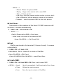
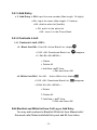
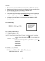
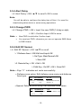
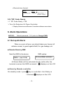
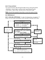
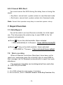
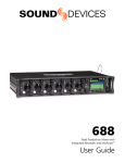
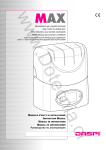
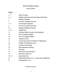
1
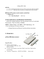
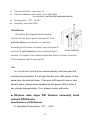
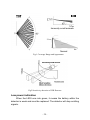
MULTI-FUNCTIONAL HOUSE ALARM SYSTEM FCT-31A USER MANUAL Ver: 1.0 Preface Thank you for choosing our GSM wireless home security products. This GSM wireless house alarm device is used in all GSM networks. This system is dedicated to serve home user. It mainly focuses on the protection of houses and premises. Before operating the terminal, please read this manual thoroughly, and retain it for future reference in order to get the best service from the terminal and us. -1- CONTENT 1. BRIEF INTRODUCTION--------------------------------------------------------------3 2. INSTALLATION-------------------------------------------------------------------------5 3. KEYBOARD & FUNCTIONS--------------------------------------------------------7 4. TELEPHONE----------------------------------------------------------------------------9 4.1 OPERATION-------------------------------------------------------------------------9 4.2 INCOMING CALL LIMITATION---------------------------------------9 BLACK LIST WHITE LIST 5. MENU OPERATIONS-----------------------------------------------------------------9 5.1 SMS--------------------------------------------------------------------------------10 5.2 PHONE BOOK-------------------------------------------------------------------12 5.3 CALL LOG-------------------------------------------------------------------------14 5.4 PHONE SETUP------------------------------------------------------------------15 5.5 ALARM SETUP-------------------------------------------------------------------17 6. ALARM OPERATIONS----------------------------------------------------------------19 6.1 SET UP ALARM------------------------------------------------------------------19 6.2 SET UP LOCAL ALARM--------------------------------------------------------20 6.3 SET UP UNARM------------------------------------------------------------------21 6.4 ALERT OPERATION-------------------------------------------------------------21 6.5 SOS ALERT------------------------------------------------------------------------23 7. REPORT FUNCTION------------------------------------------------------------------24 7.1 CHILD REPORT 7.2 WORK RECORDING APPENDIX-----------------------------------------------------------------------------------25 1. SET UP RF CODE----------------------------------------------------------- -25 2. TEST DETECTORS AND REMOTE CONTROLLERS-----------------26 3. DETECTORS ------------------------------------------------------------26 -2- 1. BRIEF INTRODUCTION FCT-31A Multifunctional House Alarm System is a multi-functional device integrating GSM fixed telephone and house alarm system. With the help of various reliable sensors and GSM communication mode (call and SMS), the house owner will be able to handle the security of the house conveniently ■ Functions and Features Z GSM Phone: Dial & Receive Calls Z SMS function: ■ Sending & Receiving & Storing SMS ; ■ SMS templates: pre-setup and fast sending Z Phone book function: Editing & Query & Storing & Dialing Z Incoming call and SMS limited: Black list and white list Z Reporting function ■ Child report ■ Work recording. Z SMS alarming and unarming function: Z Password supported Z Alarm and Alert Delay Z Backup battery: Power supply protection Z All defense and Partial defense Z Guard against theft, fire , gas, door etc. Z Z SOS: In emergent status, (elders or children) press the key on terminals or controller to send cry-for-help information out. Advanced encryption technology; Z High security level Study Code. Z Installation and use easily -3- ■ Specifications Z Z Network GSM 900/1800/1900MHz (850MHz optional) GSM antenna ■ Mobile antenna: gain 4dBi, cable length 3-5M, SMA connector ■ Portable antenna: gain 2dBi, height 10CM, SMA connector Z Receiving Frequency: 433/315MHZ (2240/1527 study Code) Z Receiving sensitivity:≤0.1uv Z Working Environment: ■ Temperature: -10 – +50℃ ■ Humidity: 20% – 95% Z Power supply: Input: AC 110~240V; Outup:DC7.5 1.5A (DC12V 1A optional) Z Back up battery:Lithium Polymer 600 mAh 3.7V Z Weight:Package weight: 1.8Kg/pcs Z Package size(mm): 325*310*72 ■ Accessories Standard Package Quantity Main Unit 1 GSM Antenna 2 Remote Control 3 Door/window magnetic sensor 2 Infrared Sensor: PIR-H 1 Siren 1 Power adaptor 1 Backup battery 1 Optional Detector Quantity Smoke Detector Gas Leakage Detector Zone 4-14: Defense area Infrared Sensor: PIR Zone15-16:Special defense area Shake Sensor -4- ● Remote controller: Working frequency: 433M/315Hz. Code: 2240/1527 study type Working Voltage: 12V ( 27A 12V dry battery) Control Distance: 20-100M : All Alarmed Mode key (all defense area alarm) : Local Alarm Mode key (Main defense alarm) : Unarm key ! : Press the key to enter into unarmed status. SOS alert key Press the key to active SOS Alert. Note: The LED light in the remote key starts flashing when it is pressed. Change the battery when the flashing light becomes vague. 2. INSTALLATION NOTICE: Z The terminal should be installed at a place with strong and stable GSM network. Z The terminal should never be put together with objects that might bring strong electromagnetic interference. Z The distance between the main terminal and each wireless sensor must be no longer than 100m. Z The terminal should be installed at a suitable place avoiding dusts, vibration, moisture, direct sunlight, high Temp or too low Temp. Z Please don’t ever try to modify the inner structure of the terminal by yourself. Z This device need to work with a valid SIM card inserted (SMS, Caller ID, Enough Balance). -5- ■ Main Frame Installation ON / OFF Power Supply Factory use only 1. Open the SIM card cover on the mainframe bottom and insert the GSM SIM card to the socket. Up side down 2. Make sure the battery is installed properly. 3. Install the GSM antenna and the Siren. 4. Plug the power adaptor with a proper AC power supply. Insert the DC output port into the power supply port on the main terminal. 5.Confirm the installation is done properly and turn the terminal on by switch. Check whether the status indicator is working properly. NO ■ Installation of the Detectors Please refer to the Appendix -6- 3. KEYBOARD & FUNCTIONS Key ▲ ▼ ◄► MENU Prompt Key Function On stand by mode check missed calls(Max 20). review the number and name by ‘▼’or ’▲’key Up direction key ●Down direction key ●During input,switch check dialed numbers(max 20). Cursor position Left/Right review the number and name by direction key ‘▼’or ’▲’key Function switch in submenu Press it to enter into the MENU OK Select in Menu operation Press it to enter the Phone Book. EXIT Cancel in Menu operation Press it to enter into SMS Menu. setup All or Local Alarmed Mode Unarm the system ! Ask for emergent helps Press it to enter the SMS templates -7- VOLUME+/- Adjust the volume of the dialing tone and call Redial the last outgoing call. REDIAL Calling without the handset Number Key Alphanumeric key * During input: cancel input # During input: Spacebar ■ SMS LED: Brighten up when new SMS is coming ■ Symbol on the LCD Network signal Alarmed Calling Local armed Unread SMS Power supplied by AC Black-list activated While-list activated Battery status - + Volume level Siren warning ■ Input Method Number: press▼> Numeral state > press Number keys Letter: ● Capital: press▼> Blank: press # key state > Input related letter ● Lowercase: press▼> state > Input related letter Character: On Delete: Press * key to delete the Number or letter before cursor state, press ‘0’ switch to character input Cursor position: ◄LEFT / ►RIGHT keys Screens switch: ▲UP Input switch: Press ▼Down key to switch between -8- . 4. Telephone 4.1 Operation: ■ Dial: ● On standby mode, press hands free button or pick up the handset, dial the target number and press OK button to make a call. ● By call>ok in Menu, call the target number out. ■ Receive when phone rings, pick up or press key to receive the call. The device supports Incoming call Number or name display. ■ Hands free Talking hands-free when dialing or receiving calls. ■ Operation in call Adjust volume 4.2 Incoming call limitation ● Black list: When Black list function is activated, LCD display , 20 phone numbers in the Black list book are refused (calls or SMS) automatically ● White list: When white list is activated, LCD display 20 phone numbers only in the white list book can be received (call or SMS). The other numbers that are not in the white list will be refused automatically. 5. MENU OPERATIONS On standby mode, press MENU button on the phone keyboard to display the Main Menu: ▲▼keys: Scroll the option in main Menu Select: OK key Cancel: EXIT key Function switch in in Sub-menu: MENU key -9- 1. 2. 3. 4. 5. SMS Phone Book Call Log Phone Setup Alarm Setup 5.1. SMS 5.1.1 Receive SMS When new SMS comes, the SMS LED lights and displays on LCD. Then press “EXIT” key or enter MENU>Inbox to show the SMS. 1. Inbox 2. Sent Items 3. Draft 4. Create SMS 5. Templates The newest SMS will be displayed on the top of the SMS list. Maximum SMS can be stored in Inbox depends on SIM card capacity. User needs to manually cancel SMS messages when there is “SMS FULL” display in LCD. SMS Receive limit: ● Black list/White list: Refer to: Incoming call limitation ● If the Inbox is full, you may not receive any new SMS 5.1.2 Send SMS ■ If you want to send a new SMS: Press MENU> 1. SMS > OK > 4.Creat SMS: Start to edit a new SMS ● New SMS can be saved in Draft-box before you send it. ●When you have sent the SMS successfully, it will be saved in Sent Items ■ If you want to send a saved SMS or transmit a SMS: Select the SMS in Inbox, Sent Items, Draft, then send it out. 5.1.3 Menu operation MENU> 1. SMS>OK ■ Inbox > 1. Inbox > ◄, ► key: >▲,▼ key: view the details of SMS select the SMS. - 10 - > MENU----> > Delete: Delete the present SMS > Reply: > Call: Reply to the sender with a new SMS. Call the sender. > Add Entry: Add the present sender number to phone book > Add to Blacklist: Add the present number to the blacklist. >Transmit: send the present SMS to other cell phones ■ Sent Items : The names or the numbers of the latest 10 SMS receivers will be listed. It renews automatically. > 1. SMS > OK > 2. Sent items > OK > MENU---- > >Del All: Delete all the SMS in Sent Items. > View: View the content of the selected SMS >View> OK>MENU---> Call/ Send/ Edit ■ Draft Drafts are stored in the terminal (3 items at most). It renews automatically. > 1. SMS > OK > 3. Draft > OK >View>Menu> Del All: Delete all the drafts in Draft Box >View>OK>MENU-->Edit/ Send >View>OK>MENU>Edit>OK>MENU--->send/Clear/Save ■ Create SMS > 1. SMS > OK > 4.Creat SMS > OK: Start to edit a new SMS > MENU -- >Send: Send it successfully. It will be stored in Sent Items > Clear: Delete the input contents. > Save: Save the input contents in Draft Box. - 11 - ■ SMS Templates There are six pre-edit six SMS( Max letters per SMS: 30) for senior people or child use. On standby mode, press key, then input the serial number of the selected SMS template, the pre-edited SMS will be sent automatically to Recipient A > 1. SMS > OK > 5. Templates > OK >MENU-->Del All: Delete all templates >MENU--> Edit > OK > MENU-- > Clear: Delete the input contents. > OK: input or re-edit contents Of Templates >OK: Save OK! NOTE: In edit state, press◄,► to move Cursor. 5.2. Phone Book In this Menu, you can query phone number and edit your phone book MENU>2. Phone Book >OK> 1. Name Query 2. Location ation Query 3. Add Entry 4. Contacts Limit 5.2.1 Name Query >1. Name Query > ok> input query name(Max: 12 letters.) >MENU-->Clear: Delete the input contents >MENU-->OK : display query contents > MENU-- > Call/Delete/Edit 5.2.2 Location Query > 2. Location Query > ok: input query location > ok> ▲▼:View Phone Book - 12 - 5.2.3 Add Entry > 3. Add Entry > OK> Input the new number (Max length: 14 digits) >OK> Input the name (Max length: 12 letters) >OK >Add to white list(Yes/No) > OK: add it to the white list. >OK : save it in the Phone Book. 5.2.4 Contacts Limit > 4. Contacts Limit >OK > >1. Black list>OK>1.On>OK: Active Black List, display >2.Off >OK: Deactivate Black List, disappear >3. Edit BL>OK>MENU--> Delete > Delete All > Add New >▲▼:View > Edit new Num>OK >2. White list>OK>1.On>OK: Active White List, display >2.Off >OK: Deactivate Black List, disappear >3.Edit WL>OK >MENU---> Delete > Delete All > Add New > ▲▼:View > Edit new Num>OK Edit Blacklist and White list from Call Log or Add Entry You may add numbers to Blacklist/ White list from Missed calls/ Received calls/ Dialed calls/Add Entry and add BL from Inbox. - 13 - NOTICE: Phone book is stored in SIM card. It depends on SIM card capacity. Blacklist and Whitelist is saved in the terminal(20 items at most each). All the rejected calls will be recorded in Missed Calls. If you check the Phone Book immediately after you turn the terminal All cancelled SMS will not be recorded. on, there might be words displayed: SIM Busy. Then you will need to wait for a while until you could check the Phone Book normally. To make a call from MENU, you should pick up handset or press hands free key. 5.3. Call Log MENU>3. Call Log > OK > 1. 2. 3. 4. Dialed Numbers Received Calls Missed Calls Delete All 5.3.1 Dialed Numbers > 1. Dialed Numbers > OK > ▲▼: View Dialed Log (Max 20 num) : display serial, number, name, time, date and icon (if it is in black list). >MENU--->Call > OK > dial automatically, Pick up handset or press >Add Entry >Add Black >Add White 5.3.2 Received Calls >2. Received Calls > OK Operation same as (Max 20 numbers) 5.3.1 - 14 - 5.3.3 Missed Calls >3. Missed Calls > OK (Max 20 numbers) Operation same as 5.3.1 5.3.4 Delete All >4. Delete All > OK> Are you sure? > OK : Delete all the Call Log. Note: Press Right button on standby mode to check the dialed numbers. Press Up button on standby mode to check the missed calls. When the records have added up to 20 items, the earliest records will be covered automatically if there are new records. 5.4. Phone Setup MENU>4. Phone Setup >OK> 1. 2. 3. 4. 5. Ring Type Ring Volume Time & Date Date Format Default Set 5.4.1 Ring Type >1. Ring Type > Press ▲/▼ key to scroll 8 music and 6 normal ring tones > OK (to confirm) > Save OK! . 5.4.2 Ring Volume >2. Ring Volume > Press ▲/▼ key to scroll 8 volume levels > OK (to confirm) > Save OK! - 15 - 5.4.3 Time & Date >3. Time & Date > press ◄/► to move the cursor > press▲/▼ to adjust the related data > OK (to confirm) > Save OK! 5.4.4 Date Format >4. Date Format > press ◄/►or▲/▼ to move the cursor > OK (to confirm) > Save OK! Date Format Example MM: Month. March Æ DD: Date. 11 th Æ 11 YY: 2008 Æ 08 Year. 03 5.4.5 Default Set >5. Default Set > OK> Are you sure? > OK : system resumes to Factory Default Factory default: ■ Blacklist & Whitelist cleared. Password changed to 1111. Call Log reset. Phone volume: 10 Ring tone: 1 Date format: YY-MM-DD Input format: Big capital All alarm delay: 3 seconds Local alarm delay: 0 seconds - 16 - 5.5. Alarm Setup MENU>5. Alarm Setup>PWD>OK> 5.5.1 Recipient No: 1. 2. 3. 4. 5. 6. 7. Recipient No Power Failure All Arm Delay Alert Delay Change PWD Edit RF Sensor RF Code Query >1. Recipient No > OK >MENU---> Delete: delete the number in cursor >Edit >OK > > Save OK! Input a recipient’s number (mobile phone / PSTN) > OK Note: ■ There could be 3 recipients at most. Max number 14 digits. The 1st ■ In alarm status, the terminal will send alert SMS to the mobile phone recipient should never be NULL. recipients and call all recipients in sequence to report alert and monitor the situation. 5.5.2 Power Failure >2. Power Failure >OK> On/Off >OK Note: ■ User chooses On: When AC power failure, the terminal will send an alert SMS to the 1st recipient. ■ In power failure status, supplying power. will disappear. The backup battery starts will display in LCD. 5.5.3 All Alarm Delay >3. All Alarm Delay >OK> ▲/▼ to scroll> OK to save. Not e: ■ You will be able to configure the delay time of All Alarm. It is used to prevent false alerts when the owner still stays at home on All Alarmed Mode. ■ There is no delay for Local Armed Mode. - 17 - 5.5.4 Alert Delay >4. Alert Delay > OK >▲/▼ to scroll> OK to save Note: You will be able to configure the delay time of Alert. It is used for deactivating false alerts or some wrong operations 5.5.5 Change PWD >5. Change PWD > OK > Input the new PWD(1-6 digi or alph) > OK > Confirm Input >OK to save Note: ▪ ▪ New PWD is valid after Confirm Input You must set PWD, otherwise you can not operate SMS Alarm or SMS Unarm 5.5.6 Edit RF Sensor > 6. Edit RF Sensor > OK >▲/▼ to scroll > 1.Defense Area > OK>Edit and Input>OK > Set Type: Main/Normal>OK > Save OK! >2. Remote Key > OK > Edit > OK > Child Key : On/Off > OK > Save OK! Note: ▪ Sign “V”: indicates set code successfully ▪ Defense area setup: Edit defense area name and defense Area type. XX xxxxxxxx V/ IV Area No. 1-14 Area Name 1-10 Main Defense Area:IV Normal : V ▪ Special Defense area setup: Edit defense area name XX xxxxxxxx Area No. 15-16 Area Name 1-10 - 18 - SV Specia defense zone ▪ Remote key format: A~E. vvvv c Controller No. Setup ok Report Func :C Normal : Empty 5.5.7 RF Code Query > 7. RF Code Query > OK > Turn On Detectors Or Press Controller > Display Detectors and Remote Controllers defense area status 6. Alarm Operations NOTICE : Default password: 1111.(refer to Change PWD) 6.1 Set up All Alarm When no one is at home, you should alarm your house (all defense areas) to guard against theft, fire, gas leakage, etc. ■ Remote Alarm by SMS Send the SMS to the device: SMS replies: All Armed Mode activated. PWD A (exp:1111A) All Alarm Mode will be activated directly (with) after the terminal receives this SMS command. displays on the LCD ■ Alarm by Remote controller On standby mode > press key on controller> Arm Delay xx > Alarmed: - 19 - displays on the LCD ■ Alarm by Keyboard On standby mode > press on Keyboard > Input PWD >OK > Select All Armed >OK> LCD displayed Arm Delay xx > Alarmed: displayed on the LCD 6.2 Set up Local Alarm When someone is at home, you may set local alarm in your house (Main defense areas is activated) to guard against theft, smoke, gas etc. For example, you could set the Gas Defense Area and Door/Window Defense Area as the main areas. Local Armed Mode could be activated instantly(without delay). ■ Remote Local Alarm Send the SMS to the device: SMS replies: Local Armed Mode activated. PWD L When it’s activated, there will be a logo displayed on the LCD. ■ Local Alarm by Remote controller On standby mode > press key on controller> >Local Alarmed: displays on the LCD ■ Local Alarm by Keyboard On standby mode > press on Keyboard > Input PWD >OK > Select Local > Local Alarmed: - 20 - Armed > OK > displays on the LCD 6.3 Set up Unarm When you are at home, or you want to avoid some unnecessary alerts, you may unarm your house. When Unarmed mode is activated, Logo / disappear on the LCD ■ Remote Unarm Send the SMS to the device: SMS replies: PWD C System deactivated. ■ Unarm by Remote controller key on controller> On standby mode > press / > Unarmed: disappear ■ Unarm by Keyboard On standby mode > press on Keyboard > Input PWD >OK > Unarmed: / disappear 6.4 Alert Operation 6.4.1 Activate Alert: ◘ Normal(main) defense area: 1-14 defense area. In Alarmed (or Local alarmed) status, when the detectors send alarm, the system enter Alert process. ◘ Special defense area: 15-16 defense area. In any time the detectors send alarm, the system enters into Alert process. - 21 - Alarm setup(All alarm/ Local alarm) defense area reports an alarm Alarm delay LCD displays Alarm area and During 90’s alert, new alert can not be activated. Alert SMS is sent to the recipients automatically. Cancel Alert Alert SMS: xxxxxx Alert xxxxxx---defense area name Alert stop disappear Siren starts ringing. Auto call dials to1st recipient In 30’s no phone pickup Auto call dials to 2nd recipient ● Recipient pick up the call ● Siren stop ringing. ● Recipient monitor the house In 30’s no phone pickup Auto call dials to3rd recipient If nobody picks up siren rings up to 90’s. disappear the alert process end up. The system is still in All alarm/ Local alarm - 22 - 6.4.2 Cancel Alert You could cancel an alert during the delay time or during the alerts. By Alarm: cancel alert, system enter new Alarmed mode. By Unarm: cancel alert, system enter Unarmed mode. Note: Cancel Alert operation may delay in case that system is busy. 6.5 SOS Alert 6.5.1 Activate SOS Alert: In case of emergency, you press ’ !’ button on the remote controllers or the terminal to activate SOS alert. Emergency A:Press“!”on remote key B.Press“!”on keypad Alert delay During 90's alert, new alert can not be activated. SOS SMS is sent to the recipients automatically. SMS:SOS! I am in danger at home! Please help! Cancel SOS Alert stop Auto call dialed to 1st recipient In 30’s no phone pickup ● Recipient pick up the call Auto call dialed to 2nd recipient In 30’s no phone pickup Auto call dialed to 3rd recipient If nobody picks up SOS alert ends in 90’s. (The system is still in former status) - 23 - ● Recipient monitors the house 6.5.2 Cancel SOS Alert You could cancel the SOS during the delay time or during the alerts. By Alarm: cancel alert, system enters to new Alarmed mode. By Unarm: cancel alert, system enters into Unarmed mode. Note : Cancel Alert operation may delay in case that system is busy. 7. Report Function 7.1 Child Report: You will be able to set one Remote controller for child report use. The kid presses the relative key to send SMS to the 1st recipient automatically. ■ Press Key on the child controller: Alarm activated > SMS automatically to 1st Recipient : I have left the house(X) ■ Press Key on the child controller: Unarm activated > Auto-SMS to 1st Recipient : I have returned home safe(x) 7.2 Work recording When all Remote controllers (Max:5pcs) have been set for report use, employees press the controller keys to send SMS to their manager (as 1st Recipient) automatically to report their work attendance. The employee’s identities can be distinguished from each other (X : A,B,C,D,E) in the SMS. Note: ■ (X) in SMS indicate the serial number of controllers ■ Set controllers: (Refor to:Edit RF Sensor> Child Key Function: On) - 24 - APPENDIX 1. Set up RF code On standby mode: Press * 8566 # >▲/▼ to scroll> (Refer to: Edit RF Sensor) ■ To create a new defense area: The terminal supports maximum 16 sensors for gas leaking, door-open, smoke and infrared detectors and so on. Different defense areas should be related to different RF codes first before use. > 1.Defense Area > OK >MENU: Delete/Edit>Edit and Input (1-10) > OK > Choose Type: Main/Normal>OK > Step(according to Instruction) > Turn on sensor, LCD read Rec Code: xxxxxx > Turn off the sensor and press ▲, 错误!链接无效。Repeat the previous steps again. Turn on the sensor and press ▲ > the related RF code will be saved. ■ To create new Remote controller: Maximum 5 remotes are supported. The remote controllers will be listed in the menu. >2. Remote Key> OK > Edit >OK > Steps (according to Instruction) > press any key of controller, LCD read: Rec Code xxxxx press ▲ > Repeat the previous steps again: press the same key of controller and then press▲ > Choose: Child key Function - 25 - > Save OK! > Exit NOTICE: ■ V V V V indicates that the four keys of the remote have all been studied. ■ VVVVC indicates that the remote is configured as child controller. ■ Delete RF sensors and remote controllers >3. Delete all > OK > Are You Sure? > OK/ Exit 2.Test detectors and Remote Controllers Install the related batteries into the sensors and try to activate the sensors. Then test them in MENU. ME NU> 5.Alarm Setup > ok> PWD > 7. RF Code Query > OK > Turn On Detectors Or Press Controller > Display Detectors and Remote Controllers defense area status 3. Detectors ■ Door/Window sensor Specification Z Power requirements: DC=12V-8.4V ( A23 DC=12V battery inside). Z Current consumption: less than 20μA; Less than 15mA while transmitting Z Transmit : frequency--- 433/315 ±0.2MHz - 26 - study code Z Transmit duration: less than 1s Z Transmit distance from host: more than 80m (no obstacle, pull out the antenna wholly); Z Temperature: -10℃ to 40℃ Z Humidity: less than 90% Installation We define the Magnetic door/window contact for two parts: part A and part B. First pack the battery into the part A, and then according to the show of sketch map to fix part A and part B (with screws) on the monitored door/ Double-Faced Tape window. It is better if the distance between them is closer( less than 15mm between part A and part B) Use You should better pull out the antenna wholly, and then open the monitored door/window. It is all right that the work LED shows. At the same time, the host will alarm. If the work LED doesn’t show or host doesn’t alarm, please check whether the low power LED is show. If yes, please change battery. If no, please contact with seller ■ Wireless wide angle PIR Detector /immunity small animals PIR Detector Specifications of PIR Detector 2.1 Operating Temperature: -10℃~+50℃ - 27 - 2.2 Operating Humidity: 5% ~95% 2.3 Operating Voltage: 3v (CR123A ) Lifespan of battery: can use two years if send 20 times everyday 2.4 Operating Current:≤120uA(Quiescent); ≤13mA(Dynamic) 2.5 Sensor: Dual-element PIR Sensor 2.6 Coverage: 6-8 meters length, 100°(FIG-1) 2.7 Installation Height: Around 2.1 meters (recommended) 2.8 Transmitting distance:≥200m(immediate and lineal) 2.9 Wireless Frequency:433/315MHz 2.10 Wireless Encoding:1527/2240 Encoding Installation Firstly install battery Then fix the bracket of detector to the wall with screw and mount the detector. The idea height recommended is about 2.1m, and keep the detector face downward with an included angel of 6°~12° against the wall. To avoid false alarms and maintain a normal working condition, keep the detector away from air-conditioner, electrical fan, window or other objects such as refrigerator, oven, etc. which may bring on the change of temperature. Do not aim at heat sources; do not expose to air drafts; do not install outdoors; mount on solid, stable surfaces of wall; prevent direct sunlight from reaching the detector. Detector is most sensitive to the cross motion, therefore the detection direction of detector and the protected passage (route way) should form a certain angle as shown in Figure 2 - 28 - SIDE Immunity small animals 2.1m 111111111 Normal 9m Fig 1 Coverage Range and Appearance Fig2 Sensitivity detection of PIR Detector Low power indication When the LED turns into green, it means the battery within the detector is weak and must be replaced. The detector will stop emitting signals. - 29 - Battery model: CR123A, High capacity lithium cell - 30 -