1
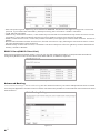
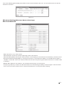
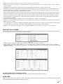
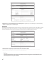
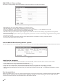
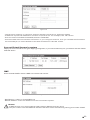
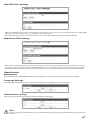
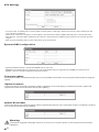
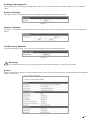
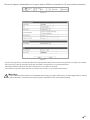
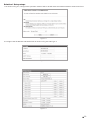
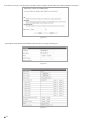
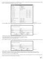
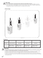
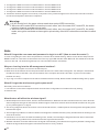
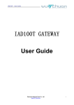
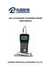
High-gain Wireless Outdoor AP
User Manual
Catalogue
Chapter 1 Product Intrduction
Brief Introduction......................................................................................1
Product Characteristics.............................................................................1
Installation Environment............................................................................1
BOM........................................................................................................1
Hardware description................................................................................2
Indicator...................................................................................................2
Rear-panel diagrammatic drawing..............................................................2
Chapter 2 Product installation
Hardware Connection...............................................................................3
Local Area Network setup..........................................................................5
Wireless network connection.....................................................................6
Chapter 3 AP Router operating mode setting
Login..........................................................................................................8
Wizard( Quick setting for Wizard)................................................................9
Operation Mode..........................................................................................9
Internet Settings.......................................................................................10
WAN......................................................................................................10
LAN.......................................................................................................12
DHCP Client(DHCP Client List)................................................................13
Advanced Routing..................................................................................13
Wireless Settings(Wireless Network Settings).........................................14
Wireless Network ...................................................................................14
Advanced Wireless configuration.............................................................15
Security(Security configuration)..............................................................16
Station List(Client List)...........................................................................18
Firewall...................................................................................................18
MAC/IP/Port filter...................................................................................18
Port transmission...................................................................................19
DMZ......................................................................................................20
System security setting...........................................................................21
Content Filter.........................................................................................21
Administrator.........................................................................................22
Management ..........................................................................................22
Firmware update....................................................................................23
Settings management.............................................................................24
Status....................................................................................................24
Statics...................................................................................................25
System Log............................................................................................25
Chapter 4 AP Client Router operating Mode Configuration
Login....................................................................................................25
Profile...................................................................................................25
Link Status............................................................................................26
Site Survey............................................................................................27
Chapter 5 AP Operation Mode Setting
Login....................................................................................................29
Point-to-point connection.......................................................................29
Distant bridge........................................................................................35
Point-to-Multipoint Bridge.......................................................................37
Chapter 1 Product Introduction
Brief Introduction
The BL-DA01 2.4 GHz high power outdoor AP provides effective solution to mobile users outdoor and users with wire
arrangement trouble, thus allowing you to surf Internet anywhere at any time. BL-DA01 frees users from the hassle of
wiring and installation environment, allows users to increase and allocate work stations at will.
BL-DA01 adopts integrated shell and is powered by POE. It supports multi-language WEB management, multiple
encryption methods and strategy control, thus making incomparable flexibility, convenience and security for the
installation. It adopts high gain antenna technology, the internal antenna(there is port for external antenna) can
achieve a stable transmission distance of 2 Km in unblocked environment.
BL-DA01 is a combination of wired router, wireless AP, wireless bridge, wireless relay and AP Client, it work as
a point-to-point, point to multi-point wireless bridge as well as wireless signal amplifier.
BL-DA01 is widely used the application:
- Wireless connection of video monitor
- WIFI coverage for LAN Internet of cooperations
- WIFI coverage for imformationization of rural areas
Product Characteristics
- Complies with IEEE 802.11g, IEEE 802.11b, IEEE 802.3, IEEE 802.3u standards.
- Wireless Data transfer rates up to 54Mbps.
- Supports multiple working mode and wireless mode.
- High output transmit and receive sensitivity optimized.
- Supports Passive POE power supply.
- Supports WDS mode
- Provides throughput monitor indicating the current wireless throughput
- Output transmit power adjustable
- Supports PPoE, static IP, dynamic IP Internet access.
- Built-in NAT and DHCP server supporting static IP address distributing.
- Supports configuration backup/restore and firmware upgrade.
- Integrated housing design, dust-proof, moisture-proof, water-proof and anti-UV
Installation Environment
- Working temperature: - 30℃~70℃
- Working humidity: 10%~90% RH,non-condensation
BOM
- Outdoor AP
- AC adapter (DC 15V)
- POE
- Cable
- Cable tie
- Quick installation guide
Notice: Should any accessory be missing or damage be found, please contact the local dealer immediately.
01
Hardware description
Indicator
Front-panel diagrammatic drawing
Power
LAN
1
2
SYS
Wireless Signal Strength
3
4
Figure 1-1
Judge from left to right side
Indicator
Status
Indication
Off
Power off
Power
LAN
SYS
On
Power on
Off
Port disconnected
On
Port connected
Glint
Data transmitted through port
Off
System processing abnormally
On
System process normally
No connection or lack of wireless signal in Client wireless mode
Wireless
Signal
Strength
Off
Operates in other modes except Client mode
On
Indicates signal strength in Client mode
Warning:
Wireless Signal Strength is only activated in Client wireless mode and 3 indicators indicate signal strength,otherwise they will
black out in other modes.
Rear-panel diagrammatic drawing
2
3
4
1
Figure 1-2
Judge from left to right side:
1 Antenna extending port: you can extend external antenna by this port
2 System reset button:Keep pressing the button for 5 seconds while power on, AP will reboot to default setting
3 System reset button:Keep pressing the button for 5 seconds while power on, AP will reboot to default setting
4 RJ 45 port: it is used as the upstream port to connect Internet or MAN(metropolitan area network) and works as the
POE power supply
Tips:
Ensure consistent power supply for this device before AP activated.
02
Chapter 2 Product installation
Hardware Connection
Please follow the steps below to install the device.
1.Connect each cable according to the following diagram
Connect to
extending
antenna
Indoor
Figure 2-1
2.Solder the lightning conductor on the pole and connect Mechanical lightning protection effectively. Then settle it on
the top floor of the building or other outdoor place, finally fasten the outdoor AP on the pole.
Lightning conductor
Lightning conductor
Cable ties
It is suggested to use a round bar steel with diameter of 60mm~110mm.
Figure 2-2
03
3. Final installation sketch is as follows:
Lightning conductor
best radiation
coverage range
Additional antenna
Figure 2-3
Caution during installation
1.Avoid electromagnetic interference (EMI) environment with radar station, converting station etc.
2.Ensure the lightning protection device grounding of the outdoor AP as well as its connected device(AP).
3.The cable that connect the outdoor device should be customized waterproof,At the same time, make sure that device of
both ends are grounded effectively.
4.The cable for the POE power supply and outdoor device shall be within the limit of 50 meters.
5.The built-in directional antenna has strict limitation to direction, the best radiation coverage range is: horizontal 60
degrees, vertical 60 degrees. Therefore the location should be planned well before setting up the pole.
6.For the scope outside effective signal coverage area of the built-in directional antenna, it can be solved by extending
additional antenna in the antenna extending port.
04
Local Area Network setup
The default LAN port IP address of this device is 192.168.16.1, default sub net mask is 255.255.255.0. They can be
modified according to actual need, this manual would present as default value. For Windows Vista or Windows 7
system, please follow the steps below to setup.
1.Click “Start→Control Panel→Network and Internet→Network and Sharing Center→Change adapter settings→
Local Area Connection” Select “Local Area Connection”, right-click it and select “Properties”
Figure 2-4
2.Select “Internet Protocol Version 4(TCP/IPv4)” and click “Properties”
Figure 2-5
05
3.Set IP address as 192.168.16.X(X should be a numeral between2 to 254), subnet mask as 255.255.255.0, then click
“OK” to return back the last page, click “OK” once again.
Figure 2-6
4.Set IP address as 192.168.16.X(X should be a numeral between2 to 254), sub net mask as 255.255.255.0, click
"OK" and return to last interface, click "OK" again
Wireless network connection
Default SSID of this device is: BL-HighPowerourAP65, for Windows7 system, please follow the steps below to connect
wireless network.
1.An icon of "
" will appear in the bottom right corner after installation of wireless card. click this icon.
Figure 2-7
06
2.Select the network you want to connect in network list, click"connect" .
Figure 2-8
3.You are required to input the correct password if you encrypted the connecting device. (default value is not encrypted)
Figure 2-9
It indicates successful access to wireless network
when "Connected"appear on the screen.
07
Chapter 3 AP Router operating mode setting
Wireless port. While connecting to WISP, the Wireless port works as a WAN port in AP Client mode. The Ethernet port
acts as a LAN port.
Login
1.Open the web browser,Input the default address: 192.168.16.1 in address bar, then press “Enter”
Figure 3-1
2.Input user name and password, default value are all “admin”, and then click “OK”.
Figure 3-2
3.Successful Web server login appears as follows
Figure 3-3
There are 6 setting items in AP Router(Wired router+AP) mode. You can configure relevant functions by selecting any of
each item, it will cover all item function in detail as follows.
08
Wizard( Quick setting for Wizard)
Click "Next" in quick Quick Set-up interface, you can configure the device with steps required
Figure 3-4
Operation Mode
It offers three basic Internet access modes for different users: AP mode, AP Route mode and AP Cilent Router
mode. Besides, it can be divided into various wireless modes in AP Internet access mode, such as Access Point,
Client, WDS point to point relay, WDS point to multipoint relay, WDS point to point bridge connection, WDS point
to multipoint bridge connection.
Figure 3-5
AP Mode
In Wireless access point (AP) mode, it constructs a self-centralized control network that operates as a mere AP, which
convert cable signal into wireless signals through connecting the network device ahead of it with cable.
AP Client
In this mode, not only does it have the standard wireless function of access point, but also it can act as a client to
link wireless hot spots, realizing the signal relay and amplification, thus extending the wireless network coverage.
WDS point to
point relay
By setting up two sets of AP as WDS Point to Point realy mode, it combines two seperate LAN as one united network
as well as realizes the signal relay and amplification through connecting two AP by wireless method, thus extending
the wireless network coverage.
WDS point to
multipoint relay
It is similar to WDS point to point mode, AP as the central accesss point, making a number of discrete remote
network join up.
WDS point to
point bridge
connection
Similarly, in this mode, compared with WDS point to multipoint relay, AP is identical with it except that it sends signal
to the device that connect with it only instead of any other client.
WDS point to
multipoint bridge
connection
Similarly, in this mode, compared with WDS point to multipoint relay, AP is identical with it except that it sends signal
to the device that connect with it only instead of any other client.
Wired router+
AP mode
In this mode, RJ45 ethernet port works as WAN connecting port, it can offer internet sharing for the outdoor wireless
client device through connecting indoor xDSL Modem or broadband access by cable.
Client Router
Mode
In this mode, RJ45 Ethernet port works as LAN port, AP works as client, it connects wireless hot spots, and then
connects the indoor PC or switch with cable to realize Internet sharing. this mode only serves for users of wired
connection and doesn’t send wireless signal to any other clients.
!
09
Except Access point mode, other modes all support plug and play, software configuration on WEB server is
unnecessary. other functions can be configured according to this manual.
Internet Settings
WAN
You can quickly configure AP with connection type provided by ISP in WAN configuration, enabling LAN computers to
share network service of ISP. All parameters are provided by ISP in this mode, please refer to ISP if any parameter is
undefined.
1.Please select "STATIC(fixed IP)" as follows when you get IP address, sub net mask, Gate way and DNS
server. please refer to ISP if any parameter is undefined.
Figure 3-6
-
IP Address: Static IP address offered by ISP
Sub Net Mask: Sub net mask offered by ISP
Default Gateway: input the gateway information offered by ISP
Primary DNS Server:input the DNS server address provided by ISP, DNS address differ from area
Secondary DNS Server: Input the spare DNS server address provided by ISP, DNS address differ from area
click "Apply" after configuration
2.Please select "DHCP(Auto config) " as follows if no IP parameters offered by ISP, the device will obtain the IP
address automatically from ISP
Figure 3-7
10
3.ISP offers "User Name" and "Password" under PPPoE mode, please select "PPPoE(xDSL)" in "WAN Connection
Type" as follows. please refer to ISP if any parameters is undefined.
Figure 3-8
- User Name: input the account provided by ISP. Configuration must be done. Consult the ISP if not clear.
- Password and Verify Password: input the password provided by ISP. Configuration must be done.
Consult the ISP if not clear.
- Operation Mode: Chose from three operation modes (Keep Alive, Dynamic demand, Manual demand)
- Always Connected: if this mode is selected, system will automatically connect after start. If the network is
disconnected by external factors, system will try to connect every 60 seconds till it is successful.
- Dynamic Demand: system will automatically connect when the LAN require access and automatically
disconnect when there is no access requirement in time set time. To those users who pay as you go is
suggested to select this connection method to save Internet fee.
- Manual Connection: Users have to dial to connect in this mode. They can connect or disconnect the Internet
by clicking "Connect" or "Disconnect".
MAC Clone
MAC Clone is applied under MAC address registration requirement of ISP to manage computer Mac address.
It is only required under special condition.
Figure 3-9
• Select: to "Enable" or "Disable" the function of MAC Clone.
• MAC Address:configure the WAN port MAC address of the device. If ISP offers a MAC Address and
requires MAC binding with MAC Address of router WAN port , just input the number in MAC Address bar.
• Fill my MAC: Click this button and clone the MAC address to the "MAC address" bar
Notice:
"MAC Clone" only applies in computers in LAN.
11
LAN
Select "Internet Settings>LAN"then you can configure IP address, Sub Net mask and DHCP of LAN port
LAN Setup
Figure 3-10
- Sub Net Mask: The default Sub Net Mask of this device is 255.255.255.0, it can be modified according to
actual need.
- LAN 2: Enable the LAN 2 of this device, then you need to configure the IP address and sub net mask of the
LAN 2
- LAN 2 IP Address: configure the second IP address of this device in LAN
- LAN 2 sub net mask: configure the second Sub Net Mask of this device in LAN.
- MAC address: the MAC address of this device in LAN, which is used to identify the LAN
DHCP server configuration
Figure 3-11
- DHCP Type: Select the server to realize automatic assignment of IP address to computer, otherwise select
"Disbale"
- Start/End IP address:Input the start and end IP address, the LAN(intranet) IP address assigned by DHCP is
between these two IP address.
- Sub Net Mask: configure the corresponding subnet mask according to the Start/End address.
- Primary/secondary DNS Server: optional. you can input the DNS Server offered by ISP
- Default Gateway: optional. Usually input the IP address of the LAN port. Default value: 192.168.16.1.
- Lease Time: T he valid time of IP address distributed by DHCP server to the intranet hosts (unit is second).
Default value is 86400 seconds, that is a day. Serve will not distribute this IP address to other hosts during
this period of time.
- Statically Assigned: used to assign IP address when DHCP automatically assign IP address.
- MAC: input the MAC of computers that require reserved static IP address, such as 00:0C:43:80:80:88
- IP address: input the reserved IP address to the appointed intranet hosts, such as 192.168.16.254.
12
Figure 3-12
- 802.11d Spanning tree: Spanning Tree defines in IEEE802.1D,which is a bridge to bridge link connection
protocol, it provides Path redundancy while preventing self-circulation. default is disable.
- LLTD: default is disable
- IGMP Proxy:enable this function, it will Inhibit layer multicast flood and effectively obtain and control user
information, thus reducing Network protocol news to deduct Internet load. default is disable
- UPNP: enable this function, router will provide automatic pot mapping for intranet P2P software. default is
disable.
- Router Advertisement:enable this function, Router will send or reply message to each other within certain
period to demonstrate their existence.
- PPPoE Relay:enable this function, it enables Local Area computer in Router gateway mode to dail PPPoE
directly. default is disable
DHCP Client(DHCP Client List)
Select"Internet Settings>DHCP Client " , then you can see the related information of computer with automatic IP
assigned by DHCP in LAN. such as Host name, MAC Address, IP Address, Expires in
Figure 3-13
Advanced Routing
Select Internet Settings > Advanced Routing,You can use this function if you want to add specified router to certain
host. Proper application of static router in network can deduct the problem of router selection and overload of router
data selection.
Figure 3-14
13
The current Routing table displays the default router and self-defined router rule. the self-defined rule can also be
deleted or canceled
Figure 3-15
Wireless Settings( Wireless Network Settings)
Wireless Network
Figure 3-16
-
Radio On/Off: turn on/ off the radio
Network Mode: select the wireless operating mode of this device
Network Name(SSID): identify the network name. it will display on the network list searched by wireless client.
Broadcast Network Name(SSID): to configure this device to broadcast to SSID or not, SSID will be hidden if
"disable" is selected. Client can communicate with the device by learning the SSID of this device. default value
is "Enable"
- BSSID: MAC address of the station, the wireless identification of access point.
- Frequency(Channel): channel for data transmission of transmitting media by wireless signal. channels differ
from country and area. please refer to "Advanced"setting for country and district setting.
14
You can also configure the High Throughput in 11n mode when network mode is 11b/g/n mixed mode or 11n only.
Figure 3-17
- Operating Mode: In Mixed mode, downward compatibility of 802.11n wireless client connection, but the
throughput will be affected. in GF(Green Field)mode, it will affect downward compatibility and system
security, but it can reach High Throughput data transmission. default value is Mixed mode
- Channel BandWidth: you can either select 20 or 20/40. default is 20/40
- Guard Interval: you can either select Long or Auto. default value is Auto.
- MCS: You may select the MCS value from 0 to 32. The default MCS is Auto.
- Reverse Direction Grant(RDG): you can either disable or enable this function.
- Extension Channel: configure the frequency with related extension channel.
- Space Time Block Coding(STBC):you can either select disable or enable, default value is disable.
- Aggregation MSDU (A-MSDU): Frame aggregation,defalut value is disable.
- Auto Block ACK:to realize Polymerization exchange sequence and boost transmission rate. default value is
enable
- Decline BA Request: it can boost the transmission rate. default value is disable
Advanced Wireless configuration
Select "Wireless Settings > Advanced", then you can configure advanced wireless setting. such as Beacon Interval,
TX Power etc.
Notice: it is suggested to keep the default value for general users.
Figure 3-18
15
- BG Protection Mode: default is Auto. you may select On, Off, or Auto.
- Beacon Interval: to configure the wireless beacon frame sending interval of wireless basic station, default
value is 100ms.
- Data Beacon Rate(DTM): designate the transmitting beacon interval, default value is 1ms
- Fragment Threshold: fragment threshold is determined before package transmission. its data decides the
byte of fragment. configure proper fragment value will decrease the re-transmitting times, thus improving
the wireless network function. default value is 2346.
- RTS Threshold:proper transfer request mechanism can avoid two stations fall in one access point range, the
hidden node differs in each range can also be avoided. RTS Threshold determines the package size of RTS
- TX Power: the TX power to SSID. set it as 50 it will send half power; default value is 100, all power sent out.
- Short Preamble : select disable, it will adopt Long lead frame; select enable, it will adopt Short lead frame.
default value is disable.
- Short Slot: default value is enable. you can also disable it. "enable" is suggested.
- TX Burst: it bears MAC address features, which will improve the equity of wireless network TCP transmission.
default value is enable.
- Pkt_Aggregate: to combine multiple package by aggregate technology, enhancing the system of data packet
to arrive destination by LAN. thus improving transmission rate. default value is enable.
- Country code:select according to country and area. default value is None. IE. adopts 1~14 channels.
Wi-Fi Multimedia(WMM)
To ensure priority processing of different wireless data type by configuring the Wi-Fi multimedia QoS ability,thus
ensuring the High quality transmission of data package.
Figure 3-19
- WMM Capable: Enable or disable the WMM function. default value is enable.
- DLS Capable: the Direct Link capability. you can either select enable or disable. default value is disable.
- WMM Parameters:click"WMM Configuration",the WMM Parameters of Access Point configuration page will
pop out as follows:
Figure 3-20
Security(Security configuration)
Select Wireless Settings > Security,then you can configure the wireless network security
OPEN WEP
WEP encryption way is the earliest encryption technology, which adopts 64/128 bite key to encrypt the data transmission.
take OPEN WEP as an example to explain as follows:
16
Figure 3-21
- Default Key:select the required key from 4 default keys
- WEP Keys 1~4: Input the password. when selecting "Hex",Legal key is 10 or 26 Hex figure. when selecting
"ASCII", Legal Key is 5 or 13 ASCII figure.
WPA-PSK
WPA-PSK is a new standardized encryption technology, which providing more powerful encryption than WEP, it includes
two encryption ways, TKIP or AES, Moreover, it can also automatically change pass phrase to prevent Hacker attack
effectively, making it the most common encryption way at the moment. take WPA-PSK as an example.
Figure 3-22
- WPA Algorithms: select one of the encryption way, either AES or TKIP.
- Pass Phrase: to set pass phrase, which shall be a 8~63 ASCII character or 64 hexadecimal numeral
- Key Renewal Internal:input the renewal interval of pass phrase.
Notice:
When select OPEN WEB or WPA as the security mode, while “WPA algorithms” as the TKIP TKIPAES 11N, the
maximum data transmission rate would drop as 54Mbps therefore it is suggested to select WPA safety mode
with AES algorithms to encrypt the wireless.
17
Access Policy--based on MAC
Through configuring allow or reject the selected MAC Address client to access under the same SSID. thus
realizing control of wireless access.
Figure 3-23
- Function: If Disable is selected, visit strategy function would be disabled. Visit control to the wireless devices
in the MAC list will be canceled. If Allow is selected, the added MAC address can access the router while the
unadded address can not, and vice versa if Reject is selected.
- New add: input the MAC address of the wireless clients to be restricted in the text box, and then click Apply.
- Del: click the "Del" button on the MAC list to delete the corresponding MAC, and then click Apply. It will take
affect after reboot.
Application::
Only the clients whose MAC address is 00:A1:B0:80:80 are allowed to connect, and other clients are all rejected.
1. Log into WEB. Open wireless network setting and select Security setting.
2. Select Allow in the drop menu of the visit strategy function.
3. Input 00:A1:B0:80:80:00 in the new added text box.
4. Click Apply button to reboot the device.
5. It takes about 60 seconds for the machine to start. Except that the clients whose MAC is 00:A1:B0:80:80:00
can access, other clients are rejected.
Station List( Client List)
Select"Wireless setting >Client list " , then you can check the relevant information of wireless clients that
connected at present.
Figure 3-24
Firewall
MAC/IP/Por t filter
Select Firewall>MAC/IP/Port filter, and control the authority of the client to access WAN according to
MAC/IP/Port.
Basic Settings
Open Basic Settings and select a default strategy (accept or reject), which means unmatched data would be accepted
or rejected. Click Apply to summit.
Figure 3-25
18
MAC/IP/Por t filter setting
Fill out the corresponding options and filtering rules according to your personal needs.
Figure 3-26
-
MAC address: fill in the MAC address you want to define.
Dest IP Address:Input the dest IP address you want to filter
Source IP Address: Input the source IP address you want to filter, i.e. the IP address of LAN
Protocol:select the protocol of the controlled data packet
Dest Port Range:Input the dest port range that you want to control. the starting range shall not be greater
than the end range.
- Source Port Range:Iput he Source port range that you want to control. the starting range shall not be greater
than the end range.
- Action: the definition should be Accept or Dropped, which should be contrary to default value
- Comment:the description of the rules.
Current MAC/IP/Port filtering rules in system
The list displays the current filtering rules, you can select the one you want to delete and click "Delete Selected" button
Figure 3-27
Application example:
- Host with IP of 192.168.16.146 is forbidden to access WLAN, while hosts with other IP can access WLAN.
1.Login WEB, open the fire wall>MAC/IP/Port filtering
2.Select enable in the drop-down list of MAC/IP/Port flittering
3.In default rule configuration: the data packets which does not complies with rules will be received
4.Input 192.168.1.146 in the IP address bar of MAC/IP/Port flittering rule, then click "Apply" to submit
5.After starting finished(around 60 seconds), the host with IP address of 192.168.16.146 will be forbidden to access
WLAN
Port transmission
Select "Firewall> Port " , then it can perform port mapping,configure virtual server, establish mapping between WAN
Port IP address, external port and LAN server IP address, internal port, thus realizing the service of WLAN users
access LAN intranet server, such as Web server, Email and FTP etc.
19
Figure 3-28
-
Virtual Server settings: to configure enable or disable virtual server, default is disable
IP Address:Input the IP address for intranet of virtual server. For example,192.168.16.254
Protocol:select TCP/UDP/TCP&UDP,default is TCP&UDP
Comment: add relevant comment information. if you configure as above, then you can add the information
as:access 80 port, it will be shifted to host with IP address of 192.168.16.254.
Current Virtual Servers in system
Display the current virtual servers (port mapping)configuration, if you need to delete any rule, just select it and click "Delete
Selected" button.
Figure 3-29
DMZ
Select Firewall>DMZ to divide a DMZ into intranet and Internet.
Figure 3-30
- DMZ Setting: enable or forbid DMZ host
- DMZ IP Address: enter the IP address of the host shown to public.
Notice:
- If DMZ function is on, the host will be totally visible to WAN and security is low.
- The port number to access DMZ host should be the same as the actual working serving port number of DMZ.
20
System security setting
Select "Firewall>System security" setting to configure the system security.
Figure 3-31
-
Remote management (via WAN): enable or disable distant administration according to actual situation.
Ping from WAN Filter: enable to filter the PING packet of the WAN.
Block Port Scan: enable to block port scan from WAN.
Block SYN Flood: enable to safeguard against malicious attack from WAN.
SPI Firewall: enable to cheak the data package status from WAN to prevent illegal invasion.
Notice:
Enabling corresponding function, such as SPI Fire wall, may cause default strategy (IP/MAC/PORT filter) to
failure.
Content Filter
Select Firewall>Content Filter, and web sites can be filtered as required.
Web Content Filter
Supports 3 types of filters.
Figure 3-32
- Proxy: filtering webs forwarded by proxies.
- Java: filtering webs contain Java.
- ActiveX: filtering webs contain ActiveX.
21
Web URL Filter Settings
Figure 3-33
- New added URL filtering rules: input URL and click Add to forbid access to certain web sites. new added URL
filtering rules will display in the current URL filtering rules list.
- Delete URL filtering rules: Select the rules in the current URL filtering rules list and click Delete.
Webs Hosts Filter Settings
Figure 3-34
- New added webs hosts filtering rules: input the key words of the host names and click Add button to forbid
access to certain web sites. The new added filtering rules will display in the current host filtering rules list.
- Delete Webs Host Filtering Rules: Select the rules in the current host filtering rules list and select Delete.
Administrator
Management
Select Administrator> Management to change language, account and password, and system time setting.
Language Settings
Select English, simplified Chinese or traditional Chinese and click Apply to change language.
Figure 3-35
Administrator settings
Input the Account and Password that you want to change, click"Apply"
Figure 3-36
Tips:
If you forget Account and password, you can reset the device by pressing the Reset button on the panel for 5
second.
22
NTP Settings
Figure 3-37
- Current Time: it displays the current time of the system. click"Sync with host" button, then the device will
sync the time with host.
- Time Zone: select the location of the system. Chinese users select (GMT+08:00)China, China HK" time.
- NTP Server: Input the URL address of the server. Chinese users please select the server of Asian-Pacific
region.
- NTP synchronization(hours): the interval of sync time server.
Dynamic DNS configuration
Figure 3-38
- Dynamic DNS Provider: select the DDNS Server you use.
- DDNS Account/Password: Input the Account and Password you registered in DDNS provider service.
- DDNS: Input the registered effective domain name
Fir mware update
Select Administrator >Update Firmware, then you can update the firmware, thus the system will activate the program
update
Update fir mware
Click"View" button and select the latest firmware update file, then click"Apply" to submit the request, system will
update the firmware and reboot the device after updating.
Figure 3-39
Update Bootloader
Click"View" button and select the latest system update bootloader file, then click"Apply" button to submit the request,
thus system bootloader will be updated.
Figure 3-40
War ning:
To avoid fail upgrade or damage to device, be sure not to cut off the power or disconnect the Internet while
upgrading.
23
Settings management
Select "Administrator > Settings management". then you can export backup from CONFIG.SYS or reboot to default
value
Expor t Settings
Click Export button to export the current configuration to designated location for back up.
Figure 3-41
Impor t settings:
Click"View", select the file exported before, and then press Import button, system will reboot and return to configuration
before.
Figure 3-42
Load Factor y Defaults
Click "Load Default" button, then it will recover all setting to factory defaults and reboot.
Figure 3-43
War ning:
It is suggested to save the current configuration before Import settings or Load Factory defaults
Status
Select "Administrator>Status" to check the SDK version of the system, System Up Time, System Platform and Operation
Mode, and LAN info.
Figure 3-44
24
Statics
Select Administrator>Statics to display the memory status of current system, data package sent or received by WLAN,
LAN and WAN
Figure 3-45
System Log
Select Administrator>System Log info to check system log and learn the events of the router through local inquiry or distant
monitor.
Figure 3-46
Chapter 4 AP Client Router operating Mode Configuration
In AP mode, this device allows multiple wireless clients to access wireless LAN through WiFi. Ethernet port can
also be divided into multiple wireless modes, such as Access point, Client, WDS point to point relay, WDS point to
multi-point relay, WDS point to point bridge and WDS point to multi-point bridge.
Login
Log in the WEB server of AP in AP Client Route mode; except options related to AP Route Mode on left menu, other options
should be the same as those in AP Router mode. Please refer to Chapter 3 for setting. Only the typical application of
wireless network configuration are introduced here.
Profile
Then you can configure on "Wireless Settings > Profile" configuration web server.
Figure 4-1
25
- Add:Click add button, configure the binding connection between this device and wireless base station in the pop-up
interface as the following page(screen shot:4-2)
- Delete:Select the configured connection in Profile List, then click the delete button to remove this configuration.
- Edit:Select the configured connection in Profile List, then click the Edit button to Edit this configuration
- Activate:Select the configured connection in Profile List, then click the Activate button to activate this configuration.
Once the activation succeed, the connection between this device and wireless base station is set up, a green icon
will display on the screen.If the activation failed, then a red icon will display and this device can not set up connection
with wireless base station.
Figure 4-2
Notice:
You can not perform connection unless activating the binding connection. More binding connection can be
set up, but only one can be activated to perform connection
Link Status
Select Wireless Settings > Link Status then you can check the connection status information of this device with
wireless base station.
Figure 4-3
26
Site Sur vey
Select"wireless setting">Site Survey,then you can scan the wireless base stations. then select one
base station to connect or binding.
Figure 4-4
-
SSID:displays the current SSID of AP.
BSSID: displays the current BSSIP of AP, generally it is the MAC address of AP.
RSSID:displays the signal strength received from current AP.
Channel:displays the wireless data transmission channel of current AP.
Encryption:displays the encryption way of current AP.
Authentication:displays the authentication of current AP.
Network type : displays the network type of current AP.
Connect:Select the base station you want to connect in the scanned list, then click connect button, a page will
pop-up as 4-6 screen shot shows for connection and authentication.
- Rescan:click rescan button, it will rescan the base station.
- Add Profile:select the connecting base station in scanned list,then click Add Profile button, a pape will pop-up
as screen shot 4-8 shows to configure binding.
Figure 4-5
- SSID: the SSID of base station. generally it is set as default with automatic run of system.
- Security Policy(Security Mode):the authentication of connection base station. generally it is set as default
with automatic run of system
- WPA Algorithms:the encryption way of base station. generally it is set as default with automatic run of system
- Pass phrase:Input the pass phrase of wireless connection in connected base station.
Notice:
You can click "Apply" button to submit the submit the configuration if the connected base station doesn't
configure with security mode.
27
There will display a handshake icon in green before SSID as screenshot 4-6 if connected successfully.
Figure 4-6
Figure 4-7
-
System Configuration:For SSI and Network type please keep the automatic configuration of system as default.
Security Policy(Security Mode):keep the automatic configuration of system as default.
WPA Algorithms:keep the automatic configuration of system as default.
Pass Phrase:Input the pass phrase of wireless connection in connected base station.
Warning:
- If the connected basic station is not equipped with security encryption mechanism, click the Apply button to submit.
- After submission, activate the security encryption mechanism in the online binding setting.
28
Chapter 5 AP Operation Mode Setting
In AP mode, this device allows multiple wireless clients to access wireless LAN through WiFi. Ethernet port can
also be divided into multiple wireless modes, such as Access point, Client, WDS point to point relay, WDS point to
multi-point relay, WDS point to point bridge and WDS point to multi-point bridge. therefore, the device works in AP
mode is widely applied in various wireless transmission network.
Login
Log in the WEB server of AP in AP mode; except options related to WAN (such as WAN and Firewall), other options
should be the same as those in AP Router mode. Please refer to Chapter 3 for setting. Only the typical application of
several wireless modes in AP mode are introduced here.
Point-to-point connection
AP2
Power
LAN
SYS
Wireless
Signal
Strength
Internet
Figure 5-1
Solutions
AP1 operation mode
AP1 wireless mode
AP2 operation mode
AP2 wireless mode
Solution 1
AP
AP access point
AP
AP client mode
Solution 2
AP
WDS point-to-point
bridge or WDS
repeater mode
AP
WDS point-to-point
bridge or WDS
repeater mode
War ning:
- Solution 2 require AP1 and AP2 should have WDS function.
- Comparison of WDS point-to-point repeater and WDS point-to-point bridge: the former is accessible to both
wired and wireless clients while the latter is accessible to wired clients only.
29
Solution 1 Setup steps
1.As shown in Fig 5-2, configure the operation mode of AP1 to be AP mode and wireless mode to be Access Point.
Figure 5-2
2.Configure the IP address and SSID of AP as shown in Fig 5-3 and Fig 5-4:
Figure 5-3
Figure 5-4
30
3.As shown in Fig 5-5, configure the operation mode of AP2 to be AP mode and wireless mode to be Client.
Figure 5-5
4.Configure the IP address and SSID of AP2 as shown in Fig 5-6 and Fig 5-7.
Figure 5-6
Figure 5-7
31
5.Configure the connection of AP2 and AP1.
1.As shown in Fig 5-8, Select Wireless Setting>AP Client, select AP1 in the list of client scanning results, and click
"Connect".
B
A
C
Figure 5-8
2.Wireless connection certification
D
Figure 5-9
3.A green sign of handshake will display if connection is successful.
A green sign of
handshake will
display if connection
is successful.
Figure 5-10
4.Check the connectivity of two network segments. Computers of any network segments can access the
Internet and share documents and printers with other computers
32
Solutions 2 Setup steps
1.As shown in Fig 5-11, configure the operation mode of AP1 to be AP mode and wireless mode to be Bridge
(Point-to-Point).
Figure 5-11
2.In WEB Server of AP1,select wireless Settings> Basic, set AP1 wireless channel as 11 and note
down SSID of AP1. as shown in Fig 5-12.
Figure 5-12
3.As shown in Fig 5-13, configure the operation mode of AP2 to be AP mode and wireless mode to be Bridge
(Point to Point).
Figure 5-13
33
4.Select Wireless Settings>Basic in the WEB server of AP2, configure the wireless operation channel of AP2
to be 11, and record the BSSID of each AP2 on paper.
Figure 5-14
5.In the WEB server of AP2, select Wireless Settings>WDS to do the relative setting as shown in Fig 5-15.
Figure 5-15
-
Entity mode: select entity mode in the drop menu.
Encryption methods: select encryption methods in the drop menu.
Encryption private key: set the certification key of WDS connection.
MAC of wireless AP: enter the SSID of AP1.
6.In the WEB server of AP1, select Wireless Network Connection>WDS to do the relative setting as shown in Fig 5-16
Figure 5-16
-
Entity mode: select entity mode in the drop menu, with the same setting as in AP1.
Encryption methods: select encryption methods in the drop menu, with the same setting as in AP1.
Encryption private key: set the certification key of WDS connection, with the same setting as in AP1.
MAC of wireless AP: enter the SSID of AP2.
7.Check the connectivity of two network segments. Computers of any network segments can access the Internet and
share documents and printers with other computers
34
War ning:
1. AP1 and AP2 must be in the same subnet mask when setup WDS connection
2. AP1 and AP2 must be assigned the same wireless operation channel when setup WDS connection.
3. In the step 5 and 6 of setting WDS connection of AP1 and AP2, entity mode, encryption methods and
encryption private key of both APs must be consistent with each other.
Distant bridge
APn
AP2
AP3
AP1
...
...
Figure 5-17
Solutions
AP1 wireless mode
AP2 wireless mode
AP3 wireless mode
AP n wireless mode
Solution 1
AP access point
AP client
AP client
AP client
Solution 2
WDS point-to-point
bridge or WDS
repeater mode
WDS point-to-point
bridge or WDS
repeater mode
WDS point-to-point
bridge or WDS
repeater mode
WDS point-to-point
bridge or WDS
repeater mode
War ning:
1. Scheme 2 requires all AP be equipped with WDS function and AP2 and AP3 be connected with network cable.
Likewise, AP4 and AP5 should also be connected with network cable.
2. In Scheme 1, AP2 and AP3 can also be connected without network cable, and the same with AP4 and AP5.
However, devices communicate in semi-duplex mode, bandwith will reduce as devices increase.
3. Comparison between the connection of WDS and point-to-point repeater and the connection of WDS and
point-to-point bridge: the former is accessible to both wired and wireless clients while the latter is accessible
to wired client only.
35
Distant transit solution 1 Setting procedures
1.Configure the operating mode and wireless mode of each AP as shown in solution 1.
2.Configure the IP address and SSID of each AP according to the following table.
AP 1
IP Address 192.168.16.10
SSID
OutdoorAP01
AP 2
192.168.16.11
OutdoorAP02
AP 3
192.168.16.12
OutdoorAP03
...
AP n
...
192.168.16.18
...
OutdoorAP08
3.Configure the connection of AP2 and AP1 in the WEB server of AP2
4.Configure the connection of AP3 and AP2 in the WEB server of AP3. If AP2 and AP3 are connected by network cable,
configuration of connection between AP3 and AP2 is not required
5.Repeat step 3 and 4 in the following setting.
6.Check the network segment connectivity. Computers of any network segment can access the Internet and share
documents and printers with other computers.
Distant transit solution 2 Setting procedures
1.Configure the operating mode and wireless mode of each AP as shown in solution 2.
2.Configure the IP address, SSID and wireless operating channel of each AP, and record the BSSID of each AP on
paper.
AP 1
IP Address 192.168.16.10
SSID
Channel
OutdoorAP01
Ch11
AP 2
192.168.16.11
AP 3
192.168.16.12
OutdoorAP02
OutdoorAP03
Ch11
Ch11
...
AP n
...
192.168.16.18
...
OutdoorAP08
Ch11
Ch11
3. Configure WDS connection of AP1 and AP2 in AP1 WEB server
4. Configure WDS connection of AP2 and AP1 in AP2 web server; AP2 and AP3 are connected by network cable.
5. Repeat step 3 and 4 in the following setting.
6. Check the network segment connectivity. Computers of any network segment can access the Internet and share
documents and printers with other computers.
War ning:
1.All AP should be in the same subnet mask when setup WDS connection.
2.When two APs make WDS connection to each other, as in the case of AP1 and AP2, the same
wireless channel must be set manually.
3.When two APs make WDS connection to each other, as in the case of AP1 and AP2, the entity
mode, encryption methods and encryption private key of both APs should be consistent to
each other.
36
Point-to-Multipoint Bridge
AP2
Power
LAN
SYS
Wireless
Signal
Strength
AP3
Power
LAN
SYS
Wireless
Signal
Strength
AP1
AP4
Power
LAN
SYS
Wireless
Signal
Strength
Figure 5-18
Solutions
Solution 1
AP1 wireless mode
AP2 wireless mode
AP3 wireless mode
AP4 wireless mode
AP access point
AP client mode
AP client mode
AP client mode
point-to-point WDS
bridge or repeater
point-to-point WDS
bridge or repeater
point-to-point WDS
bridge or repeater
point-to-multipoint
Solution 2 WDS bridge or repeater
War ning:
1. All APs in Solution 2 are required to have WDS function, and one can only connect to four at most.
2. Given that devices communicate in semi-duplex mode, the bandwidth of Solution1 and 2 will decline as
devices increase
3. Comparison between WDS point-to-point repeater and WDS point-to-point bridge: the former is accessiblel
to both wired and wierless clients while the latter is accessible to wired clients only.
37
Point-to-point bridge solution 1 setting procedures
1.Configure the operating mode and wireless mode of each AP as shown in solution 1.
2.Configure the IP address and SSID of each AP according to the following table.
AP 1
IP Address 192.168.16.10
SSID
OutdoorAP01
AP 3
AP 2
192.168.16.11
192.168.16.12
OutdoorAP02
OutdoorAP03
...
AP n
...
192.168.16.18
...
OutdoorAP08
3. Configure the connection of AP2 and AP1 in the WEB server of AP2
4. Configure the connection of AP3 and AP1 in the WEB server of AP3.
5. Repeat step 3 and 4 in the following setting.
6. Check the network segment connectivity. Computers of any network segment can access the Internet and share
documents and printers with other computers.
Distant transit solution 2 Setting procedures
1. Configure the operating mode and wireless mode of each AP as shown in solution 2.
2 . Configure the IP address, SSID and wireless operating channel of each AP, and record the BSSID of each AP on paper.
AP 1
IP Address 192.168.16.10
SSID
Channel
OutdoorAP01
Ch11
AP 3
AP 2
192.168.16.11
192.168.16.12
OutdoorAP02
OutdoorAP03
Ch11
Ch11
...
AP n
...
192.168.16.18
...
OutdoorAP08
Ch11
Ch11
3.As shown in figure 5-33, configure the WDS connection between AP1 and AP2, AP3, AP4, and AP5 in the WEB server.
Figure 5-19
-
Entity mode: select entity mode in the drop menu.
Encryption methods: select encryption methods in the drop menu.
Encryption private key: set the certification key of WDS connection.
From the top to the bottom, a section of entity mode, encryption methods and encryption private key
correspond one AP
MAC address of wireless AP: from the top to the bottom, input the BSSID of AP1, AP2, AP3, AP4 and AP5
accordingly.
38
4. Configure the WDS connection of AP2 and AP1 in the AP2 WEB server.
5. Configure the WDS connection of AP3 and AP1 in the AP3 WEB server.
6. Configure the WDS connection of AP4 and AP1 in the AP4 WEB server.
7. Configure the WDS connection of AP5 and AP1 in the AP5 WEB server.
8. Check the network segment connectivity. Computers of any network segment can access the Internet and share
documents and printers with other computers.
War ning:
1. All AP should be in the same subnet mask when setup WDS connection.
2. When two APs make WDS connection to each other, as in the case of AP1 and AP2, the same
wireless channel must be set manually.
3. When two APs make WDS connection to each other, as in the case of AP1 and AP2, the entity
mode, encryption methods and encryption private key of both APs should be consistent to each
other.
FAQ:
What if I forgot the user name and password to login in to AP? (How to reset the router?)
In case of forgetting the user name and password, reset the AP to default setting. Switch on the device and press the
RESET button for 5 seconds. AP will reboot when the very right LED indicator flash.NOTICE: The default IP of AP will
return to 192.168.1.X network segment (X is a round number between 2 and 253).
Why can I not log in to the AP management interface?
1. Make sure the computer connects to the AP LAN port.
2. Make sure the IP address of the computer and the AP are in the same network segment. For example. if the default
IP address of AP is 192.168.1.254, the IP address of the computer should be 192.168.1.X (X is a round number
between 2 to 253)
3. Try to log in on other computers.If the above methods still cannot help, Reset the AP to default setting and try again.
What if I forget the wireless encryption password?
Generally, there are two solutions:
1. Use cable to connect the computer and AP and check the configurations of wireless security setting.
2. Reset the AP.
What factors will affect the wireless signal?
1. WLAN adopts microwave transit, which is weak at diffraction. Walls are the main obstacles at home, which absorbs
electromagnetic strength as well as block wireless signal. Therefore wireless devices behind the walls can only pick
up very weak signal or no signal.
2. The strong magnetic field of microwave ovens, bluetooth devices, cordless phones and refrigrators will greatly affect
the wireless signal.
3. There might be problems of channel collisions and signals crosstalk caused by many wireless devices working in the
same environment
4. Interference source such as radio transmitting tower, welder, tram and high-voltage transformer within 100 meters
would cause strong interference to both the wireless signal and the devices.
5. Weather situation could also affect when the signal is transmitting. Thunderstorm and gloomy weather could greatly
weaken the signal while the signal could transmit further in sunny weather.
39
Why can the computer not connect to the Internet while wireless signals can be found?
1. Make sure the name of the wireless signals are the same as the SSID in AP setting.
2. Check the strength of the of the wireless signal. If the signal is weak, it will be better to adjust the placement of AP or to
make connection in short distance.
3. Check whether the AP is encrypted. If it is, make sure both the encryption settings of wireless card and AP are the
same.
4. Consult the computer or wireless card manufacturer for further guidance.
5. If the above advises could not solve the problem, try to reset the AP.
Why can the device not be connected via wireless while having no problem with cable?
Generally, if wired connection is normal, it means the configuration of AP is correct. Try to solve the problems as
suggested below:
1. Check the connectivity between wireless card and AP, which means check whether the computer can log in to the AP
management interface via wireless.
2. Make sure the computer is connected to the correct AP. (Judge from the SSID)
3. Check the correction of the IP address, gateway and DNS server address in wireless network connection.
4. Check whether the filter is enabled in AP security setting.
Why can the web page not be opened, but the QQ work well?
1. Check the correction of the DNS server address in network connection.
2. Make sure browser never dial to connect and no proxy is set.
3. Try another browser (Firefox).
How to improve the quality of signal transmission?
1. Choose a optimal location for AP. The requirement are as follows:
a) The location should be relatively high so that the radiation can go down. Avoid obstacles and blind area.
b) Let the signal go through as less walls as possible. It is best to make the wireless client and AP visible to each other.
2. Change channel to reduce radio crosstalk. It is better to have 5 or more radio signal channels between the user's
channel and others'.
3. Reduce the interference of domestic appliances so that the signal is unimpeded. Wireless AP should be placed away
from the above appliances.
4. If the AP antenna is removable, wireless signal can be strengthen by changing the antenna.
40