1
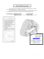
QTS
OWNERS MANUAL
GENIE S-60 and S-65
Rev 030109
Foreword
This manual contains safety, operation, maintenance, and adjustment information. The
procedures are designed to provide the best performance of the machine in an effective
and economical way. In order to obtain it, remember the next basic rules.
•
This manual should be stored in the operator’s compartment of any
machine where this attachment is used.
•
Before inspection, maintenance, or operating the QTS, read and
understand this manual completely.
•
Since all of the explanations in this manual may not be thoroughly
understood at first, repeat reading it until abilities as an operator are
obtained and developed for proper operation.
•
Further abilities as an operator outside of descriptions in this manual can
be obtained from experience during normal operations and under proper
supervision.
Because of continuing improvement and advancement of product design, the shape of the
attachment in the illustrations may be partly different from your machine. Whenever a
question arises regarding your machine, or this publication, please consult your local
Loegering dealer or Loegering Mfg. at 701-347-5441 for the latest information.
2
CONTENTS
-Serial Number Location
-Safety information:
Section 1-1
Section 1-2
Section 1-3
Section 1-4
-Nomenclature:
-Installation:
Section 2
Section 2-1
General Safety
Safe Operation
Safe Maintenance
Safety Symbols
Installing the QTS: Safety
Mounting the Right Front
Hammer Limiter Bracket
Section 2-2 Mounting the Left Front
Hammer Limiter Bracket
Section 2-3 Wheel Spacer Installation
Section 2-4 Wheel Spacer Installation
Section 2-5 Mounting the Rear
Hammer Limiter Brackets
Section 2-6 Installing the QTS
-Inspection and Maintenance:
Section 3-1 Inspecting the QTS
Section 3-2 Regular Maintenance
Section 3-3 Checking Track Tension
Section 3-4 Adjusting Track Tension
-Track Replacement
-QTS Parts 9-Bolt
-QTS Parts 9-Bolt Drawings
-QTS Parts 10-Bolt
-QTS Parts 10-Bolt Drawings
-QTS Torque Specifications
-MSDS Information
-Warranty Information
Page 4
Page 5
Page 6
Page 7
Page 7
Page 8
Page 9
Page 10
Page 10
Page 11
Page 11
Page 11
Page 11
Page 12
Page 13
Page 14
Page 14
Page 14
Page 15
Page 15
Page 16-19
Page 20-21
Page 22-23
Page 24-25
Page 26-27
Page 28
Page 29-33
Page 34-36
Rev 030109
Serial Number Location
Always provide the serial number of your QTS when ordering parts, requesting
service, requesting warranty, or any other information.
The serial number plate is located on top of the frame near the hub. Please record
the serial numbers in the space provided and on the warranty registration card.
Serial Numbers: Right Front QTS________ Left Front QTS ________
Right Rear QTS_________ Left Rear QTS_________
15514 37th St SE
Casselton, ND58012
800-373-5441
www.loegering.com
Model #: xxxxxx
Serial #: 1x-xxxxxx-xxx
Date of Mfg: xx-xx (MM-YY)
Weight (lbs.): xxxx
Capacity: xxxxxxxxx
4
SAFETY INFORMATION
We offer you basic and important rules and precautions for safe operation.
Read, understand, and observe them before starting operation. This is the most essential
way to prevent accidents.
Wrong operation, inspection, or maintenance can cause personal injury or death.
We have made every effort for you to prevent accidents during operation, however, we
cannot be held responsible for predicting every kind of danger in all operating conditions.
It is the owner or user of the machine who is responsible for ALWAYS paying attention
to operate the machine; as well as reading and understanding this manual enough to
obtain the essential knowledge and skills fundamental to correct machine operation.
Throughout this manual and on the QTS, precautions are provided with
marks and
classified by the words “Danger”, “Warning”, and “Caution” according to their extent
of danger.
The classification is as follows:
DANGER: indicates an imminently hazardous situation which, if not
avoided, will cause death.
WARNING: indicates a potentially hazardous situation which, if not
avoided could result in death or serious injury.
CAUTION: indicates a potentially hazardous situation which, if not
avoided, could result in minor or moderate injury. It may also be used to alert
against possible damage to the machine and its components.
WARNING
•
•
•
•
•
BEFORE inspection, operation, or maintenance of the QTS, be sure to
read and understand this manual.
Incorrect operation or maintenance of the machine can cause an accident
and serious injury or death.
Keep this manual on hand during operation so that you can immediately
consult it when necessary. If it should be missing or damaged, a new
manual can be downloaded from our website at www.loegering.com under
the QTS section.
There are various kinds of federal, state, and local regulations that effect
construction and industrial machinery. Since the regulations are subject to
change, and differ from one locale to another, it is impossible for us to
provide such information in this manual. It is the responsibility of the
owner or user to be familiar with the regulations.
Specifications and materials of the QTS are subject to change without any
obligation on the part of the manufacturer.
5
SAFETY
SAFETY TIPS
This section explains tips which you will find throughout this manual and on the QTS Track
System. Periodically check labels and plates containing those tips for damage. If they are
damaged, clean or replace them. For replacement, contact Loegering.
1-1 GENERAL
OBSERVE THE BASICS FOR SAFE
AND EFFECTIVE OPERATION.
The operator’s knowledge, skills, and
experience are the most important to
utilize the machine and QTS. Therefore,
be sure to understand operation procedures
and to take necessary training.
OPERATOR SHOULD BE
QUALIFIED.
Only qualified operators should operate
the machine, and those operators should
only do so when physically and mentally
alert.
The operator should be familiar with the
hazards and necessary safety measures
unique to the operation of QTS.
READ AND UNDERSTAND THE
INSTRUCTIONS AND WARNINGS.
Remember that the safety tips that we
provide cannot cover every kind of
danger that you may encounter during
operation.
WEAR PROPER WORKING
CLOTHES.
Wear working clothes that fit closely.
Avoid loose jackets, shirt sleeves, rings,
and other jewelry that may get caught in
moving parts of the QTS. Always wear
protective items such as hard hats, safety
glasses, and ear protection as required.
PERFORM “WALK-AROUND”
INSPECTION.
Walk around the machine to check for
any safety concerns before operation of
the machine.
PERFORM SYSTEM CHECK.
This manual, plates, and labels on the
machine contain necessary instructions
and warnings for safe operation. Read and
understand all safety instructions and
warnings, failure to do so can result in
injury or death. Loegering will be glad to
answer any questions. If the manual, plate,
or label is missing or damaged, contact
Loegering for a replacement.
Use the QTS slowly at first to ensure
proper operation of all moving parts.
Slow operation allows the operator to
notice potential safety hazards before
they occur.
6
SAFETY
1-2 OPERATION
CONDUCT ALL MANEUVERS WITH
THE QTS CAREFULLY.
Avoid making sharp turns with the QTS
installed. Sharp turns may reduce the usable
life of your QTS system and can lead to
accidents.
is the correct size to prevent damage to
trailers and/or the QTS.
CAPACITIES
When using the QTS system the machine
will be able to lift larger loads; however,
Loegering Mfg. recommends you do not
exceed the manufacture’s lift maximums.
CAREFULLY LOAD AND UNLOAD
THE MACHINE.
The QTS system can increase the width of
your machine. Always ensure that the trailer
1-3 MAINTENANCE
PERFORM MAINTENANCE
CAREFULLY.
Maintenance work can be hazardous if not
done in a careful manner. All personnel
should realize the hazards and strictly follow
safe practices. Before performing any
maintenance or repair work, consult the
instruction manual.
BE CAREFUL AROUND MOVING
PARTS.
Stay clear of all rotating or moving parts
such as sprockets and rollers.
Do not allow any object to come near
moving parts. The object could be thrown
out of the undercarriage.
ALWAYS CLEAN THE QTS
Maintain the cleanliness of the machine and
QTS to ensure proper and safe operation.
Remove dirt, debris, and any tools used for
maintenance from the undercarriage system.
ALWAYS USE APPROPRIATE
SAFETY EQUIPMENT.
Wear personal safety equipment when
necessary and use mechanical lifting devices
to aid in the service and maintenance of the
QTS.
7
1-4 Warning Signs and Labels
There are several specific safety signs on your QTS. Their exact location and description of the hazard
are reviewed in this section.
Please take the time to familiarize yourself with these safety signs.
Safety decal indicates:
CAUTION:
- Read and understand
the operator’s manual
before using this
equipment
- Stop engine, place all
controls in neutral, set
park brake, and
remove ignition key
before servicing,
repairing, adjusting, or
unplugging.
- Keep hands and
away from moving
parts.
-Make certain
everyone is clear
before operating the
machine. Keep
children, visitors, and
untrained people
away.
Safety decal indicates:
WARNING: To
avoid severe injury.
- Never reach arms or
legs into a moving
track. Stop engine,
lower implements to
the ground, place all
controls in neutral, set
park brake, remove
ignition key and wait
for all moving parts to
stop before servicing,
adjusting, repairing or
unplugging.
Safety decal
indicates:
WARNING: To
prevent serious
injury from flying
objects.
- Clear the area of
bystanders before
operating this
equipment.
- Keep away from
machine while it is
running, keep others
away.
- Shut down the
machine if anyone
enters within 50
meters of this
machine.
Safety decal
indicates:
WARNING: High
Pressure Fluid
Hazard To Prevent
Serious Injury
from High
Pressure Fluid
- Consult owner’s
manual before
adjusting the tension
of the track.
- Relieve pressure
on hydraulic system
before repairing or
adjusting.
- Wear proper hand
and eye protection
when servicing.
Safety decal
indicates:
WARNING:
Crush Hazard, to
prevent serious
injury from
moving parts:
Consult owner’s
manual or service
manual before
installing this
equipment.
Keep hands and
feet away from
moving parts.
8
QTS Nomenclature
2
3
1
4
4
6
1.
2.
3.
4.
5.
6.
7.
5
5
7
Track
Sprocket
Hub
Idler
Bogey
Undercarriage / Frame
Grease Cylinder
9
QTS Installation: Safety
CAREFULLY READ THE
FOLLOWING CAUTIONS AND
NOTES BEFORE YOU
START YOUR INSTALLATION:
CAUTION:
1. Read the QTS installation
procedure before starting
installation. Failure to follow the
installation instructions could cause
equipment damage and/or void
warranty. Failure to follow
installation instructions could result
in injury and/or death.
2. The installation of your QTS
system includes the use of a forklift
and/or mechanical hoist, read and
understand the operation of this
equipment before starting any QTS
installation.
3. Always wear personal protective
equipment any time work is
performed on your QTS. This
equipment should include safety
glasses, ear protection, and
appropriate work boots.
5. The QTS is a heavy piece of
equipment. Special precautions
need to be taken to ensure the
safety of all personnel. The QTS
should be supported at all times
by equipment that is rated to
carry the amount of weight. Use
of equipment that is not rated for
the weight of the QTS could result
in injury and/or death.
6. When the QTS is being moved, all
personnel should stand clear of
the QTS.
7. Follow your personnel lift
manufacturer’s operation manual
and observe all safety
precautions.
Your QTS comes preset from
the factory, complete and ready
to install on your personnel lift.
4. Visually inspect all equipment
used in the installation of QTS.
10
QTS Installation Instructions
It is easier to jack up the front of the
Telescopic Boom Lift first and install
the front set of QTS before moving to
the rear. Jack up the front of the lift
high enough so the QTS Track System
can be mounted without touching the
floor.
2-1.
Mounting The Right Hand
Front Hammer Limiter
Bracket
a. The Hammer Limiter Brackets
for the front come in left hand
and right hand, Fig. 1. (RH
Shown)
b. Slide the Limiter over the yoke
casting.
c. Mount the U shaped mount
block using (1) 5/8-11NC x 1.5
cap screw. Fig. 1 & 2
d. Mount the L shaped mount
block on the opposite side of
the Limiter Bracket using (1)
5/8-11NC x 1.5 cap screw.
Fig. 2.
e. Mount the Limiter Shims to the
front of the Hammer Limiter
using (2) ¾-10NC x 1.25 GR 8
plated bolts per Shim. Fig. 1
f. This completes the assembly
of the Front RH Hammer
Limiter. The assembled
Limiter Bracket should look
like Fig. 2.
2-2. Mounting The Left Hand
Front Hammer Limiter
Bracket
a. Repeat the procedure outlined
above to mount the Left Side
Hammer Limiter Bracket.
2-3 . Wheel Spacer Installation
a. Align the holes in the spacers to
the hub studs and slide onto the
studs.
b. Use the existing wheel nuts that
were used to secure the wheels
2-4.
and tighten the nuts to the standard
wheel torque. Fig. 3
Fig. 1
Fig. 2
Fig. 3
Repeat this process to mount all
4 spacers.
11
QTS Installation Instructions
2-5.
Mounting The Rear Hammer
Limiter Brackets
a. The Rear Hammer Limiter Brackets
are universal and can be use on
either side in the rear.
b. Jack up the rear of the Boom Lift
and remove the tires, make sure
the boom lift is high enough so the
QTS does not drag on the ground.
c. Remove the Non-Steer Axle Cover.
d. Install the Limiter Rear Upper
Bracket by sliding it down onto the
hub block. The rear angle bracket
sets on top of the hub block. Fig. 7
e. Bolt the Limiter Rear Lower Bracket
to the Limiter Rear Upper bracket
by using (2) 5/8-11NC x 2.00 Gr. 8
plated bolts and (2) 5/8-11 Gr. 8
plated Flange Nuts. Fig. 8
f. Install the ¾-10 NC x 11.0 long bolt
, ¾-10 NC Nylock nut and Clamp
Brace per Fig. 9
g. Bolt the 5/8 Hammer shims to the
Hammer Limiter using (2) 3/4 NC x
1.50 Gr. 8 bolt and (2) ¾ Flat
washers Gr.5 per shim. Note:
Some systems do not have the
washers and the ¾ -10 NC x 1.50
bolts; they will have the ¾-10NC x
1.25 bolts and no washers.
h. Bolt the Non-Steer Axle Cover back
onto the Boom Lift. You can notch
out the cover in the area of the
Hammer Bracket of you can let the
cover sit on top of the upper limiter
bracket.
Fig. 7
Fig. 8
Fig. 9
12
QTS Installation Instructions
2-6.
Mounting The QTS Track
Assembly to the Spacers
a. Use a strap or chain to hang
the track on the tines of a
fork lift. Fig. 4
b. Remove the 2 bolts holding
the disconnect plate and
push in the pin to disengage
the hub. Fig. 5
c. Move the QTS Track
System forward with the
forklift until the spacer studs
are approximately 3 to 4
inches from the mating holes
in the spindle.
d. Rotate the hub till the spacer
studs are lined up with the
spindle holes.
e. Back up forklift and bolt the
disconnect plate back onto
the hub. (If you are
installing a QTS that has
the brake disconnect plate
on the QTS do not reinstall
the factory disconnect
plate. Fig. 6)
f. Drive forward and slide the
QTS Track System onto the
spacer studs. ( You may
have to use a pry bar to help
align the spacer studs with
the spindle holes)
g. Turn on and tighten as many
¾ x 16 UNF Grade 8 flange
nuts to the spacer studs as
you can.
h. Once you have both sides
on, drive the boom lift
forward till you can turn on
and tighten the remaining
nuts.
i. Torque all ¾ x 16 UNF
Grade 8 Flange Nuts to 375
ft/lbs.
Wrap a chain or strap
around the track in this
area.
Fig. 4
Disconnect Plate
Fig. 5
Fig. 6
13
QTS Inspection and Maintenance
3-1. Inspect your QTS before
each operation session.
1. Check the rubber track for signs of wear.
Check for any cracks, cuts, or missing
pieces.
2. Ensure that all bolts are tight and that
none are missing.
3. Check for any damage to the metal
components of the undercarriage. Look
for cracks, abnormal wear, or bent
components.
3-2. Perform regular
maintenance too maximize the
life of your QTS.
1. Regularly clean the track,
undercarriage, and all rolling
components to remove debris and
material that can cause damage.
2. In cold environments, before shutting
down the machine, allow QTS to sit
for 30 minutes and then drive the
machine forwards and then in reverse.
This will prevent any ice buildup from
disabling the machine.
4. Visually inspect all bogey wheels and
idlers for signs of damage or excessive
amounts of wear.
5. Inspect the sprocket for missing teeth,
cracks, or excessive wear.
3-2. QTS Maintenance Schedule
Item
Rubber Tracks
Track Tension
Hub
Bogeys
Idlers
Sprocket
QTS Undercarriage
Bogey Bolts
Idler Bolts
Undercarriage Bolts
Service
Required
Inspect
Visual
Inspection
Inspect
Inspect
Inspect
Inspect
Clean
Often (as
needed)
Inspect
Inspect
Inspect
Interval
Daily
Notes
Look for Damage/Wear
Daily
Daily
Daily
Daily
Daily
Adjust tension if needed
Look for Damage/Wear
Look for Damage/Wear
Look for Damage/Wear
Look for Damage/Wear
Daily
Daily
Daily
Daily
Look for Damage
Look for loose bolts
Look for loose bolts
Look for loose bolts
14
QTS Track Tension Adjustment
3-3. Checking the Track
Tension
1.
2.
3.
4.
5.
Visually inspect the track tension on
a daily basis. This includes looking
for obvious signs that tensioning is
needed. Such as the track coming
off, extra play in the track, and
sprocket slippage.
Check the track tension on a
monthly basis.
Once a month jack up each corner
of the host machine to check the
track tension.
Check the tension on the bottom of
the QTS.
The inside surface of the track
should be no more than one inch
from surface of the bogey wheel.
Fig. 1
Fig. 1
Less than 1”
3-4. Adjusting the Track
Tension
1. Loosen the grease cylinder plug on
the inside grease cylinder.
Fig. 2
2. Pump grease into the grease zerk
until grease comes out of the
loosened plug. This eliminates any
air pockets that can cause the track
to loosen. Fig. 3
3. Tighten the grease cylinder plug.
4. Pump grease into the cylinders just
until the idler moves.
5. Ensure the track is tight.
6. If necessary, continue to fill with
grease until the track is tight.
Do not over tighten the track. This will
cause the host machine to loose power
during operation.
Grease Plug
Fig. 2
Grease Zerk
Fig. 3
If the track becomes too tight, loosen
the grease plug and push on the outside
of the track on the idler to remove
grease and loosen the track.
15
QTS Track Replacement: Safety
DANGER: Please read all
caution statements and notes
before proceeding.
When elevated on the forks the
QTS may work itself forward and
could come off the forks.
Frequently check to ensure the
QTS is securely positioned on the
forks.
1. Replacing the track on your
QTS system includes the use
of a forklift and/or mechanical
hoist, read and understand the
operation of this equipment
before starting any QTS track
replacement.
2. Always wear personal
protective equipment any time
work is performed on your
QTS. This equipment should
include safety glasses, ear
protection, and appropriate
work boots.
3. Visually inspect all equipment
used in the track replacement.
4. The QTS is a heavy piece of
equipment. Special
precautions need to be taken
to ensure the safety of all
personnel. The QTS should be
supported at all times by
equipment that is rated to
carry the amount of weight.
Use of equipment that is not
rated for the weight of the
QTS could result in injury
and/or death.
5. When the QTS is being
moved, all personnel should
stand clear of the QTS.
6. Follow your personnel lift
manufacturer’s operation
manual and observe all safety
precautions.
7. When lifting components of
the QTS that weigh over 30
lbs. (13.6 kg) it may be
necessary to use an approved
hoist.
THE QTS MUST BE
REMOVED FROM THE
PERSONNEL LIFT
BEFORE YOU CAN
PROCEED WITH THE
TRACK REPLACEMENT
16
QTS Track Replacement
1. Remove the QTS from the host
machine.
2. Loosen the grease zerk or the
grease plug to relieve the tension
on the track.
3. Remove the two sprocket
retaining bolts from one half of
the sprocket. Fig. 1
4. Remove the half sprocket.
5. Remove the track from the
frame.
Fig. 1
6. Lay the QTS frame on its side on
the ground. Fig. 2
Fig. 2
7. Lay the track onto the frame
Fig. 3
Fig. 3
8. Pick the QTS up by the track and
set upright on a table or on the
floor to remove any sag in the
track. Fig. 4
Fig. 4
17
QTS Track Replacement
9. Install the second half of the half
sprocket
a. Start with the half
sprocket that is already on
the QTS angled slightly
down, the split tooth on
the lower side. Fig. 5
b. Lift up on the rubber part
of the track to make room
to insert the half sprocket.
c. Slide the uninstalled half
sprocket into the QTS
ensuring that the half
tooth ends of the
sprockets match up and
that the sprocket is in the
guide teeth.
d. Using a strap, lift up on
the half sprocket.
Fig. 6
e. Line up the wheel stud
hole closest to the split
tooth and insert a pry bar
through the sprocket and
into the spindle to lock it.
Fig. 7
f. Rotate the sprocket with a
pry bar so the split tooth
side moves upwards.
Fig. 7
Sprocket angled down.
Half tooth down
Fig. 5
Fig. 6
Locked sprocket
Pry Up Here
Fig. 7
18
QTS Track Replacement
Top wheel stud hole.
g. Line up the top wheel
stud hole with another pry
bar. Fig. 8
h. Insert another pry bar in the
wheel stud hole that is
opposite the split tooth.
Fig. 8
i. Pry up on this pry bar and
the half sprocket will slide
into place.
Pry up here to seat the
sprocket
Fig. 8
j. Install the two sprocket
retaining bolts. Fig. 9
Retaining Bolts
Fig. 9
19
QTS Part Prices for Genie 9-Bolt
Use on Genie S-60 and S-65 Machine Serial Number after 9153
Use on Genie Z60 Machine Serial Number 4551 and up
Item
1
2a
2b
Fig.
1
3
1
4
1,2
5
1,2
6
7
8
9
10
11
12
13
14
15
16
17
18
19
20
21
22
23
24
25
26
27
28
29
30
31
32
33
34
35
36
37
38
39
40
41
1,2
2
2
2
2
2
2
2
2
2
2
2
2
2
2
2
2
2
2
2
2
2
2
2
2
2
2
2
2
2
2
2
2
2
2
2
3
3
3
3
42
43
44
1,2
Part #
401908
401664L
401664R
500400
500401
601155
601154
601555
600458
402495
402424
402428
402422
402420
402421
401642
401641
401694
401643
401639
401695
402429
402431
402430
PD0130-.375BP
402909
PDF170-1BP
PD5210-1.75CP
401111
401405
PD5210-1.5CP
PD5210-4.5CP
401705
401699
PD6140-.50CP
401696
401702
401758
401697
401755
401766
401646
401807
401704
601351
401936
PH5190-4CP
500468
DESCRIPTION
Track, Rubber,AW45086 (Qty.1)
Sprocket, Machine Half Left
Sprocket, Machine Half Right
Right Tunnel, Welment (Shown)
Left Tunnel, Weldment
Assembly, End Bogey
Hub, Main
Hub, Main with Brake Disconnect
Assembly, Split Bogey
Rubber Brake Release Seal
O-Ring
Spindle, Main
Pin Spring (3/16 x .625 long)
Plunger Pin
Compression Spring (id .53 x 1.94" long)
Seal, Hub
Tapered Roller Bearing
Ring, Snap
Nut, Spanner
Hub, Main Cast
O-Ring
Dust Cover
O-Ring
Brake Release Cover
Bolt 1/4" - 20UNC x .375", Gr. 5 Plated
Socket Head Cap Screw, 5/16-18x.75
Flat Head Socket Cap Screw, 1/2 - 13 x 1"
Bolt, Flange, 3/4" -10NC x 1.75", Gr. 8 Plated
Dust Cover for 601155 (2 required per Bogey)
Guard, Seal for 600458 (1 required per Bogey)
Bolt, Flange, 3/4" -10NC x 1.5", Gr. 8 Plated
Bolt, Flange, 3/4" -10NC x 4.50", Gr. 8 Plated
Hose , Hydralic Assembly - 3000 PSI
Hose Guard
Bolt,5/16-18NC x .50, Gr 5 Z PL TR
Snap Ring
Pipe Plug, 1/4 NPT
Elbow, 90 degree1/4-18 NPT Female-Brass
Hose Guard
Fitting, 1/4" NPT Straight Zerk Grease
Nipple, Steel Pipe, 1/4 NPT X 2-1/2 LG
Piston, Hydraulic
Nipple, Steel Pipe, 1/4 NPT X 1.0 LG
NPT Coupling, 1/4 NPT
Assembly, Rotational Limiter Solid Axle
Plate, Hammer Shim 5/8
ASTM Flange Locknut, 5/8-11. Gr 8 Plated
Weldment, Hammer Limiter Rear Upper
20
QTS Part Prices for Genie 9-Bolt
Use on Genie S-60 and S-65 Machine Serial Number after 9153
Use on Genie Z60 Machine Serial Number 4551 and up
Item
45
46
47
48
49
50
51
52
53
54
55
56
57
58
59
60
61
62
63
64
65
66
67
68
69
70
71
72
73
74
75
Fig.
3
3
3
3
3
3
3
3
3
3
3
3
3
3
3
3
3
3
3
3
3
3
3
3
3
3
3
3
3
4
4
4
4
4
4
2
Part #
PD0190-2CP
PJ0210-1BP
PD0210-1.5CP
500469
PH0210-9BP
401935
PD0210-11BP
601358
PD0210-1.25CP
401940
401938
401937
401939
500478
601352
500467
601356
PD5190-2.5CP
401975
401979
500476
601357
PD0210-10.5CP
PD0190-3CP
500477
601341
401813
401898
401698
PD5190-1.5CP
401839
PD5190-2.25CP
401841
PD0170-1.5CP
401840
400665
DESCRIPTION
ASTM Bolt. 5/8-11NC X 2.00", Gr 8 Plated
Washer Flat-3/4". Gr. 5 Plated
ASTM Bolt. 3/4-10NC X 1.50", Gr 8 Plated
Weldment, Hammer Limiter Front Rear Lower
Nut, 3/4-10 NC. NYLOCK Gr 8 plated
Clamp, Brace
Bolt, 3/4-10NCX11.0. Gr 5 Plated
Assembly, Rotational Limiter Right Steering Axle
ASTM Bolt, 3/4"-10NC X 1.25" Gr 8 Plated
Mount, Machined Block
Mount, Machined Block
Plate, Hammer Shim 1/2
Screw, Socket Head Cap. 5/8-11 NC X 1.5
Weldment, Hammer Limiter Right
Assembly, Rotational Limiter Left Steering Axle
Weldment, Hammer Limiter Front Left
Assembly, Rotational Limiter Z60 Steering Axle
Flange Bolt, 5.8"-11NC x 2.5" Gr. 8 Plated
Mount, Machined Block
Plate Hammer Shim .375
Rotational limiter weldment Z60 Steering Axle
Assembly, Rotational Limiter Z60 Solid Axle
ASTM Bolt, 3/4"-10NC, Gr. 8 Plated
ASTM Bolt, 5/8"-11NCx 3" Gr. 8 Plated
Rotational limiter weldment rear
Assembly, Spacer Genie 9-Bolt
Lug Nut, 3/4-16 UNF
Spacer, Genie 9-Bolt
Wheel Stud, 3/4-16 UNF x 2.5 Long
Bolt, Flange, 5/8" -11NC x 1.5" Gr. 8 Plated
Cast, Limiter Stop Bracket - Left
Bolt, Flange, 5/8" -11NC x 2.25" Gr. 8 Plated
Cast Shim, Stop Limit Bracket
ASTM Bolt, 1/2"x13NCx1.5" Gr. 8 Plated
Cast, Limiter Stop Bracket - Right
Bolt, 1"-14 x 2.00", Gr. 8 Plated
21
22
23
QTS Part Prices Genie 10-Bolt
Use only on Genie S-60 and S-65 machine serial number from 2573 to 9153
Left Hand and Right Hand
Item
1
2a
2b
Fig.
1
3
1
4
1,2
5
1,2
6
7
8
9
10
11
12
13
14
15
16
17
18
19
20
21
22
23
24
25
26
27
28
29
30
31
32
33
34
35
36
37
38
39
40
41
1,2
2
2
2
2
2
2
2
2
2
2
2
2
2
2
2
2
2
2
2
2
2
2
2
2
2
2
2
2
2
2
2
2
2
2
2
42
43
44
3
3
3
1,2
Part #
401908
401664L
401664R
500400
500401
601155
601154
601555
600458
402495
402424
402428
402422
402420
402421
401642
401641
401694
401643
401639
401695
402429
402431
402430
PD0130-.375BP
402909
PDF170-1BP
PD5210-1.75CP
401111
401405
PD5210-1.5CP
PD5210-4.5CP
401705
401699
PD6140-.50CP
401696
401702
401758
401697
401755
401766
401646
401807
401704
601354
500474
401975
PD5190-3.5CP
DESCRIPTION
Track, Rubber,AW45086 (Qty.1)
Sprocket, Machine Half Left
Sprocket, Machine Half Right
Right Tunnel, Welment (Shown)
Left Tunnel, Weldment
Assembly, End Bogey
Hub, Main
Hub, Main with Brake Disconnect
Assembly, Split Bogey
Rubber Brake Release Seal
O-Ring
Spindle, Main
Pin Spring (3/16 x .625 long)
Plunger Pin
Compression Spring (id .53 x 1.94" long)
Seal, Hub
Tapered Roller Bearing
Ring, Snap
Nut, Spanner
Hub, Main Cast
O-Ring
Dust Cover
O-Ring
Brake Release Cover
Bolt 1/4" - 20UNC x .375", Gr. 5 Plated
Socket Head Cap Screw, 5/16-18x.75
Flat Head Socket Cap Screw, 1/2 - 13 x 1"
Bolt, Flange, 3/4" -10NC x 1.75", Gr. 8 Plated
Dust Cover for 601155 (2 required per Bogey)
Guard, Seal for 600458 (1 required per Bogey)
Bolt, Flange, 3/4" -10NC x 1.5", Gr. 8 Plated
Bolt, Flange, 3/4" -10NC x 4.50", Gr. 8 Plated
Hose , Hydralic Assembly - 3000 PSI
Hose Guard
Bolt,5/16-18NC x .50, Gr 5 Z PL TR
Snap Ring
Pipe Plug, 1/4 NPT
Elbow, 90 degree1/4-18 NPT Female-Brass
Hose Guard
Fitting, 1/4" NPT Straight Zerk Grease
Nipple, Steel Pipe, 1/4 NPT X 2-1/2 LG
Piston, Hydraulic
Nipple, Steel Pipe, 1/4 NPT X 1.0 LG
NPT Coupling, 1/4 NPT
Rotational Limiter Assembly Front
Weldment, Hammer Limiter Front
Mount, Machined Block
ASTM Bolt, 5/8"-11NC X 3.5", GR.8 Plated
24
QTS Part Prices Genie 10-Bolt
Use only on Genie S-60 and S-65 machine serial number from 2573 to 9153
Left Hand and Right Hand
Item
45
46
47
48
49
Fig.
3
3
3
3
3
50
51
52
53
54
55
56
57
58
59
60
61
62
63
64
65
66
4
4
4
4
4
4
2
Part #
500490
PD5190-2.00CP
401935
PH5190-4CP
PD5190-5.5CP
601355
500475
401940
500489
PD0190-2CP
PH0210-9BP
PD0210-10.5CP
PD5190-2.5CP
401813
601212
401698
401723
PD5190-1.5CP
401839
PD5190-2.25CP
401841
PD0170-1.5CP
401840
400665
DESCRIPTION
Weldment, Lower Rotational Limiter Front
Bolt, Flange, 5/8" -11NC x 2.0" Gr. 8 Plated
Clamp, Brace
Flange Lock Nut, 5/8 - 11, Gr. 8 Plated
ASTM Bolt, 5/8"-11NC X 5.5", GR.8 Plated
Rotational Limiter Assembly Rear
Weldment, Hammer Limiter Rear Upper
Mount, Machined Block
Weldment, Lower Rotational Limiter Rear
ASTM Bolt, 5/8"-11NC X 2.00", GR.8 Plated
Nut. 3/4-10 NC. NYLOCK GR. 8 Plated
AStM Bolt, 3/4"-10NC X 8.00", GR.8 Plated
ASTM Bolt, 5/8"-11NC X 2.125", GR.5 Plated
Lug Nut 3/4-16 UNF
Spacer Assembly AWP 10 Bolt
Stud 3/4-16 UNF x 2.5 Long
Spacer, AWP Adapter
Bolt, Flange, 5/8" -11NC x 1.5" Gr. 8 Plated
Cast, Limiter Stop Bracket - Left
Bolt, Flange, 5/8" -11NC x 2.25" Gr. 8 Plated
Cast Shim, Stop Limit Bracket
ASTM Bolt, 1/2"x13NCx1.5" Gr. 8 Plated
Cast, Limiter Stop Bracket - Right
Bolt, 1"-14 x 2.00", Gr. 8 Plated
25
26
27
QTS Torque Specifications
5
4
2
3
1
Item
1
2
3
4
5
Description
3/4 -10UNC x 1.5" Gr. 8
3/4 -10UNC x 1.75" Gr. 8
3/4 -10UNC x 4.5" Gr. 8
1"-14 x 2" Gr. 8
Flat Head Socket Cap Screw
Torque(ft/lbs)
375
375
Torque(N m)
508.425
508.425
375
650
80
508.425
881.27
108.464
28
29
30
31
32
33
Loegering
15514 37th Street SE
Casselton, ND 58012 USA
Ph: 800-373-5441
Fax: 701-347-4323
Warranty Registration Form
Please complete and return to Loegering to validate warranty.
Purchase Date:
Order #:
Form Completion Date:
Dealer Name:
Contact Name:
Address:
City:
Phone Number:
Fax Number:
State:
Email Address:
User Name:
Contact Name:
Address:
City:
Phone Number:
Fax Number:
Part Number
Zip:
State:
Zip:
Email Address:
Description
Serial Number
Model
Was there evidence of damage upon receipt?
Yes
No
If yes, explain:
Tell us about the equipment you plan to use your new attachment on.
Manufacturer:
Model:
Tire Size (tracks only):
Serial Number:
* Hours of use on machine prior to installation of attachment: _______________Hours.
* Hour information is very important to warranty resolution. Warranty may not be valid
without completion of this section.
Application description:
34
LIMITED WARRANTY AND DISCLAIMER OF WARRANTIES
Loegering Mfg. Inc. warrants its tracks against operational failures caused by defective material or workmanship,
which occur during normal use within twelve (12) months from the date the product is first put into service. Your
sole remedy under this Warranty is repair or replacement of the tracks that are determined by Loegering Mfg. Inc.
to be defective in material or workmanship. Any modifications (welding, cutting, etc.) to the machine, tracks, or
track accessories without proper authorization will void the warranty. Written authorization for any return of goods
on a warranty claim must first be obtained from Loegering Mfg. Inc. All returns must be accompanied by a
Returned Material Authorization Number (RMA #) and a written explanation of claimed defects with the exact
circumstances of operational failure. Any product returned for warranty inspection must be shipped prepaid and
will be returned freight collect. All costs of product removal and product installation are at the customer's expense.
Loegering Mfg. Inc. does not warrant that its tracks will meet your requirements, nor does it assume responsibility
for costs and/or damages resulting from use. Since tire size often varies from the stated size, the customer is
solely responsible for checking track-to-tire fit and/or providing proper clearance and safety shielding. There are no
other warranties. THE ABOVE WARRANTY IS EXCLUSIVE AND IN LIEU OF AND TO THE EXCLUSION OF
ALL OTHER WARRANTIES, WHETHER EXPRESS OR IMPLIED, INCLUDING THE IMPLIED WARRANTIES OF
MERCHANTABILITY, FITNESS FOR A PARTICULAR PURPOSE, AND NON-INFRINGEMENT. NO ORAL OR
WRITTEN INFORMATION OR ADVICE GIVEN BY LOEGERING MFG. INC., IT’S EMPLOYEES, OR DEALERS
SHALL ALTER, MODIFY, OR INCREASE THE SCOPE OF THE ABOVE WARRANTY OR CREATE ANY NEW
WARRANTIES. Some states do not allow the exclusion of implied warranties, so the above exclusion may not
apply to you. In that event, any implied warranties are limited in duration to ninety (90) days from the date of
delivery of our tracks. This Warranty gives you specific legal rights. You may have other rights, which vary from
state to state.
LIMITATIONS OF REMEDIES
Loegering Mfg. Inc.'s entire liability and your exclusive remedies shall be repair or replacement of the tracks for any
alleged breach, failure, or malfunction. Regardless of whether any remedy set forth herein fails of its essential
purpose, in no event will Loegering Mfg. Inc. be liable to you for any special, consequential, indirect, or similar
damages, including any claimed damage to person (except in the case of consumer goods) or other property, any
lost time, or lost profits arising out of the use or inability to use the tracks. Some states do not allow limitation or
exclusion of liability for incidental or consequential damages, so the above limitation or exclusion may not apply to
you.
35
QTS WARRANTY
Loegering Limited Warranty
Note the additional warranty information listed below in specific regards to the
Loegering QTS. This attachment is a supplement to the Loegering Limited Warranty.
•
•
•
•
•
•
•
•
•
The rubber track warranty is Pro-Rated (by the number of hours on the QTS
system) for 12 months or 1000 hour’s whichever comes first after it is installed
on the host machine or put into service. Hours are determined by warranty
registration card, be sure to complete at time of purchase.
System components are warranted for a period of 24 months first after it is
installed on the host machine or put into service. The warranty covers defective
material and/or workmanship. This does not cover the normal wear of
components due to application and use. Hours are determined by warranty
registration card, be sure to complete at time of purchase.
Host machine specifications should not be exceeded with the use of the
Loegering QTS. Consult your machine operator’s manual for machine capacities
and specifications.
Proper track tension is essential to the normal wear of the Loegering QTS.
Consult your QTS owner’s manual for proper QTS track tension specifications.
Loegering QTS rubber track is subject to cuts, tears, etc. when used in abrasive
material. This will significantly decrease the life of your rubber track and
articles such as gravel, demolition material, rebar, broken concrete, rocks,
clearing debris, stumps, sand, etc. should be avoided for longer track life. The
more abrasive your application, the less life you will see on your system
components and rubber track.
Loegering QTS rubber track is also subject to increased wear if used on
concrete and asphalt, particularly during extreme heat. This application will
also affect the life of your rubber track.
Avoid abrupt turns on inclines to decrease the chance of derailing your rubber
track from the system.
Avoid abrupt turns to decrease the wear on the rubber track and the track
assembly components.
Loegering QTS should not be used in temperatures below -13o F.
Warranty only covers the replacement components if they are installed at an
authorized Loegering QTS Dealer.
The Warranty Registration form must be filled out and sent to LOEGERING
MFG. upon sale of the QTS System or at the time the QTS System is put into
Service.
THE QTS SYSTEM IS NOT COVERED BY WARRANTY UNLESS THE
WARRANTY REGISTRATION FORM IS SENT TO LOEGERING MFG.
36
37