1
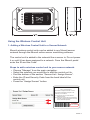
Monnit Wireless Control
User’s Guide
Inside the Box
You should find the following items in the box:
• Monnit™ Wireless Control Unit
• Antenna
Monnit Wireless Control Quick Start
• Create an iMonnit user account and assign a wireless gateway and sensors.
• Assign the wireless control device to the sensor network.
• Connect control relay’s to devices you wish to control.
• Plug the control device’s power supply into a power outlet.
• Pair the control relays with wireless sensor’s on the same sensor network.
• Set sensor conditions that will activate the relays.
IMPORTANT!
Disconnect all power to the control unit and the device to be controlled, before connecting
the control relay wires.
Monnit Wireless Control - Principle of Operation
The Monnit control unit has two separate relays that react in response to either the iMonnit.com web portal or a wireless sensor
on the network. The relays are capable of automatically controlling
motors, equipment or electrical devices. Monnit control is currently
available in 10-amp or 30-amp versions.
Four LED indicators let the user know if the device is powered
on, communicating with the online system and the status of each
relay.
Each of the units two relays can be automatically controlled
through the iMonnit software by pairing a relay directly with a sensor (which will use the sensor’s aware state to control the relay)
or by adding a control relay action in any notification setup in the
system. (See section 4.)
The user can also manually turn a relay on or off through the
iMonnit software. Manual changes can also be temporary based
on a set duration (ex. activate the relay for 10 minutes then return
to the default state). (See section 5.)
Example Use: If a water sensor detects water at a certain level in
a sump pit, the relay will switch ON, activating the pump. When
water is no longer detected, the relay will switch OFF, deactivating
the pump motor.
Monnit Wireless Control Features
• Allows for automated control.
• 10-amp or 30-amp units available.
• Two separate relays per unit.
• Can pair with two Monnit wireless sensors to activate upon
detection of set conditions.
• Can be triggered manually through online monitoring interface.
• AC powered, always on for immediate response from paired
sensors.
PAGE 2
Wireless Sensor
www.monnit.com
Relay 1
PN: MNA-X-CTL
© 2014 Monnit Corp.
Relay 2
Radio
Power
CONTROL
Using the Wireless Control Unit
1. Adding a Wireless Control Unit to a Sensor Network
Monnit wireless control units can be added to any Monnit sensor
network through the iMonnit online sensor monitoring software.
The control unit is added to the network like a sensor is. Do not power
it on until it has been assigned to a network. From the iMonnit portal
enter the ID and the Code.
Steps to add a wireless control unit to your sensor network.
•
•
•
•
Choose “Manage” from the main navigation.
Select the network you would like to add the control unit to.
Find the bottom of the section “Sensor List / Assign Sensor”.
Enter the ID and Security Code from the back label of the
control unit.
• Press the “Assign Sensor” button.
Contains FCC ID: ZTL-RFSC1
and IC: 9794A-RFSC1
This device complies with Part 15 of the
FCC Rules. Operation is subject to the
following two conditions:
(1) this device may not cause harmful
interference and
(2) this device must accept any interference
received, including interference that may
cause undesired operation.
ID: ######
Code: XXXXXX
PAGE 3
Once the control unit has been added to your network and before
connecting the relay wires to any equipment, power on the control
unit. Check that the bottom two LED indicators are illuminated green.
In the iMonnit online software, verify that data is being received by
viewing the history tab in iMonnit.
Each reading in the iMonnit software for the control device will show
the status of each of the two relays as either “On” or “Off”.
2. Wireless Control LED Indicators
Relay 1 and 2 - Solid green indicates that the relay is “on”.
No light indicates that the relay is “off”.
Radio Solid green indicates that the radio is active.
Flashing indicates radio communication with a
wireless sensor or gateway.
Power Solid green indicates that the device is powered.
3. Connecting the Relays
The relay acts as a switch on the line for your power source. The
relays are by default NORMALLY OPEN, so there is no connection
(lights for the relays will be off to indicate this). Return to the edit page
if you want the default state to be NORMALLY CLOSED.
The relay is just allowing the current to pass through, so it will be
installed inline on the power wire. It is not connected to power and
ground.
Monnit Control
Relay Wire
~
Power
PAGE 4
Device to
Control
4. Naming and Pairing Control Relays with Wireless Sensors
By clicking on the “Edit” tab, you can name each of the control relays
and set their default state.
Each of the units two relays can be paired with any Monnit wireless
sensor (currently over 40 types) to activate the relay when the sensor
detects user defined conditions (using the “Aware” state). To pair a
relay with a wireless sensor, enter the sensor’s ID from it’s bottom
label.
The control device will listen for messages from the iMonnit software, if
a sensor reading meets the “Aware” state conditions, the control relay
will automatically switch to the non-default state. When the sensor
reports a reading outside of the “Aware” state conditions, the relay will
switch back to it’s default state.
For an explanation on sensors and how the aware state is set, refer to
that sensor’s edit page in iMonnit.
The units two relays can also be controlled via sensor notification
settings. Create or edit an existing sensor notification and click on the
“Devices to Notify” tab. This will allow the notification to interact with
the control relays. Select a control relay from the list on the left and
click the arrow button to add it to the recipient list. Clicking the control
icon toggles their setting.
Note: Control devices have two relays per device that are controlled
separately. You can turn a relay on, off or toggle the state. You can
also set a duration by clicking on the timer icon. This will perform the
selected toggle (on/off/toggle) for a set duration, then change back.
PAGE 5
5. On Demand Relay Control
To test the functionality of the relays when connected to equipment, go
into the iMonnit portal, click on the control unit information bar from the
overview page, then click the “Control” tab:
Use the drop down to select what you want the relay to do (turn the
relay ON (close it), OFF (open it) or toggle the state). Once a selection
is made, another field will appear allowing you to set a duration of time
(in seconds) for the selected action to affect the relay, after which it will
switch back. If you want to simply switch the relay without a set time to
switch back, leave the field empty.
Once the Send Control command is sent, it will take the combined
time of the gateway heartbeat and the poll interval to affect the relay.
To speed up the process, force the gateway to communicate with the
server and/or lower the poll rate (in the Edit tab).
PAGE 6
Monnit Wireless Control Unit Specifications
Control Unit Relays
10-Amp Units
30-Amp Units
Initial Contact Resistance
Max. 100 mΩ
Max. 50 mΩ
Max Switching Power (resistive load)
2500VA 150W (NO)
1662VA 150W (NC)
8310VA
(30A 277VAC)
Max Switching Voltage
250 VAC,
100 VDC (0.5A)
277 VAC
Max Switching Current
10A (AC), 5A (DC)
30A
Nominal Operating Power
360 mW
Approx 800 mW
Operate Time (at nominal voltage / 20°C)
Max 10 ms
Max 20 ms
Release Time (at nominal voltage / 20°C)
Max 10 ms
Max 10 ms
Max Operating Speed
20 times/min
(at nominal switching
capacity)
20 times/min
(at nominal switching
capacity)
Number of Relays
2 (individually controlled)
Control Activation
- Automatic based on paired sensor
- Manual through iMonnit online software
Paired Sensor Relationship
1 sensor per relay (total: 2 sensors / device)
Power
Input Power
5.5 VDC @ 900 mA
Mechanical
Antenna
Connector: SMA
Gain (dBi): 5.0
Indicator Lights
Four LED indicators
- Power
- Radio (RF) communication
- Relay 1 status (On/Off)
- Relay 2 status (On/Off)
Enclosure
ABS Plastic
UL94V-0 flame rating
Dimensions
5.5 x 3.355 x 1.25 in.
(139.7 x 85.217 x 31.75 mm)
Weight
8 ounces
Environmental
Operating Temperature
Certifications:
-40° to +85° C (-40° to +185° F)
Industry
Canada
900 MHz product; FCC ID: ZTL- RFSC1 and
IC: 9794A-RFSC1.
868 and 433 MHz product tested and found
to comply with: CISPR 22:2008-09 / EN
55022:2010 - Class B and ETSI EN 300
220-2 V2.4.1 (2012-05).
PAGE 7
Warranty Information
(a) Monnit warrants that Monnit-branded products will be free from defects in materials and
workmanship for a period of one (1) year from the date of delivery with respect to hardware
and will materially conform to their published specifications for a period of one (1) year
with respect to software. Monnit may resell sensors manufactured by other entities and are
subject to their individual warranties; Monnit will not enhance or extend those warranties.
Monnit does not warrant that the software or any portion thereof is error free. Monnit will
have no warranty obligation with respect to Products subjected to abuse, misuse, negligence or accident. If any software or firmware incorporated in any Product fails to conform
to the warranty set forth in this Section, Monnit shall provide a bug fix or software patch
correcting such non-conformance within a reasonable period after Monnit receives from
Customer (i) notice of such non-conformance, and (ii) sufficient information regarding such
non-conformance so as to permit Monnit to create such bug fix or software patch. If any
hardware component of any Product fails to conform to the warranty in this Section, Monnit
shall, at its option, refund the purchase price less any discounts, or repair or replace nonconforming Products with conforming Products or Products having substantially identical
form, fit, and function and deliver the repaired or replacement Product to a carrier for land
shipment to customer within a reasonable period after Monnit receives from Customer (i)
notice of such non-conformance, and (ii) the non-conforming Product provided; however,
if, in its opinion, Monnit cannot repair or replace on commercially reasonable terms it may
choose to refund the purchase price. Repair parts and replacement products may be
reconditioned or new. All replacement products and parts become the property of Monnit.
Repaired or replacement products shall be subject to the warranty, if any remains, originally
applicable to the product repaired or replaced. Customer must obtain from Monnit a Return
Material Authorization Number (RMA) prior to returning any Products to Monnit. Products
returned under this Warranty must be unmodified.
Customer may return all Products for repair or replacement due to defects in original materials and workmanship if Monnit is notified within ninety (90) days of customer’s receipt of
the product. Monnit reserves the right to repair or replace products at its own and complete
discretion. Customer must obtain from Monnit a Return Material Authorization Number
(RMA) prior to returning any products to Monnit. Products returned under this Warranty
must be unmodified and in original packaging. Monnit reserves the right to refuse warranty
repairs or replacements for any products that are damaged or not in original form. For
products outside the ninety-day warranty period repair services are available at Monnit at
standard labor rates for a period of one year from the Customer’s original date of receipt.
(b) As a condition to Monnit’s obligations under the immediately preceding paragraphs,
Customer shall return Products to be examined and replaced to Monnit’s facilities, in
shipping cartons which clearly display a valid RMA number provided by Monnit. Customer
acknowledges that replacement products may be repaired, refurbished or tested and found
to be complying. Customer shall bear the risk of loss for such return shipment and shall
bear all shipping costs. Monnit shall deliver replacements for Products determined by Monnit to be properly returned, shall bear the risk of loss and such costs of shipment of repaired
products or replacements, and shall credit Customer’s reasonable costs of shipping such
returned Products against future purchases.
(c) Monnit’s sole obligation under the warranty described or set forth here shall be to repair
or replace non-conforming products as set forth in the immediately preceding paragraph, or
to refund the documented purchase price for non-conforming Products to Customer. Monnit’s warranty obligations shall run solely to Customer, and Monnit shall have no obligation
to customers of Customer or other users of the Products.
PAGE 8
Limitation of Warranty and Remedies.
THE WARRANTY SET FORTH HEREIN IS THE ONLY WARRANTY APPLICABLE TO
PRODUCTS PURCHASED BY CUSTOMER. ALL OTHER WARRANTIES, EXPRESS
OR IMPLIED, INCLUDING BUT NOT LIMITED TO THE IMPLIED WARRANTIES OF
MERCHANTABILITY AND FITNESS FOR A PARTICULAR PURPOSE ARE EXPRESSLY
DISCLAIMED. MONNIT’S LIABILITY WHETHER IN CONTRACT, IN TORT, UNDER ANY
WARRANTY, IN NEGLIGENCE OR OTHERWISE SHALL NOT EXCEED THE PURCHASE
PRICE PAID BY CUSTOMER FOR THE PRODUCT. UNDER NO CIRCUMSTANCES
SHALL MONNIT BE LIABLE FOR SPECIAL, INDIRECT OR CONSEQUENTIAL DAMAGES. THE PRICE STATED FOR THE PRODUCTS IS A CONSIDERATION IN LIMITING
MONNIT’S LIABILITY. NO ACTION, REGARDLESS OF FORM, ARISING OUT OF THIS
AGREEMENT MAY BE BROUGHT BY CUSTOMER MORE THAN ONE YEAR AFTER
THE CAUSE OF ACTION HAS ACCRUED.
IN ADDITION TO THE WARRANTIES DISCLAIMED ABOVE, MONNIT SPECIFICALLY
DISCLAIMS ANY AND ALL LIABILITY AND WARRANTIES, IMPLIED OR EXPRESSED,
FOR USES REQUIRING FAIL-SAFE PERFORMANCE IN WHICH FAILURE OF A PRODUCT COULD LEAD TO DEATH, SERIOUS PERSONAL INJURY, OR SEVERE PHYSICAL
OR ENVIRONMENTAL DAMAGE SUCH AS, BUT NOT LIMITED TO, LIFE SUPPORT OR
MEDICAL DEVICES OR NUCLEAR APPLICATIONS. PRODUCTS ARE NOT DESIGNED
FOR AND SHOULD NOT BE USED IN ANY OF THESE APPLICATIONS.
PAGE 9
Certifications
United States FCC
This equipment has been tested and found to comply with the limits for a Class B digital
devices, pursuant to Part 15 of the FCC Rules. These limits are designed to provide
reasonable protection against harmful interference in a residential installation. This
equipment generates, uses, and can radiate radio frequency energy and, if not installed
and used in accordance with the instruction manual, may cause harmful interference to
radio communications. However, there is no guarantee that interference will not occur in
a particular installation. If this equipment does cause harmful interference to radio or
television reception, which can be determined by turning the equipment off and on, the
user is encouraged to try to correct the interference by one of more of the following
measures:
• Reorient or relocate the receiving antenna
• Increase the separation between the equipment and receiver
• Connect the equipment into an outlet on a circuit different from that to which
the receiver is connected.
• Consult the dealer or an experienced radio/TV technician for help.
Warning: Changes or modifications not expressly approved by Monnit could void
the user’s authority to operate the equipment.
RF Exposure
WARNING: To satisfy FCC RF exposure requirements for mobile
transmitting devices, the antenna used for this transmitter must not be
co-located in conjunction with any other antenna or transmitter.
Monnit Wireless Control Contains:
FCC ID: ZTL-RFSC1
This device has been designed to operate with an approved antenna listed below, and
having a maximum gain of 5.1 dBi. Antennas not included in this list or having a gain
greater than 5.1 dBi are strictly prohibited for use with this device. The required antenna
impedance is 50 ohms.
To reduce potential radio interference to other users, the antenna type and its gain should
be so chosen that the equivalent isotropically radiated power (EIRP) is not more than that
required for successful communication.
Approved Antennas
The following antennas are approved for use with Monnit devices.
• Hyperlink HG905RD-RSP (5.1 dBi Rubber Duck)
• Pulse W1063 (3.0 dBi Rubber Duck)
• ChangHong GSM-09 (2.0 dBi Rubber Duck)
• Specialized Manufacturing MC-ANT-20/4.0C (4” whip)
PAGE 10
Canada (IC)
English
Under Industry Canada regulations, this radio transmitter may only operate using an
antenna of a type and maximum (or lesser) gain approved for the transmitter by Industry
Canada. To reduce potential radio interference to other users, the antenna type and its gain
should be so chosen that the equivalent isotropically radiated power (e.i.r.p.) is not more
than that necessary for successful communication.
The radio transmitter (IC: 9794A-RFSC1) has been approved by Industry Canada to operate with the antenna types listed on previous page with the maximum permissible gain and
required antenna impedance for each antenna type indicated. Antenna types not included
in this list, having a gain greater than the maximum gain indicated for that type, are strictly
prohibited for use with this device.
This device complies with Industry Canada licence-exempt RSS standard(s). Operation is
subject to the following two conditions: (1) this device may not cause interference, and (2)
this device must accept any interference, including interference that may cause undesired
operation of the device.
French
Conformément à la réglementation d’Industrie Canada, le présent émetteur radio peut
fonctionner avec une antenne d’un type et d’un gain maximal (ou inférieur) approuvé pour
l’émetteur par Industrie Canada. Dans le but de réduire les risques de brouillage radioélectrique à l’intention des autres utilisateurs, il faut choisir le type d’antenne et son gain de
sorte que la puissance isotrope rayonnée équivalente (p.i.r.e.) ne dépasse pas l’intensité
nécessaire à l’établissement d’une communication satisfaisante.
Le présent émetteur radio (IC: 9794A-RFSC1) a été approuvé par Industrie Canada pour
fonctionner avec les types d’antenne figurant sur la page précédente et ayant un gain admissible maximal et l’impédance requise pour chaque type d’antenne. Les types d’antenne
non inclus dans cette liste, ou dont le gain est supérieur au gain maximal indiqué, sont
strictement interdits pour l’exploitation de l’émetteur.
Le présent appareil est conforme aux CNR d’Industrie Canada applicables aux appareils
radio exempts de licence. L’exploitation est autorisée aux deux conditions suivantes : (1)
l’appareil ne doit pas produire de brouillage, et (2) l’utilisateur de l’appareil doit accepter
tout brouillage radioélectrique subi, méme si le brouillage est susceptible d’en compromettre le fonctionnement.
PAGE 11
Error Reporting, Troubleshooting and Support
For technical support and troubleshooting tips please visit our support library online at
http://www.monnit.com/support/. If you are unable to solve your issue using our online
support, email Monnit support at [email protected] with your contact information and a
description of the problem, and a support representative will call you within one business
day. For error reporting, please email a full description of the error to [email protected].
Additional Information and Support
For additional information or more detailed instructions on how to use your Monnit Wireless
Sensors or the iMonnit Online System, please visit us on the web at
http://www.monnit.com/support/.
For additional information or more detailed instructions
on how to use your Monnit Wireless Sensors or sensor
monitoring software, please visit us on the web at
http://www.monnit.com/support/.
Monnit Corporation
7304 South Cottonwood
Suite #204
Midvale, Utah 84047
801-561-5555
www.monnit.com
All trademarks are property of Monnit. © 2009-2014 Monnit Corp. All Rights Reserved.
M-UG12-1A (07/14)