1
EFN324 User Guide
EDA 1200
Copyright
Copyright Ericsson AB 20082009. All rights reserved.
Disclaimer
No part of this document may be reproduced in any form without the written permission of the copyright owner. The contents of this document are subject to revision without notice due to continued progress in methodology, design and manufacturing. Ericsson shall have no liability for any error or damage of any kind resulting from the use of this document.
Trademark List
Windows®
Windows is a registered trademark of Microsoft Corporation.
Apache™
Apache is a trademark of The Apache Software Foundation.
Extreme Networks®
Extreme Networks is a registered trademark of Extreme Networks, Inc.
Linux®
Linux is a registered trademark of Linus Torvalds.
Wind River®
Wind River is a registered trademark of Wind River Systems, Inc.
vMAN™
vMAN is a trademark of Extreme Networks, Inc.
All trademarks are properties of their respective owners.
Legal Notice
The EFN324 software is built using Open Source Licensed software. Refer to the Third Party License Agreements document for copies of the licenses.
Contents
1
1 Introduction.................................................................................................1
2 Introduction to the EFN324.........................................................................5
3 Front Panel Description..............................................................................6
4 Basic Concepts...........................................................................................8
5 Switching Functions.................................................................................27
6 Topologies.................................................................................................48
7 Configuring Connections.........................................................................54
8 Security Functions....................................................................................60
9 Network Functions....................................................................................72
10 System Functions....................................................................................77
11 Maintenance.............................................................................................81
12 EFN324 Alarms........................................................................................84
13 Command Line Interface.........................................................................93
14 Software Components under Open Source Licences.........................166
Error! No text of specified style in document.
Glossary 168
Index
170
Glossary
1
Introduction
This guide describes how to use the EFN324. It describes its functions, Command Line Interface (CLI) and use in EDA. This guide is intended for operation and maintenance personnel.
Some of the EFN324 functions are described in the EDA 1200 System Description. Reading the System Description before reading this guide is recommended.
Important!
When used with PEM or ServiceOn PEM, most of the EFN324 functions (including VLANs) are configured automatically by the management system. Any duplicate configurations created using the Command Line Interface (CLI) commands described in this manual will be overwritten by the management system.
Throughout this guide, the EFN324 is also referred to as the EFN and an Ethernet access switch. These terms are interchangeable.
The guide can be printed on a monochrome printer, but the pictures and illustrations may be more difficult to understand. 1.1
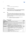
Revision History
This guide is valid for the EFN324 software released in EDA 4.3. This guide is also valid for ELN220 running the same software. Other product version with functions not described in this guide may be available.
1.1.1
This Version (S)
Other than editorial changes, this document has been revised as follows:
1.1.2
Flows section (section 4.11 on page 22) updated with better explanations.
A note added in Table 16 for the statistics command.
Version N
Other than editorial changes, this document has been revised as follows:
IndexIndex
1.1.3
Section 13.8.20 (SNMP) has been updated with SNMPv3 support.
Section 13.8.17, Section 13.9.10 and section 13.9.2 have been updated with SFTP and FTPS support.
Section 13.8.12 has been updated with dynamic VLAN management support.
Version M
Other than editorial changes, this document has been revised as follows:
1.1.4
Reference in section 4.10.1 on page 21 corrected
Version L
Other than editorial changes, this document has been revised as follows:
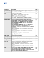
1.1.5
Section 4.8 on page 13 (Virtual LAN and VLAN tag) has been updated
The illustrations and descriptions in section 5.5 on page 39 updated to make them easier to understand
Connection Bandwidth limitation description added in section 4.10.1 on page 21
Connect VLAN command corrected (second_ethertype, second_tags) in section 13.8.6 on page 114
Version K
Other than editorial changes, this document has been revised as follows:
1.1.6
The maximum number of daisy chained standalone EFN324 has been corrected to two (2) in section 9.1 on page 72 and Figure 29 on page 73.
Revision J
The guide is based on the EFN324 User Guide 1553CXP 901 0022 Uen H. Other than editorial changes, this document has been revised as follows:
Changes made to the document structure.
Glossary
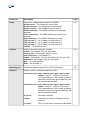
1.2
EFN324 as an embedded flexible block added. A number of changes flowed from this, including the following:
Additional CLI commands, and extensions to existing CLI commands.
A virtual MAC description for an embedded node.
Additional topology description.
Replacement of an EFN324 added in section 11.2 on page 82.
Quality of Service for EFN324 added.
Further DHCP Option 82 options added.
PPPoE added.
Configurable first Ethertype added.
The default snmp write_community has been changed, from private to public. See section 13.8.20 on page 137.
Descriptions of the debugging commands, including packet_logger and trace_logger commands included, see section 13.10 on page 158.
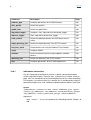
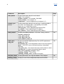
Conventions
The following conventions apply to textual instructions (not screen shots):
ToolsOptions means: Choose the Tools menu item, then choose the Options menu item.
Bold Courier letters mark field titles in a Graphical User Interface (GUI), or text typed by the user (input) in files or the Command Line Interface (CLI, such as Command prompt).
Regular Courier letters mark text output in a CLI.
OK : A button in a GUI.
<Server> is a parameter that should be replaced with the actual value. <> symbols are not typed.
[argument] the brackets indicate that this argument is optional and can be omitted. If the argument is used, the brackets must not be typed.
IndexIndex
{argument1|argument2} the brackets and pipe indicate that either argument1 or argument 2 can be used as a value for this parameter.
Press CTRL+X means hold down the Ctrl key and press the x key.
Glossary
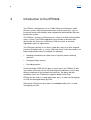
2
Introduction to the EFN324
The EFN324 is designed for use in a Public Ethernet environment. Public Ethernet systems require enhanced functions and characteristics, such as increased security and reliability, when compared to with traditional Ethernet based LAN systems. The EFN324 is used as an Ethernet access switch in an Ethernet based fiber access system. The EFN324 aggregates physical fiber or electrical links directly from the Endusers. It then relays Enduser traffic to and from aggregation nodes on higher levels. The EFN works primarily as an Access Node but it may also, when required, interact with higher levels as a Layer 2 Ethernet switch. Such interventions are broad ranging and include, for example, the following:
Snooping information from higher level as input for packet switching decisions.
Changing header contents.
Discarding packets.
VLAN technology (IEEE 802.1Q) plays a central role in the EFN324. VLANs are used for enhanced security and for distinguishing different services with different requirements for transport characteristics, like delay and jitter, availability and so on. EFN324 also supports double VLAN Tags.
EFN324 can be used as a standalone node, that is, a node not managed by an ECN, but managed directly by PEM.
Alternatively, EFN324 can be used as an embedded node, that is, a node managed by an ECN.
IndexIndex
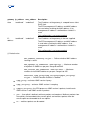
3
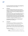
Front Panel Description
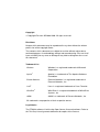
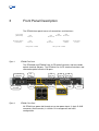
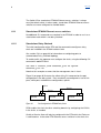
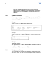
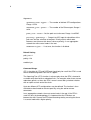
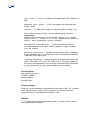
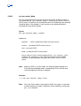
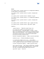
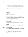
The EFN324 front panel houses all connections and interfaces.
Cons ole
(RS232)
Power input
A and B
FE
Port 1
FE
Port 23
FE
Port 2
FE
Port 24
FE ports LEDs
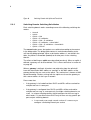
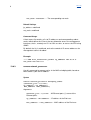
Figure 1
Gb
Port 25
Gb
Port 26
Sys tem
LEDs
Fan tray
cover
Gb ports LEDs
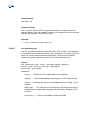
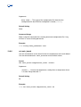
EFN324f Front Panel
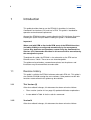
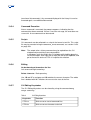
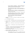
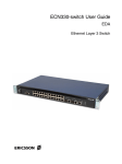
The EFN324df and EFN324f have 24 FE optical interfaces and two combo opticalelectrical Gb ports. The EFN324c has 24 FE electrical interfaces and two combo opticalelectrical Gb ports. Console (RS232)
Power input A and B
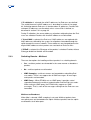
Figure 2
FE
Port 1
FE
Port 2
FE
Port 23
9
11
10
12
FE
Port 24
Gb
Port 25
Gb
Port 26
System LEDs
Fan tray cover
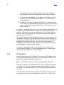
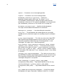
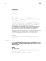
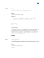
EFN324c Front Panel
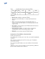
All EFN324 are power fed through one or two power inputs. A 9 pin DSUB connector (Serial console) is used for CLI management and initial configuration. Glossary
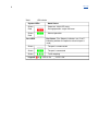
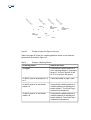
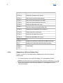
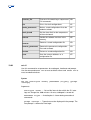
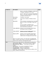
Table 1
LED Indication
System LEDs Green
Red
______
Green
Red
█████
______
█████
Port LEDs
Node Status
Poweron: Initial LED state During operation: major HW error
Normal operation
Port Status (The Gb ports indicators are O or E, indicating whether the optical or electrical port is used)
Green
______
The port is unconnected
Green
█████
The port is connected
Green
█_█_█_
Traffic ongoing
Legend: █ or █ : LED is On _ : LED is Off
IndexIndex
4
Basic Concepts
The concepts described in this chapter are the startingpoint for what an operator sees, and needs to understand. 4.1
Physical View
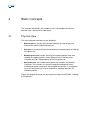
The most important concepts are the following:
Ethernet port is the physical interface between an external physical Ethernet link and the network processor.
Host port is the physical interface between the network processor and the host processor.
Network processor handles receiving of incoming packets from and sending of outgoing packets to the Ethernet links. It handles most switching decisions independently of the host processor.
Host processor (also called control processor) controls the Network Processor. This includes assistance in program loading and restart, executing of control commands and reception of counters. In exceptional cases the host processor may be involved in switching decisions for individual packets.
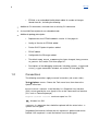
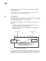
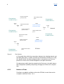
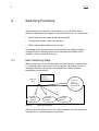
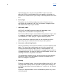
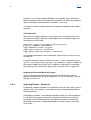
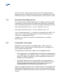
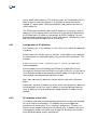
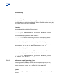
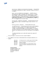
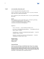
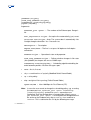
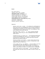
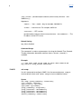
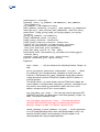
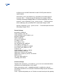
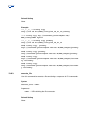
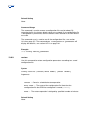
Figure 3 on page 9 illustrates the basic physical view of the EFN234, showing the listed items.
Glossary
. . .
Ethernet
links
Ethernet
Ports
EFN324 Memory commonly shared between host and network processors
Network processor
switch
Host Port
Host processor
Local
COM port
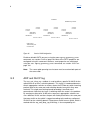
Figure 3 Basic Physical View of the EFN324
The network and host processors communicate physically through shared memory. The communication may logically be divided into the following two groups:
Management traffic to an external management site. This is traffic over IP. In order for this traffic to flow, a connection through the switch between an Ethernet port and the host port must be configured. The operator must also configure an IP address for the host processor.
All other communication. From an operator’s point of view this traffic takes place ‘under the surface’, since no special configuration or other involvement from the operator is required for it to happen. Examples of this type of traffic are control messages from host processor to network processor, and packets forwarded from the network processor to the host processor during the switching procedure, for example, IGMP messages. It is also possible for an operator to directly communicate with the Ethernet access switch from a terminal through a local COM port. 4.2
Management Interface
An operator communicates with the system through a management interface. EFN324 offers both a CLI and a MIB interface. The latter may be used by management systems like PEM. The MIB interface may also be used for machinemachine communication with overlying management systems. IndexIndex
4.3
Standalone and Embedded Nodes
A standalone node in EDA 1200 is managed directly by PEM. It is transparent to any ECN that may be present in the network.
An embedded node is managed by an ECN using SNMP. The EFN324 is configured as a flexible block, with a Switch ID.
4.4
Ethernet Access Switch IP Address
The EFN324 IP address can be determined in either of the following ways:
4.4.1
configured as a static IP address, for standalone Ethernet access switches, see section 4.4.1 on page 10.
fetched from the ECN using DHCP, for embedded Ethernet access switches, see section 4.4.2 on page 10.
Static IP Address
If the EFN324 is a standalone node, its IP address is defined during initial configuration. The initial configuration (using CLI commands) also defines the network mask and default gateway IP address. See the EFN324 Installation Guide for the commands used during initial configuration.
4.4.2
DHCP IP Address
If the EFN324 is an embedded node, it fetches its IP address from the ECN using DHCP when it starts up after its initial configuration.
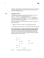
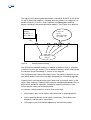
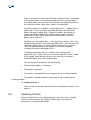
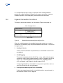
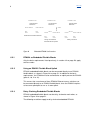
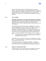
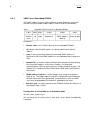
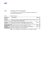
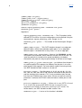
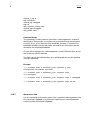
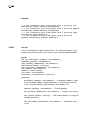
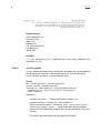
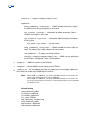
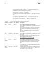
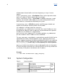
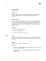
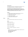
When the IP address is requested, the Ethernet access switch uses the Management VLAN configured during installation. If a reply is not received, four retries, using exponential timeout values, are sent. The process is illustrated in Figure 4 on page 11. There is no support for using an unmanaged VLAN.
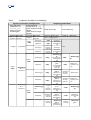
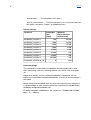
DHCP options 43, 60 and 161 are used. Option 43 contains “<IP address of TFTP server storing the configuration file>;<Configuration filename>;<IP address of trap receiver>”. See Table 2 on page 11 for details of the strings used for options 60 and 161. Glossary
Table 2
DHCP Values for Options 60 and 161
Option 60
Option 161
Value
Ethernet access switch’s hardware ID and Switch ID
Ethernet access switch’s software version number
Examples
“KDU137389/1,R1A;SID=42”
“CXP 901 0022 R8B01”
Retrieve Management VLAN ID from flash
Send tagged DHCP request Timeout
No
DHCP Response received?
Yes
Yes
DHCP Response No
Valid?
Use IP Address from DHCP
Figure 4
4.5
DHCP Procedure
Resource
All the functions of the system are expressed, or modeled, in the CLI as Resources. The MIB interface uses a similar model. The Resource concept resembles objects in objectoriented programming. Instead of ‘resource’, words like ‘resource object’, ‘resource instance’ or ‘object’ could be used. A Resource can also be referred to by only its name. For example, instead of using ‘the autologout parameter in the CLI resource’, refer to ‘autologout in CLI’. Examples of resource objects in the EFN324 CLI include main_board, ethernet_port and host_port. ethernet_port is an example of an indexed resource type, in that there are multiple instances, separated using an index:
ethernet_port 1
IndexIndex
ethernet_port 2
ethernet_port 3
…
ethernet_port 25
ethernet_port 26
4.6
Attribute
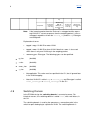
Each resource object contains data in the form of attributes. There are three types of attributes:
Configuration attributes. These are also called parameters or configuration parameters. Their values are determined and set by an operator.
Status attributes. Their values are determined and set by the system itself.
Info attributes. Info parameters are set at the factory, during production, and are not supposed to be changed during the system lifetime.
The values of all types of parameters may be read using ‘get’ commands.
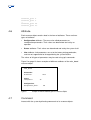
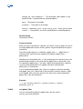
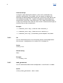
Figure 5 on page 12 shows examples of different attributes of the main_board resource object.
main_board
Information:
# serial no = 1234
Status:
# temperature = 56
Configuration:
# temperature_limit = 80
Figure 5 4.7
Example of Different Attribute Types of a Resource Object
Command
Interact with the system by directing commands to its resource objects. Glossary
Parameter values (configuration attributes) may be read from the system using get commands.
The configuration attributes values are set, modified or deleted using set, add, remove, connect, disconnect and other commands. There are also some system commands that do not relate to objects. For example, exit.
4.8
Virtual LAN and VLAN tag
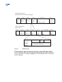
Virtual LAN (VLAN) is a technique used to logically separate several independent networks that share a common physical infrastructure.
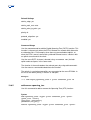
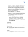
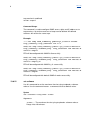
The IEEE 802.1Q standard describes how a 4byte tag is inserted into Ethernet packets, between the source address and the length or type field, to specify the VLAN for the packet. The 4 byte tag consists of the following:
A 2-byte Tag Protocol Identifier
A 2-byte Tag Control Information
The Tag Control Information consists of a 12bit VLAN ID, a 3bit priority field and a 1bit Canonical Format Indicator. The latter is only used for Token Ring transmissions. IndexIndex
Original (”DIX type II”) Ethernet frame; also called “untagged”:
8 bytes 6 bytes 6 bytes 2 bytes 46 – 1500 bytes 4 bytes
Pre
Dest.
Source
Type/
Data (0 – 1500 bytes)
Frame
am
address
address
length
and
check
field
Pad (46 – 0 bytes)
sequence
ble
802.1Q VLAN tagged Ethernet frame:
8 bytes 6 bytes 6 bytes 4 bytes 2 bytes 46 – 1500 bytes 4 bytes
Pre
Dest.
Source
802.1Q
Type/
Data
Frame
am
address
address
VLAN
length
and
check
Tag
field
Pad
sequence
ble
Tag
Protocol
Identifier User priority
CFI
VLAN ID
3 bits 1 bit 12 bits
Tag Control Information
(0x8100)
2 bytes 2 bytes
Figure 6
IEEE 802.1Q tag
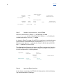
EFN324 supports zero, one and two VLAN tags as described above. Within the CLI and in the MIB, the terms ‘tag’ and ‘second_tag’ are used for historical reasons, but there is no direct mapping to the more common terms “Outer and Inner VLAN tag”.
Glossary
Single tag frame
Ethernet
Header
CLI notation:
VLAN
Frame check
sequence (FCS)
Data
tag
Double tag frame
Ethernet
Header
CLI notation:
Figure 7
Outer
VLAN
second_tag
Inner
VLAN
Data
Frame check
sequence (FCS)
tag
Definition of tag and second_tag for EFN324
In the CLI, the VLAN ID is called tag, the ethertype is called first_ethertype and the 3 bit priority field is called p_tag. Similarly, for second tag the prefix <second_> is added.
As shown in Figure 7 on page 15, the EFN is inconsistent in relating the terms Outer and Inner VLAN and the terms used in the CLI (tag, second_tag). When one tag is present, tag denotes the Outer VLAN, but with two VLAN tags, tag denotes the Inner VLAN.
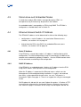
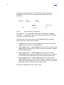
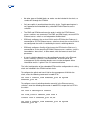
The following figure illustrates the Ingress and Egress connections. Note that to enable traffic in both directions, both the ingress and egress connections must be configured for a switching domain. Ingress
connection
Upstream
Egress
connection
Switching
Domain
Service VLAN
EFN324
Downstream
Figure 8
Egress
connection
Ingress
connection
Ingress and Egress Connections
On the ingress connection, the EFN324 will allow packets with the following Tag Protocol Identifiers (Ethertype): IndexIndex
QVLAN (0x8100)
SVLAN (0x88a8)
Extreme Networks vMAN (0x9100)
SVLAN (0x9200)
The values for these Tag Protocol Identifiers cannot be configured at the ingress connection.
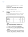
Only one of the Tag Protocol types may be used within the same service. The VLAN ID (and optionally, the upstream destination IP address) of the incoming frames defines the switching domain that the frame is forwarded to. If the incoming frame has either an Ethertype that is not allowed or VLAN ID that is not defined, the frame is discarded. If the frame is not discarded, VLAN mapping and tagging takes place. Table 3 on page 16 lists the possible ways to define the ingress configuration. The outer VLAN ID is the only mandatory parameter.
Table 3
Ingress Connection Definitions
Outer VLAN ID
(tags for single
tagged frames second_tags for doubletagged frames)
Inner VLAN ID
(tags for doubletagged frames)
Destination IP address
Single VLAN tag frame
None
Specific address
IP network
Double VLAN tag frame
Specific value
Specific value Wild card (using *)
Specific address
IP network
Specific value
Range
All (using *)
Untagged
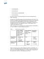
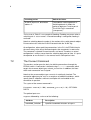
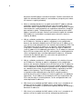
Table 4 on page 18 lists the VLAN mapping possibilities in the EFN324. The table lists the configurable parameters for the egress connection and what are the results of each specific configuration. It is also possible to configure the p
bit in exactly the same way as the Ethertype, just using a Glossary
pbit value instead of Ethertype. The way that the ingress connection is configured must be taken into consideration when settings the egress connection. Upstream
Ingress
connection
Egress
connection
Switching
Domain
tags
Figure 9
EFN324
Service VLAN
tag
Ingress and Egress tag Configuration
For example if tags in the ingress connection is configured as untagged, setting the tag in the egress connection to transparent will have no meaning since there is no VLAN ID to copy.
The table shows four main scenarios that are depended on the incoming format of the frame and the desired output:
1
Untagged traffic: use this to send untagged traffic from the EFN, with no regards to the format of the incoming packets.
2
Single tagged frame in Single tagged frame out: use this to send a single tagged frame out where the sent VLAN can either be translated or copied from the incoming frame.
3
Single tagged frame in – Double tagged frame out: Use this to send double tagged frames out with a fixed outer VLAN and an Inner VLAN that is either translated or copied from the VLAN tag of the incoming traffic. 4
Double tagged frame in – Double tagged frame out: Use this to send double tagged frames out with an outer VLAN that is copied from the outer VLAN of the incoming frame and an Inner VLAN that is either translated or copied from the inner VLAN tag of the incoming traffic. See also the explanation of terms after the table.
IndexIndex
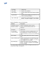
Table 4
Configuration Possibilities for VLAN Mapping
Egress Connection Configuration
Type and Value
configuration for
second_tag
(Outer VLAN for
doubletagged)
VLAN ID Ethertype
Not
Not
applicable applicable
Type and Value
configuration for tag
(Inner VLAN for doubletagged,
Outer VLAN for singletagged )
VLAN ID Ethertype
untagged
tagged
<Idx>
Untagged
Not applicable
Not
applicable
Outgoing packet Sent
Outer VLAN Tag
Inner VLAN Tag
VLAN ID
VLAN ID
<Idx>
transparent
<Idx>
transparent
transparent
Ethertype
None – untagged packet
<Ethertype>
<Ethertype>
Ethertype
VLAN ID of
incoming
outer tag
VLAN ID of
incoming
outer tag
<Ethertype>
Ethertype of
incoming outer
tag
<Ethertype>
None
Ethertype of
incoming outer
tag
<Ethertyp
<Ethertype>
<Idy>
tagged
<Idx>
transparent
tagged
<Idy>
<Idy>
<Ethertyp
e> or
transparent
pe>
<Ethertyp
e>
<Idx>
Ethertype of
incoming outer
tag
pe> or
Ethertype of
incoming outer
tag
<Etherty
VLAN ID of
incoming
outer tag
<Ethertype>
pe> or
Ethertype of
incoming outer
tag
VLAN ID of
incoming
outer tag
Ethertype of
incoming outer
tag
or Ethertype
of incoming
outer tag
<Etherty
<Ethertype>
<Idy>
transparent
<Idy>
transparent
transparent
e>
or Ethertype of <Idx>
incoming outer
tag
<Etherty
<Ethertyp
e> or
<Ethertyp
transparent
e>
tagged
<Idx>
<Ethertyp
e> or
Ethertype of
incoming outer
tag
<Idx>
<Ethertyp
e>
<Etherty
transparent
transparent
VLAN ID
of
incoming
outer tag
<Ethertype>
VLAN ID of
incoming
outer tag
VLAN ID of
incoming
outer tag
pe> or
Ethertype of
incoming outer
tag
<Etherty
pe> or
Ethertype of
incoming outer
<Idx>
VLAN ID of
incoming
inner tag
Ethertype of
incoming inner
tag
<Etherty
pe>
Glossary
tag
<Etherty
transparent
Note:
VLAN ID of
incoming
outer tag
pe> or
Ethertype of
incoming outer
tag
VLAN ID of
incoming
inner tag
Ethertype of
incoming inner
tag
If the incoming packet from the Enduser is untagged and the egress tag VLAN ID is set to transparent, then the outgoing packet is sent as untagged, regardless of how the second_tag and the tag Ethertype are configured.
Explanation of terms:
4.9
tagged <Idy>: VLAN ID for outer VLAN.
tagged <Idx>: VLAN ID for inner VLAN. Note that <Idx> is also used when there is only one VLAN tag in the outgoing packet.
<Ethertype>: Ethertype. The following types can be specified:
q_vlan (0x8100)
svlan (0x88A8)
vman_vlan
(0x9100)
s_vlan (0x9200)
Not applicable: This value must be specified in the CLI, but is ignored later in the VLAN mapping.
Note that VLAN ID is called tag or second_tag and Ethertype is called first_ethertype or second_ethertype in the CLI.
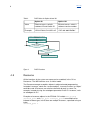
Switching Domain
In the EFN324 design the switching domain is a central resource. For historical reasons, the switching domain is called ‘vlan’, with small letters, in the CLI. The switching domain is used by the operator as a connection point in the switch for ports belonging to a particular VLAN. The switching domain is IndexIndex
capable of performing much more sophisticated switching than an ordinary learningbridge switch. In the descriptions in this guide, ‘switching domain’ is used, for the sake of clarity, instead of the ‘vlan’ notation used in the CLI. 4.10
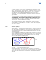
Connections
Ports, switching domains and connections are central concepts for switching in the EFN324. A port is either an Ethernet port (called ethernet_port in the CLI) or the Host port (called host_port in the CLI). For a packet to travel through the switch, the following two connections must be defined:
The ingress connection: the connection between the ingress port on which the packet arrived and a switching domain.
The egress connection: the connection between the switching domain and an egress port.
Incoming packet
Ethernet
port x
Outgoing packet
Ethernet
port y
EFN324
Egress connection
Ingress connection
Switching domain
Figure 10 Ingress and Egress Connections
Even though the 26 Ethernet ports and 200 switching domain resources are, by default, present from the start, connections must be defined (configured) by the operator. A connection is created or deleted using the connect or disconnect Glossary
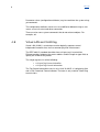
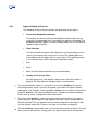
commands. Note that apart from the management VLAN, which is configured during initial configuration, the connections are made automatically by the Public Ethernet Manager (PEM). 4.10.1
Bandwidth Limitation
A bandwidth limitation may be imposed on each connection (ingress and egress). It is implemented as a bandwidth profile (se set bandwidth_limitation in section 13.8.8 on page 118), which is then selected for a specific connection with the connect vlan command (see section 13.8.6 on page 114. Up to 32 profiles can be used. Eight profiles are created per default and can be modified. When a bandwidth limitation profile is applied to a connection it will limit the following traffic types:
Applied on an Ingress connection: unicast and broadcast packets
Applied on an Egress connection: unicast Multicast and broadcast packets
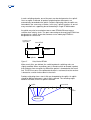
Unless VLAN per Enduser is used, only the connections from the switching domain to the downlink port should be configured with bandwidth limitation. That is egress connection for the downstream and ingress for the upstream. The reason is that these are the only connections that are connected to a single Enduser. The connection from the switching domain will transport traffic from several Endusers and there is therefore no meaning in applying bandwidth limitation to that connection.
Ingress
Egress
BW
BW
BW
BW
Ingress
Egress
Ingress
Egress
Switching
domain
Ingress
BW
BW
Egress
Figure 11
EFN324
Bandwidth Limitation for Multiuser Service VLAN
Uplink
IndexIndex
4.11
Flows
Flows are used to distinguish the different levels of Quality of Service (QoS) within a connection (see section 4.10 on page 20). A group of packets within a connection can be given preferential treatment by classifying them into a flow. Each flow is identified by either the pbits or the DSCP values in the packet. The flow determines the priority and reliability for the packets, along with the bandwidth limitation or the policing to be applied on the flow. The priority designates an output queue. The reliability indicates whether the packet should be discarded if the EFN324 has insufficient empty buffers. The higher the priority, the faster the packets are sent out. The higher the reliability, the lower the probability of the packets getting discarded in overflow situations.
Flows within a connection to an uplink port handles traffic from all Endusers using the VLAN flow (see Figure 12 on page 23). This must be taken in consideration when the connections and flows from the switching domain to the uplink port are configured.
4.11.1
Flows in Connections The EFN does not differentiate between uplink and downlink packet processing. The flows must be configured correctly, accordingly to their direction. Glossary
Ingress Connection
Connections
VLAN1Port x
VLAN
1+2
Port
x
output stream toward
port Z
(upstream traffic)
Switching
Domain
VLAN 1
Flow1
output stream toward
Ingress Connection
port X
(Downstream traffic)
Port
z
Ingress Connection
(upstream traffic)
Connections
VLAN2Port x
Ingress Connection
Switching
Domain
VLAN 2
Flow1
Connections
VLAN2Port Y
Figure 12
Network
Connections
VLAN2Port z
(upstream traffic)
Port
Y
VLAN
1+2
output stream toward
port Z
Flow1
output stream toward
the port X
VLAN
2
Connections
VLAN1Port z
Flow1
Flow1
Flow2
Ingress Connection
(Downstream traffic)
Flow2
output stream toward
port Y
EFN324
Flow Directions
As illustrated, flows within the connections between the switching domain and the uplink port (Port z), handles all traffic transferred from all Endusers using this specific VLAN. Any flow configured within a connection to an Enduser port for this VLAN, must also be configured in the uplink connection.
For downstream traffic (from the network to the Endusers), the uplink ingress flow configuration (reliability and priority) will apply to all Endusers using this flow.
4.11.2
Number of Flows
Four flows are globally available on the entire EFN324; to each flow can be assigned a numerical value, 1 to 4.
IndexIndex
The flow selector parameter used in the configuration of the connect command discriminate which flow description is applied.
Four cases are available:
Flow 1 – flow id values pbits 0, 1 or dscp 015
Flow 2 – flow id values pbits 2, 3 or dscp 1631
Flow 3 – flow id values pbits 4, 5 or dscp 3247
Flow 4 – flow id values pbits 6, 7 or dscp 4863
Flow 1 is applied in case the flow selector in the connect vlan command is defined as pbits; in this case all frames belonging to the configured vlan and tagged with pbit 0 or 1 will experience the configuration defined for Flow 1. Flow 1 is as well applied in case the flow selector in the connect vlan command is defined as dscp; in this case all frames belonging to the configured vlan and tagged with a dscp between 0 to 15 will experience the configuration defined for Flow 1.
When the flow selector in the connect vlan command is defined as pbits; in this case all frames belonging to the configured vlan and tagged with any pbit 07 will go through the corresponding flows 14. There is no configuration possible that can be specified to discard frames with certain p_bits. The parameter flows in the connect vlan command does not have any significance in choosing the flows but it is only used as a validation criteria for defining default flow. This is because default flow in connect vlan command should be one of the flows configured.
Same is the case with flow selector as dscp.
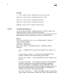
Example:
connect vlan 10 ethernet_port 10 ingress flow 12 flow_selector pbits default_flow 2
connect vlan 10 ethernet_port 10 ingress flow 13 flow_selector pbits default_flow 2
connect vlan 10 ethernet_port 10 ingress flow 14 flow_selector pbits default_flow 2
All the above commands do not have any significance for flows parameter. All the above commands will result in the same behavior of the traffic handling.
connect vlan 10 ethernet_port 10 ingress flow 12 flow_selector pbits default_flow 4
Glossary
The above command will throw an error message. So the default_flow should be one of the flows defined in connect command.
connect vlan 10 ethernet_port 10 ingress flow 15 flow_selector pbits default_flow 5
If default_flow is configured as >4 then behavior of the default_flow traffic is unknown.
In case the flow selector is defined as none, all traffic belonging to that vlan will experience the configuration of the connection flows.
4.11.3
Default Flow
One of the flows configured for the connection is the default flow. The default flow accepts the packets that do not match the flow selection criteria. When DSCP is the flow selection criteria on the connection, it is important to configure a default flow. All the nonIP traffic is forwarded to the default flow, since nonIP packets do not contain the DSCP field, for example, ARPs and PPPoE packets. When pbit is the flow selection criteria on the connection, the default flow will be used for untagged traffic.
All the other packets, which contain the configured flow selection criteria, are forwarded to their corresponding flows. 4.12
IPsec
The EFN324 in R. 4.3, inline with the EDA products, support the IPSec. The IPSec can be enabled or disabled depending on the option 43 message of the DHCP ACK message. The IPSec implementation is based on Wind River Linux.
The IPsec feature on the EFN324 can be enabled or disabled without restarting the node; the feature is active or inactive depending on the option 43 information of DHCP ACK.
In case IPSec is enabled, the RS232 connection is blocked.
In case the IPSec option is enabled, the software download might be significantly slower, e.g. 40% slower then usual.
IndexIndex
4.12.1
Enabling of IPSec
IPSec is enabled after the reception of a DHCP ACK message from the DHCP server with the option43 contains the string “:01:EMPMAC”.
If the option43 value contains the vendorencapsulatedoptions from the DHCP server and the IPSec flag set (first bit of the 4th parameter set), it indicates IPSec is enabled in the network. E.g., "172.31.25.21:Configuration.cfg:172.31.64.50:01:EMPMAC”.
4.12.2
Monitor IPSec connection
Once the EFN is in IPSec Enabled state, periodic ping requests are sent towards the EMP every 60 seconds (using ipseccontrol verify). If there is no response from the EMP for three consecutive ping requests (180 seconds), the IPSec connection is considered as failed and IPSecMonitorFailed event is generated.
4.12.3
Fallback to restarting DHCP
IPSec negotiation can be restarted by doing a new DHCP discover this implies that state will fallback to idle. The fallback to idle is implemented by reusing the code that is executed when a DHCP renew fails (basically stop and start DHCP). As next DHCP offer may not set IPSec, then the key is deleted to protect it.
At no time a fallback to idle will cause interruption of the user traffic on the nodes. Only management traffic may be interrupted. The EFN324 is able to restart the DHCP sequence from DHCP Discover by restarting the DHCP client. When the DHCP is restarted then the normal procedure is followed depending on if “IPSec” string is present in the DHCP option 43.
The CLI command “set cpu restart_dhcp start” can be used to restart the DHCP client in EFN.
The CLI command “get cpu ipsec_status” will give the ipsec status in EFN. Weather the IPSec is enabled or disabled in EFN. Glossary
5
Switching Functions
Switching refers to all the rules and mechanisms in the EFN324, which collectively decide what will happen to a packet which arrives at a certain port:
Will the packet be discarded, or will it be forwarded?
To which port, or ports, will it be forwarded?
Will the content be modified, and if so, how? All available switching mechanisms are described in the following sections, starting with basic switching mechanisms and ending with options like IP validation, Quality of Service and so on.
5.1
Main Switching Steps
When a packet arrives at an Ethernet port, the main question is whether there is a matching ingress connection. If not, the packet is discarded. If there is a matching connection, the packet is forwarded to the switching domain identified by that connection.
Ethernet
port
?
switching domain
Figure 13 Incoming packet
VLAN ID = x
?
switching domain
Is there an ingress connection for VLAN ID = x ?
?
switching domain
Ingress port switching
Similarly, when the packet arrives at a switching domain, the main question is whether there is a matching egress connection. IndexIndex
The ingress port switching described above is based on VLAN ID (or on VLAN ID and IP destination address), including when the packet is untagged or has double VLAN IDs (if QinQ is used). However, the egress port switching domain switching is based on destination address. See Figure 14 on page 28. Incoming packet
VLAN ID = x
dest. addr = y
Is there an egress connection with dest. addr. = y
Ethernet
port
?
?
?
?
Switching domain
Figure 14 Switching domain switching
The EFN324 has optional functions in addition to the basic Layer 2 switching, in order to increase the security. These additional features are described under the concept Forced Forwarding, in section 8.1 on page 60. The final processing is done at the egress port. The packet is placed in one of four priority queues and sent in the order decided by the scheduling algorithm.
Capacity limits are checked at the egress ports and, to a certain extent, at the ingress port switching. Capacity limits are either configured bandwidth limits or physical link and buffer capacities. Violation of capacity restrictions is one reason why the switch can discard a packet. In summary, switching consists of these three main steps: 1.
At the ingress port, find an ingress connection and a switching domain.
2. At the switching domain, find an egress connection. For multicast and broadcast, find the egress connections.
3. At the egress port, find the right opportunity and send the packet.
Glossary
Each of these steps is described in more detail in the following sections. Quality of Service is described separately in section 5.5 on page 39.
5.2
Ingress Port Switching
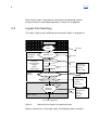
The steps in ingress port switching are illustrated in Figure 15 on page 29. Layer 1
Arriving frame
FCS
error?
Introductory
’classification’
and checks
Null DA, PAUSE etc.?
broadcast/
multicast/unicast,
untagged/
tagged/
double tagged
Ingress
switching
Discard
Discard
Bridge and STP port state?
Discard
Depending on port state:
BPDU?
internal
processing
No connection
Connection to
vlan exists?
Depending on configuration
internal
processing
ARP, DHCP, IGMP?
Filtering Discard
Change DA
Filtering?
(optional)
Discard
Quality of Service
To host port,
ethernet link port or switching domain
To switching domain
Figure 15 Detailed Path from Ingress Port to Switching Domain
When a frame arrives at the ingress port, the following actions are taken:
IndexIndex
1.
Frame Check Sequence (FCS)
When a frame has successfully been extracted in Layer 1, the Frame Check Sequence (FCS) is recalculated in order to detect biterrors. Frames with detected biterrors are discarded. The introductory 8byte preamble and the ending 4byte FCS are peeled off, and then the packet is delivered to Layer 2. 2. Null Addresses
All packets, unless discarded in earlier phases, are checked against the basic requirements before further processing. Invalid packets are discarded. These are the basic requirements for valid packets:
Layer 2 destination address may not be null.
Layer 2 source address may not be null.
Layer 2 source address may not be a multicast type address.
3. PAUSE Message
If the frame is a Layer 2 PAUSE messages, intended for Layer 2 flow control, it is discarded. 4. Port and Bridge States
The processing at Layer 2 depends on the bridge state and the port state. The states are determined based on either the operator configuration, or EFN324 internal algorithms processing BPDUs (see the next step). When the bridge or port is disabled, there is no further processing and the packet is discarded immediately. Packets are also discarded when the Spanning Tree Protocol (STP) or Rapid Spanning Tree Protocol (RSTP) is in a blocking, listening or learning state. However, in the learning state, the bridge table is updated, according to the contents of the validated packet.
5. Bridge Protocol Data Units (BPDU)
Configuration BPDUs, that is, configuration messages sent by STP or RSTP, are extracted from the stream of packets arriving at a port. They are processed by the EFN324 itself. This processing of BPDUs is unconditional and performed in all states. Glossary
Implementationwise, the processing of BPDUs is done in the host processor. BPDUs are forwarded to the host regardless of whether any connection is defined from this port through a switching domain to the host port. 6. Packet Type The packets are classified as multicast or unicast. Packets are also classified by the number of VLAN Tags in the packet. Untagged, single and double VLAN Tags may be handled. 7.
ARP, DHCP, IGMP
ARP, DHCP and IGMP control messages will, depending on the configuration, be extracted for internal processing. For instance, ARP messages are extracted for internal processing as soon as a gateway is defined or a switching rule is set different from normal. The EFN324 acts as ARP proxy for a specific switching domain. In cases where these control messages are not extracted for internal processing, they are switched in the same way as other packets.
8. Connection to Switching Domain
After the introductory checks and classifications, the actual switching work begins. The ingress port switching work consists of the search for an existing connection from the ingress port to a switching domain. This search is based on VLAN IDs. If the packet is untagged, there must be an ‘untagged connection’ on which the packet can be forwarded. If there is no matching connection, the packet is discarded. The configuration software ensures that there can be only one matching connection. An error message appears whenever an operator tries to define an ambiguous connection.
9. Filtering
Filtering is an optional feature. It can only be configured from the CLI, and not using SNMP. Filtering makes it possible to specify filter conditions for the Ethernet destination and source addresses, as well as for the Ethernet type field. Filtering can be performed for unicast and broadcast packets only, not for multicast packets. IndexIndex
When a connection is found, the EFN checks whether a filter is associated with the connection. If so, the packet header content is checked against the related global_filter resources and the actions according to the chosen filter_profile are taken. Up to 8 filter_profiles can be defined.
Each filter_profile has 8 attributes, named global_filter_1 to global_filter_8. global_filter_1 refers the action to be taken based on the result of the global_filter object, global_filter 1. Global filter objects do not have an underscore between global_filter and their index number. Similarly, global_filter_2 refers to the action to be taken based on the result of global_filter 2, and so on.
Matching starts with global_filter_1. If the matching is positive, that is, the packet header content is consistent with global_filter 1, then the measures specified at global_filter_1 are taken. When matching gives a positive result, the other global filters are skipped. If the match is negative, matching will continue with global_filter 2.
If matching with global_filter_N is negative, then matching with global_filter_N+1 is done, and so on, until either a positive match is made or all 8 global_filter have been tested. In the latter case, the actions defined for global_filter_none are performed. The possible filtering outcomes are the following:
The destination address is changed.
The packet is discarded.
The packet is forwarded directly to an egress port or a switching domain.
The packet is allowed through for further processing, according to the normal procedure.
10. Quality of Service
Quality of Service functions are performed as described in section 5.5.1 on page 42.
5.3
Switching Domain When a packet arrives at the switching domain, the main issue is to decide where to send the packet. Specifically, to which egress connection, or connections, is the packet forwarded?
Glossary
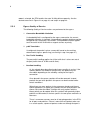
A normal outcome is that the packet is forwarded to one and only one of the egress connections of the switching domain. The outcome might also be that the packet is not forwarded to any egress connection, that is, the packet is discarded. The packet may also be forwarded to more than one egress connection. This is normal for multicast, but may also occur also for unicast and broadcast. The method used for the VLAN switching is determined by the switching rule configured for the switching domain. Switching rules are described in section 5.3.2 on page 35. First, however, topology concepts, including ‘uplink’, are introduced in section 5.3.1. These concepts are required to understand the switching rules, which include forced forwarding. This description of switching domain switching refers primarily to unicast packets. Multicast and broadcast are described in sections 5.3.3 on page 36 and 5.3.4 on page 37. 5.3.1
Internal Topology
When a packet is switched through a switching domain, connections to at least two separate ports must be defined: a connection from an ingress port and a connection to an egress port. A packet cannot be forwarded to the same port from which it arrived.
Every switching domain which carries traffic must be connected to a subset of the 26 available Ethernet link ports. Management traffic must be connected to the host port. A single port may be connected to more than one switching domain, as illustrated in the following figure.
Ports
Switching domain B
Switching domain R
Figure 16
Port – Switching Domain Connections
Each switching domain works as a separate switch for its connected ports. That is, when a packet arrives from a port at a switching domain, the switching domain will select one of its other connected ports and forward the packet to that port.
IndexIndex
In each switching domain, one of the ports can be designated as the ‘uplink’. Once an uplink is defined, all packets originating from other ports are automatically forwarded to the uplink. Packets originating from the uplink are forwarded in the same way as before. In this way, ‘uplink’ functions as one of many mechanisms supporting forced forwarding in single EFN324 nodes. An uplink may also be used when two or more EFN324 Ethernet access switches form a daisy chain. The ports connecting to the overlying EFN324 are designated as ‘uplink’. A port that connects to an underlying EFN324 is designated as ‘transit link’. To higher level aggregation
transit link
EFN324
EFN324
uplinks
Figure 17
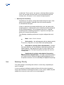
Daisy Chained EFN324 When transit links are defined, the switching domain switching rules are slightly modified. When no ordinary port is found to which to forward a packet that originates from an uplink, by default the packet is forwarded to the transit link. The EFN assumes if the packet destination is not found, that the receiver is located at a switch further down in the chain. Packets originating from a transit link are forwarded to the uplink. An uplink should be defined whenever a transit link is defined. The switching might however still work, even if no uplink is defined.
uplink
transit link
Ports
Switching domain B
Glossary
Figure 18 5.3.2
Switching Domain with Uplink and Transit Link
Switching Domain Switching Rule Modes
Each switching domain works according to one of the following switching rule modes:
Normal
Uplink
Uplink + GW
Uplink + IP validation
Uplink + GW + IP validation
Uplink + IP validation + virtual MAC
Uplink + GW + IP validation + virtual MAC
Uplink + PPPoE
The normal mode means that packets are switched according to the content in the bridge table. The bridge table content is maintained according to the selflearning bridge principle. When a destination address is not found in the table, the packet is forwarded (flooded) to all other ports in the switching domain. The effects of defining an uplink were described previously. When an uplink is defined, a gateway can also be defined. This is discussed further in section 8.1 on page 60. When a gateway is defined, all packets not originating from the uplink will have their destination MAC addresses rewritten as the MAC address of the gateway, before they are sent on the uplink. This mechanism is known as MAC forced forwarding. Packets arriving from the uplink must have the gateway as their source address in the Layer 2 network.
Please note that:
if the gateway is left undefined then DHCP and ARPs will be resolved for multiple end user in same port
if the gateway is configured then DHCP and ARPs will be resolved for multiple end user tags in same port only if multiple switching domains are used, i.e. unique switching domain should configure for that user tag; in other words, it is possible to have DHCP only for one user tag specific per port and per switching domain
o
in case each user needs several services it is necessary to configure a Switching Domain per service
IndexIndex
If IP validation is selected, the valid IP addresses for Endusers are defined. The establishment of valid IP addresses is described in section 8.2 on page 63. Switching towards Endusers is then based on IP addresses. Packets with unknown IP addresses are discarded, unless a transit link is defined, as described in section 5.3.1 on page 33. During IP validation, the source addresses of packets originating from the End
users are validated. Packets with invalid IP addresses are discarded. If Virtual MAC is selected, the Endusers’ MAC addresses are replaced with MAC addresses defined by the system, for all packets forwarded through the uplink towards the access network. These addresses are changed back to the original MAC addresses when packets are sent back on Enduser links. If PPPoE is selected, the Ethertype of the packets is checked. Packets without Ethertype 0x8863 or 0x8864 are discarded.
5.3.3
Switching Domain – Multicast
There are four options for handling multicast packets in a switching domain:
Yes – multicast packets are forwarded in the same manner as broadcast packets.
No – multicast packets are discarded.
IGMP Snooping – multicast streams are forwarded to subscribing End
user nodes. There is no suppression of IGMP messages. All messages and queries are forwarded.
IGMP Proxy – When EFN324 acts as IGMP proxy, it provides a total separation between the multicast network nodes and the Enduser nodes. When acting as IGMP proxy, the EFN324 fully suppresses IGMP messages. That is, none of the messages coming from the Endusers are forwarded. Multicast as Broadcast
When Yes is selected, IGMP snooping is not used. Multicast packets from nonuplink ports are forwarded to the uplink. Multicast packets from the uplink are broadcast to all other ports. Glossary
However, it is possible to prohibit broadcast on a specific egress connection. Multicast packets, which are distributed as broadcast, will not be let through on egress connections where broadcast_allowed is set to false. If no uplink is defined, multicast packets will always be broadcast when Yes is selected.
CLI Commands
Most multicastrelated settings are set using the set vlan command, since all multicast handling is done per switching domain. The following arguments are relevant to multicasting:
multicast {igmp_proxy|igmp_snooping|no|yes}
proxy_ip_address <IPaddress>
igmp_immediate_leave {no|yes}
igmp_query_interval <interval>
igmp_query_response_interval <interval> For detailed information on these commands, please refer to section 13.8.23 on page 141.
A related command is add connection vlan <vlan> ethernet_port <port> valid_multicast_groups <IP_address>, which is used to set the multicast addresses that the user is allowed to subscribe to. For detailed information on these commands, please refer to section 13.8.1 on page 107.
Displaying Subscribed Multicast Groups
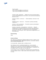
Using the get command with the resource vlan will display all multicast groups subscribed to for the switching domain. To view a single port, use get with the connection. 5.3.4
Switching Domain – Broadcast
By definition, broadcast packets are intended to reach all other stations on the network. Here, ‘the network’ is restricted to the virtual network defined by the switching domain. Accordingly, by default, every broadcast packet arriving at a switching domain is sent out on every egress connection, except the one to the port on which the packet arrived. Depending on the configured switching rule and forced forwarding mechanisms, forwarding of broadcast packets may be restricted even further.
IndexIndex
It is also possible to stop an egress connection from sending broadcast packets, by setting ‘broadcast_allowed’ in the egress connection to false. Broadcast packets are thereby totally eliminated on that connection.
5.4
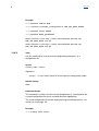
Egress Connection Functions
The egress connection functions are illustrated in Figure 19 on page 38.
From switching domain
Quality of Service
VLAN tagging
VLAN tagging
Priority based queuing and traffic scheduling
Egress Port
Figure 19 Detailed Path from Switching Domain to Egress Port
When the switching domain has decided to forward a packet on an egress connection, the following steps are performed before the packet is sent out on the egress port:
1.
Quality of Service
Quality of Service functions are performed, as described in section 5.5.2 on page 43.
2. VLAN Tagging
The packet is provided with the VLAN Tag, or tags, defined for the egress connection. Note that the outgoing packets may be ‘untagged’ so that the tags, if any, in incoming packets are removed. The outgoing packet is either untagged, single tagged or double tagged (QinQ). Configuring VLAN IDs to be handled as transparent is possible, and as a result, the VLAN IDs will not be changed. 3. Priority Based Queuing and Traffic Scheduling
Priority based queuing and traffic scheduling functions are performed, as described in section 5.5.2 on page 43. Glossary
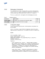
5.5
Quality of Service
When the same VLAN is used for traffic of different QoS requirement it is possible to use flows to differentiate how the traffic will be handled within the EFN. There will always be at least one flow created. If no flows are configured manually, a default flow will be created that will handle all the traffic in the specific VLAN. The QoS model implemented on the EFN324 in R4.3 is based on four QoS
Flows, configured at node level and one Flow per vlan. Frames are headed to the proper flow on the basis of the flow_selector parameter of the connect command, which can assume the values pbit, dscp, or none.
In the following is described the mapping in case of pbit or dscp.
Flow 1 – flow id values pbits 0, 1 or dscp 015
Flow 2 – flow id values pbits 2, 3 or dscp 1631
Flow 3 – flow id values pbits 4, 5 or dscp 3247
Flow 4 – flow id values pbits 6, 7 or dscp 4863
None is the default value; in this case, frames are headed to a unique connection flow per vlan.
In case none is the flow selector, all frames headed to this flow will receive the same handling, in other words there is no differentiation for the different CoS.
The following figure illustrates VLANs and Flow in the EFN between one downlink port and the uplink port.
IndexIndex
Upstream
output stream toward
the network port
Flow1
Flow2
Switching
Domain
VLAN 1
Flow1
Flow2
output stream toward
the user port
VLAN
1+2
Downstream
Port
VLAN
1+2
Port
Upstream
output stream toward
the network port
Flow1
output stream toward
the user port
Switching
Domain
VLAN 2
Downstream
Flow1
EFN324
Fi
gure 20
VLANs and Flows
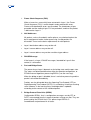
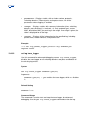
The Quality of Service steps are illustrated in the following figure. Each step is described in details in section 5.5.1 on page 42 and section 5.5.2 on page 43.
Glossary
Ingress
Port
VLAN
Bandwidth limitation
(configurable)
Discard
Flow selection
Ingress
Connection
Flow
1
Buffer space
available?
Discard
Flow 2
(flow) Priority
Marking
Switching
domain
Bandwidth limitation
(configurable)
Egress
Connection
Discard
Flow selection
Flow
1
Flow 2
P-bit translation
Overflow handling
Q
Highest
Q
High
Q
Medium
Scheduler
Egress
Port
Figure 21
Quality of Service la figura sopra è aggiornata!!!
Q
Low
Port traffic
handling
IndexIndex
5.5.1
Ingress Quality of Service The following Quality of Service actions are performed at the ingress:
1.
Connection Bandwidth Limitation
The packets are processed by the bandwidth limitation function for the connection. If the bandwidth limit is exceeded, the packet is discarded. The bandwidth limitation applies to all the incoming traffic of the VLAN with no regards to flow, or priority. 1.
Flow Selection
The flow to which the packet will be directed to is determined by the Flow selection criteria and the value of either pbit or dscp bit. The pbit/dscp bits are hard coded to the four global flows as given above. The following can be use as determination criteria (based on the packet header):
Pbit
DSCP
None (all traffic will be directed to the connection flow)
2. Quality of Service per Flow
For QoS processing, each packet is processed in the flow to which it belongs. For each flow, the following actions are performed:
The outqueue buffer memory is checked. If, for the flow reliability, the current remaining memory space is too low, the packet is discarded. Overflow situations might occur if, for example, a flow exceeding 100 Mbps from an uplink is directed to a single FE downlink. The buffer availability check is related to outqueue handling. Please refer to step 3 on page 43 for more information.
The ingress flow priority is used to assign the egress priority queue. The egress queue selection (queue Highest, High, Medium and low) is thus not dependent on the pbit of packet, but only depends on the priority configured for the ingress flow. See the dashed arrow line in Figure 21 on page 41, and step 3 on page 43.
The flow marking is determined, and is used in the egress pbit translation. For each flow, a pbit, to overwrite the existing pbit in the outer VLAN, can be configured. If Glossary
none is selected, the EFN handles the outer VLAN pbit transparently. See the dashed arrow line in Figure 21 on page 41, and step 2 on page 43.
5.5.2
Egress Quality of Service The following Quality of Service actions are performed at the egress:
1.
Connection Bandwidth Limitation
If a bandwidth limit is configured for the egress connection, the current bandwidth utilization is checked. If forwarding the packet would exceed the configured limit, the packet is discarded. The bandwidth limitation applies to all the traffic of the VLAN with no regards to flow, or priority. 2. pbit Translation
If configured, the packet is given a new pbit, based on the marking determined at ingress processing (see marking in step 2 on page 42 ). 3. Port Traffic Handling
The port traffic handling applies for all the traffic that is to be sent out of the port (traffic from all VLANs and all flows).
Overflow handling
As has already been described under ingress quality of service, if the memory buffers are filled over certain limits, the packet may be discarded, depending on the reliability setting for the ingress connection. Once placed in the queue, packets will not be removed. Instead, packets that are to be placed in the queue can be discarded under certain conditions. When there are many packets in the out queue already and the out queue approaches its upper limit, packets that are to be placed in the queue start to be discarded. To begin with, only packets with the lowest priority are discarded. After this, packets with gradually higher priorities are discarded, if the free space in the out queue continues to decrease. There is a common memory area for all outgoing packets in the EFN, for all ports and priorities. If there is more than one packet to be sent in a certain queue, a queue of packets to be sent through that port is IndexIndex
established. There are four ‘out’ queues, reflecting different priority levels, for each port. Because there is only one common physical memory area, all ‘queues’ in this context are logical queues.
Queuing and scheduling
Depending on the priority setting determined during the ingress flow processing, the packet is placed in one of the four outqueues associated with each port. If there is more than one packet waiting to be sent, the order of the outgoing packets is determined by the scheduling method configured for the switching domain. The next packet to be sent is selected according to the scheduling mechanism. In general, the higher the priority, the shorter the waiting time. The following scheduling mechanisms may be configured for each port:
None – that is, first in, first out.
Strict priority – the waiting packet with the highest priority is sent first, using first in, first out, within each priority group.
Weighted fair queuing (Deficit Round Robin) – packets with lower priorities are not completely held back by packets with higher priorities. Each priority class gets a certain share of the total sending time. The lower the priority, the lower the share of sending time.
Combined strict priority and weighted fair queuing (Modified Deficit Round Robin) – the highest prioritized packets are strictly sent first. When no highest prioritized packets are in the queue, the others are sent according to weighted fair queuing.
5.6
Marking Priority
The pbit marking or remarking takes effect in several ways, depending on how it is defined.
In case a marking is defined at node level flow, with the value transparent, frames will maintain the incoming pbit value. In case a tag is added, the pbit added will assume the same value as the incoming pbit.
Glossary
In case a marking is defined at node level flow, with a value between 0 and 7, frames will be remarked with the selected value. In case a tag is added, the p
bit added will assume the selected value.
In case a marking is defined at node level flow, with the value none, frames will be remarked as defined on the connect_vlan command.
5.6.1
Examples 1: trusted and untrusted users configuration
The following example describes a configuration with two different typologies of users configured on the node at the same time: the business users, which are trusted, and the residential users, which are untrusted. Traffic from the untrusted users shall be pbit remarked, while traffic from trusted users will maintain the original pbit tag.
For this scope the QoS Flows are explicitly defined as:
set connection_flow node_level flow 1 priority low reliability lowest marking transparent
set connection_flow node_level flow 2 priority medium reliability medium marking transparent
set connection_flow node_level flow 3 priority high reliability high marking 4
set connection_flow node_level flow 4 priority highest reliability highest marking 6.
Business customers will be tagged with vlan 500 through the Switching Domain 100, while residential customers will be tagged with vlan 600 and 700 through the Switching Domain 120 and 130.
Configuration of the business service on port 1 is defined as:
connect vlan 100 ethernet_port 1 ingress tags 500 flow_selector p-bit flows 1-3 default_flow 1
egress tag 500 p_tag none
connect vlan 100 ethernet_port 25 ingress tags 500 flow_selector p-bit flows 1-3 default_flow 1
egress tag 500 p_tag none
Residential users have two services, the Websurfing on vlan 600 and VoIP service on vlan 700; the configuration on port 1 is:
For the Websurfing service on vlan 600:
connect vlan 120 ethernet_port 1 ingress tags 600 flow_selector none egress tag 600 p_tag 0
connect vlan 120 ethernet_port 25 ingress tags 600 flow_selector none egress tag 600 p_tag 0
set connection_flow vlan 120 ethernet_port 1, 25 ingress flow 1 priority low reliability lowest
For the VoIP service on vlan 700:
IndexIndex
connect vlan 130 ethernet_port 1 ingress tags 700 flow_selector none egress tag 700 p_tag 5
connect vlan 130 ethernet_port 25 ingress tags 700 flow_selector none egress tag 700 p_tag 5
set connection_flow vlan 130 ethernet_port 1, 25 ingress flow 1 priority high reliability high
With this configuration, the traffic from the business users, from VLAN 500 is handled as:
frames tagged with pbit 0 or 1 will be headed to flow 1; the marking in QoSFlow_1 is defined Transparent, frames will exit with the original p
tag, i.e. pbit = 0 or pbit = 1
frames tagged with pbit 2 or 3 will be headed to flow 2; the marking in QoSFlow_2 is defined Transparent, frames will exit with the original p
tag, i.e. pbit = 2 or pbit = 3
frames tagged with pbit 4, 5 will be headed to flow 3; the marking in QoSFlow_3 is defined marking 4, so frames will exit with the modified pbit = 4
frames tagged with pbit 6, 7 will be headed to flow 4; the marking in QoSFlow_4 is defined marking 6, so frames will exit with the modified pbit = 6
For residential users, all traffic on VLAN 600 shall be remarked with pbit = 0, while all traffic on VLAN 700 shall be remarked with pbit = 5.
5.6.2
Examples 2: trusted and untrusted users configuration
This example describes a 3play configuration where traffic on the user side is single tagged and on the network side is double tagged; in the upstream direction the added tag will inherit the pbit tag from the user’s tag.
Global Setting:
set connection_flow node_level flow 1 priority low reliability low marking transparent
set connection_flow node_level flow 2 priority low reliability low marking transparent
Glossary
set connection_flow node_level flow 3 priority medium reliability medium marking transparent
set connection_flow node_level flow 4 priority high reliability high marking transparent
Configuration for the User 1 on port 1
set vlan 101 description Service1
connect vlan 101 ethernet_port 1 egress tag transparent p_tag transparent bandwidth_limitation 8
ingress tags 10-2399 flow_selector p_bits default_flow 1 flows 1-4
connect vlan 101 ethernet_port 25 egress tag transparent p_tag transparent second_tag 1001
second_p_tag transparent ingress tags * second_tags 1001 flow_selector p_bits default_flow 1
flows 1-4
set vlan 101 uplink ethernet_port 25
set ethernet_port 1 enabled yes
set connection vlan 101 ethernet_port 1 option_82_circuit_id undefined option_82_remote_id
undefined
set vlan 101 option_82 configurable
set bandwidth_limitation 8 bandwidth 100000
Traffic from the user side, Ctagged with values from 10 to 2399, will exit toward the network with the added Stag = 1001 and the same pbit in the C
tag. In the downstream direction the Stag will be stripped.
IndexIndex
6
Topologies
Topologies are the permissible physical configurations of EFN324 Ethernet access switches. Standalone and embedded EFN324 support different sets of topologies.
The topologies for Standalone EFN324 Ethernet access switches are described in section 6.1 on page 48.
The topologies for Embedded EFN324 Ethernet access switches are described in section 6.2 on page 50.
Note that link aggregation is not supported in any of the topologies.
For consistency, port 25 is used as the transit port, and port 26 as the uplink port in this section.
6.1
Standalone Topologies
EFN324 may be used as a standalone node. In other words, the EFN324 is not controlled by an ECN, but is instead controlled directly by PEM. Figure 22 on page 48 illustrates possible use scenarios for standalone EFN324 Ethernet access switches.
Aggregation
node
Aggregation
node
EFN
Endusers
EFN
Endusers
EFN
Endusers
EFN
Endusers
Aggregation
node
EFN
Endusers
Daisy Chained
Figure 22
Aggregation
node
Standalone EFN324 Use Scenarios
EFN
EFN
EFN
Endusers
Endusers
Endusers
Rapid Spanning Tree
Glossary
The Switch ID for standalone EFN324 Ethernet access switches is always zero (the default value). In other words, standalone EFN324 Ethernet access switches are never configured as flexible blocks.
6.1.1
Standalone EFN324 Ethernet access switches
No additional CLI commands are required in the EFN324 in order to use it as a standalone node which is not daisy chained.
6.1.2
Standalone Daisy Chained
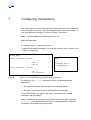
The initial configuration of the EFN and the command to configure a daisy chain are included in the EFN324 Installation Guide. See section 5.3.1 on page 33 for information on configuring ports to accommodate Daisy Chained topology. To enable traffic, the operator must configure the chain, using the following CLI command in each EFN324:
set vlan 1 transit_link ethernet_port 25 uplink ethernet_port 26
Note that this example assumes that the management vlan is vlan 1.
Figure 23 on page 49 illustrates the effect of the CLI command on the port configuration in the daisy chain. Ports marked T are configured as transit link ports, while ports marked U are configured as uplinks.
Uplink
Transit
Transit
EFN324
Figure 23
25 26
T U
EFN324
25 26
T U
EFN324
25 26
T U
Port Configuration in EFN324 Daisy Chain
PEM enables the chain for other switching domains by configuring the VLANs in the chain, as needed.
Quality of Service flows will only be configured in the EFN which the Enduser is connected to. In the other EFN Ethernet access switches in the chain, the IndexIndex
QoS is best effort, in other words, with the lowest of each QoS parameter. However, where an Enduser with the same service is configured in the other EFN Ethernet access switches, the QoS parameters for that service are used.
6.1.3
Standalone Rapid Spanning Tree
The standalone daisy chained requirements also apply to standalone rapid spanning tree. After entering the standalone daisy chained CLI commands, enter the following commands in each EFN to configure Rapid Spanning Tree:
add rapid_spanning_tree 1 ports ethernet_port 25
add rapid_spanning_tree 1 ports ethernet_port 26
In the CLI commands above, 1 is used for the instance ID for the RSTP. The same value is used for all the uplink ports on all the EFN Ethernet access switches in the Rapid Spanning Tree.
In addition, see section 9.1 on page 72 for information on using Rapid Spanning Tree.
6.2
Embedded Topologies
EFN324 may also be used as an embedded node. In other words, the EFN324 is part of an Ethernet Access Node (EAN) and is managed via an ECN, instead of directly by PEM. The following basic requirements apply to every embedded EFN324:
To be recognized as an embedded node, the EFN324 must be configured as a flexible block, with a Switch ID number. In addition, the EFN324 must obtain its IP address using DHCP, and the management VLAN must be configured in switching domain 1.
The EFN324 Ethernet access switch(s) uplink must be connected to a Gigabit port. If the EFN is connected directly to an ECN330, this means that only ECN330 uplink ports may be used. However, if the EFN is connected directly to an ECN430, any port may be used.
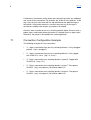
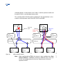
Figure 24 on page 51 illustrates the use of the EFN324 as an embedded node. Note that the EFN324 Ethernet access switches can be connected directly to the ECN330 or ECN430 and do not have to be connected via an unmanaged network. Glossary
ECN330 or 430
ECN330 or 430
Unmanaged
Network
EFN324 SID=35
Endusers
Endusers
Unmanaged
Network
ESN212
EFN324 SID=23
ECN330 or 430
Unmanaged
Network
SID=1
EFN324 SID=2
EFN324 SID=3
EFN324 SID=42 EFN324 SID=43
Endusers
Endusers
Endusers
Embedded Flexible Blocks
Using an ESN212
Flexible Block Uplink
Figure 24
6.2.1
Endusers
Daisy Chained
Embedded EFN324 Use Scenarios
EFN324 as Embedded Flexible Blocks
Only the basic requirements listed previously, in section 6.2 on page 50, apply to these nodes. 6.2.2
Using an ESN212 Flexible Block Uplink
EFN324 embedded flexible blocks can be connected directly to an ESN212 flexible block, as shown in Figure 24 on page 51. In addition to the basic requirements, the EFN324 must be connected to an uplink port on the ESN212 (ports 9, 10, 11 or 12). This means that a maximum of three EFN324 Ethernet access switches can be connected directly to an ESN212 flexible block, since the ESN212 requires at least one uplink port to use as its own uplink.
6.2.3
Daisy Chaining Embedded Flexible Blocks
EFN324 embedded flexible blocks can be daisy chained to each other, as shown in Figure 24 on page 51.
The following restrictions apply to daisy chained embedded EFN324:
IndexIndex
No other types of flexible blocks or nodes can be included in the chain, or send traffic through the EFN324.
Only one uplink is permitted from the daisy chain. Rapid spanning tree is not supported for embedded daisy chained EFN324 Ethernet access switches.
The EMP and PEM do not know the order in which the EFN Ethernet access switches are connected. The EMP and PEM simply see each EFN Ethernet access switch as an independent flexible block.
PEM only configures the service VLANs on the EFN that the Enduser is connected to. In EFN Ethernet access switches where the service VLAN is not configured, the traffic is handled by the transit switching domain.
PEM only configures Quality of Service on the EFN that the Enduser is connected to. In the remaining EFN324 Ethernet access switches, traffic is forwarded as “best effort”, in other words, with the lowest of each QoS parameter.
A transit switching domain must be configured manually in the Ethernet access switches. VLAN 2 is reserved for this. A transit link for the management VLAN switching domain must also be configured. More information on this is given in the CLI commands below.
The initial configuration of the embedded EFN and the configuration of a daisy chain are included in the EFN324 Installation Guide. To configure the uplink and transit link for the management VLAN for the chain, enter the following commands in each EFN:
set vlan 1 transit_link ethernet_port 25 uplink ethernet_port 26
To configure a transit switching domain manually in the Ethernet access switches, enter the following commands in each EFN, except the last EFN in the chain:
set vlan 2 description transit
set node_control default_vlan vlan 2
connect vlan 2 ethernet_port 25,26
set vlan 2 transit_link ethernet_port 25 uplink ethernet_port 26
Glossary
Note that if the above commands are also entered in the last EFN in the chain, this will not cause any problems.
Figure 25 on page 53 illustrates the effect of the CLI commands on the switching domain configuration in the daisy chain. Ports marked T are configured as transit link ports, while ports marked U are configured as uplinks.
The figure also shows the service switching domains, labeled x and y, configured automatically by PEM. ECN330 or 430
Configured manually
26
U
U Uplink port
T Transit port
D Downlink port (to Endusers)
Figure 25
Configured by PEM
Transit
Uplink
EFN324 25
T
VLAN
1
VLAN
2
D
26
U
VLAN y
EFN324 25
T
VLAN
1
VLAN
2
VLAN x
D
Switching Domains in Embedded Daisy Chained EFN324
IndexIndex
7
Configuring Connections
This section gives a more detailed picture of how connections are used in the CLI in the form of resources, attributes and commands. Note that the term tag may have different meanings, as shown in Figure 7 on page 15. Note:
Switching domain is called vlan in the CLI.
When the command # connect vlan 2 ethernet_port 2
is entered, the following attributes are set in the ‘ethernet_port 2’ and the ‘vlan 2’ objects respectively: ethernet_port 2
…
# ingress_connections Key Value
...... ......
vlan 2
tags all
…
# egress_connections Key Value
...... ......
vlan 2
tag transparent
…
Figure 26 vlan 2
…
# incoming_ports 2
# outgoing_ports 2
…
Contents of Port and Switching Domain Objects Defining Connections By default the CLI connect command creates the following twoway connection:
An ingress connection from the port to the switching domain.
An egress connection from the switching domain to the port. (In the MIB interface, the egress and ingress connections are created separately from each other.)
When a packet arrives at a port, there must be at least one path, called the connection here, leading from the port to a switching domain. Otherwise, the packet is discarded at the ingress port.
Glossary
Furthermore, the contents of the packet must be consistent with any additional rule set up for the connection. For example, the VLAN ID in the packet’s VLAN tag, if any, must be consistent with the tag definition for the potential ingress connection. If the packet content is not consistent with any of the ingress connections leading from the port, the packet is discarded.
Likewise, when a packet arrives at a switching domain object, there must be a proper egress connection before the packet is switched out on an egress port. Otherwise, the packet is discarded at the switching domain.
7.1
Connection Configuration Example
The following example has five connections:
Ingress connection from port 2 to switching domain 2. Only untagged packets. (“tag = untagged”)
Ingress connection from port 2 to switching domain 3. Only tagged with VLAN ID 2, 3 or 4. (“tag = 2, 3 or 4”)
Egress connection from switching domain 2 to port 5. Tagged with VLAN ID 22. (“tag = 22”)
Egress connection from switching domain 3 to port 7. Transparent VLAN ID. (“tag = transparent”) Destination address A.
Egress connection from switching domain 3 to port 9. Transparent VLAN ID. (“tag = transparent”) Destination address B. IndexIndex
n
_p
et
7
rt
o
5
rt
o
2
rt
o
_p
et
tag
transparent
Dest A
3
1
2
4
tags
untagged
tag
transparent
Dest B
5
tags
2-4
vlan 2
Figure 27
9
rt
o
_p
et
n
er
h
et
er
h
et
n
_p
et
n
er
h
et
er
h
et
tag 22
vlan 3
Example of Ingress and Egress Connections
Table 5 on page 56 shows the switching behavior which results from the connections illustrated in Figure 27.
Table 5
Examples of Switching Behavior
Incoming packet
Switch decisions
Untagged.
Forwarded to switching domain 2, from switching domain 2 forwarded to port 5. A VLAN Tag with VLAN ID 22 is inserted in the packet.
VLAN ID equal to anything but 2, 3 or 4.
Packet discarded at ingress port.
VLAN ID equal to 2, destination address A.
Forwarded to switching domain 3. Switching domain 3 forwards the packet to port 7. The VLAN Tag is untouched (‘transparent’). VLAN ID equal to 2, destination address B.
Forwarded to switching domain 3. Switching domain 3 forwards the packet to port 9. The VLAN Tag is untouched (‘transparent’).
Glossary
Incoming packet
Switch decisions
VLAN ID equal to 2, destination address C.
Forwarded to switching domain 3. Switching domain 3 floods the packet to both port 7 and to port 9. The VLAN Tag is untouched (‘transparent’).
The last row in Table 5 is an example of flooding. Flooding may occur when a switching rule is set to ‘normal’. If forced forwarding is configured, flooding is restricted. Note that switching domain number is the number of the switch domain object. Do not confuse this with the VLAN ID located inside the VLAN Tag.
At configuration, when specifying connections in the CLI, the EFN324 checks the consistency of the latest command against the commands issued earlier. The command is rejected if inconsistencies are found. Therefore, an actual configuration is always correct from the switching logic point of view. It is up to the operator to ensure that it is also correct from a traffic point of view.
7.2
The Connect Command
The previous section gave the basis for defining connections through the EFN324 switch. A connection is defined using a connect command, which targets the resource object types ethernet_port and vlan. In addition, the flows within each connection are assigned.
Note that the resource object type connection is not directly involved. The connection object may be seen as a container of additional attributes, which specify how IP validation, multicast and Option 82 are handled on the connection in question.
The syntax of the connect command is:
# connect vlan M (1 – 200) ethernet_port N (1 – 26) OPTIONAL PARTS
The optional parts are:
ingress followed by a subset of the following:
Attribute
Description
bandwidth_limitation
Specifies bandwidth limitation at ingress.
IndexIndex
description
Optional text.
filter_profile
Specifies filter conditions.
flow_selector
Assigns specific pbit or DSCP values to specific flows.
ip_destination
Specifies which IP addresses the Endusers can use as IP destination address. tags, second_tags
Specification of allowed VLAN IDs for incoming packets. The option ‘untagged’ is also available.
egress followed by a subset of the following: Attribute
Description
bandwidth_limitation
Specifies bandwidth limitation at egress.
broadcast_allowed
Specifies whether broadcast packets are forwarded.
description
Optional text.
first_ethertype,
second_ethertype
The ethertype used on the outgoing frame. It can be transparent, thus using the value from the received VLAN tag, or it can be set to a predefined value.
flow_selector
Assigns specific pbit or DSCP values to specific flows.
p_tag, second_p_tag
Specifies the priority bits in the VLAN Tags to be set for outgoing packets. The options ‘transparent’ and ‘untagged’ are also available.
tag, second_tag
Specifies the VLAN IDs to be set for outgoing packets. The options ‘transparent’ and ‘untagged’ are also available.
The resource objects and commands involved in configuring connections are summarized in Figure 28 on page 59. Glossary
ethernet_port
ethernet_port
set connection
option_82_circuitID
option_82_remoteID
multicastgrouplimit
add connection
static_IP_Addresses
valid_multicastgroups
(White list)
set connection flow
egress
set connection flow
ingress
flow_identifying_values
reliability, priority
bandwidth_limitation
burst_tolerance
policing_action
marking
Connect ingress
vlan – index 1..200
tags, second_tagsVLAN ID
IP Destination
bw_limit
filter_profile
flow_selector
Figure 28
EFN324
set connection flow
egress
flow_identifying_values
bandwidth_limitation
burst_tolerance
Connect egress
vlan – index 1..200
tag, second_tag – VLAN ID
p_tag, second_p_tag
bw_limit, flow_selector
broadcast_allowed
set vlan
switching_rule, gateway
Uplink, transit_link – port no (daisy chain)
ARP and DHCP tag – parallel VLAN ID
gateway (forced forwarding configuration)
mac_address_learning
max_dynamic_ip_addresses
max_virtual_mac_addresses
Multicast, IGMP, DHCP options
Switching domain
Connections Related Commands and Resources
set connection flow
ingress
IndexIndex
8
Security Functions
Basic switching is focused on the task of distributing packets to whoever wants them. In a Public Ethernet Environment there are strong requirements that packets are not delivered to unauthorized receivers. Packets could be delivered to unauthorized receivers due to verbose switching mechanisms like broadcast, by faulty configurations, by manipulations by hostile users, and so on. This section describes the security mechanisms offered by the EFN324.
Note:
8.1
Some of the security measures are dependent on others. That is, they cannot be activated unless other security measures are activated.
Forced Forwarding
Forced Forwarding is a security measure that may be added on top of basic switching mechanisms in order to enhance security. In an access network, one such measure is to force uplink packets up to an edge node, instead of switching the packets directly to another Enduser, using the shortest path. This way, there is a Layer 2 separation from Enduser to Enduser and End
user to Access nodes.
Forced forwarding offers additional restrictions on switching compared to the ‘normal’ switching in the EFN324. Forced forwarding may be defined with a gateway to which all packets are forwarded.
The connect command is used to configure forced forwarding in the EFN324. Attributes in the ‘vlan’ (switching domain) and ‘connection’ resources will show how forced forwarding has been configured. Forced forwarding is enabled by specifying an uplink for a switching domain. Additional security mechanisms may be configured as needed.
8.1.1
Define Uplink
The first step is to define an ‘uplink’ in the switching domain. Packets arriving on links other than uplinks are forced to the uplink. Glossary
Uplink is defined as an ethernet_port number. A connection must also be defined from the switching domain to that port before packets may be forwarded to the uplink.
Note that this measure alone will not always force packets up to the border node. Intermediate aggregation switches in the Access network might forward the packet according to the destination address of the packet, before it reaches the border node. In order to ensure that packets reach the border node, a gateway for forced forwarding is needed as well.
8.1.2
Define Gateway
The second step is to define a gateway. Note: a gateway is not needed to enable either IP validation or virtual MAC, which are described later.
Uplink packets, which are not addressed to the gateway, are discarded. Downlink packets with other source addresses are also discarded. Note that the Layer 2 MAC addresses are checked here. The Layer 3 IP addresses are not checked here.
If these checks are not made, a packet sent from one Enduser, directed to a neighbor connected to the same or a neighboring EFN324, will first be forwarded through the uplink to an aggregation switch. This switch can potentially forward the packet directly to the EFN where the intended receiver is located, rather than towards the border node. That EFN will then unsuspectingly forward the packet to its destination. So, in order to ensure that all packets pass the border node, in addition to an uplink, a gateway should be defined.
Note:
8.1.3
Multicast packets are not subjected to the source address check.
ARP Proxy
The configuration of a gateway automatically activates an ARP proxy function in the EFN324. The ARP proxy answers all ARP requests from Endusers, with the MAC address of the gateway. As a result, all packets from Endusers have the gateway as their Layer 2 destination. All other uplink packets are discarded.
IndexIndex
ARP requests from the gateway (all other uplink sources are discarded) are only forwarded to the Enduser with the IP address in the ARP request. The response from the Enduser will also be forwarded.
8.1.4
ARP Handler
The ARP Handler allows the EFN324 to increase the ARP Processing Performance. The EFN324 will discard the ARP requests received on the uplink with a source MAC that is not equal to that of the gateway. This feature is enabled when the switching domain is configured with switching rule = ip_validation or virtual_mac. This is done to avoid processing ARPs that are not relevant to the EFN. Improved handling of the ARPs is achieved by forwarding the ARPs to the Host if, and only if, the Client IP address is already known. Previously, some of the ARPs sent by the Host to the Clients may not have been answered because they were not destined for those Clients. The EFN now first verifies the Target Protocol Address of the ARPs from the Gateway and then forwards them to the Host for more processing. The Host load of unnecessary ARPs is thus reduced. This feature is enabled by default when the switching rule of the switching domain is configured as ip_validation or virtual_mac.
The feature can be disabled by setting the switching domain parameter, check_gateway_source_address to no. The use of the command is described in section 13.8.23 on page 141.
8.1.5
Configuration
Set an ‘uplink’ in ‘vlan’. The ‘switching_rule’ is still set to ‘normal’ here.
As has been described above, a gateway may be defined for a switching domain. Different switching domains may have different gateways. The MAC address of the gateway is primarily used by the forced forwarding function. Besides directly specifying a MAC address (option 1 below), the gateway MAC address may also be retrieved with help of ARP (options 2 and 3).
The gateway is configured by setting the ‘gateway’ attribute in ‘vlan’ to one of the following three alternatives:
1. In the form of a MAC address which completes the definition of the gateway. It is not necessary to retrieve the GW IP address for this option. Forced Glossary
forwarding mechanisms utilize the MAC address. The IP address is only needed as a means to, through ARP, retrieve the MAC address.
2. In the form of an IP address. For this option, the EFN324 must send an ARP to retrieve the gateway MAC address. This is described in more detail below. 3. As auto. For this option, the gateway IP address is snooped from the DHCP ACK message directed to the Enduser who first issued a DHCP request. After this, the gateway MAC address is retrieved in the same way as in option 2. If, in option 3, all downlink messages in the access network originated from the gateway, the gateway MAC address could be retrieved from any downlink message. However, this may not always be the case. The DHCP traffic may enter the access network elsewhere. Therefore the gateway MAC address must be retrieved using ARP.
The switching domain resource attributes ‘ip_address’ and ‘mac_address’ are introduced as an option, so that the operator can provide the EFN324 with the switching domain specific address to be used as sender in the ARP request. By default, these attributes are ‘auto’. At ‘auto’ the IP or MAC address is snooped from the first available ARP, IGMP or DHCP message from a client, and ‘borrowed’ for use in the own ARP request. The attributes borrowed_ip_address and borrowed_mac_address (in the switching domain resource) are status information about the sender source addresses that the EFN324 uses in ARP requests.
8.2
IP Validation
Another security measure is IP validation. That means that IP addresses are also checked during forwarding decisions for unicast packets. Multicast and broadcast are treated according to special rules. Note:
This feature can only be used if forced forwarding is activated.
Enduser IP addresses are validated per port. That is, only upstream packets with the Enduser IP source addresses and downstream packets with End
user address as destination addresses are let through. All other packets are discarded.
IP source address validation, also called IP source address filtering, aims to stop malicious Endusers from sabotaging the network. The socalled SYN IndexIndex
attack, where high numbers of TCP SYN messages are sent towards a host in order to drain its execution capacity, is an example of attack that may be stopped. IP source address filtering immediately stops packets with false IP source addresses. The EFN324 gets information about valid IP addresses in two ways. Static IP addresses can be configured for each Enduser by the operator. Alternatively, the EFN324 learns IP addresses dynamically by DHCP snooping. The two methods do not exclude each other, since it is possible to simultaneously have both static and dynamic addresses for an Enduser. 8.2.1
Configuration of IP Validation
Set ‘switching_rule’ to ‘ip_validation’ in ‘vlan’. Also set an ‘uplink’ and optionally a ‘gateway’.
Valid IP addresses may be ‘static’ or ‘dynamic’. Static addresses are added to, or removed from, the connection object using add and remove commands. For example:
# add connection vlan 1 ethernet_port 1 static_ip_addresses <IPv4ADDRESS>
Dynamic addresses are learned by the EFN324 by snooping DHCP ACK messages on their way from the DHCP server to the Enduser. It is possible to set a maximum number of dynamically learned IP addresses that can be set and saved per switching domain and Enduser port.
Both static and learnt IP addresses may be read out from each connection object. Setting max_dynamic_ip_addresses to zero means that dynamic IP addresses are not allowed. In that case static IP addresses must be defined. Note that static IP addresses may be defined even though dynamic IP addresses are allowed.
8.2.2
IP Validation to Host Port
IP validation, and other forced forwarding mechanisms, are primarily intended for use on Enduser connections. IP validation may also be applied on connections to the host port. This is, however, unnecessary. The host is an internal system function and must be considered ‘safe’. In addition, the use of a Management VLAN, see section 10.3 on page 79, eliminates the need for extra forced forwarding security mechanisms. Glossary
Note also that the host port does not send DHCP requests to get its IP address. The host port IP address must be configured manually. Therefore IP validation with dynamic IP addresses would not work. The same situation may occur for Endusers who receive their IP addresses by means other than through DHCP. In those cases, IP validation must be configured with static IP addresses. 8.3
Virtual MAC
Virtual MAC (VMAC) address is a security feature that replaces the Enduser’s original MAC addresses with a MAC address controlled by the system, before forwarding the packet to the access network. A packet to the Enduser has the VMAC address as its destination within the access network, but this is replaced, by the EFN, with the original MAC address before the packet is sent to the Enduser. Using VMAC protects against Ethernet address spoofing. That is, when an Enduser deliberately uses another Enduser’s MAC address, to trick the self
learning Layer 2 address mechanism in the switch, in order to access information sent to the other Enduser or to hinder that Enduser’s access to the network. The VMAC also makes the Layer 2 address configuration more fault tolerant. Endusers behind different ports may be given identical MAC addresses, without endangering correct routing within the access network. Note:
This feature can only be used if the switching rule is IP validation and if Forced Forwarding is activated by specifying an uplink. A gateway can optionally also be specified.
A MAC address consists of 48 bits or 6 octets. The separator sign is usually a colon (“:”). A virtual MAC address is an extended use of the IEEE specification for the local MAC address format.
The VMAC format is depends on whether the EFN324 is a standalone (managed only by PEM) or an embedded (managed by an ECN) Ethernet access switch. These are described separately in the following subsections.
8.3.1
VMAC for a Standalone EFN324
The VMAC address that the system allocates to each Enduser is based on the Enduser port number, switching domain ID and EFN324 identity. IndexIndex
Table 6
6 bits
Domain Value
Virtual MAC Address Format for a Standalone EFN324
2 bits 8 bits
10
8 bits
Index Port Number
8 bits
16 bits
Switching Domain Number
EFN324 ID
Parameters:
Domain value is 0x00 for a standalone EFN324.
10 indicates that the MAC address is a locally administered unicast address.
Index is the incrementing number per allocated VMAC address. A maximum of 256 virtual MAC addresses are allowed per port and VLAN (range 0 to 255).
Port number is the physical port on the EFN324 to which the Enduser is connected (range 1 to 26).
Switching Domain number is the logical number assigned to the switching domain used for the connection (range 1 to 200).
EFN324 ID is the last 2 bytes from the EFN MACaddress.
Configuration of Virtual MAC for a Standalone Node
Set eda_vmac_format to no.
Set ‘switching_rule’ to ‘virtual_mac’ in ‘vlan’. Also, set an ‘uplink’ and optionally a ‘gateway’.
When setting the switching rule in the CLI to ‘virtual_mac’, IP validation is automatically activated. The assigned virtual MAC addresses are status attributes in the connection resource.
Suggestion: set max_virtual_mac_addresses to max_dynamic_ip_addresses plus the number of defined static IP addresses.
Glossary
8.3.2
VMAC for an Embedded EFN324
The VMAC address that the system allocates to each Enduser is based on the Enduser port number, VMAC address node ID and EFN324 identity. Table 7
6 bits
Domain value
Virtual MAC Address Format for an Embedded EFN324
2 bits 8 bits
10
Index
13 bits
Network ID
13 bits
6 bits
VMAC address Enduser port
node ID
Parameters:
Domain value is 61 (111101 in binary) for an embedded EFN324.
10 indicates that the MAC address is a locally administered unicast address.
Index is the incrementing number per allocated VMAC address. A maximum of 256 virtual MAC addresses are allowed per port (range 0 to 255).
Network ID is a number uniquely identifying the network element forming the virtual MAC address in the access network. It is generated automatically by PEM, taking the next free number (range 0 to 8191). The Network ID is configured in the EFN324 by the EMP when the EFN324 is discovered.
VMAC address node ID is a single integer value (range 16 to 8160, in steps of 16). The VMAC address node ID is configured in the EFN324 by the EMP when the EFN is discovered. To configure this value, the EMP uses the 8bit embedded EFN Switch ID, followed by five zeros.
Enduser port is the physical port on the EFN324 to which the Enduser is connected (range 1 to 26).
Configuration of Virtual MAC for an Embedded Node
Set eda_vmac_format to yes.
Set ‘switching_rule’ to ‘virtual_mac’ in ‘vlan’. Also, set an ‘uplink’ and optionally a ‘gateway’.
IndexIndex
When setting the switching rule in the CLI to ‘virtual_mac’, IP validation is automatically activated. Assigned virtual MAC addresses are status attributes in the connection resource.
Suggestion: set max_virtual_mac_addresses to max_dynamic_ip_addresses plus the number of defined static IP addresses.
8.4
Valid Configuration Combinations for Security Functions
The following table identifies the valid combinations of the switching_rule and definitions of uplink and gateway. Switching_rule IP means ip_validation, switching_rule VMAC means virtual_mac.
switching_rule
normal
Forced
forwarding (1)
X
MAC Forced
Forwarding (2)
Explanation (3)
(see below)
IP
X
X
X
1
2
3
VMAC
X
X
X
4
5
X
X
6
7
(1) Forced forwarding is enabled when an uplink is defined for a switching domain.
(2) MAC forced forwarding is enabled when, in addition to an uplink, a gateway is specified for a switching domain.
(3) The numbers refer to the explanations in the paragraphs below.
1
The switching domain acts as a normal switch, performing MAC address learning on the fly. The switching domain may be regarded as a separate switch, except that the bridging table holding the MAC addresses is global for the EFN.
2
When a switching domain has an uplink defined, all packets received on the downlinks are sent to the uplink, without any destination address modifications. All ports connected to the switching domain are regarded as downlinks, except the port marked as uplink. The downlink port is selected Glossary
based on the MAC address learned for that port. Packets received on the uplink for unknown MAC addresses are broadcast (except for ports where this feature is explicitly disabled).
3
When a switching domain has an uplink and a MAC FF address defined, all packets received on the downlinks are sent to the uplink with the destination address replaced by the MAC address of the gateway. All ports connected to the switching domain are regarded as downlinks, except the port marked as uplink. The downlink port is selected based on the MAC address learned for that port. Packets received on the uplink for unknown MAC addresses are broadcast (except for ports where this feature is explicitly disabled).
4
With ip_validation enabled for a switching domain, all switching is based on IP addresses. Defining an uplink is mandatory in this configuration because the alternative would be for the EFN to learn all IP addresses in use, not only at the downlink but in the network connected to the EFN. The EFN keeps track of the IP addresses assigned to a given downlink port using DHCP snooping and on a provision basis for static IP addresses (static IP addresses are added per connection). The IP addresses learned by the EFN are unique within the EFN, and not within a switching domain, so this configuration does not allow duplicated IP addresses. All packets received on the downlink ports are sent out on the uplink with no destination address modifications.
5
With ip_validation enabled for a switching domain, all switching is based on IP addresses. Defining an uplink is mandatory in this configuration because the alternative would be for the EFN to learn all the IP addresses in use, not only at the downlink, but also in the network connected to the EFN. Furthermore, the definition of a gateway causes all packets received on a downlink port to have the destination address replaced by the MAC address of the gateway. The EFN keeps track of the IP addresses assigned to a given downlink port using DHCP snooping and on a provision basis for static IP addresses (static IP addresses are added per connection). The IP addresses learned by the EFN are unique within the EFN, and not within a switching domain, so this configuration does not allow duplicated IP addresses.
6
With virtual_mac enabled, the MAC address of the user is encoded in all packets sent on the uplink. Enabling virtual_mac implicitly enables ip_validation and requires an uplink to be explicitly defined. All switching is based on IP addresses.
7
With virtual_mac enabled, the MAC address of the user is encoded in all packets sent on the uplink and similarly, with gateway defined, the IndexIndex
destination addresses of the packets sent on the uplink are replaced with the MAC address of the gateway.
8.5
DHCP Option 82
DHCP option 82 makes it possible for the system, provided that the CPE uses DHCP, to add specific Enduser information in DHCP messages from End
users. DHCP Option 82, including header formats, is described in detail in the System Description.
Options
The EFN324 supports the following formats for DHCP Option 82:
vlan option_82 = no, option 82 will not be appended in the DHCP packets sent out.
vlan option_82 = circuit_id_eda, the Option 82 Circuit ID is formed by using the EDA format. No Remote ID is inserted.
vlan option_82 = circuit_id_TR101, the Option 82 Circuit ID is formed by using the TR101 format. The Remote ID is not automatically inserted, but can be specified.
vlan option_82 = configurable, the Circuit ID and Remote ID defined in the connection data table are used. Each ID can be configured to any value and is inserted in Option 82 if defined.
vlan option_82 = remote_id_eda, the Option 82 Remote ID is formed by using the EDA format. No Circuit ID is inserted.
vlan option_82 = remote_id_TR101, the Option 82 Remote ID is formed by using the TR101 format. No Circuit ID is inserted.
vlan option_82 = vlan_port_mac, the Option 82 Circuit ID is formed by combining the VLAN ID with the port number of the EFN where the End
user is connected. The Remote ID is formed from the EFN MAC address.
vlan option_82 = vlan_port_sysname, the Option 82 Circuit ID is formed by combining the VLAN ID with the port number of the EFN where the Enduser is connected. The Remote ID is formed from the SNMP SYS_NAME.
Glossary
8.6
Enduser MAC Contained in DHCP Option
The feature Passing real MAC in DHCP is only available if the switching rule is set to virtual MAC.
The support is added in one of the options 128..254 in DHCP negotiation, for sending the real MAC to the DHCP server in the EFN. One of the DHCP option 128..254 will be set on a switching domain, in other words, at switching domain level. If it is set at switching domain level all connections in this domain would have this feature. If the option is set to yes, then all connections in this domain would send the real MAC in DHCP negotiation to DHCP server. If it is set to no, then in all DHCP negotiations the real MAC would not be sent. Using this approach, it is not possible for an End
user in a switching domain to send the real MAC address to a DHCP server.
The advantage of this approach is that all connections in a switching domain send the real MAC to the DHCP server with a single command. If more than one user wants to send this information to the DHCP server, then this approach is ideal. IndexIndex
9
Network Functions
This section describes network features in the EFN324. Rapid Spanning Tree, which applies only to standalone nodes, is described in section 9.1 on page 72.
The ARP and DHCP tag is described in section 9.2 on page 75.
9.1
Rapid Spanning Tree
Spanning Tree Protocols may be used to build redundant network structures. Rapid Spanning Tree (RSTP) offers a much faster convergence time than the original Spanning Tree (STP) standard. The RSTP implementation is backward compatible with STP. If there still are switches supporting only STP, STP is used in network paths where there is no RSTP support. RSTP or STP is primarily used in the following two cases:
To select one of two redundant uplinks.
To select the uplink ports in a daisy chain where each end node has an uplink.
Note:
Spanning tree protocols are only supported for standalone nodes. Embedded nodes must not have redundant uplinks or uplinks at both ends of a daisy chain.
In the EFN324, the rapid_spanning_tree and spanning_tree objects are used to control the spanning tree algorithms. The EFN324 must not be configured as the root of the tree. A maximum of two (2) EFN324 Ethernet access switches can be located in the same tree.
For standalone nodes, both daisy chained and single node redundancy scenarios are supported, as illustrated in Figure 29 on page 73 and Figure 30 on page 73, respectively.
Glossary
ESN410
EFN324
EFN324
Maximum 2
Figure 29
Daisy Chained Link Redundancy
ESN410
EFN324
Figure 30
Single Node Link Redundancy
When RSTP is used, an uplink and a transit link must be configured for each switching domain. It does not matter which of the uplink ports is configured as uplink and which is configured as transit link. For easier understanding, configure the same uplink ports and transit ports in all switching domains. The EFN324 will automatically change the designation if a link fails and the data path changes direction, as illustrated in Figure 31 on page 74.
IndexIndex
ESN410
Disabled by RSTP
Normal
EFN324
EFN324
EFN324
EFN324
Uplink
Transit link
ESN410
1 Link fails
3 Enabled by RSTP
Link failure
EFN324
EFN324
EFN324
EFN324
2 Port designation automatically changed
Figure 31
9.1.1
Uplink Ports Designation
Configuration of VLANs in RSTP Scenarios
When RSTP is used, all service VLANs used within the daisy chained nodes must be configured in all Ethernet access switches. If PEM is used, and the services are defined as configured automatically, all services will be configured correctly, provided that the connected Ethernet access switches are defined. If the Ethernet access switches are configured by CLI or SNMP, a switching domain for each VLAN must be configured in all Ethernet access switches, with uplink port and transit link port as illustrated in Figure 32 on page 75. Note that the EFN324 automatically reverses the uplink and change the port designation after the spanning tree has disabled the link.
Glossary
ESN410
Disabled by RSTP
Switching
Domain 6
Switching
Domain 5
Switching
Domain 4
EFN324 1
Switching
Domain 6
Switching
Domain 4
Switching
Domain 5
EFN324 2
Service VLAN 4
Service VLAN 5
Switching
Domain 5
Switching
Domain 4
Switching
Domain 6
EFN324 3
Service VLAN 6
Uplink port
Transit link port
Connection
Figure 32
Service VLAN Configuration
Enable or disable RSTP per port, using the add rapid_spanning_tree command, see section 13.8.4 on page 110. Most of the RSTP properties are configured using this command. However, some properties are configured using the set rapid_spanning_tree command, see section 13.8.17 on page 132. Note:
9.2
The same rapid spanning tree instance must be used on both ports of the same node.
ARP and DHCP tag The ‘arp_and_dhcp_tag’ attribute is used to define a parallel VLAN ID for the uplink traffic to or from a switching domain. This facility is introduced because certain aggregation switches or routers above the EFN do not switch incoming packets back to the same port and switching domain from which they were received. This might occur during forced forwarding if two Endusers communicate. Note that the Layer 2 switching within the router is the problem. By creating an alternative VLAN to the same port, aggregation switches can use a different VLAN, and thus the port will not be perceived as the same port.
Upstream traffic on the uplink is tagged according to the ordinary configured VLAN ID for the switching domain. Downstream traffic from an uplink, which is marked with the arp_and_dhcp_tag VLAN tag, is also accepted by this IndexIndex
switching domain. In other words, one VLAN is used for upstream traffic and the other VLAN is used for downstream traffic.
The second parallel VLAN ID (paths marked red in the figure below) is also used for some upstream traffic, like ARP, DHCP and IGMP. Router
MAC 33
Router
MAC 33
Physical port
Downstream VLAN
Packet
Dest. MAC 33
Dest. IP B
Packet
Dest. MAC 33
Dest. IP B
EFN324
Packet
Dest. MAC 22
Dest. IP B
EFN324
Enduser
IP A
MAC 11
Figure 33 Upstream VLAN
Enduser IP B
MAC 22
ARP and DHCP VLAN ID
Note:
Enduser
IP A
MAC 11
Enduser IP B
MAC 22
I
P
I
When configured from PEM, this feature is only available when Peer P
to Peer allowed is selected as the Access Method. In this case, two VLANs are configured for the Service: Downstream VLAN and Upstream VLAN.
I
P
I
P
Glossary
10
System Functions
The EFN324 software consists of the following two parts:
10.1
Program code, which can be downloaded in one combined module, containing code for both the host and the network processor. The program code determines how the EFN324 functions are executed. Developing new enhanced and expanded versions of the program code is always possible.
Configuration data, containing the configuration parameters. Through parameters some functionality may be further altered and specified without needing to download a new program version. Software Management
When handling versions of the program code in a CLI context, these are referred to as ‘releases’. EFN324 is delivered from the factory with one version of the program code loaded. EFN324 may simultaneously host two different SW releases. One of the releases is appointed as the ‘permanent’, in other words, the version which is selected at restart by default. The running program is called Current program. A new program release may be downloaded in the background while full traffic execution is done by the current program. EFN324
start
load
(SW upgrade)
Switch
Running
functions
R1A
R1B
SW File
memory
Figure 34
R1B
Disk 0
Current
pe
Load
On
Boot
m
rm
ak
e
an
en
t
R1B
Disk 1
Permanent
Basic Software Management
Software management in the EFN324 is administered using the release comman, together with the following options:
IndexIndex
load copies a file into the file memory.
make permanent copies SW to disk 1. When the EFN starts, it always loads the SW from disk 1 into disk 0, which is the disk where the SW is run (current).
start loads SW from the file memory into disk 0 and runs the SW (current). However, if the SW is not made permanent, the EFN will load the file saved on disk1 the next time it restarts.
The ‘software’ resource contains the names and statuses of loaded program files. Status indicates which file is current, and which is defined as permanent. The available disk partitions, the location of the current version and the release time are also indicated. 10.2
Configuration Parameters
Configuration primarily refers to a complete set of all configuration attribute values, also known as configuration parameter values, in all resources in the system. Such a set of parameters may be saved under an arbitrary name.
The system may host one or several configuration data sets, containing different versions of configuration parameters. Actual attribute and parameter values may be saved at any time. One of the configuration data sets is defined as ‘permanent’, in other words, the version that is selected at restart by default. Parameter values may be read using the get command. For example:
Prompt# get main_board temperature_limit
temperature_limit [M0C]
80
Parameter values can be set using the ‘set’ command. However, parameter values can also be set or changed by other commands as well. For example: Prompt# config restore NAME
will replace current configuration data with the set that had previously been saved under the name NAME.
Configuration data sets in the EFN324 are managed using the config command. Glossary
The ‘configuration’ resource contains the names and statuses of configuration data sets. Status indicates which set is the latest restored and which is appointed permanent.
10.3
Remote Management for Standalone Nodes
The EFN324 is intended mainly for remote management using either ssh, telnet or SNMP.
10.3.1
Management VLAN
In order to distinguish between Enduser and management traffic, the remote management of the EFN324 is done through a dedicated management VLAN. 10.3.2
Management Access List
EFN324 allows the operator to specify which IP hosts are allowed to run Telnet, SSH sessions, or to communicate through SNMP. 10.3.3
IP Addresses for an EFN324 Node
Management of the EFN324 is normally carried out remotely from operation and maintenance sites located elsewhere. Communication is done through the IP network. Therefore, the EFN324 must function as an IP host. An IP host must be configured with adequate address information in order for the IP based functions in the node to work properly. The IP address, net mask and IP default gateway must be allocated and set. Address information is stored in the ‘cpu’ resource. 10.3.4
SNMP
The snmp object contains information related to SNMP. Write, read and trap ‘communities’ may be defined. Communities are a simple access control mechanism offered by SNMP. Up to three trap receivers can be defined. IndexIndex
10.3.5
Auto Logout
The CLI shell has an automatic logout function. If no command is issued within a certain time, a logout is done by the shell itself. The time for logout is configurable. See the cli resource.
10.3.6
Remote Restart
A restart may be ordered by using the CLI command:
Prompt# release start CXP_901_0022_P4C02
Watchdogs are implemented, to ensure that if one internal component hangs, the EFN will be restarted.
Restart times and restart causes may be read out from error or system logs.
10.4
Supervision
10.4.1
Link Quality
The number of packets discarded due to checksum errors offers an indication of link quality. The statistics object keeps counters for the total number of received and sent octets and packets per port, together with the number of discarded packets. The statistics counters can be reset using the reset command and viewed using the get command.
10.4.2
Temperature Supervision
The current temperature of the main board may be read using the main_board resource. The main_board resource can also be used to set a limit for a temperature alarm. 10.5
Realtime Clock
The EFN324 may set its realtime clock through Network Time Protocol. See the real_time_clock object.
Glossary
11
Maintenance
The only maintenance required by the EFN324 is the replacement of the fans when needed. This is described in section 11.1 on page 81.
If it is necessary to replace an EFN324, follow the procedure in section 11.2 on page 82.
11.1
Replacing the Fans
The fans are located in a tray on the right side of the EFN324, and can be replaced while the EFN324 is running (provided that the replacement is done quickly). To replace the fans:
1.
Use a flat screwdriver to flip the fan tray cover out.
2. Pull the cover out.
3. Pull the fan tray out.
IndexIndex
4. Insert the new fan tray, and push it firmly all the way to ensure contact at the back. Push in the tray cover and close it.
11.2
Replacing an EFN324
The procedure to be followed for replacing an EFN324 depends on whether the Ethernet access switch is a standalone node or an embedded node. A standalone node is controlled directly by PEM. An embedded node is a node controlled by an ECN. Replacing a standalone EFN324 is described in section 11.2.1 on page 82. Replacing an embedded EFN324 is described in section 11.2.2 on page 83.
11.2.1
Replacing a Standalone EFN324
PEM only accepts the replacement of EFN324 if the EFN324 is replaced with exactly the same type of EFN324. For example, a standalone EFN324f cannot be replaced by an EFN324df.
Standalone EFN324 Ethernet access switches are managed by PEM. The EFN324 configuration data is stored in the PEM database, and so making a back up of the configuration file before the replacement is not necessary.
To replace a standalone EFN324 with an EFN324 of the same type, do the following:
1.
Remove the power supply from the old EFN324.
2. Remove the EFN324 from the network.
3. Configure the new EFN324 using the same IP address, netmask, default gateway, management VLAN and (optionally) multicast VLANs as the old EFN324. The initial configuration for a standalone EFN324 is described in detail in the EFN324 Installation Guide.
Glossary
4. Connect the new EFN324 to the network, and connect the power supply.
5. Use the PEM Synchronize function to download the configuration data to the EFN324.
The replacement of the standalone EFN324 is now completed.
11.2.2
Replacing an Embedded EFN324
If PEM is used, an embedded EFN324 cannot be replaced with another EFN324 of a different type. For example, an embedded EFN324f cannot be replaced with an EFN324df.
To replace an embedded EFN324, do the following:
1.
Remove the power supply from the old EFN324.
2. Remove the EFN324 from the network.
3. Do the initial configuration for an embedded EFN324, using the same flexible block ID (also known as Switch ID), management VLAN and (optionally) multicast VLANs as the EFN324 that is being replaced. The initial configuration for an embedded EFN324 is described in detail in the EFN324 Installation Guide.
4. Connect the new EFN324 to the network, and connect the power supply.
5. The EMP gives the new EFN324 the same IP address as the old EFN324. The EMP then sends the saved copy of the EFN324 configuration file to the EFN324.
The replacement of the embedded EFN324 is now completed.
IndexIndex
12
EFN324 Alarms
The EFN324 sends alarms as SNMP traps or notifications. Depending on the SNMP version, alarm events are named traps, notifications or informs. Trap is an SNMPv1 term. Notification and inform are both related to SNMPv2, where inform is a message type requiring an acknowledgement from the SNMP manager that the message was received. A notification does not require an acknowledgement. The EFN324 is able to handle all three alarmtypes and these can be configured individually per destination (named target). By default, the EFN324 sends the alarms as notifications using SNMPv2.
12.1
Standard Alarm Format
The format of the alarms from the EFN324 adheres to the ITUT X.733 standard, which specifies alarm handling in telecommunication networks. The following parameters are mandatory in all alarms: Table 8 Additional Alarm Parameters according to X.733 Standard
Parameter Name
Description
Coding
Managed object class
Device or device Port
Display string
Managed object Instance
Port number if relevant
Display string
Sequence number
Sequence number; counter incremented for each alarm message sent
Unsigned integer
Perceived severity
Critical, Major, Minor, Warning or Cleared
Integer
Event time
Time stamp from real time clock retrieved through a SNTP server
Octet string
Event type
Indicates a highlevel grouping of the alarms, according to the X.733 standard
Integer
Probable cause
Follows the X.733 standard
Integer
After these parameters, alarm specific variable parameters are added.
Glossary
12.2
Major Severity Alarms
12.2.1
ElnOverheat
MIB: ERICSSONELNTRAPMIB
Description: A temperature has exceeded the temperature limit in the switch. The reason can be fan failure, too high ambient temperature or both.
Corrective Actions: Ensure that the ambient temperature is within the specified operating range.
Check that the fan is working and the air inlets and outlets for the fans are not blocked.
Valid from EDA 2.2 R3A
Parameters:
No.
Parameter
Parameter Value
1
Managed object class
EFN324f or ELN220
2
Managed object Instance
EFN324=<IP address> or ELN220=<IP address>
3
Sequence number
Alarm sequence number
4
Perceived severity
Major
5
Event time
Time stamp from real time clock, retrieved through a SNTP server
6
Event type
equipmentAlarm
7
Probable cause
temperatureUnacceptable
8
Temperature Value
The temperature of the node
9
Temperature Limit
The temperature threshold value
Clearing Alarms
ElnOverheatOK, ElnRestart
IndexIndex
12.3
Warning Severity Alarms
12.3.1
ElnLinkDown
MIB: ERICSSONELNTRAPMIB
Description: A link to one of the ports is not operational.
Corrective Actions: Ensure that the node connected to the other end of the link is operational.
Check the physical link (optical or electrical) for damage and replace if necessary.
Valid from EDA 2.2 R3A
Parameters:
No.
Parameter
Parameter Value
1
Managed object class
EFN324fport or ELN220port
2
Managed object Instance
EFN324=<IP address>,port=<no.> or ELN220=<IP address>,port=<no.>
3
Sequence number
Alarm sequence number
4
Perceived severity
Warning
5
Event time
Time stamp from real time clock retrieved through a SNTP server
6
Event type
CommunicationsAlarm
7
Probable cause
terminalProblem
Clearing Alarms
Linkup, ElnRestart
Glossary
12.3.2
ElnFanfail
MIB: ERICSSONELNTRAPMIB
Description: A fan in the EFN324 has failed.
Corrective Actions: Replace the fan.
Valid from EDA 2.2 R3A
Parameters:
No.
Parameter
Parameter Value
1
Managed object class
EFN324f or ELN220
2
Managed object Instance
EFN324=<IP address> or ELN220=<IP address>
3
Sequence number
Alarm sequence number
4
Perceived severity
Warning
5
Event time
Time stamp from real time clock retrieved through a SNTP server
6
Event type
equipmentAlarm
7
Probable cause
heatingVentCoolingSystemProblem
Clearing Alarms
ElnFanOK, ElnRestart
IndexIndex
12.3.3
ElnHighTrafficLoad
MIB: ERICSSONELNTRAPMIB
Description: Packets have been discarded due to traffic overload in the EFN324.
Corrective Actions: Reduce the traffic load on the EFN324.
Valid from EDA 2.2 R3A
Parameters:
No.
Parameter
Parameter Value
1
Managed object class
EFN324f or ELN220
2
Managed object Instance
EFN324=<IP address> or ELN220=<IP address>
3
Sequence number
Alarm sequence number
4
Perceived severity
Warning
5
Event time
Time stamp from real time clock retrieved through a SNTP server
6
Event type
qualityOfServiceAlarm
7
Probable cause
resourceAtOrNearingCapacity
Glossary
12.3.4
ElnRestart
MIB: ERICSSONELNTRAPMIB
Description: The node has restarted. This is a cold restart, indicating that configuration and SW might have changed.
Valid from EDA 2.2 R3A
Parameters:
No.
Parameter
Parameter Value
1
Managed object class
EFN324f or ELN220
2
Managed object Instance
EFN324=<IP address> or ELN220=<IP address>
3
Sequence number
Alarm sequence number
4
Perceived severity
Warning
5
Event time
Time stamp from real time clock retrieved through a SNTP server
6
Event type
Other
7
Probable cause
unexpectedInformation
IndexIndex
12.4
Cleared Severity Alarms
12.4.1
ElnLinkUp
MIB: ERICSSONELNTRAPMIB
Description: A link that was down is up. This is a clearing alarm for ElnLinkDown alarm.
Valid from EDA 2.2 R3A
Parameters:
No.
Parameter
Parameter Value
1
Managed object class
EFN324fport or ELN220port
2
Managed object Instance
EFN324=<IP address>,port=<no.> or ELN220=<IP address>,port=<no.>
3
Sequence number
Alarm sequence number
4
Perceived severity
Cleared
5
Event time
Time stamp from real time clock retrieved through a SNTP server
6
Event type
CommunicationsAlarm
7
Probable cause
terminalProblem
Glossary
12.4.2
ElnOverheatOK
MIB: ERICSSONELNTRAPMIB
Description: The temperature is below the temperature limit. This is a clearing alarm for ElnOverheat.
Valid from EDA 2.2 R3A
Parameters:
No.
Parameter
Parameter Value
1
Managed object class
EFN324f or ELN220
2
Managed object Instance
EFN324=<IP address> or ELN220=<IP address>
3
Sequence number
Alarm sequence number
4
Perceived severity
Cleared
5
Event time
Time stamp from real time clock retrieved through a SNTP server
6
Event type
equipmentAlarm
7
Probable cause
temperatureUnacceptable
8
Temperature Value
The temperature of the node
9
Temperature Limit
The temperature threshold value
IndexIndex
12.4.3
ElnFanOK
MIB: ERICSSONELNTRAPMIB
Description: The fan is operating correctly. This is a clearing alarm for ElnFanfail.
Valid from EDA 2.2 R3A
Parameters:
No.
Parameter
Parameter Value
1
Managed object class
EFN324f or ELN220
2
Managed object Instance
EFN324=<IP address> or ELN220=<IP address>
3
Sequence number
Alarm sequence number
4
Perceived severity
Cleared
5
Event time
Time stamp from real time clock retrieved through a SNTP server
6
Event type
equipmentAlarm
7
Probable cause
heatingVentCoolingSystemProblem
Glossary
13
Command Line Interface
13.1
How to Connect to the CLI of the EFN324
The EFN324 has a builtin CLI (Command Line Interface) for manual configuration of the switch.
The CLI can be accessed by using either of the following:
Remotely, using a Telnet, or a SSH (Secure Shell), session.
Locally, via the RS232 console port.
SSH offers a more secure connection than Telnet. SSH is not described further in this guide. 13.2
Using the Console Connector Prerequisites
To be able to connect to the switch locally the following is needed.
VT100 type terminal or a PC with HyperTerminal or similar terminal application.
A Dsub 9 female to Dsub 9 female straight console cable.
Connecting to the switch
1.
Connect the console cable to a serial port on the PC and the console connector on the front of the EFN324.
IndexIndex
1.
On the PC, start HyperTerminal and make a new connection or session, saving it with the following attributes (in this example, the COM1 port on the PC is used):
Name: terminal_9600
Connect using: Direct to Com1
Bits per second: 9600
Data bits: 8
Parity: None
Stop bits: 1
Flow control: none
1.
13.3
Press ENTER to start a CLI session.
Using Telnet
Prerequisites
To be able to connect to the switch remotely, the switch has to have the following basic configuration:
IP address, subnet mask and default gateway.
One Ethernet port connected to the Management VLAN, for example, the uplink port 25.
Start a Telnet session in Windows by clicking StartRun…, type telnet <IP address> and click OK . Glossary
Figure 35 Login Session
The CLI is the same whether a serial connection or telnet is used. The login session starts, see Figure 36 on page 95:
Figure 36
Login to the EFN324
13.4
Starting and Exiting the CLI
13.4.1
Logging In
A normal operator logs in as user admin. There is also the root operator type. The root operator may see and use all type of commands, for example some commands for debugging and error log handling that are not available to admin. These extra root commands will not be further described in this guide.
IndexIndex
1.
To start the CLI for the first time, log in to the switch with the user name admin and password qwerty.
1.
The switch is now ready to receive commands at the prompt.
Note:
The password can be changed using the command set passwd, see section 13.7.4 on page 103.
When connecting remotely, the prompt is the EFN IP address followed by a command sequence number as showed above. When connecting locally, the prompt is switch. It is also possible for the operator to define the prompt appearance, see section 13.9.1 on page 148. efn# is used as prompt in most of the examples in this guide.
13.4.2
Exiting the CLI
To exit the CLI, use the command exit.
13.5
Entering Commands
This section describes how to enter CLI commands.
13.5.1
Keywords and Arguments
A CLI command is a series of keywords, arguments and parameters separated by spaces. Keywords identify a command, and arguments specify configuration parameters. For example, in the command set cli autologout 30, set and cli are keywords, autologout is an argument that specifies a function, and 30 is a
parameter that specifies the value of the argument. Commands can be entered by using one of the following methods:
Enter the entire required sequence of keywords, arguments and parameters. For example, to configure CLI autologout:
efn# set cli autologout 30
Enter the required sequence of keywords, arguments and parameters one by one. Using the TAB key after a keyword or argument will display a list Glossary
of possible keywords and arguments. If only a part of a keyword or argument is typed, the TAB key can be used to complete the keyword or argument and at the same time display a list of possible keywords and arguments. 13.5.2
Command Completion
From every position, you can press the TAB key to get autocompletion. That is, the word you are typing is compared to all valid alternatives and a list of valid words is displayed.
Example 1 At the CLI prompt press TAB to get all valid commands: efn#
Type:
add config connect disconnect execute_file
exit get help history passwd
ping release remove reset set
statistics telnet unset
Example 2
At the CLI prompt, type p and press TAB to get all commands beginning with p:
efn# p
Type:
password ping
Example 3 To enter the command:
set ethernet_port 110,1420 enabled no, the following is typed on the keyboard:
se (TAB) et (TAB) 110,1420 e (TAB) no
13.5.3
Using Command History
The CLI maintains a history of the used commands. The up and down arrow keys can be used to scroll back and forward through the history of commands IndexIndex
(maximum 30 commands). Any command displayed in the history list can be executed again, or modified and executed. 13.5.4
Command Execution
After a command is executed, the prompt reappears, indicating that the command has been executed. If there is no error message, the execution was successful. A new command can be entered. 13.5.5
Scripts
CLI commands can be collected in a script in the form of a text file. This script file may be executed using the execute_file command, see section 13.9.3 on page 150.
Note:
13.5.6
The output after a history command may be copied from the CLI window and pasted into a text command file.
In Windows, mark the field in the CLI window while holding down the left mouse button, then right click to copy the text to the clipboard, and go to the text file and use CTRL+V to paste the selection.
Editing
Go backward and forward on the line: Leftarrow and Rightarrow keys
Delete character: Backspace key. Use ^B and ^F to navigate and ^D to delete the current character. The whole line is deleted with ^K. ^A takes the cursor to the start of the line.
13.5.7
CLI Editing Keystrokes
The CLI Editing Keystrokes can be viewed by using the command help usage editing.
Table 9
CLI Editing Keystrokes
Keystroke
Function
CTRL+a
Shift cursor to start of command line
CTRL+b
Shift cursor one character to the left Glossary
CTRL+d
Delete the character at the cursor
CTRL+e
Shift cursor to end of command line
CTRL+f
Shift cursor one character to the right CTRL+h
Delete the character before the cursor CTRL+k
Delete the word after the cursor
CTRL+l
Clear the screen but keep the whole line
CTRL+n
Show the next command in the history list
CTRL+p
Show the previous command
CTRL+u
Delete the line before the cursor
CTRL+w
Delete the word before the cursor
Advanced features
13.5.8
CTRL+t
Replace the character under with one before that one.
Esct
Replace the word under with one before that one.
CTRL+x CTRL+u CTRL+_
Undo editing
Adaptation to Different Display Sizes
Printouts from the CLI are automatically adapted to the size of the terminal display used.
If a screen printout is too long for the display, it is interrupted by the text:
“MORE: Press Enter to continue, Esc or Q to abort”.
If the screen printout is too wide for the display, it is rearranged to suit the size of the display.
IndexIndex
13.6
Overview of CLI Commands
The main groups of the CLI commands used during normal operation are listed in Table 10 on page 100.
Table 10
CLI Commands Overview
Command Groups
Description General General commands used for troubleshooting, inspection and help: 101
exit, help, history, passwd, ping.
Display These commands are used to obtain information about parameters and values in the configuration and the system.
161
Configuration These commands are used to configure the system.
106
System Configuration These commands are used for configuration file handling, software handling and system commands
147
Note:
Page
For a complete list of CLI commands, see the Table of Contents. Glossary
13.7
General Commands
Table 11
13.7.1
Configuration commands
Command
Description
Page
exit
Exit the CLI session. 101
help
Get help within the CLI.
102
history
Show a list of executed commands.
102
passwd
Change the password.
103
ping
Test the IP connection.
103
telnet
Start a telnet session.
104
reset
Reset an object configuration to its default value or zero.
105
exit
Use the command exit to exit the CLI session. CTRL+d can be used instead of exit.
Syntax
exit
Default Setting
None
Example
efn# exit
IndexIndex
13.7.2
help
Use this command to get help within the CLI.
Syntax
help {usage|commands|range|usage editing|usage history}
Arguments:
usage – Short notes about how to use help.
commands – Gives an overview of the commands of the CLI, in list form.
range – Explains the notation of range in the CLI.
usage editing – Explains navigation and editing in the CLI during operation.
usage history Describes how to reuse CLI commands that have already been executed.
Default Setting
None
Command Usage
This command is used to obtain information about the CLI and how to use the CLI.
Example
efn# help commands
13.7.3
history
Use this command to show a list of executed commands.
Syntax
history
Glossary
Default Setting
None.
Command Usage
The CLI saves the last 100 commands. This command can be used to list all these commands. The number in front of the command is the same as the number that was in the prompt. The command help usage history will display information about how to use the history list.
Example
efn# history
13.7.4
passwd
Use this command to change the password for the current user of the EFN324.
Syntax
passwd <password>
Arguments:
<password> The password. Default Setting
adminExample
efn# passwd topsecret2
13.7.5
ping
Use this command to test the IP connection to another device.
Syntax
ping <host>
Arguments:
IndexIndex
<host> The IP address of the node to ping.
Default Setting
None
Example
efn# ping 172.30.38.1
13.7.6
telnet
Use this command to start a telnet session.
Syntax
telnet <node> Arguments:
<node> Insert the IP address or the DNS name of the remote node.
Default Setting
None
Command Usage
This command is used to communicate remotely. A telnet session from an EFN may be used when an operator is locally connected via the serial port and wants to connect to another EFN (possibly daisy chained), without having to switch the physical connection between the Ethernet access switches.
Note that this starts a telnet session originating from the EFN. This must not be confused with the telnet session originating in some external terminal which starts an EFN CLI. Example
efn# telnet 172.30.38.1
Glossary
13.7.7
reset
Use this command to restore an object configuration to its original state or value.
Syntax
reset <object> [parameters]
Arguments:
<object> The object or resource that is reset. parameters – Any parameters that are needed for the object.
Default Setting
none
Command Usage
This command will restore all or one of the default values of an object or resource. The following objects and resources can be reset:
all
bandwidth_limitation
cli
connection
connection_flow
cpu
ethernet_port
filter_profile
global_filter
host_accesslist
main_board
node_control
port_redundancy
rapid_spanning_tree
real_time_clock
snmp
software
IndexIndex
spanning_tree
statistics
vlan
Example
The following example will reset the statistics counters on all ports:
efn# reset statistics ethernet_port *
13.8
Configuration Commands
The commands listed in Table 12 on page 106 are used when configuring the system. The set command is used together with some of the commands.
Table 12
Configuration commands
Command
Description
Page
add/remove connection
Configure or remove specific connection data.
107
add/remove host_accesslist
Define the IP hosts that are allowed to access the management interfaces.
108
Remove network_processor
Remove entries in the MAC or bridging table, based on MAC address, port and IPaddress.
109
add/remove rapid spanning_tree
Add or remove the Rapid Spanning Tree (RSTP) function.
110
add/remove spanning_tree
Add or remove the Spanning Tree (STP) function.
112
connect vlan
Connect a port to a switching domain, and specify QoS parameters for the connection.
114
disconnect vlan
Disconnect a port from a switching domain.
117
bandwidth_limitation
Specify the bandwidth limitation in connections.
118
Connection
Configure specific attributes associated with a connection between a VLAN and an Ethernet port.
120
connection_flow
Configure the QoS parameters for a flow.
121
Cpu
Set basic IP parameters.
124
Glossary
Command
Description
Page
ethernet_port
Configure parameters for the Ethernet port.
126
filter_profile
Define filter profiles.
129
global_filter
Define the global filters.
130
log packet_logger
Configure, start, stop and reset the packet_logger.
158
log trace_logger
Start, stop and reset the trace_logger.
160
node_control
Define the global parameters for the Ethernet access switch.
132
rapid_spanning_tree
Define the Rapid Spanning Tree (RSTP) function.
135
real_time_clock
Set parameters for using the Network Time Protocol.
136
snmp
Configure SNMP.
137
software
Set the maximum time for trying to upload a software release.
139
spanning_tree
Define the Spanning Tree (STP) function.
140
vlan
Configure parameters for the switching domains.
141
13.8.1
add/remove connection
Use this command to configure or remove a specific connection between VLANs and Ethernet ports. See also set connection in section 13.8.9 on page 120. This command can be used multiple times for the same connection. For example, if a multicast white list is desired, this is configured by using this command multiple times, with a different allowed multicast address each time.
Syntax
{add|remove} connection vlan <vlan> ethernet_port <port> {static_ip_addresses <IP_address>| valid_multicast_groups <IP_address>| static_multicast_groups <IPv4address>}
Arguments:
vlan <vlan> Insert the number of the Switching Domain. Range 1 to 200. IndexIndex
ethernet_port <port> Insert the number of the Ethernet port. Range 1 to 26.
static_ip_addresses <IP_address> The IP addresses that are set manually, to be used for IP validation during forced forwarding. These addresses are defined by the operator, using the add/remove connection commands. valid_multicast_groups <IP_address> Multicast addresses for multicast groups which users behind this connection are allowed to join, in other words, a White List. If no address is defined, all addresses are allowed. static_multicast_groups <IPv4address> – add or remove a multicast address permanently for a connection. Default Setting
None.
Example:
efn# add connection vlan 100 ethernet_port 4 static_ip_addresses 134.138.159.71
13.8.2
add/remove host_accesslist
Use this command to define the IP hosts that are allowed to access the management interfaces. Use the command reset host_accesslist to reset to default values.
Syntax
add host_accesslist permit ip_address <IPaddress> net_mask <netmask> remove host_accesslist permit ip_address <IPaddress> net_mask <netmask>
Arguments:
ip_address <IPaddress> The IP address of a host that is allowed to access the management interfaces.
Glossary
net_mask <netmask> – The corresponding net mask.
Default Settings
ip_address: undefined
net_mask: undefined
Command Usage
A hostaccesslist contains a list of IP addresses and corresponding subnet masks which define the IP hosts that are allowed to access the management interfaces, that is, remotely run CLI or SSH sessions, or access the EFN using SNMP.
By default, the list is undefined, and so the control of IP source addresses for management traffic is disabled.
Example:
efn# add host_accesslist permit ip_address 192.75.11.6 net_mask 255.255.0.0
13.8.3
remove network_processor
Use this command to remove entries in the MAC or bridging table, based on MAC address, port and IPaddress.
Syntax
remove network_processor bridging_table {ethernet_port <*|126>| ip_address < ip_address>|
mac_address < mac_address>}
Arguments:
ethernet_port <*|126> All Ethernet ports (*) or one of the Ethernet ports.
ip_address <IPaddress> IP address of the Enduser.
mac_address < mac_address> MAC address of the Enduser.
IndexIndex
Default Setting
None.
Command Usage
To delete MAC addresses on all ports, all Ethernet ports must be checked, and the MAC addresses deleted accordingly. To clear the MAC address on a port, all the data for that port must be deleted. Examples
Remove the bridging table for Ethernet port 1:
10.10.10.102# remove network_processor bridging_table ethernet_port 1
Remove the bridging table for a MAC address:
10.10.10.102# remove network_processor bridging_table mac_address 00:d0:b7:19:b4:7c
Remove the bridging table when the switching rule is virtual_mac:
10.10.10.102# remove network_processor bridging_table mac_address 00:d0:b7:19:b4:7c ethernet_port 1
Remove the bridging table:
10.10.10.102# remove network_processor bridging_table Remove the bridging table when IPvalidation is enabled:
10.10.10.102# remove network_processor bridging_table ip_address 172.16.58.1
13.8.4
add/remove rapid_spanning_tree
Use this command to add or remove the Rapid Spanning Tree (RSTP) function. The function is defined using the command set rapid_spanning_tree, see section 13.8.18 on page 135.
Syntax
add rapid_spanning_tree <instance id> ports ethernet_port <port> Glossary
[admin_edge {no|yes}] [admin_path_cost {<type>|auto}] [admin_point_to_point {auto|no|yes}] [priority <type>] [protocol_migration {no|yes}] [enabled {no|yes}]
remove rapid_spanning_tree <instance id> ports ethernet_port <port> Arguments:
rapid_spanning_tree <instance id> The ID (number) of the defined RSTP instance. Up to ten configurations can be defined using the command set rapid_spanning_tree. Range 1 to 10.
ethernet_port <port> The number of the Ethernet port. Range 1 to 26.
admin_edge no/yes Tells RSTP whether the port is an edge port. When the port is one of two redundant uplink ports, it is an edge port. When the port is situated within a daisy chain, it is not an edge port.
admin_path_cost <type>/auto – Auto, or 1 to 200000000, can be selected for this parameter, which indicates the path cost to the root. For ‘auto’ the path cost is based on link speed and priority (see below). Alternatively the path cost may be given directly in the form of an integer.
admin_point_to_point auto/no/yes – yes indicates that the port is on a pointtopoint LAN segment, no indicates that the port is on a non
pointtopoint LAN segment. For further details and the meaning of auto, see IEEE Std 802.1w2001 sections 6.4.3 and 6.5.
priority <type> Possible values: 0, 16, 32, 64, 80, 96, 112, 128, 144, 160, 176, 192, 208, 224 or 240. Input for calculation of the path cost and the selection of the root port. This is only used when there are two links from the EFN324 to the same switch. If there are two links and this parameter is omitted, the EFN will select the lowest number port as root port.
protocol_migration no/yes When set to yes, RSTP is forced
to re-check the appropriate BPDU format to send if some
segments are found to have been working in STP mode. For further details, see IEEE Std 802.1w2001 section 17.26.
enabled no/yes If set to ‘no’ the function is disabled.
IndexIndex
Default Settings
admin_edge: yes
admin_path_cost: auto
admin_point_to_point: yes
priority: 0
protocol_migration: yes
enabled: yes
Command Usage
Use the add command to add the Rapid Spanning Tree (RSTP) function. This function is relevant only when the EFN is located in a network with alternative or redundant links. For example, when there are two redundant uplinks, or when the EFN is one of several daisy chained Ethernet access switches with an uplink at each end of the chain.
Use the same RSTP instance (selected using <instance id>) for both uplink and transit ports in the same node.
The function is then activated on the relevant ports by using add commands. Use the remove command to deactivate the function.
The priority is used when two uplinks are connected to the same EFN324. In this case, the lowest priority is chosen as root port. Example:
efn# add rapid_spanning_tree 1 ports ethernet_port 15
13.8.5
add/remove spanning_tree
Use this command to add or remove the Spanning Tree (STP) function.
Syntax
add spanning_tree <type> ports ethernet_port <port> [path_cost <cost>] [priority <priority>]
[enabled {no|yes}]
remove spanning_tree <type> ports ethernet_port <port>
Glossary
Arguments:
spanning_tree <type> The number of defined STP configurations. Range 1 to 10.
ethernet_port <port> The number of the Ethernet port. Range 1 to 26.
path_cost <cost> – Set the path cost to the root. Range 1 to 65535.
priority <priority> Range 0 to 255. Input for calculation of the path cost and the selection of root port. Priority affects which node becomes root (the one with lowest value on priority). In an aggregation network the most central node is the root.
enabled no/yes If set to no, the function is disabled.
Default Setting
path_cost: 4
priority: 128
enabled: yes
Command Usage
STP is the older of STP and RSTP and should only be used if the EFN is used where collaborating nodes lack RSTP support.
The Spanning Tree (STP) function is relevant only when the EFN is located in a network with alternative or redundant links. For example, when there are two redundant uplinks, or when the EFN is one of several daisy chained switches with an uplink at each end of the chain. Up to ten different STP configurations may be defined. The function is then activated or deactivated on relevant ports by using the add or remove commands. In an aggregation network, the most central node is the root. If the EFN is used in a daisy chained topology, it is important that the EFN does not become the root. Prevent the EFN from becoming root by ensuring that there is a central node with a higher priority.
IndexIndex
Example:
efn# add spanning_tree 1 ports ethernet_port 12,5 path_cost 2 priority 1 enabled no
13.8.6
connect vlan
Use this command to connect a port to a switching domain, and to specify QoS parameters.
Syntax
connect vlan <vlan> ethernet_port <port> egress [bandwidth_limitation {<type>|none}] [broadcast_allowed {no|yes}] [description <string>] [p_tag {<tag>|transparent}] [first_ethertype {q_vlan|s_vlan|s_vlan_9200|
transparent|vman_vlan}]
[flow_selector <flow_selection_criteria> flows <flows>
[default_flow <default_flow>]] [second_p_tag {<tag>|transparent}] [second_ethertype {q_vlan|s_vlan|s_vlan_9200| vman_vlan| transparent}]
[second_tag {<VLANID>|transparent|untagged}] [tag {<VLANID>|transparent|untagged}] connect vlan <vlan> ethernet_port <port> ingress [bandwidth_limitation {<type>|none}] [description <string>] [filter_profile <profile>] [flow_selector <flow_selection_criteria> flows <flows> [default_flow <default_flow>]] [ip_destinations {single <ipaddress>|range <ip
address><ipaddress>}] [second_tags{<VLANID> |untagged}] [tags {<listofVLANIDs>|untagged|*}]
connect vlan <vlan> host_port
Arguments:
vlan <vlan> – Set the number of the Switching Domain. Range 1 to 200.
ethernet_port <port> Set the number of the Ethernet port. Range 1 to 26.
Glossary
egress – Parameters are set for outgoing packets.
ingress Parameters are set for incoming packets.
bandwidth_limitation type/none Specify the bandwidth_limitation profile to be used. The range is 1 to 32. The bandwidth_limitation profile is defined using the command set bandwidth_limitation. To inspect the bandwidth, use the command get bandwidth_limitation, see section 13.11.1 on page 161. broadcast_allowed no/yes – Specifies whether broadcast messages are forwarded or discarded on this connection.
description <string> A text describing the connection.
host_port The port between the network processor (essentially working at level 2) and the host processor (working at layer 3 and higher layers).
p_tag <tag>/tranparent The 3bit user priority in the 4byte IEEE 802.1Q priority tag of outgoing packets may be set to this value. In the alternative transparent mode, the ptag in incoming packets is used unchanged. The range is 0 to 7 and transparent.
flow_selector <flow_selection_criteria> flows <flows> [default_flow <default_flow>] To connect the flow and the flow selector at the ingress or egress. <flow_selection_criteria> can be none, p_bits or dscp. <flows> can be a number, range or list of numbers, with valid values 1 to 8. <default_flow> is any number in <flows>.
second_p_tag <tag>/transparent The 3bit user priority in the 4
byte IEEE 802.1Q priority tag of outgoing packets may be set to this value. In the alternative transparent mode, the ptag in incoming packets is used unchanged. Range 0 to 7, transparent.
first_ethertype {q_valn|s_vlan|s_vlan_9200| transparent|vman_vlan} Tag Protocol Identifier for the first tag.
second_ethertype {q_vlan|s_vlan|s_vlan_9200| transparent|vman_vlan} Tag Protocol Identifier for the second tag.
tag <VLANid>/transparent/untagged VLAN ID for packets forwarded on this egress connection. Range for VLAN ID is 1 to 4095. IndexIndex
second_tag <VLANID>/transparent/untagged Second VLAN ID for packets forwarded on this egress connection. Range for VLAN ID is 1 to 4095.e
tags <listofVLANIDs>/untagged/* LAN ID’s that are forwarded on this ingress connection. The list of VLAN IDs is a Range from 1 to 4095. * will forward all VLAN IDs. Different options may be combined by comma (,). Range may be given as ID,ID,ID (three vlan IDs) or IDID (all VLAN IDs between the first and last VLAN IDs). If double tagged frames are used (second_tags is configured), only single VLAN IDs, * or untagged may be used (not range).
second_tags <VLANID>/untagged Second VLAN ID’s that are forwarded on this ingress connection. Range for each VLAN ID is 1 to 4095. filter_profile <profile> The filter profile to be used.
ip_destinations – IP destination can be used as a traffic mapping mechanism, in order to identify a service by its IP destination, for example, a multicast group address, or a BRAS address. This way it is possible to send Enduser traffic of different types to different switching domains even though they have the same VLAN tag or are not tagged at all.
The following limitations are in effect with respect to the range of IP addresses:
The first IPAddress must be less than the second IPAddress
The IPAddresses must form a valid network that can be expressed with the /nn notation
233.0.0.0233.0.0.7
233.0.0.0233.0.0.8
233.0.0.1233.0.0.7
OK because this is a valid network (233.0.0.0/29).
Not OK since this is not a valid network (end
address is illegal).
Not OK since this is not a valid network. Start
address is invalid in combination with this end
address.
Default Settings
bandwidth_limitation: none
broadcast_allowed: yes
description: undefined
ptag: 0
Glossary
second_p_tag: 0
tag: transparent
second_tag: untagged
tags: all
flow_selection_criteria: none
second_tags: untagged
filter_profile: none
Command Usage
The command is used to connect a port with a switching domain. Instead of specifying an Ethernet port, a host port can be specified using the command connect host_port. Note that if no bandwidth_limitation is allocated, the bandwidth limitation function will not be activated for the connection and the connection has unlimited bandwidth.
It is possible to configure the switching domains in the EFN324 to have one or two VLAN tags (QinQ) attached. The QoS type for the individual flows of a switching domain may be specified using this command.
Example:
efn# connect vlan 2 ethernet_port 2 egress p_tag transparent broadcast_allowed
efn# connect vlan 2 ethernet_port 2 egress tags 3,4,untagged
efn# connect vlan 2 ethernet_port 2 egress tags *,untagged
efn# connect vlan 2 ethernet_port 2 egress tags 2035
13.8.7
disconnect vlan
Use this command to disconnect a port from a specified switching domain (the first command in Syntax) or to disconnect a port from all switching domains (second and third command in Syntax).
IndexIndex
Syntax
disconnect vlan <vlan> {ethernet_port <port>|hostport}
disconnect ethernet_port <port>
disconnect hostport
Arguments:
vlan <vlan> – Set the number of the Switching Domain. Range 1 to 200.
ethernet_port <port> Set the number of the Ethernet port. Range 1 to 26.
host_port The port between the network processor essentially working at level 2 and the host processor working at layer 3 and higher layers.
Default Setting
None.
Example:
efn# disconnect vlan 2 ethernet_port 2
efn# disconnect ethernet_port 2
13.8.8
set bandwidth_limitation Use this command to define bandwidth limitation profiles. The command reset bandwidth_limitation will reset to default values.
Syntax
set bandwidth_limitation <type> [bandwidth <bandwidth>] [burst_tolerance {<burst_tolerance>|auto}] Arguments:
<type> none, predefined profiles index, range 1 to 8 (which can be modified by the user), or userdefined profiles, range 9 to 32.
Glossary
<bandwidth> – The bandwidth limit in kbits/s. <burst_tolerance> – The burst tolerance in ms or auto (for automatic calculation, see below). Range 1 to 40 000 and auto. Default Settings
Resource
Bandwidth limit
[kbps]
Minimum
Burst tolerance
[millisecond]
bandwidth_limitation 1
500
40 000
bandwidth_limitation 2
1 000
20 000
bandwidth_limitation 3
2 000
10 000
bandwidth_limitation 4
5 000
4 000
bandwidth_limitation 5
10 000
2 000
bandwidth_limitation 6
25 000
800
bandwidth_limitation 7
50 000
400
bandwidth_limitation 8
100 000
200
0
auto
Bandwidth_limitation 9 32
Command Usage
The command is used to define a bandwidth limitation profile that is used when connecting a port to a switching domain, see section 13.8.23 on page 141. Note that for profiles 9 to 32, no default bandwidth is configured. If these profiles are used without configuring bandwidth, all traffic on the connection is discarded.
When setting other bandwidth limits the ‘auto’ alternative for burst tolerance it is recommended. At ‘auto’ the burst tolerance is calculated as 20 000 kilobits divided by configured bandwidth limit. Example: bandwidth 10 000 kbits/s, burst tolerance = 20 000 kilobits/10 000 kbps = 2 s = 2000 ms.
IndexIndex
Caution!
Burst tolerance values that are set lower than the default values may cause too strong a limitation of the flow.
Example:
efn# set bandwidth_limitation 12 bandwidth 12000 burst_tolerance auto
13.8.9
set connection Use this command to configure specific attributes that may be associated with a connection between a switching domain and an Ethernet port. See also add connection in section 13.8.1 on page 107. Use the command reset connection to reset to default values and unset connection to reset to undefined values. Syntax
set connection vlan <vlan> ethernet_port <port> [multicast_group_limit <groups>] [option_82_remote_id <remoteid>] [option_82_circuit_id <circuitid>]
unset connection vlan <vlan> ethernet_port <port> static_multicast_groups
Arguments:
vlan <vlan> The number of the Switching Domain. Range 1 to 200.
ethernet_port <port> – The number of the Ethernet port. Range 1 to 26.
multicast_group_limit <groups> Maximum number of simultaneously active multicast streams, that is, how many streams can be ‘joined’ at a certain point of time. This parameter is defined using set or unset commands. Range 1 to 100 or undefined.
option_82_remote_id <remoteid> Content of remote ID Suboption to be used for Option 82. This parameter is used when Glossary
option_82 is set to configurable, see section 13.8.23 on page 141. This parameter is defined using set or unset commands. option_82_circuit_id <circuitid> Content of Circuit ID Sub option to be used for Option 82. This parameter is used when option_82 is set to configurable, see section 13.8.23 on page 141.
This parameter is defined using set or unset commands.
static_multicast_groups – This parameter is only defined for the unset command. It sets the static_multicast_groups IP address to an undefined value. The add connection command in section 13.8.1 on page 107 is used to assign an IP address to the static_multicast_groups.
Default Settings
option_82_circuit_id: undefined
option_82_remote_id: undefined
multicast group limit : undefined
Example:
efn# set connection vlan 100 ethernet_port 4 option_82_ remote_id London option_82_circuit_id Site72
13.8.10
set connection_flow
Use this command to define the quality of service parameters on the ingress flow which do not belongs to a QoS global flow. reset connection_flow vlan <vlan> ethernet_port <port> ingress flow <flows> resets the ingress flow values specified to the defaults. reset connection_flow vlan <vlan> ethernet_port <port> egress flows <flows> resets the egress flow values specified to the defaults.
Syntax
set connection_flow vlan <vlan> ethernet_port <port> [ingress flow <flows>]
[flow_identifying_values <flow_identifying_values>] [reliability <reliability>] [priority <priority>] Arguments:
IndexIndex
vlan <vlan> Insert the number of the Switching Domain. Range 1 to 200. ethernet_port <port> Insert the number of the Ethernet port. Range 1 to 26.
<flows> – A single value, range or list of flow numbers. Range 1 to 8.
flow_identifying_values <flow_identifying_values> – DEPRECATED.
Identifies the QoS the flow is associated with. There is a unique value valid, 1; values 2 to 8 are admitted but have no action. This parameter can be omitted.
reliability <reliability> – Decides the celllimit and the threshold group limit for the port. Values: highest, high, medium, low and lowest.
priority <priority> – Decides the flow priority. Values: highest, high, medium and low. The priority selects the queue that the packet is placed in at the egress port.
marking <marking> Specify the pbits to overwrite the pbits in the outer VLAN. Values are none or a range 0 to 7. To use the original p
bit from the received packet, none must be selected AND the connection p_tag and second_p_tag must be configured as transparent.
Default Settings
flow_identifying_values: 1
reliability: medium
priority: medium marking: none
Command Usage
Quality of service parameters are defined for each ingress flow. The connect vlan command (see section 13.8.6 on page 114) is used to select this command, which is used when flow selector is none..
Example:
efn# set connection_flow vlan 20 ethernet_port 1, 25 ingress flow 1 priority low reliability lowest marking 7 Glossary
13.8.11
set connection_flow node_level
Use this command to define the quality of service. reset connection_flow node_level flow <*/[14]> resets the ingress flow values specified to the defaults.
get connection_flow node_level flow <*/[14]> gets the ingress flow values.
Syntax
set connection_flow node_level flow <1/2/3/4> priority <low/medium/high/highest> reliability <lowest/low/medium/high/highest> marking <none/0/1/2/3/4/5/6/7/Transparent>.
Arguments:
flow <1/2/3/4> Insert the Flow_ID. Range 1 to 4.
priority <low/medium/high/highest> Insert priority on the exit queue. Default is medium.
reliability <lowest/low/medium/high/highest> Insert the reliability. Default is medium.
marking <none/0/1/2/3/4/5/6/7/transparent> Insert the outgoing pbit marking. Default is none.
Default Settings
reliability: medium
priority: medium marking: none
Command Usage
Quality of service parameters are defined for ingress flows. The connect vlan command (see section 13.8.6 on page 114) is used to select whether the QoS is based on pbits or DSCP values. In the set connection_flow command, the QoS is defined for each pbit or DSCP value of the flow. Same configuration (defined for the flows 14 using “set connection_flow node_level” command) is used for both DSCP and pbit QoS criteria.
IndexIndex
Example:
efn# set connection_flow node_level flow 1 priority low reliability lowest marking transparent
efn# set connection_flow node_level flow 2 priority medium reliability medium marking transparent
efn# set connection_flow node_level flow 3 priority high reliability high marking 4
efn# set connection_flow node_level flow 4 priority highest reliability highest marking 6
13.8.12
set cpu
Use this command to set basic IP parameters. The command reset cpu is used to reset to default values and unset cpu o reset to undefined values. Syntax
set cpu [broadcast_address <IPaddress>] [default_gateway <IPaddress>]
[dns_primary_nameserver <IPaddress>] [dns_search_domain <string>] [dns_secondary_nameserver <IPaddress>] [ip_address <IPaddress>] [method {static|dhcp}] [net_mask <IPnetmask>]
[automatic_configuration <yes/no>] Arguments:
broadcast_address <IPaddress> IP broadcast address. Equal to the masked IP address, though filled with ‘1’s instead of ‘0’s after the mask. It may be used by certain protocols, for example, NTP.
default_gateway <IPaddress> – Default gateway.
dns_primary_nameserver <IPaddress> – Primary name server.
dns_search_domain <string> DNS search domain is a string, for example ericsson.nl.
dns_secondary_nameserver <IPaddress> Secondary name server.
Glossary
ip_address <IPaddress> The IP address of the host processor (EFN324 external IP address). Can be specified as dotted number or domain name. It may also be undefined. If this parameter is used (specified or changed), the net_mask parameter must also be specified.
method {static|dhcp} – The IP address method. “static” allows the definition of a static IP address for the node, and is used for standalone nodes. “dhcp” causes the node to send a DHCP request to obtain an IP address, and is used for embedded nodes.
net_mask <IPnetmask> The IP address mask. automatic_configuration <yes|no> sets the management connections on the management switching domain 1 for ethernet ports 25 and 26 with ingress and egress tag as 247. (For example vlan 1 in EFN324 is connected with 25,26,host and ingress and egress tag as 247 for ethernet_ports 25 and 26).
Note:
When the method is dhcp and automatic_configuration is <yes>, the EFN 324 will get the IP address dynamically as it sends the DHCP request to the DHCP server. At the same time the Management connections with vlan 1 connected to ports 25,26, host_port ith ingress and egress tag as 247.(This occurs when automatic_configuration changed from “no” to “yes” and also when the EFN node restarts with no permanent configuration.)This is used for EFN as Embedded Node.
Default Setting
method is dhcp.
Command Usage
The command is used to set IP parameters that are necessary for the EFN324 to work in the network.
Note:
Resetting the IP address endangers communication with the system over the network.
Example:
efn# set cpu ip_address 71.22.33.4 net_mask 255.255.255.0 default_gateway 71.22.33.1
IndexIndex
13.8.13
set cpu restart_dhcp
Use this command to force the cpu to restart the DHCP IP address request. The command get cpu restart_dhcp is used to get the current status of DHCP restart. In order for this command to work, the method (get cpu method) should be dhcp. If the method is static and the restart_dhcp command is executed then error will be thrown.
Syntax
set cpu restart_dhcp < param>
Arguments:
<param> Values allowed are failed, start and success. success – to indicate DHCP restart success.
start – to restart DHCP.
failed – to indicate DHCP restart failure.
Only a value of 1”start” can be used for the set cpu restart_dhcp
command. On setting it to 1”start” DHCP procedure on EFN shall be restarted. The get command will display the current status of DHCP restart.
Note:
When the EFN is in IPSec mode, the communication between the ECN and the embedded nodes is protected by IPSec and the local serial management interfaces disabled.
Example:
efn# set cpu restart dhcp start
Note:
Since the IPSec mode is forced by the DHCP message, it is possible to check whether the node is working in IPSec mode by asserting the get cpu command.
Glossary
Example:
efn# get cpu
Key Value
........................ .................
method static
mac_address 00:13:5E:78:c5:99
ip_address 10.66.16.13
net_mask 255.255.255.128
default_gateway 10.66.16.1
restart_dhcp success
>>>>>>>>>>> ipsec_status disabled <<<<<<<<<<<<<<<<<<<
automatic_configuration no
broadcast_address
dns_primary_nameserver
dns_search_domain
dns_secondary_nameserver
syslog_server
uptime 99 days
users
13.8.14
set ethernet_port
Use this command to configure parameters for the Ethernet port. Syntax
set ethernet_port <port> [auto_negotiation {no|yes}] [crossover {auto|no|yes}] [description] [duplex {full|half}] IndexIndex
[enabled {no|yes}] [link_trap_enabled {no|yes}] [scheduling {none|sfq|sp|wfq}] [speed {10|100}]
Arguments:
ethernet_port <port> The number of the Ethernet port. Range 1
26.
auto_negotiation no/yes – Set up the line automatically (yes) or not.
crossover auto/no/yes – Auto: The system does it automatically. No: Straight through connection. Yes: Crossover set.
description – Description.
duplex full/half – The line is set up as full duplex or half duplex connection.
enabled no/yes – Operational state set by operator.
link_trap_enabled no/yes – Defines whether changes in link state (link up/down) for the port are sent as SNMP traps.
scheduling none/sfq/sp/wfq Scheduling algorithm deciding the order between packets sent over the egress port:
none = first in, first out
sfq = a combination of sp/wfq (Modified Deficit Round Robin)
sp = strict priority
wfq = weighted fair queuing (Deficit Round Robin)
speed 10/100 10 or 100 Mbps for Fast Ethernet (FE).
Note:
*** WARNING!!!!
In case the user needs to change the scheduling policy, e.g. asserting the command set ethernet_port <port> scheduling
{none|sfq|sp|wfq} and on that <port> connections are configured, then the configuration asserted will be visible in case a get ethernet_port <port> is asserted but the configuration will be active on the hardware only after a config save and then a restore. This is outlined on the CLI by the following message:
Glossary
ethernet_port
Warning message
------------- ------------------------------------------------------------10
"Cannot change scheduling for a Ethernet Port having active
connections. For scheduling to be applied in Hardware either
disconnect the connections and set the scheduling or save the
configuration and restore it."
Default Settings
auto_negotiation: yes
crossover: auto
duplex: full
enabled: yes
link_trap_enabled: yes
scheduling: sp
speed: 100
Example:
efn# set ethernet_port 2 enabled yes link_trap_enabled yes scheduling sfq
13.8.15
set filter_profile
Use this command to define filters and actions that optionally may be added to the switching rule collection in the network processor. Use the command reset filter_profile to reset to default values.
Syntax
set filter_profile <filterprofile> global_filter_<globalfilter> {change_da <macaddress> |drop|forward|send_to {ethernet_port <port>|host_port <hostport>
|vlan <vlan>}} Arguments:
<filterprofile> Filter profile number. Range 1 to 8.
<globalfilter> change_da <macaddress> /drop/forward/send_to ethernet_port <port>/host_port <hostport>/vlan <vlan> – Action to be taken when the packet matches with the global filter. 8 global filters can be defined (or none) and inserted. The actions specified above have the following meanings:
IndexIndex
change_da <macaddress> – The destination MAC address in the packet header is replaced with the specified address. drop The packet is discarded.
forward The packet is let through.
send_to ethernet_port <port>/host_port <hostport>/vlan <vlan> The packet is sent to the specified port or switching domain.
Default Setting
Forward for all filters.
Command Usage
When an ingress connection is defined, see section 13.8.6 on page 114, one of the eight predefined instances of filter_profiles may be allocated to the ingress connection. Each filter_profile object has 8 attributes, global_filter_1, … global_filter_8, referring to one and each of the 8 global_filter objects, global_filter 1 … global_filter 8. Matching starts with global_filter_1; if the matching result is positive, that is the packet header content is consistent with the global_filter 1, then actions that are specified at global_filter_1 are taken. When the matching gives a positive result, the other global filters are skipped, otherwise matching with global_filter_2 is performed.
In case matching with global_filter_N gives a negative result then matching with global_filter_N+1 is done and so on until either a positive match is made or all 8 global_filter have been tested. In the latter case, actions defined for global_filter_none are performed.
Example:
efn# set filter_profile 1 global_filter_1 send_to ethernet_port 2 13.8.16
set global_filter
Use this command to define the global filters that are used in filter_profile definitions.
Glossary
Syntax
set global_filter <globalfilter> da {integer|macaddress|
all|broadcast|local|multicast}
set global_filter <globalfilter> da_mask {integer|mac
address}
set global_filter <globalfilter> enabled {no|yes}
set global_filter <globalfilter> sa {integer|macaddress|
all|local}
set global_filter <globalfilter> sa_mask {integer|mac
address}
set global_filter <globalfilter> type {<type>|all|arp}
set global_filter <globalfilter> type_mask <type>
Arguments:
<globalfilter> – Global filter number. Range 1 to 8. da integer/macaddress/all/broadcast/local/ multicast/da_mask – Destination address. integer: decimal figure. all: corresponding mask is set to all zeros. broadcast: both da and da_mask are set to all ones. local: second bit in da and da_mask are set to ones, all others to zeros. multicast: first bit in da and da_mask are set to ones, all others to zeros.
da_mask integer/macaddress – Address mask of the destination.
enabled no/yes – Enabled or disabled by the operator.
sa integer/macaddress/all/local – Source address. integer: decimal number. all: corresponding mask is set to all zeros. local: second bit in da and da_mask is set to ones, all others to zeros.
sa_mask integer/macaddress – Address mask of the source.
type <type>/all/arp – Type. Range: 0 to 65535 (arp = hex 0806 = dec 2054, all = dec 65535). all: corresponding mask is set to all zeros. arp: type is set to 08:06 (INTEGER 2054), type_mask to ff:ff.
type_mask <type> Type mask.
IndexIndex
Note:
The type that is set, for example all, overrides the mask that is seen with the get command.
Default Settings
da: all
da_mask: ff:ff:ff:ff:ff:ff:ff
enabled: no
sa: all
sa_mask: ff:ff:ff:ff:ff:ff:ff
type: all
type_mask: ff:ff
Command Usage
Each global filter defines matching conditions for destination address, source address and type in the Ethernet packet header. The result of the matching against an Ethernet packet is positive when the packet header content is in harmony with the filter definition, otherwise the result is negative.
For each of these three items, a corresponding mask may also be defined. A mask defines which bits are considered at matching.
Furthermore, each filter may individually be enabled or disabled by an operator. When it is disabled all match results are negative, that is, the global filter in question does not filter out any packets at all.
MAC addresses may be given in MAC address format, that is in colon separated pairs of hexadecimal numbers, for example, 11:12:13:14:15:16. Alternatively, the MAC address may be given in decimal numbers (integer). 11:12:13:14:15:16 must then be written: 18769327166742.
Example:
efn# set global_filter 1 da broadcast type arp
13.8.17
set node_control
Use this command to set global parameters. reset node_control sets all the node control parameters to default values.
Glossary
Syntax
set node_control [default_vlan vlan <1200>]
[eda_vmac_format {yes|no}]
[flexible_block_id <switch_id>] [network_element_id <08191>] [relay_agent_eda_ip <ip_address>] [relay_agent_eda_sid <sid_value>] [vmac_address_node_id <08191>]
[transfer_protocol <ftp/ftps/sftp/tftp]
[username <undefined>]
[password <undefined>]
[telnet_service <yes|no>]
Arguments:
default_vlan vlan <1200> – this configures the switching domain for the transit traffic in an embedded daisy chain. All traffic received on an uplink port with an unknown service (for example, an unknown VLAN ID), is forwarded on the transit_link port. Use vlan 2 as the default_vlan to be compatible with the EMP and PEM.
eda_vmac_format {yes|no} – no selects standalone EFN324 VMAC address format, and yes selects embedded EFN324 VMAC address format.
flexible_block_id <switch_id> The flexible block identification number for an embedded node. switch_id is a number from 1 to 254. Zero and 255 are reserved values. A value of zero causes the DHCP option 60 to not include the Switch ID.
network_element_id <08191> Set the network element ID to a single integer value, from 0 to 8191. The value is inserted into the 13bit Network ID field in the VMAC frame.
relay_agent_eda_ip <ip_address> Set an IP address as the the relay agent EDA IP, to be used in EDA and TR101 DHCP option 82 formats. The IP address is not the EFN’s IP address, but a configurable address representing the IP address of the Ethernet Access Node (EAN).
relay_agent_eda_sid <sid_value> Set the relay agent EDA SID, to be used in EDA and TR101 DHCP option 82 formats. Range is 0 to 65535.
IndexIndex
vmac_address_node_id <08191> Set the VMAC address Node ID to a single integer value, from 0 to 8191. The value is inserted into the first 13 bits of the Port ID field in the VMAC frame.
[Transfer_protocol <ftp|ftps|sftp|tftp>] configures the SFTP (Secured FTP) and FTPS( Secured using SSL) Protocols which are used for the Software upload/download , upload/download configuration and automatic configuration download.
[username <undefined>] – configures the authenticated user with the name (string) that is going to do the Software upload/download , upload/download configuration an ainly automatic configuration downloa nd backup using SFTP/FTPS protocols.
[password <undefined>] configures the password for the user, that is going to do the Software upload/download , upload/download configuration and mainly used for automatic configuration download and backup using SFTP/FTPS protocols which is encrypted by EFN324.
telnet_service <yes|no> Enable or disable the Telnet services on EFN324. If this is set to no, then the EFN will not connected successfully through telnet session by the user. Note:
Reset node_control sets all the node control parameters to default values.
Default Settings
eda_vmac_format is no.
flexible_block_id is 0 (zero).
network_element_id is 0 (zero).
relay_agent_eda_ip is 0.0.0.0.
relay_agent_eda_sid is 0 (zero).
vmac_address_node_id is 0 (zero).
transfer_protocol is tftp (default)
username <undefined>.(no default value)
password <undefined>. (no default value)
telnet_service is yes
Command Usage
The command is used to set global parameters.
Glossary
Example:
efn# set node_control flexible_block_id yes 234
efn# set node_control transfer_protocol ftp
efn# set node_control username ericsson
efn# set node_control password ericsson
efn#set node_control telnet_service yes
13.8.18
set rapid_spanning_tree
Use this command to define a Rapid Spanning Tree (RSTP) instance. The rapid spanning tree function is activated with the add rapid_spanning_tree command, see section 13.8.4 on page 110. Use the command reset rapid_spanning_tree to reset to default values.
Syntax
set rapid_spanning_tree <id> [forward_delay <delay>] [hello_time <time>]
[ max_age <maxage>]
[priority <priority>]
[protocol_version {ieee8021d_1998| ieee8021w_2001}]
Arguments:
<id> – 10 different RSTP instances can be defined. The range is 1 to 10.
forward_delay <delay> Delay before forwarding RSTP state changes. Used only in STP mode. Range 4 to 30 seconds.
hello_time <time> Set how often BPDUs are sent. Range 1 to 10 seconds.
max_age <maxage> The maximum time a device can wait without receiving a configuration message before attempting to reconfigure. Range 6 to 40 seconds. If a bridge does not get a Hello BPDU after max_age, the bridge assumes that the link to the root bridge is down. This bridge then initiates negotiations with other bridges to reconfigure the network to reestablish a valid network topology.
priority <priority> Priority of the bridge. Range is 0 to 61440, in steps of 4096, in other words: 0, 4096, 8192, 12288, 16384, 20480, 24576, IndexIndex
28672, 32768, 36864, 40960, 45056, 49152, 53248, 57344 or 61440. Priority affects which node becomes root. The node with lowest priority value becomes root. protocol_version {ieee8021d_1998|ieee8021w_2001} Defines the RSTP standard. The range is ieee8021d_1998 or ieee8021w_2001.
Default Settings
forward_delay: 15
hello_time: 2
max_age: 20
priority: 36864
protocol_version: ieee8021w_2001
Command Usage
The Rapid Spanning Tree function is relevant only when the EFN324 is located in a network with alternative or redundant links. For example, when there are two redundant ‘uplinks’, or when the EFN324 is one of several daisy chained switches with an ‘uplink’ at each end of the chain. Up to ten different RSTP configurations may be defined. The function is activated or deactivated on relevant ports using the add or remove command. Setting of priority defines the place of the node in the spanning tree.
Example:
efn# set rapid_spanning_tree 1 forward_delay 4 hello_time 1 max_age 6 priority 12288 protocol_version ieee8021d_1998
13.8.19
set real_time_clock
Use this command to handle the systems real time clock. Use the command reset real_time_clock to reset to default values.
Syntax
set real_time_clock [date <date>] [time <time>] [ntp_version <version>] Glossary
[ntp_client {disabled|broadcast|multicast|unicast <IP
address>}]
Arguments:
<date> – Year – month – day, for example, 20100923.
<time> hour:min:sec. For example, 03:53:39.
<version> NTP version.
disabled/broadcast/multicast/unicast <IPaddress> The IP address of the NTP server.
Default Setting
ntp_client: disabled
Command Usage
The command is used to set parameters for using the Network Time Protocol. Thereby information about date and time (hours, minutes, seconds) is available.
Example:
efn# set real_time_clock time 12:10:01 date 20051102 ntp_version 4 ntp_client multicast
13.8.20
set snmp
Use this command to configure SNMP. Use the command reset snmp to reset to default values and unset snmp to reset to undefined values.
Syntax
set snmp [read_community <readcom>] [sys_contact <string>] [sys_location <sysloc>] [sys_name <sysname>] [trap_community <trapcom>] [trap_receiver1 <IPaddress>] [trap_receiver2 <IPaddress>] [trap_receiver3 <IPaddress>] [write_community <writecom>]
IndexIndex
[version < snmpv3|snmpv2|snmpv3_v2>]
Arguments:
read_community <readcom> – SNMP variable read access rights. An arbitrary text string, compare to a password.
sys_contact <string> Information of whom to contact. Phone number, mail address and so on.
sys_location <sysloc> Information about the physical location of the system. sys_name <sysname> System name.
trap_community <trapcom> SNMP variable for access rights to traps. An arbitrary text string, compare to a password.
<IPaddress> IP address to a trap receiver.
version <snmpv3|snmpv2|snmpv3_v2> SNMP version with which the EFN324 is configured. There is three options:
<snmpv3> SNMPv3 version on the EFN324
<snmpv2> default SNMP version value on the EFN324.
<snmpv3_v2 – V3 in read(get) and write(set) mode and v2 in read(get) mode and not in write(set) mode for the MIB object instances.
Note:
When EFN is in SNMPv3_v2 mode and MIB browser in V3 mode, all
the access permissions as just as SNMPv3.
When EFN is in SNMPv3_v2 mode and MIB browser in v2 mode, all
v3 access permissions and only v2 read permissions are acceptable
to the End-user.
Default Setting
read_community: public
syscontact: undefined
syslocation: undefined
sys_name: EFN324
trap_community: standard trap
write_community: public
trapreceiver1: undefined
trapreceiver2: undefined
Glossary
trapreceiver3: undefined
version: snmpv2
Command Usage
The command is used to configure SNMP access rights and IP addresses to trap receivers. Up to three receivers of traps can be defined. All defined receivers will receive the same traps.
Example:
efn# set snmp read_community public sys_location Site46 trap_community trap_receiver1 172.1.1.1
efn# set snmp read_community public sys_location Ericsson trap_community standard_trap trap_receiver1 192.168.106.72 version snmpv3
EFN will be configured with SNMPv3 Successfully
efn# set snmp read_community public sys_location Ericsson trap_community standard_trap trap_receiver1 192.168.106.72 version snmpv3_v2
EFN will be configured with SNMPv3_v2 successfully.
efn# set snmp read_community public sys_location Ericsson trap_community standard_trap trap_receiver1 192.168.106.72 version snmpv2
EFN will be configured with default SNMPv2 mode successfully.
13.8.21
set software
Use this command to set the maximum time for trying to upload a software release. Use the command reset software to reset to default values.
Syntax
set software load_timer <time>
Arguments:
<time> – The maximum time for trying to upload a software release. Range 10 to 120 minutes.
IndexIndex
Default Setting
load_timer: 20
Command Usage
This is the time that the EFN CLI process will wait for a response from the upgrade process after the upload is initiated. If no response has been received after the specified time, the EFN will restart.
Example:
efn# set software load_timer 10
13.8.22
set spanning_tree
Use this command to define the Spanning Tree (STP) function. The command is activated using the add spanning_tree command, see section 13.8.5 on page 112. Use the command reset spanning_tree to reset to default values and unset spanning_tree to reset to undefined values.
Syntax
set spanning_tree <tree> [forward_delay <delay>] [hello_time <time>][ max_age <maxage>]
[priority <priority>]
Arguments:
<tree> – 10 different STP configurations can be defined.
<delay> Delay for forwarding state changes on STP. Range 4 to 30. <time> Configure the spanning tree bridge hello time. Range 1 to 10 seconds. <maxage> The maximum time a device can wait without receiving a configuration message before attempting to reconfigure. Range 6 to 40 seconds.
<priority> Priority of the bridge. Range 0 to 65535. Glossary
Default Settings
forward_delay: 5
hello_time: 2
maxage: 20
priority: 32768
Command Usage
The command defines the Spanning Tree (STP) function. STP is the older of STP and RSTP and should only be used if the EFN is used in a context where collaborating nodes lack RSTP support.
The Spanning Tree (STP) function is relevant only when the EFN switch is located in a network with alternative or redundant links. For example, when there are two redundant ‘uplinks’, or when the EFN is one of several daisy chained switches with an ‘uplink’ at each end of the chain. Up to 10 different STP configurations may be defined although usually only one or two are needed. The function is then activated or deactivated on relevant ports using the add or remove commands specified below. Setting of priority might in exceptional cases be an exception to that rule in order to affect which node becomes root (the one with lowest value on priority). In an aggregation network the most central node is the root.
Example:
efn# set spanning_tree 1 forward_delay 10 hello_time 4 max_age 10 13.8.23
set vlan
Use this command to configure parameters of the switching domains. Use the command reset vlan to reset to default values and unset vlan to reset to undefined values. Syntax
set vlan <vlan> [allow_anonymous_multicast_subscriber {no|yes}] [arp_and_dhcp_tag <tag>] [arp_and_dhcp_second_tag <tag>] [check_gateway_timer <timer>] [check_gateway_source_address {no|yes}] IndexIndex
[description <string>] [gateway {auto| ip_address <IPaddress>| mac_address <macaddress>}] [ip_address {<IPaddress>|auto] [mac_address_learning {no|yes}] [max_dynamic_ip_addresses <maxdynip>] [max_virtual_mac_addresses <maxvirmac>] [multicast {igmp_proxy|igmp_snooping|igmpv3_snooping|
no|yes}]
[proxy_ip_address <IPaddress>]
[igmp_immediate_leave {no|yes}]
[igmp_query_interval <interval>]
[igmp_query_response_interval <interval>] [option_82 {no|circuit_id_eda|circuit_id_tr101| remote_id_eda|remote_id_tr101|configurable| vlan_port_mac|vlan_port_sysname}] [real_mac_dhcp_option <0, 128..254>] [switching_rule {broadcast|ip_validation|normal|pppoe|
virtual_mac}] [transit_link {ethernet_port <port>|none}] [uplink {ethernet_port <port>|none}]
Arguments:
vlan <vlan> – Set the number of the Switching Domain. Range 1 to 200.
allow_anonymous_multicast_subscriber {no|yes} – When the switching_rule is configured to ip_validation or virtual_mac and multicast is configured to yes, igmp_snooping or igmp_proxy, then this setting determines whether EFN324 will validate source IP address in multicast packets.
The default value is ‘no’ which implies that the EFN324 will validate the source address. Configure allow_anonymous_multicast_subscriber to 'yes' only when a client needs to send multicast traffic and it uses an IP address unknown by the EFN as source address.
arp_and_dhcp_tag <tag> The inner tag used for upstream ARP and DHCP messages (on downstream VLAN from gateway). Range 1 to 4095. This defines a parallel VLAN.
arp_and_dhcp_second_tag <tag> The outer tag used for upstream ARP and DHCP messages (on downstream VLAN from gateway). Range 1 to 4095. This defines a parallel VLAN.
check_gateway_source_address {no|yes} – Set this parameter to ‘no’ to avoid discarding frames with a destination address that is not equal to the MAC address of the gateway. Using this option is not recommended and it may be deprecated later.
Glossary
check_gateway_timer <timer> Time between polling of the gateway with an ARP request. Range 1 to 3600.
description <string> Description.
gateway auto/IPaddress/MACaddress See Table 13 on page 143.
ip_address <IPaddress>/auto See Table 13 on page 143.
mac_address <macaddress> Table 13 on page 143. Table 13
Connection between Gateway, IPAddress and MACAddress
gateway ip_address mac_address
Description
Auto
This is the recommended configuration.
The IP address of the gateway is snooped from a client DHCP Ack.
The source IP/MAC address used when resolving the MAC address of the gateway is borrowed from the client.
auto (*)
auto (*)
Note: This configuration requires at least one active DHCP Client. Auto
IPaddress
MACaddress
The IP address of the gateway is snooped from a client DHCP Ack.
The supplied IPaddress and MACaddress are used when resolving the MAC address.
This configuration is not recommended.
IP
address
auto (*)
auto (*)
The IP address of the gateway is the one supplied.
The source IP/MAC address used when resolving the MAC address of the gateway is borrowed from the client.
This configuration is recommended for networks where all clients use static IP.
MAC
address
Don’t care
Don’t care
The MAC address of the gateway is supplied. No ARP is sent towards the gateway, thus the ip_address and mac_address values are not used.
IndexIndex
gateway ip_address mac_address
Description
Auto
The IP address of the gateway is snooped from a client DHCP Ack.
The EFN management IPaddress and MACaddress are used when resolving the MAC address. If no management IP address is defined then “0.0.0.0” is used.
“undefined”
“undefined”
This configuration is not recommended.
IP
address
“undefined”
“undefined”
The IP address of the gateway is the one supplied.
The EFN management IPaddress and MACaddress is used when resolving the MAC address. If no management IP address is defined then “0.0.0.0” is used.
This configuration is not recommended.
(*) Default value
mac_address_learning no/yes Defines whether MAC address learning is active.
max_dynamic_ip_addresses <maxdynip> Maximum number of dynamic IP addresses per port. Range 0 to 65535.
max_virtual_mac_addresses <maxvirmac> Maximum number of virtual MAC addresses per port. Range 0 to 255.
multicast igmp_proxy/igmp_snooping/igmpv3_snooping/ no/yes Defines whether multicast is allowed.
igmp_proxy – activates IGMP version 2 proxy.
igmp_snooping – activates IGMP version 2 snooping.
igmpv3_snooping – the EFN processes IGMP version 3 packets, but discards IGMP version 1 and IGMP version 2 packets.
yes – If no uplink is defined, multicast packets are broadcast. Multicast packets from nonuplinks are forwarded to the current uplink, and multicast packets from the current uplink are forwarded to all nonuplinks.
no – multicast packets are discarded.
Glossary
proxy_ip_address <IPaddress> Defines the IP address that is used by the multicast proxy both upwards and downwards. The default (which is also set by the unset command) is 0.0.0.0.
igmp_immediate_leave no/yes – Activates or deactivates the immediate leave function. Immediate leave can only be activated when the proxy is used.
igmp_query_interval <interval> – Defines the time interval between two queries. Also used to calculate the membership time interval. The range is 1 to 255 seconds.
igmp_query_response_interval <interval> – Defines the time interval that the EFN expects a response after a query. Also used to calculate the membership time interval. The range is 1 to 15 seconds.
option_82 no|circuit_id_eda|circuit_id_tr101| remote_id_eda|remote_id_tr101|configurable| vlan_port_mac –
See section 8.5 on page 70 for details on DHCP option 82 header formats.
no DHCP option 82 is not used.
circuit_id_eda – the EDA format used in the Circuit ID field of DHCP option 82.
circuit_id_tr101 – the TR101 format is used in the Circuit ID field of DHCP option 82.
remote_id_eda – the EDA format is used in the Remote ID field of DHCP option 82.
remote_id_tr101 – the TR101 format is used in the Remote ID field of DHCP option 82.
configurable – option 82 with the Circuit ID and Remote ID Suboptions defined is used (see set connection in section 13.8.9 on page 120)
vlan_port_mac – option 82 with information about the VLAN Tag, port number and EFN324 MAC address is used.
vlan_port_sysname – option 82 with information about the VLAN Tag, port number and EFN324 SNMP SYS_NAME is used.
real_mac_dhcp_option <0, 128..254> The option “0” means that the real MAC option is not enabled. If it is configured to any value from 128 IndexIndex
to 254 then the real MAC would be inserted in DHCP packet with that specific option.
switching_rule broadcast/ip_validation/normal/pppoe/ virtual_mac Define the type of switching. For example, normal switching according to bridging table or for forced forwarding, and so on.
transit_link ethernet_port <port>/none Ethernet_port to which underlying, daisy chained, EFN is connected. Range 1 to 26.
uplink ethernet_port <port>/none – Destination port for forced forwarding. Range 1 to 26.
Default Settings
description: undefined
check_gateway_timer: 60
check_gateway_source_address: yes
gateway: undefined
uplink: undefined
transit_link: undefined
ip_address: auto
mac_address: auto
arp_and_dhcp_tag: undefined
mac_address_learning: yes
max_dynamic_ip_addresses: 65535
max_virtual_mac_addresses: 255
multicast: yes
multicast proxy IP address: 0.0.0.0
igmp_immediate_leave: no
igmp_query_interval: 125 seconds
igmp_query_response_interval: 10 seconds
option_82: no
real_mac_dhcp_option: 0
switching_rule: normal
Command Usage
Together with ethernet_port and host_port the vlan command defines connection and switching rules in the switch.
When switching_rule = normal and uplink is undefined, no forced forwarding mechanisms are activated. Forced forwarding may be activated in three levels:
Level 1: uplink and gateway are set. Packets are now forced up to the gateway. Glossary
All downwards directed traffic must have the gateway as Layer 2 source address. Level 2: switching_rule = IP validation. Either static or dynamic or both types of IP addresses define which traffic is let through. Level 3: switching_rule = Virtual MAC. In addition to the level 1 and 2 functions, the end user’s MAC addresses are also exchanged with internal MAC addresses selected and controlled by the system.
If switching_rule = PPPoE only packets with Ethertypes 0x8863 and 0x8864 are let through. All other packets are discarded.
If IP validation is selected, and at the same time max_dynamic_ip_addresses is set to zero, then static IP addresses must be defined too. Note that static IP addresses may be defined even if dynamic IP addresses are allowed. It is suggested that max_virtual_mac_addresses is set to max_dynamic_ip_addresses plus the number of static IP addresses that are defined.
The arp_and_dhcp_tag attribute is used to define a parallel VLAN ID for the uplink traffic to or from a switching domain (vlan). Upstream traffic on the uplink is tagged according to the ordinary configured VLAN ID in the switching domain (vlan) resource. Downstream traffic from an uplink, marked with this arp_and_dhcp_tag VLAN ID tag, is also accepted by this switching domain. Option_82 makes it possible for system to add specific enduser information in DHCP messages from endusers so that the DHCP server may include end user identity in the process that allocates the IP address. Example:
efn# set vlan 10 multicast igmp_snooping 13.9
System Configuration
Table 14
System Commands
Command
Description
Page
cli Set parameters for autologout, heartbeat and prompt.
148
copy
Copy a configuration file from a server 149
to the EFN324.
IndexIndex
13.9.1
execute_file
Execute a file containing a sequence of 150
CLI commands.
list
Print a list of all configurations.
151
make_permanent
Make a saved configuration file to be loaded at reboot.
151
main_board
Set the alarm limit for the temperature 152
of the main board.
release
Handle the software versions in the memory.
155
remove
Remove a saved configuration file.
153
remove_permanent
Remove the permanent configuration file used at reboot.
153
restore
Restore a saved configuration file.
154
save
Save the current attributes as a configuration file.
157
set cli Use this command to set parameters for autologout, heartbeat and prompt. Use the command reset cli to reset to default values and unset cli to reset to undefined values.
Syntax
set cli [autologout <time>] [heartbeat {no|yes}] [prompt <string>]
Arguments:
autologout <time> Set an idle interval after which the CLI auto
logs out. Range 0 to 1000 minutes. At zero, autologout is turned off.
heartbeat no/yes – A rotating bar is shown during execution of commands.
prompt <string> – Type what must be displayed in the prompt. The new prompt is shown after next login. Glossary
Default Settings
autologout: 30 min.
heartbeat: yes. prompt: “switch#” or by telnet: the IP address followed by an integer starting with one, representing the serial number of the actual command in the session.
Command Usage
The set autologout command is used to set the idle timeout. By default the CLI will log out after 5 minutes if there is no user input. The heartbeat is used to activate a rotation bar shown during execution of commands. The prompt command is used to set the prompt and, for example, make it easier to identify a node.
Example:
efn# set cli autologout 60
efn# set cli heartbeat no
efn# set cli prompt 172_30_87_14
13.9.2
copy
Use this command to copy a configuration file from a server to the EFN324 using FTP, TFTP, SFTP, FTPS, or to copy a configuration file from the EFN324 to a server. Syntax
config copy <source> <destination>
Arguments:
<source> The URL defining the remote file to be copied, or the name of the local configuration file.
<destination> The name of the resulting local file copy, or the URL to copy the file to.
IndexIndex
Default Setting
None
Example:
172_30_87_14# config copy tftp://172.30.87.6/EFN_config/172_30_87_14 primary
efn# config copy ftp://username:[email protected]/ EFN_config/LN01 xyz777
172_30_87_14# config copy primary tftp://172.30.87.6/EFN_config/172_30_87_14
efn# config copy primary ftps://username:[email protected]/EFN_images/primary.
efn# config copy primary sftp:/username:[email protected]/EFN_images/primary.
efn# config copy ftps://username:[email protected]/EFN_images/seconda
ry secondary.
efn# config copy sftp:/username:[email protected]/EFN_images/secondar
y secondary.
13.9.3
execute_file
Use this command to execute a file containing a sequence of CLI commands.
Syntax
execute_file <URL>
Arguments:
<URL> URL defining the file to execute. Default Setting
None.
Glossary
Command Usage
Issuing this single command instead of a series of CLI commands may sometimes be attractive. For example, a file can contain a sequence of commands for downloading and restarting the system with a new SW version. In the following example, File_1 contains commands for downloading and restarting the system with a new SW version; File_2 holds commands to be issued, say 15 minutes later, when the new version is found to work all right, to install the new version as permanent.
Example:
efn# execute_file tftp://108.112.260.278/File_1
efn# execute_file tftp://www.ericsson.dk/File_2
efn# execute_file ftp://username:[email protected]/eda2
13.9.4
list
Use this command to print a list of all currently locally saved configurations. See also get configuration in section 13.11.1 on page 161.
Syntax
config list Default Setting
None.
Example:
efn# config list
13.9.5
make_permanent
Use this command to define which configuration is used if there is a reboot. Syntax
config make_permanent <File name>
IndexIndex
Arguments:
File name – The name of the configuration file. Note that the configuration file that PEM has configured is named primary.
Default Setting
None.
Command Usage
When using this command, the currently permanent configuration file, if any, will lose its status of being permanent.
Example:
efn# config make_permanent test
13.9.6
set main_board Use this command to set the alarm limit for the temperature of the main board. Use the command reset main_board to reset to default values.
Syntax
set main_board temperature_limit <limit>
Arguments:
<limit> – Limit for the temperature, setting when a temperature alarm is issued. Range 20 to 80 °C.
Default Setting
80
Example:
efn# set main_board temperature_limit 50
Glossary
13.9.7
remove
Use this command to remove a saved configuration file.
Syntax
config remove <File name>
Arguments:
File name – The name of the configuration file. Note that the configuration file that PEM has configured is named primary.
Default Setting
None.
Command Usage
The command is used to remove a configuration file that has been saved. The file appointed as permanent cannot be removed using this command. To remove this file use the command remove_permanent, see section 13.9.8 on page 153 . All configuration files can be displayed using the command list, see section 13.9.4 on page 151. Example:
efn# config remove test
13.9.8
remove_permanent
Use this command to remove the permanent configuration file used at reboot.
Syntax
config remove_permanent
Arguments:
IndexIndex
Default Setting
None.
Command Usage
The command is used to remove a configuration file used at reboot. By removing the file, the factory default values are restored. If no configuration file is designated as permanent, then the default values defined in the SW release are used. The command list is used to see all the configuration files, see section 13.9.4 on page 151. The command get configuration permanent will display the boot file, see section 13.11.1 on page 161.
Example:
efn# config remove_permanent
13.9.9
restore
Use this command to restore configuration parameters according to a saved configuration file.
Syntax
config restore {cancel|<File name>} [after <Time>]
Arguments:
cancel – Cancel a scheduled restore operation.
File name – The name of the configuration file. Note that the configuration file that PEM has configured is named primary.
Time – The restore operation is delayed by specified number of minutes. Default Setting
None.
Glossary
Command Usage
The command is used to restore a configuration file. All resources are reset and reconfigured with parameters according to the specified file. All configuration files can be displayed using the command list, see section 13.9.4 on page 151. Using the argument after <minutes> will delay the restore for the number of minutes entered. This enables the testing of “dangerous” configurations. A delayed restore can be aborted after it has started by using the command config restore cancel.
Example:
efn# config copy tftp://www.server/conf_file new_conf
efn# config restore existing_conf after 100
efn# config restore new_conf
efn# config restore cancel
efn# config make_permanent new_conf
efn# config remove existing_conf
13.9.10
release
Use this command to handle the software versions in the memory.
Syntax
release load <URL>
release remove <version>
release make_permanent
release start <version>
release start_permanent
release transfer_configuration <version>
Arguments:
release load <URL> Fetch a release from a remote server. The format of the URL is one of following:
"ftp://user:passwd@host/path"
"ftp://user@host/path"
"ftp://host/path"
IndexIndex
"tftp://host/path" “ftps://user:password@hostname/filename” “sftp://user:password@hostname/filename”.
release make_permanent Appoint the current executing software version to be the permanent version, that is, the version to be executed by default at restart.
release remove <version> Remove (delete) <version> from memory. release start <version> Restart the system by executing <version>.
release start_permanent Restart the system by executing the permanent software version. release transfer_configuration <version> Copy all configuration files stored on the disk of the currently executing software version to the other disk. The configuration file that is designated as permanent, if any, will keep its status as permanent configuration file in its new location too.
Default Setting
None.
Command Usage
The switch may simultaneously hold two software versions in memory, since there are two memory areas, called Disk 0 and Disk 1, reserved for software and associated configuration files.
In the commands, release refers to software release.
New software versions may be downloaded from a server using this command. There is room for one alternative program version besides the running current software version. Use the command get software to see the software status, see section 13.11.1 on page 161.
If two software versions are loaded, the command can be used to define the permanent software version, in other words, the one that by default is executed at restart. Glossary
Example:
efn# release remove R2A
efn# release transfer_configuration CXP_901_0022_P4C04
efn# release start P4C04
efn# release make_permanent
efn# release load sftp://test:[email protected]/ CXP_901_0022_R954.tar.gz
efn# release load ftps://test:[email protected]/ CXP_901_0022_R954.tar.gz
13.9.11
save
Use this command to save the current configuration parameters as a configuration file.
Syntax
config save <file> Arguments:
<file> Insert the file name to save the present configuration under.
Default Setting
None.
Command Usage
The command is used to save the current configuration as a configuration file. A saved configuration file can be restored whenever appropriate.
The saved configuration file can be displayed using the command list, see section 13.9.4 on page 151.
Example:
efn# config save test1
IndexIndex
13.10
Debugging Commands
The commands listed in Table 15 on page 158 are used when debugging the system. The error_logger is automatically enabled and its contents can be viewed using the get command described in section 13.11 on page 161.
The set log command is used together with the debugging commands.
Table 15
Debugging Commands
Command
Description
Page
packet_logger
Configure, start, stop and reset the packet_logger.
158
trace_logger
Start, stop and reset the trace_logger.
160
13.10.1
set log packet_logger
Use this command to specify the ports, switching domains and protocols for packet logging. reset log packet_logger disables all logging by setting all the packet logger parameters to default values. It also deletes all entries in the packet log.
Syntax
set log packet_logger [ports ethernet_port <ports>]
[vlans vlan <vlans>]
[protocols protocol {arp|igmp|dhcp|rstp_or_stp|all}] [enabled {yes|no}]
[capture {start|stop}] Arguments:
ports ethernet_port <ports> – Specify the port, or range of ports. Range 1 to 26. If enabled yes is selected, the specified ports are added to list of the ports for logging, for the specified switching domain(s) and protocol(s). If enabled no is selected, the specified ports are removed from the list of the ports for logging, for the specified switching domain(s) and protocol(s).
vlans vlan <vlans> – Specify the switching domain, or range of switching domains. Range 1 to 200. If enabled yes is selected, the specified switching domains are added to list of the switching domains for Glossary
logging, for the specified port(s) and protocol(s). If enabled no is selected, the specified switching domains are removed from the list of the switching domains for logging, for the specified port(s) and protocol(s).
protocol {arp|igmp|dhcp|rstp_or_stp|all} – arp selects ARP traffic. igmp selects IGMP traffic. dhcp selects DHCP traffic. rstp_or_stp selects both RSTP and STP traffic. all selects all of the listed protocols. If enabled yes is selected, the specified protocols are added to list of the protocols for logging, for the specified port(s) and switching domain(s). If enabled no is selected, the specified protocols are removed from the list of the protocols for logging, for the specified port(s) and switching domain(s).
enabled {yes|no} – yes: this command enables logging on the specified ports, switching domains and protocols. If no ports, switching domains or protocols are specified, logging is enabled for all ports, switching domains and protocols. no: this command disables logging on the specified ports, switching domains and protocols. If no ports, switching domains or protocols are specified, logging is disabled for all ports, switching domains and protocols.
capture {start|stop} – This command starts or stops logging for the specified parameters (ports, switching domains, protocols), if enabled for logging. If no parameters are specified, logging is started or stopped for all parameters enabled for logging.
Default Settings
ethernet_port is 1 to 26 vlan is 1 to 200 protocol is all
enabled is yes
capture is stop
Command Usage
The command is used to select the parameters for packet logging, and start and stop logging. A maximum of 1000 packets can be logged. If 1000 logs exist, and an additional packet is to be logged, the first log is deleted, and the new packet is stored as the last log.
Use the get log packet_logger {parameters|log [<range>|
<value>]} command to view the logging results. The following results are displayed, depending on the option chosen:
IndexIndex
parameters – Displays a table, with an index number, protocols, switching domains, Ethernet ports and capture status, for all the parameters where logging is enabled.
<range> Displays a table, with summary information (time, switching domain, port, direction (r is received, s is sent), protocol type, source MAC, destination MAC) for each log in the range. If no range is given, the table is displayed for all the logs.
<value> Displays all the information for the specified log, including packet fields, header contents, and packet itself.
Example:
efn# set log packet_logger protocol arp enabled yes capture start 13.10.2
set log trace_logger
Use this command for advanced debugging. reset log trace_logger disables the trace logger on all switching domains and ports and deletes all the existing log entries.
Syntax
set log trace_logger enabled {yes|no}
Arguments:
enabled {yes|no} – yes enables the trace logger, while no disables it.
Default Setting
enabled is no
Command Usage
The command is used to start and stop the trace logger, for advanced debugging. Use the get log trace_logger command to view the log.
Glossary
Example:
efn# set log trace_logger enabled yes
13.11
Display Commmands
The get commands listed in section 13.11.1 on page 161 display information about the configuration and the system. Type get in front of the commands listed in the table, for example, get bandwidth_limitation
13.11.1
get
To read information about the displayed parameters and values, refer to the command where the parameters are configured (click the page number in the right column). If there can be multiple configurations or statuses for a specific parameter (for example, the status of a port) and multiple ports are shown, the parameters value is empty. Note:
Table 16
Displayed parameters that are not explained where they are configured, are explained in the table below.
Configuration commands
Command
Description
Page
bandwidth_limi
tation
Display bandwidth limitation in connections.
118
Cli
Display parameters for autologout, heartbeat and the prompt.
148
Configuration
configurations List the configuration files. latest_restored – Display the latest restored configuration file. permanent – Display the configuration file loaded at reboot.
Connection
Display the configuration of a Switching Domain at an IPport.
107, 120
dynamic_ip_addresses – The IP addresses that have been allocated automatically and that are used for IP validation during forced forwarding. These addresses are set independently by the system.
virtual_mac_addresses – Virtual MAC addresses as used during forced forwarding. These addresses are set independently by the system.
Multicast Display information about multicast.
IndexIndex
Command
Description
Page
connection_flo
w
connection_flow node_level flow <*/[14]> displays the status of the connection flows.
114, 121
Cpu
Display basic IP parameters.
mac_address – The MAC address of the node.
uptime – Time in days since last restart.
users – Number of CLI users logged in.
124
ipsec_status – Specifies if IPSec is enabled or disabled.
ethernet_port
Display the configured parameters for the Ethernet port.
actual_duplex – Full or half, determined by autonegotiation.
actual_speed – 10 or 100, determined by autonegotiation.
auto_negotiation_complete – yes or no, autonegotiation process completed.
auto_negotiation_link_partner – yes or no, depending on whether the link partner has autonegotiation or not.
disabled_by Undefined or spanning tree if port is disabled by spanning tree. egress_connections All switching domains connected for outgoing traffic.
ingress_connections – Switching domains connected for incoming traffic.
ip_destinations – IPaddress, single or a range.
link Up or down. type Gigabit or Fast Ethernet.
114, filter_profile
Display defined filters profiles.
129
global_filter
Display defined global profiles.
130
host_accesslist
Display hosts that are allowed to access the management interfaces.
108
host_port
Display the host port, that is the Ethernet internal interface between the network and the host processors.
egress_connections list of egress connections, including attributes.
ingress_connections list of ingress connections, including attributes.
Log
Display the error_logger, packet_logger and trace_logger. This information is useful in debugging situations when submitting trouble reports. See section 13.10.1 on page 158 for details on viewing the packet_logger results.
126
158, 160
Glossary
Command
Description
Page
main_board
Display information about the main board. name – For example, 1.
product_number – For example, ROA1178565.
serial_number – For example, 59.
temperature Current temperature of the board (°C).
152
network_pro
cessor
Display information about the current layer 2 switching table of the node. The bridging table is managed by the network processor. It is rebuilt after restart.
ethernet_port Entries depending on Ethernet Port.
ip_address Entries depending on IP Address.
mac_address Entries depending on MAC Address.
node_control
Displays the global parameters, set in set node_control.
132
network_element_id
relay_agent_eda_ip
relay_agent_eda_sid
vmac_address_node_id
rapid_span
ning_tree
Display the defined Rapid Spanning Tree (RSTP) parameters. bridge_id Status.
designated_root ID for designated switch of the LAN segment
ports – The RSTP status of the port (learning / forwarding / blocked). root_path_cost Cost of path from own switch to Master switch.
root_port_id ID of port connected to Master switch.
time_since_topology_changed Status.
topology_change True or False.
topology_change_count Number of changes.
135
real_time_clock
Display parameters for using the Network Time Protocol.
136
running_config
Display or save all the configuration data from ELN/EFN.
IndexIndex
Command
Description
Page
Snmp
Display the configuration parameters for SNMP.
System name – The configured system name
System location – The configured system location
System contact – The configured system contact
Read community – The SNMP community for read (get) operation
write_community – The SNMP community for write (set) operation
trap community – The SNMP community for a trap Trap receiver 1 – The IP address of trap receiver 1
Trap receiver 2 – The IP address of trap receiver 2
Trap receiver 3 – The IP address of trap receiver 3
Version – The SNMP version 137
software
Display information about the software.
current For example, CXP_901_0022_R3K03.
release_time For example, 20061201 12:16.
load_timer [min] For example, 20. loaded For example, CXP_901_0022_R3K03, CXP_901_0022_R3D.
permanent For example, CXP_901_0022_R3K03.
disk 0 or 1 (disk partition).
disks – For example, 0,1.
139
spanning_tree
Display the defined Spanning Tree (STP) parameters.
140
statistics
Display statistics information about the traffic.
connection vlan <vlan> ethernet_port <port> ingress flow <flows> flows is *, range or list of values. This command returns the number of packets and octets out that have passed policing, and that have been discarded.
connection vlan <vlan> ethernet_port <port> egress flows <flows> flows is *, range or list of values. This command returns the number of packets and octets out that have passed policing, and that have been discarded.
in_octets Total bytes received.
in_pkts Total Unicast, Multicast, Broadcast frames received.
in_errors FE ports: Total frames received and discarded
Glossary
Command
Description
Page
due to – oversized (>1530 bytes), undersized (<64 bytes), alignment or FCS errors. GE ports: Total frames received and discarded due to – oversized (>1530 bytes), undersized (<64 bytes) and CRC errors.
out_octets Total bytes transmitted.
out_pkts
Total Unicast, Multicast, Broadcast frames sent.
out_errors FE ports: Number of outgoing frames discarded due to FCS error, Oversized or Undersized error.
GE ports: Number of outgoing frames discarded due to FCS error, frames sequence error or jam bit error (collisions).
mac_undersize Number of received and discarded frames with undersize error (<64 bytes). mac_oversize Number of received and discarded frames with oversize error (>1530 bytes).
phy_in_error Number of received and discarded frames due to errors in symbol, or delimiter (both relate to errors in the physical transmission).
Note: The statistic counters are 32bit values (04294967295). When a counter value reaches its maximum (4294967295), the counter resets and starts counting from 0 (zero).
vlan
Display information about the switching domain configuration.
borrowed_ip_address The currently used own IP address.
borrowed_mac_address The currently used own MAC address.
gateway_ip The currently used gateway IP address.
incoming_port Number of incoming ports.
outgoing_ports Number of outgoing ports.
multicast – Multicast addresses active (only for multicast set to igmp_snooping or igmp_proxy).
141
IndexIndex
14
Software Components under Open Source Licences
The EFN324 software is built using Open Source Licensed software. This section gives an overview of the different components.
14.1
Boot Loader
The boot loader is uboot version 0.3.2, downloadable from the following Ericsson FTP server: ftphotel.ericsson.net username: edagpl
password: q5prst
The boot loader is free software under the terms of the GNU General Public License Version 2.
14.2
Linux Distribution
The Linux Kernel and platform applications are derived from Wind River Linux version 1.4. Some components are distributed under the GNU General Public License. The EFN324 makes use of the following components:
atftp
bash
busybox
dhcp
netsnmp
ntp
openssl
Glossary
14.3
EFN324 Application
The EFN324 core application is built on Erlang’s Open Source Distribution R11B2 available at http://www.erlang.org/download.html. The Erlang component is distributed under the Erlang Public License.
IndexIndex
Glossary
ARP
Address Resolution Protocol
BPDU
Bridge Protocol Data Unit
BRAS
Broadband Remote Access Server
CLI
Command Line Interface
CPE
Customer Premises Equipment
DHCP
Dynamic Host Configuration Protocol
DHCP server
Dynamic Host Configuration Protocol server. A configuration server, capable of configuring hosts with a variety of information required for their operation.
EAN
Ethernet Access Node. In EDA 1200, this includes an ECN330 or ECN430 and all the embedded nodes controlled by the ECN.
ECN
Ethernet Controller Node. In EDA 1200, this includes ECN330 and ECN430.
EMP
EDA Management Proxy. This is part of the ECN330 and ECN430.
FE
Fast Ethernet. Up to 100 Mbits per second.
GE
Gigabit Ethernet. Up to 1000 Mbit per second.
GUI
Graphical User Interface
HW
Hardware
ID
Identification
IGMP
Internet Group Management Protocol
Internet Group Multicast Protocol (IGMP) Used to establish host memberships in particular multicast groups on a single network. The mechanisms of the protocol allow a host to inform its local router that it wants to receive messages addressed to a specific multicast group.
IP
Internet Protocol
ISP
Internet Service Provider
LAN
Local Area Network
LED
LightEmitting Diode
MAC address
Media Access Control address. The unique hardware address of an Ethernet interface unit.
Glossary
MIB
Management Information Base
PEM
Public Ethernet Manager
QinQ
VLAN stacking allowing multiple VLAN tags in a single Ethernet frame
QoS
Quality of Service
RFC
Request for Comments. A memoranda series describing research, innovations, and methods applying to Internet technologies.
RSTP
Rapid Spanning Tree Protocol
SID
Switch ID
SNMP
Simple Network Management Protocol
SNTP
Simple Network Time Protocol
SP
Service Provider
SSH
Secure Shell
STP
Spanning Tree Protocol
SW
Software
TCP
Transmission Control Protocol
VLAN ID
A numerical value identifying a certain VLAN.
VLAN
Virtual LAN. A method used to separate and group traffic within a physical LAN. VMAC
Virtual MAC address
Index
A
address spoofing..............................................65
admin VLAN.....................................................64
alarms..................................................................
ElnFanfail .....................................................87
ElnHighTrafficLoad ......................................88
ElnLinkDown ...............................................86
ElnLinkUp ....................................................90
ElnOverheat ................................................85
ElnRestart ...................................................89
format ..........................................................84
ARP............................................................31, 75
ARP proxy..................................................31, 61
attribute............................................................12
configuration.................................................12
info................................................................12
status............................................................12
B
bandwidth limiting............................................38
borrowed address............................................63
bridge table......................................................35
broadcast....................................................31, 37
C
capacity limits...................................................28
cli 80
CLI.......................................................................
command execution.....................................98
command history..........................................97
using the CLI................................................96
COM port...........................................................9
config...............................................................78
configuration...............................................77, 78
configuration BPDU..........................................31
connect............................................................21
connection..................................................54, 59
cpu...................................................................79
D
default gateway................................................79
DHCP snooping.........................................64, 65
Disclaimer...........................................................i
E
egress connection......................................20, 27
egress port.......................................................33
Ethernet port..........................................8, 21, 54
F
fiber/Cat5.............................................................
multicast.......................................................36
filtering.............................................................31
flooding............................................................57
flows.................................................................22
forced forwarding.......................................28, 60
frame check sequence.....................................30
front panel..........................................................6
G
gateway................................................35, 61, 62
get....................................................................78
H
host IP address................................................79
host port.............................................................8
host processor...................................................8
I
IGMP snooping................................................36
ingress connection.....................................20, 27
ingress port......................................................28
IP source address filtering................................64
IP validation...............................................36, 63
L
LED indicators....................................................7
M
management........................................................
telnet.............................................................94
management access list..................................79
management interface...................................8, 9
MIB interface....................................................10
multicast.....................................................31, 36
N
net mask..........................................................79
network processor..............................................8
null address......................................................30
O
Open Source software...................................166
overflow handling.............................................38
P
packet loss.......................................................43
PAUSE.............................................................30
permanent........................................................77
Index
port..................................................................20
port state..........................................................30
priority........................................................38, 44
priority bits.................................................38, 44
program code...................................................77
Public Ethernet...................................................5
R
real time clock..................................................80
release.............................................................77
reliability.......................................................5, 44
resource...........................................................11
round robin.......................................................44
RSTP...............................................................72
S
scheduling........................................................44
security........................................................5, 60
set....................................................................78
SNMP..............................................................79
SNMP traps.....................................................84
statistics...........................................................80
1553CXP 901 0022 Uen S 20090618
switch domain............................................20, 33
switching.........................................27, 28, 33, 60
switching rule.............................................34, 35
T
temperature......................................................80
topology...........................................................33
transit link.........................................................34
transparent.......................................................38
U
unicast.............................................................33
untagged....................................................31, 55
uplink.........................................................34, 60
V
virtual MAC................................................36, 65
vlan..................................................................20
VLAN ID...............................................13, 38, 58
VLAN Tag.........................................................13
VLAN technology.............................................13
W
white list.........................................................108
171