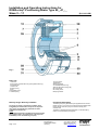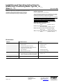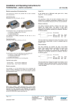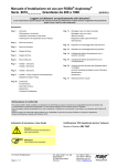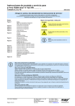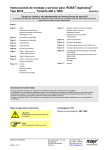
1
Installation and Operating Instructions for
ROBA-stop®-Positioning Brake Type 80_.41_._
Sizes 3 – 11
(B.1110.1.GB)
Please read and observe this Operating Instruction carefully!
A possible malfunction or failure of the brake and any damage may be caused by not observing it.
Table of contents:
Page 1:
- Table of contents
- Manufacturer’s declaration
Page 2:
- Safety regulations
Page 3:
- Safety regulations
Page 4:
- Brake view
- Parts list
- Scope of delivery
- Function description
Page 5:
- Assembly conditions
- Assembly
- Air gap adjustment
Page 6:
- Table 2 Air gap adjustment
- Braking torque adjustment
- Brake inspection
- Exchange of the wearing parts
Page 7:
- Assembly of the hand release
- Adjustment of the hand release
- Parts list hand release
Page 8:
- Electric connection
- Assembly terminal box
Page 9:
- Maintenance
- Disposal
- Breakdowns
Manufacturer’s declaration
The product is to be seen as an option or component for installation into machines or equipment according to the machinery
directive 98/37 EC. The machinery (product) must not be put into service until the machinery or equipment into which it is to be
incorporated has been declared in conformity with the provisions of the applicable EC-directives.
The product corresponds to the low voltage directives 73/23/EEC.
The observance of the relevant EMC-directive 89/336/EEC is to be guaranteed.
18/11/2004 K/KR
Page 1 of 9
Chr. Mayr GmbH + Co. KG
Eichenstraße 1
87665 Mauerstetten
Germany
Tel.: 08341 / 804-241
Fax: 08341 / 804-422
http://www.mayr.de
eMail: [email protected]
Installation and Operating Instructions for
ROBA-stop®-Positioning Brake Type 80_.41_._
Sizes 3 – 11
(B.1110.1.GB)
Safety regulations
With these safety regulations no claim on completeness is raised!
Attention!
Hazardous conditions when contacting hot
connections and components.
Notes to the electromagnetic compatibility
(EMC)
There are no emissions from the listed single
components within the meaning of the EMCdirective 89/336/EEC, however, increased
interference levels can occur when working
components are operated outside their specification
limits as for example, energising the brake in the line
side with rectifiers, phase demodulators or ROBA®switch in the line side.
Therefore, the installation and operating instructions
must be read carefully the EMC-directives are to be
observed.
Only qualified and well-trained specialists should work on
the units to avoid any personal injury or damage to
machinery.
Danger!
If the electromagnetic brake is used in an improper way.
If the electromagnetic brake has been modified or reconverted.
If the relevant standards of the safety or installation conditions
are not observed.
Attention!
The installation and operating instructions must be
read carefully and all safety regulations observed
before installation and initial operation as danger to
personnel and damage to machinery may be
caused.
The electromagnetic brakes are developed and
manufactured in conformance with the temporally
known rules of the technology and they are basically
considered as fail-safe at the time of the delivery.
Conditions of the unit
The catalogue values are reference values, which
can deviate in some cases. When selecting the
brake, site of installation, braking fluctuations,
permissible friction work, behaviour during run-in,
wear and ambient conditions are to be carefully
checked and agreed with the unit manufacturer.
Observe!
The mounting and connecting dimensions at the site of
installation must match to the size of the brake.
The brakes are designed for a relative switch on period
of 100 %.
The brakes are designed for a dry running only.
Should oil, grease, water or similar materials come in
contact with the friction surfaces the braking torque could
be reduced.
The braking torque depends on the corresponding runningin condition of the brake
The metallic surface of the brake is protected against
corrosion arranged by the factory.
Attention:
Based on the guideline 94/9/EC (ATEX-guideline) this product is
not suitable for the application in potential explosive areas
without evaluation of the conformity.
Observe!
Only qualified and well trained specialists who are familiar
with the transport, installation, initial start-up, maintenance
and operation of the units as well as with the relevant
standards may carry out the corresponding works.
Technical data and indications (Type tag and
documentation) are to be kept absolutely.
Correct supply connection according to Type tag.
Supply connections must not be released and assembly,
maintenance or repair must not be made when the unit is
energised.
Electrical leads must not be under tension when
connected.
Check current carrying components regarding damage
before installation. Current carrying components must not
be in contact with water.
Protection class I
The braking torque does not exist any more, if the friction
lining and friction surface come into contact with oil or
grease.
The protection is not only based on the basis isolation, but that
all conductive components must be connected with the
protective conductor (PE) of the fixed installation. In case the
basis isolation fails, no contact voltage can remain existing.
(VDE 0580).
Protection (electrical) IP 54:
Dust-tight and protection against contact as well protection
against splashing water from all directions.
Ambient temperature –20 °C up to +40 °C
Intended use
mayr®-brakes are determined for the use in machines and
equipment and may only be used for the ordered and confirmed
purpose.
The use beyond of the corresponding technical indications is
considered as incorrect.
18/11/2004 K/KR
Page 2 of 9
Attention!
The torque could be severely reduced in case of temperatures
over or under the freezing point due to dewing. The user must
provide corresponding counter measures.
Thermal class F (+155 °C)
The magnetic coil as well as the casting compound is designed
for a max. operating temperature of +155 °C.
Chr. Mayr GmbH + Co. KG
Eichenstraße 1
87665 Mauerstetten
Germany
Tel.: 08341 / 804-241
Fax: 08341 / 804-422
http://www.mayr.de
eMail: [email protected]
Installation and Operating Instructions for
ROBA-stop®-Positioning Brake Type 80_.41_._
Sizes 3 – 11
(B.1110.1.GB)
Safety Regulations
With these safety regulations no claim on completeness is raised!
Liability
Necessary protective measures to be
undertaken by the user:
Cover all moving parts to prevent personnel injury as squeezing
and seizing and centrifuging out.
Cover dangerously hot magnetic parts to prevent contact.
Attach a conductive connection between magnetic part and
electrical conductor (PE) of the fixed installation
(protection class I) to prevent electrical shock and inspection
conforming to standards of the unified protective connection to
all contactable metallic components. Protection against high
inductive cut-off peaks according to
VDE 0580/2000-07, par. 4.6 by fitting varistors, spark quenching
units or similar, in order to prevent damage of coil insulations or
the burn-off of the switching contact (this protection is included
in mayr®-rectifiers).
Provide additional necessary safety measures against corrosion
of the brake, if they are used in extreme ambient conditions or in
the open with direct atmospheric influences.
Measures against freezing from armature disc and rotor with
high humidity and deep temperatures.
Following directives, standards and guidelines
have been used:
98/37/EC
Machinery directive
73/23/EEC
Low-voltage directive
89/336/EEC
EMC-directive
DIN VDE 0580
Electromagnetic units and components,
general regulations
The information, notes and technical data indicated in the
documentation were at the time of printing on the latest
state.
Claims on brakes already supplied cannot be made valid
from it.
Liability for damages and breakdowns is not taken over,
with
- ignoring the installation and operating instructions,
- improper use of the brakes,
- arbitrary modification of the brakes,
- inappropriate working at the brakes,
- handling or operating errors.
Guarantee
The warranty conditions correspond to the sales and supply
conditions of Chr. Mayr GmbH + Co. KG.
Defects are to be advised immediately after detection to
mayr®.
Test mark
CE corresponding to the low voltage directive 73/23/EEC.
Marking
mayr®-components are clearly identified by means of the content
of the Type tags.
Following standards are to be observed:
EN292-1 and 2
Manufacturer
Security of machines
DIN EN61000-6-4 Interference emission
mayr®
DIN EN61000-6-2 Interference resistance
EN60204
Electrical equipment of machines
Designation/Type
Article No.
Series number
18/11/2004 K/KR
Page 3 of 9
Chr. Mayr GmbH + Co. KG
Eichenstraße 1
87665 Mauerstetten
Germany
Tel.: 08341 / 804-241
Fax: 08341 / 804-422
http://www.mayr.de
eMail: [email protected]
Installation and Operating Instructions for
ROBA-stop®-Positioning Brake Type 80_.41_._
Sizes 3 – 11
(B.1110.1.GB)
Fig. 1
Parts List
13 Fixing screw
14 Setscrew
28 Spring washer
31 Threaded distance ring
35 Rotor with friction linings (8)
58 Lock washer
59 Locking screw
60 Spring washer
1 Gear hub
2 Coil carrier complete with coil (9) and guide bushes (7)
5 Armature disc
7 Guide bush
8 Friction lining
9 Coil
10 Shoulder screw
11 Helical spring
Functional description
Delivery range / Delivery condition:
The scope of supply or the delivery condition must
immediately be checked after receipt of the shipment.
mayr® does not overtake any guarantee for faults
complained subsequently.
Claim:
Transportation damages immediately with the forwarder.
Recognizable faults / incompleteness of the shipment
immediately in the manufacturing company.
18/11/2004 K/KR
Page 4 of 9
The braking torque is generated by the applied force of several
helical springs (11) by means of a frictional locking between both
friction linings of the rotor (35), the armature disc (5) and
machine wall.
The brake is released electromechanically or mechanically by
means of a hand release (see page 6).
Chr. Mayr GmbH + Co. KG
Eichenstraße 1
87665 Mauerstetten
Germany
Tel.: 08341 / 804-241
Fax: 08341 / 804-422
http://www.mayr.de
eMail: [email protected]
Installation and Operating Instructions for
ROBA-stop®-Positioning Brake Type 80_.41_._
Sizes 3 – 11
(B.1110.1.GB)
Air gap adjustment
Assembly conditions
Before attachment of the brake, the following points must
be observed:
The eccentricity of the shaft end against the fixing hole
P.C.D. must not exceed 0,2 mm (with sizes 3 – 6), or
with larger brakes it must not exceed 0,4 mm.
The positioning tolerance of the thread for the
cap screws (13) must not exceed 0,2 mm.
The deviation in the true running of the screw-on surface to
the shaft must not exceed the permissible true running
tolerance according to DIN 42955 R.
Reference diameter is the pitch circle diameter for brake
attachment.
Larger deviations can cause a reduction in torque, a
continuous wear of the rotor and overheating.
The hub and shaft fits are to be selected to avoid any
distortion of the hub splines (observe the max. joining
temperature of 200°C). It can clamp the
rotor on the hub impairing the brake function,
(recommended hub-shaft fit H7/k6).
The hub (1) is to be brought in such position that the
toothing of the rotor (35) supports across the entire surface.
Rotors and braking surfaces must be free of oil and grease.
There has to be a suitable counter friction surface for the
rotor (35) made from steel or cast iron. Sharp-edged
interruptions of the friction surface must be avoided.
Assembly
Mount the gear hub (1) onto the shaft and lock it axially.
Avoid damaging the toothing.
The gear hub (1) is to be mounted in such a way that the
toothing of the rotor (35) remains completely engaged,
even when the friction linings (8) are worn down.
Push the rotor (35) manually onto the gear hub (1).
The rotor collar points to the brake.
Ensure that the splines slide easily.
No damage.
Attach the brake using the included fixing screws (13) and
lock it by means of the spring washers (28).
Observe the screw tightening torques according to Table 1.
Check the air gap (a1, a2), Fig. 2 nominal air gap (a1, a2)
according to Table 2 must be available. The shoulder
screws (10) Figs. 1 and 4 prevent the individual parts from
coming apart.
They do not impair the function of the brake and should not
be removed during assembly.
Fixing screws
Tightening
torques [Nm]
18/11/2004 K/KR
Page 5 of 9
As the rotor friction material (35) wears down, the air gap (a1, a2)
increases. By turning the graduated distance ring (31) the
nominal air gap can be restored. The adjustment has to be
carried out at the latest, when the maximum permissible working
air gap according to Table 2 is achieved.
Re-adjustment
1.
Remove a plug from the threaded distance ring (31).
Measure the air gap in a de-energised condition with a
feeler gauge before an adjustment. The difference between
the measured air gap and nominal air gap (a1, a2)
according to Table 2 must be re-adjusted.
2. Loosen the fixing screws (13).
3. Release the locking screw (59) and lock washer (58).
4. Turn the threaded distance ring (31) counter-clockwise
(when looking at brake back side). Turning the distance
ring (31) by one graduation of the stamped scale
corresponds to an air gap adjustment for the sizes 3 to 6 of
0,05 mm, for the sizes 7 to 11 of 0,1 mm.
5. Tighten the fixing screws (13), observe the tightening
torques according to Table 1.
6. Tighten the clamping screw (59).
7. Check the air gap; nominal air gap (a1, a2), according to
Table 2 must be available.
This adjustment can be repeated so often, until the graduated
distance ring (31) contacts the rod-stop of the coil carrier (2),
Fig. 2. This contact avoids an unacceptable wear of the rotor
(35). If a re-adjustment is not possible any more, the rotor (35)
must be exchanged. You can find data on the rotor thickness in
a new condition and thickness after a max. wear in Table 2.
Collar
Type 802.41_. _
Fast acting
armature
Table1
ROBA-stop®
Size
The working air gap between armature disc (5) and
coil carrier (2) is adjusted to the nominal dimension (a1, a2) in
the factory, Fig. 2 and Table 2
The size of the nominal air gap depends on the structural form
of the armature disc (5). The third figure of the Type number
informs on the fitted armature disc.
3
4
5
6
7
8
9
10
Naps
Type 800.41_. _
Standard armature
11
Fig. 2
3x 3x 3x 3x 3x 3x 6x 6x 6x
M4 M4 M5 M6 M6 M8 M8 M8 M12
3
3
6
8
8
10
10
10
40
Chr. Mayr GmbH + Co. KG
Eichenstraße 1
87665 Mauerstetten
Germany
Tel.: 08341 / 804-241
Fax: 08341 / 804-422
http://www.mayr.de
eMail: [email protected]
Type 804.41_. _
Fast acting silencing
armature
Installation and Operating Instructions for
ROBA-stop®-Positioning Brake Type 80_.41_._
Sizes 3 – 11
(B.1110.1.GB)
Table 2
ROBA-stop®
Size
3
4
5
6
7
8
9
10
11
Nominal air gap Type 80_ "a1"
[mm]
0,20
0,20
0,25
0,25
0,35
0,35
0,40
0,40
0,50
Nominal air gap Type 804 "a2"
[mm]
0,35
0,35
0,40
0,45
0,60
0,60
0,65
0,70
0,80
Dimension b (Fig. 2)
[mm]
4,25
4,50
4,50
6,25
0,75
0,70
0,85
0,75
0,90
0,80
1,0
0,85
1,0
0,85
no naps
3 naps at the outer-Ø, therefore measuring only in this
range
Max, air gap *
(with nominal torque)
[mm]
Type 800
Type 802
0,40
0,35
0,45
0,40
no naps
1,1
0,90
1,6
1,4
Rotor thickness in a new condition
[mm]
5
6
7
8,5
11
12,5
15
17
24
Rotor thickness after complete wear
[mm]
3,5
4,35
5,2
6,55
8,9
10,2
12
13,4
20,1
* The max. working air gap can be reduced with increasing working temperature.
Braking torque adjustment
ROBA-stop®-brakes are adjusted to the braking torque
requested in the order in the factory. The braking torque is
reduced by turning the set screws (14) counter-clockwise and
increased by turning them clockwise.
All set screws (14) must be uniformly adjusted, when the braking
torque is adjusted.
Attention!
Do not interchange set screws (14) with fixing
screws (13) by mistake!
In case the braking torque shall be essentially reduced, the
helical springs (11) must be removed. Always two springs lying
opposite should be taken out so that the armature (6) is
uniformly loaded.
Friction lining side
Type 802.41_. _
Fast acting armature
Brake inspection
The full adjusted braking torque is only achieved after the run-in
process has been carried out.
The braking torque (switching torque) is the slipping torque
acting on the shafting at a running speed of 1 m/s referred to the
mean friction radius (acc. to DIN VDE 0580/10.94).
Table 3
ROBA-stop®
Size
Set screws
3
4
5
6
7
8
9
10
11
Type 800.41_. _
Standard armature
6 x 6 x 6 x 6 x 12 x 12 x 12 x 12 x 16 x
M 5 M 6 M10 M10 M10 M14 M8 M10 M12
Number of
brake springs
6
6
6
6
12
12
12
12
16
Exchange of the wearing parts
The rotor (35), armature disc (5) and gear hub (1) are wearing
parts. Unscrew the brake (remove the fixing screws (13)),
exchange the rotor (35). If there is extreme clearance in the
toothing between rotor (35) and gear hub (1), pull off the gear
hub (1) from the shaft and replace it. Furthermore check the
armature disc (5) as to plane parallelity and check the wear and
exchange it, if necessary.
Restore the nominal air gap via the distance ring (31).
The shoulder screws (10) as well as the hand release (if
available) must be removed for exchanging the armature
disc (5). Pay attention that the helical springs (11) do not fall out.
The armature disc (5) can be different depending on the brake
Type.
Therefore, observe the mounting position, Fig. 3.
18/11/2004 K/KR
Page 6 of 9
Magnetic elem. side
Type 804.41_. _
Fast acting
silencing armature
Fig. 3
Chr. Mayr GmbH + Co. KG
Eichenstraße 1
87665 Mauerstetten
Germany
Tel.: 08341 / 804-241
Fax: 08341 / 804-422
http://www.mayr.de
eMail: [email protected]
Installation and Operating Instructions for
ROBA-stop®-Positioning Brake Type 80_.41_._
Sizes 3 – 11
(B.1110.1.GB)
1)
Assembly of the Hand release
The hand release can be mounted to each Type of the
positioning brake, with the exception of the Type 804.41_. _
(Brake with fast acting silencing armature disc).
The brake must be dismantled and de-energised for the
assembly.
Push the return spring (19) onto the restoring bolt (17).
Take out the plastic plugs from the bores on the back side
of the coil carrier (2).
Push the restoring bolt (17) through the recesses in the
armature disc (5) and through the bores in the
coil carrier (2).
Bolt the hand release bracket (22) with the locking nuts (21)
onto the restoring bolt (17).
Fig. 5
Fitting the hand release
The restoring bolts (17) limit the stroke of the armature disc (5)
in brake direction, Figs. 4 and 5.
Attention:
The restoring bolts (17) may only be tightened by
the locking nuts (21) so that the adjusting
dimension “X” according to Table 4 and Fig. 5 remains existing
at least between armature disc (5) and coil carrier (2).
Table 4
ROBA-stop®
Size
3
4
5
6
7
8
9
Adjusting dim. "X" [mm] 1,0 1,1 1,2 1,6 1,4 1,5 1,5
1) Please contact the factory regarding the hand release sizes 10 and 11.
Parts List hand release
10 Shoulder screw
16 Threaded bolt
17 Restoring bolt
18 Ball button
19 Return spring
21 Lock nut
22 Hand release bracket
Inspection
hole
Fig. 4
18/11/2004 K/KR
Page 7 of 9
Chr. Mayr GmbH + Co. KG
Eichenstraße 1
87665 Mauerstetten
Germany
Tel.: 08341 / 804-241
Fax: 08341 / 804-422
http://www.mayr.de
eMail: [email protected]
Installation and Operating Instructions for
ROBA-stop®-Positioning Brake Type 80_.41_._
Sizes 3 – 11
Electric connection
Warning!
Electrical connection only in a voltage free
condition.
The coil voltage is indicated on the Type tag,
additionally it is stamped on the brake.
The brakes are designed according to Euro-voltage DIN IEC 38.
DC current is necessary for the operation.
DC or AC current switchings are possible.
DC current switching, however, gains a faster engaging time
(engagement of the brake).
In case a faster disconnection time of the brake is desired, a
special ROBA®-switch fast acting rectifier is necessary.
In this case please contact our company.
Attention!
Cut-off peaks may arise during switching-off of electromagnetic
units. These can cause damage to the units and are, therefore,
to be damped.
The connection times indicated in the catalogue can be
deteriorated by this damping.
A protection of the voltage supply according to the current
values is to be provided.
The brakes are designed for a relative duty cycle of 100 %.
(B.1110.1.GB)
The components 37 to 43 of the parts list are pre-assembled.
1. a) Screw rectifier into the terminal box - lower part (39) or
1. b) screw panel (44) into the terminal box – lower part (39)
with the countersunk screws (45). Mount the terminals with
2-, 4- or 6-poles (46) with caps screws onto the panel (44).
Glue the terminal marking (47) onto the panel (44).
(Observe the position of the terminal marking
acc. to Fig. 5).
2. Cut the cable of the brake coil to the suitable length and strip
it. Lead the cable into the terminal box through the
components 39, 40 and 41.
3. Screw the holding bracket (37) with cap screws (49) to the
brake back side.
4. Pull the brake coil, tighten the hexagon nuts (42).
5. Connect the brake acc. to the installation and operating
instructions No. B.1110.4.GB for ROBA-stop®-brakes /
electric connection“.
6. Close the terminal box. Observe the sealing (51) and
sealing washers (53).
Assembly terminal box
Panel (44) mounted by choice with:
1. Terminal 2-poles
2. Terminal 4-poles
3. Terminal 6-poles
4. Half-wave rectifier
5. Bridge rectifier
Fig. 6
Parts list terminal box
37 Holding bracket
38 Cap screw M3 x 12
39 Terminal box – lower part
40 O-ring
41 Sealing plate
42 Hexagon nut M3
43 Cable gland
44 Panel
45 Countersunk screw M4 x 8
46 Terminal
47 Terminal marking
48 Cap screw M2,5 x 12
49 Cap screw M4 x 8
50 Terminal box cover
51 Sealing ring
52 Cap screw M4 x 30
53 Sealing washer
Panel (44)
mounted by choice with
1. Terminal 2-poles
2. Terminal 4-poles
3. Terminal 6-poles
4. Half-wave rectifier
5. Bridge rectifier
Cable of the brake coil
Fig. 7
Maintenance
Attachment
18/11/2004 K/KR
Page 8 of 9
ROBA-stop®-brakes are virtually maintenance free.
The friction linings are robust and wear resistant ensuring a very
Chr. Mayr GmbH + Co. KG
Tel.: 08341 / 804-241
Eichenstraße 1
Fax: 08341 / 804-422
87665 Mauerstetten
http://www.mayr.de
Germany
eMail: [email protected]
Installation and Operating Instructions for
ROBA-stop®-Positioning Brake Type 80_.41_._
Sizes 3 – 11
long brake service life.
However, the gear hub (1), armature disc (5) as well as the rotor
with friction linings (35) are subject to wear and must be
checked at regular intervals and exchanged, if necessary.
See for this the chapter "Exchange of the wearing parts”.
(B.1110.1.GB)
Disposal
Electronic components
(rectifier / ROBA®-switch / micro switch):
The not disassembled products can be supplied to the material
utilization according to EAK 150106 (mixed material) or via the
household waste (code No. 200301) to the disposal.
The components of our Electromagnetic Brakes must separately
be supplied to the utilisation due to the different material
components. Additionally the legal instructions are to be
observed. Code numbers can change with the kind of the
separation (metal, plastic and cable).
Brake body made of steel with coil/cable
and all other steel components:
Scrap
(Code No. 160117)
Distance ring made of aluminium:
Non-ferrous metal (Code No. 160118)
Brake rotor (steel or aluminium with friction lining):
Brake linings
(Code No. 160112)
Seals, O-rings, V-Seal, Elastomere, Terminal boxes (PVC):
Plastic
(Code No. 160119)
Breakdowns:
Failures
Possible reasons
Solution
Brake does not release
False voltage measured at the rectifier
Apply correct voltage
Rectifier failed
Exchange rectifier
Air gap too big (rotor worn down)
Replace rotor
Air gap too big (metallic particles between
armature disc and coil carrier)
Clean the brake
Coil interrupted
Exchange the brake
Brake becomes too warm
Use fast acting rectifier
Hand release is adjusted falsely
Adjust the distance correctly
Hand release play; (possible with decreased
torque or operation with fast acting rectifier)
Replace rotor
Brake is switched to AC side
Switch to DC side
Motor does not brake
Brake engages with delay
18/11/2004 K/KR
Page 9 of 9
Chr. Mayr GmbH + Co. KG
Eichenstraße 1
87665 Mauerstetten
Germany
Tel.: 08341 / 804-241
Fax: 08341 / 804-422
http://www.mayr.de
eMail: [email protected]