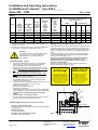
1
Installation and Operating Instructions for ROBA-stop®-silenzio® Type 896.2_ _._ _ Sizes 300 – 1800 (B.8.7.1.GB) Please read and observe this Operating Instruction carefully! A possible malfunction or failure of the clutch and damage may be caused by not observing it. Table of contents: Page 8: - Noise damping - Electrical connection of the brake - Engagement of the brake - Switch-off of the brake - Fuse protection of the unit - Switching example Page 1: - Table of contents - Manufacturer’s declaration Page 2: - Safety regulations Page 3: - Safety regulations - TÜV- approvals Page 4: - Brake views - Safety and information signs Page 9: - Release monitoring - Wiring diagram release monitoring - Function of the release monitoring - Table 3: Maximum and minimum switch capacity - Assembly and adjustment of the release monitoring - Switch adjustment - Monitoring of the release monitoring after attachment on the customer side Page 5: - Parts list - Technical data - Table 1: Technical data (size dependently) Page 6: - Friction power diagram - Delivery range / delivery condition - Application - Function description - Assembly conditions Page 10: - Maintenance - Disposal - Breakdowns Page 7: - Table 2: Braking torques, air gaps, spanner gaps and tightening torques - Assembly - Brake inspection - Emergency hand release Manufacturer’s declaration The product is to be seen as an option or component for installation into machines or equipment according to the machinery directive 98/37 EC. The machinery (product) must not be put into service until the machinery into which it is to be incorporated has been declared in conformity with the provisions of the applicable EC-directives. The product corresponds to the low voltage directives 2006/95/EC. The product corresponds to the elevator guideline 95/16/EC. The observance of the relevant EMV-guideline 89/336/EEC is to be guaranteed. 06/09/2007/TK/HW/KR Page 1 of 10 Chr. Mayr GmbH + Co. KG Eichenstraße 1 D-87665 Mauerstetten Germany Tel.: 08341 / 804-241 Fax: 08341 / 804-422 http://www.mayr.de eMail: [email protected] Installation and Operating Instructions for ROBA-stop®-silenzio® Type 896.2_ _._ _ Sizes 300 – 1800 (B.8.7.1.GB) Safety Regulations With this safety regulations no claim on completeness is raised! Notes to the electromagnetic compatibility (EMV) Attention! Hazardous conditions when contacting hot connections and components. There are no emissions from the listed single components within the meaning of the EMVguideline 89/336/EEC, however, increased interference levels can occur when working components are operated outside their specification limits as for example, energising the brake with rectifiers, phase demodulators or ROBA®-switch in the line side. Therefore, the installation and operating instructions must be read carefully the EMV-guidelines are to be observed. Only qualified and well-trained specialists should work on the units to avoid any personal injury or damage to machinery. Danger! If the electromagnetic brake is used in an improper way. If the electromagnetic brake has been modified or reconverted. If the relevant standards of the safety or installation conditions are not observed. Attention! The installation and operating instructions must be read carefully and all safety regulations observed before installation and initial operation as danger to personnel and damage to machinery may be caused. The electromagnetic brakes are developed and manufactured in conformance with the temporally known rules of the technology and they are basically considered as fail-safe at the time of the delivery. Attention: Conditions of the unit The catalogue values are reference values, which can deviate in some cases. When selecting the brake, site of installation, braking fluctuations, permissible friction work, behaviour during run-in, wear and ambient conditions are to be carefully checked and agreed with the unit manufacturer. Observe! The mounting and connecting dimensions at the site of installation must match to the size of the brake. The brakes are designed for a relative switch on period of 100 %. Based on the guideline 94/9/EC (ATEX-guideline) this product is not suitable for the application in potential explosive areas without evaluation of the conformity. The brakes are designed for a dry running only. Should oil, grease, water or similar materials come in contact with the friction surfaces the braking torque could be reduced. Observe! The braking torque depends on the corresponding runningin condition of the brake. Only qualified and well trained specialists who are familiar with the transport, installation, initial start-up, maintenance and operation of the units as well as with the relevant standards may carry out the corresponding works. The metallic surface of the brake is protected against corrosion arranged by the factory. Protection class I Technical data and indications (Type tag and documentation) are to be kept absolutely. Correct supply connection according to Type tag. Supply connections must not be released and assembly, maintenance or repair must not be made when the unit is energized. Electrical leads must not be under tension when connected. Check current carrying components regarding damage before installation. Current carrying components must not be in contact with water. The braking torque does not exist any more, if the friction lining and friction surface come into contact with oil or grease. The protection is not only based on the basis isolation, but that all conductive components must be connected with the protective conductor (PE) of the fixed installation. In case the basis isolation fails, no contact voltage can remain existing. (VDE 0580). Protection (mechanical) IP 20: Protection against fingers or similar large objects, against medium-sized foreign bodies > 12 mm diameter. No water protection. Protection (electrical) IP 54: Intended use Dust-tight and protection against contact as well protection against splashing water from all directions. mayr®-brakes are determined for the use in machines and equipment and may only be used for the ordered and confirmed purpose. Ambient temperature –20 °C up to +40 °C The use beyond of the corresponding technical indications is considered as incorrect. The torque could be severely reduced in case of temperatures over or under the freezing point due to dewing. The user must provide corresponding counter measures. Attention! Thermal class F (+155 °C) The magnetic coil as well as the casting compound is designed for a max. operating temperature of +155 °C. 06/09/2007/TK/HW/KR Page 2 of 10 Chr. Mayr GmbH + Co. KG Eichenstraße 1 D-87665 Mauerstetten Germany Tel.: 08341 / 804-241 Fax: 08341 / 804-422 http://www.mayr.de eMail: [email protected] Installation and Operating Instructions for ROBA-stop®-silenzio® Type 896.2_ _._ _ Sizes 300 – 1800 (B.8.7.1.GB) Safety Regulations With this safety regulations no claim on completeness is raised! Necessary protective measures to be undertaken by the user: Liability Cover all moving parts to prevent personnel injury as squeezing and seizing and centrifuging out. Cover dangerously hot magnetic parts to prevent contact. Attach a conductive connection between magnetic part and electrical conductor (PE) of the fixed installation (protection class I) to prevent electrical shock and inspection conforming to standards of the unified protective connection to all contactable metallic components. Protection against high inductive cut-off peaks according to VDE 0580/2000-07, par. 4.6 by fitting varistors, spark quenching units or similar, in order to prevent damage of coil insulations or the burn-off of the switching contact (this protection is included in mayr®-rectifiers). Provide additional necessary safety measures against corrosion of the brake, if they are used in extreme ambient conditions or in the open with direct atmospheric influences. Measures against freezing from armature disc and rotor with high humidity and deep temperatures. Following directives, standards and guidelines have been used: 98/37/EC Machinery directive 2006/95/EC Low-voltage directive 89/336/EEC EMV-guideline 95/16/EC Elevator guidelines EN 81-1 Safety regulations for the design and Installation of elevators and small goods elevators DIN VDE 0580 Electromagnetic units and components, general regulations The information, notes and technical data indicated in the documentation were at the time of printing on the latest state. Claims on brakes already supplied cannot be made valid from it. Liability for damages and breakdowns is not taken over, with - ignoring the installation and operating instructions, - improper use of the brakes, - arbitrary modification of the brakes, - inappropriate working at the brakes, - handling or operating errors. Guarantee The warranty conditions correspond to the sales and supply conditions of Chr. Mayr GmbH + Co. KG. Defects are to be advised immediately after detection to mayr®. Test mark CE corresponding to the low voltage directive 2006/95/EC. Marking mayr®-components are clearly identified by means of the content of the Type tags. Manufacturer mayr® Following standards are to be observed: DIN EN ISO 12100-1 and 2 Designation/Type Security of machines DIN EN61000-6-4 Interference emission EN12016 Interference resistance (for elevators, escalators and moving sidewalks) EN60204 Electrical equipment of machines Article No. Series number TÜV-Approvals: The sizes 300 to 1800 shown here with a microswitch for release monitoring have been prototype-inspected by the South German TÜV as brake systems having an effect on the drive sheave shaft and as part of a protective system for the upwards-moving elevator cage against excessive speed. These brakes are single-circuit brakes. An operational brake (dual circuit brake) is not required in elevators. Approval number: ABV 762/1 06/09/2007/TK/HW/KR Page 3 of 10 Chr. Mayr GmbH + Co. KG Eichenstraße 1 D-87665 Mauerstetten Germany Tel.: 08341 / 804-241 Fax: 08341 / 804-422 http://www.mayr.de eMail: [email protected] Installation and Operating Instructions for ROBA-stop®-silenzio® Type 896.2_ _._ _ Sizes 300 – 1800 (B.8.7.1.GB) 15 5.3 9 10 8 6 2 11 1 3 4 4.1 14 12 Cable length approx. 1000 mm Nom. air gap "a" +0,15 -0,1 Fig. 1 Single air gaps "b" Fig. 2 Fig. 3 7.4/7.5 "b" 7.3 7.1 7.2 6.1 6 Fig. 4 7.3 Fig. 5 7.1 Safety and information signs 5.1 Attention! Risk of injury for persons and damage at the machine possible. 5.2 Dim. 4 ±0,5 Note! Reference to important points which are to be considered. with a de-energized brake Fig. 6 06/09/2007/TK/HW/KR Page 4 of 10 Chr. Mayr GmbH + Co. KG Eichenstraße 1 D-87665 Mauerstetten Germany Tel.: 08341 / 804-241 Fax: 08341 / 804-422 http://www.mayr.de eMail: [email protected] 16 Installation and Operating Instructions for ROBA-stop®-silenzio® Type 896.2_ _._ _ Sizes 300 – 1800 Parts List (B.8.7.1.GB) (Only mayr original parts are to be used) 1 Hub 6 2 Coil carrier (assembly) 6.1 Thrust spring 3 Armature disc 7. 4 Rotor 1 7.1 Micro switch 11 Flange plate 4.1 Rotor 2 7.2 Cap screw 12 Cap screw 5 Emergency hand release (assembly) Intermediate washer 8 Hexagon head cap screw 9 Washer Release monitoring (assembly) 10 Distance bolts 7.3 Hexagon head cap screw 13 Noise damping 5.1 Stud bolt 7.4 Hexagon nut 14 Thrust spring 5.2 Hexagon nut 7.5 Spring washer 15 Cover 5.3 Safety information label 7.6 Cap screw 16 Type tag German and English 7.7 Cable clip Technical data Nominal voltages: 24 V/104 V/180 V/207 V Protection (electrical) IP54 Protection (mechanical) IP10 Duty cycle: 100 % Connection: 2 x 0,88 mm² Ambient temperature: -20 °C up to +40 °C Table 1: Technical data (size-dependently) Braking torque (tolerance +60 %) [Nm] Nominal Increased Reduced Electric Maximum torque torque torque rated power speed 100 % 120 % 75 % Type Type Type Size 896.20_._ _ 896.21_._ _ 896.22_._ _ [rpm] [W] 300 500 800 1300 1800 600 1000 1600 2600 3600 700 1200 2000 3120 4300 450 760 1200 1960 2700 300 300 300 250 250 86 90 107 130 150 Mass* [kg] 40,5 53 80 113 153 Number of the thrust springs Switching times with (Pos. 6.1) nom. braking torque 100 % in the intermediate washer (Pos. 6) Pick up Drop t1 (AC) Drop t1 (DC) t2 [ms] [ms] [ms] 2 3 6 8 4 308 444 581 589 850 * Mass incl. flange plate with screws 06/09/2007/TK/HW/KR Page 5 of 10 Chr. Mayr GmbH + Co. KG Eichenstraße 1 D-87665 Mauerstetten Germany Tel.: 08341 / 804-241 Fax: 08341 / 804-422 http://www.mayr.de eMail: [email protected] 1087 1023 1231 1464 1920 246 193 267 266 420 Installation and Operating Instructions for ROBA-stop®-silenzio® Type 896.2_ _._ _ Sizes 300 – 1800 Friction power diagram with n = 300 rpm for sizes 300 up to 800 with n = 250 rpm for sizes 1300 up to 1800 Functional description The ROBA-stop®-silenzio® Type 896.2_ _._ is designed a dual disc brake. The braking torque is generated by the applied force of several thrust springs (14) by means of a frictional locking between the friction linings of the rotors (4 and 4.1), the armature disc (3), the intermediate washer (6) and the flange plate (11) or machine wall. The brake is electromechanically released. For the functional test (TÜV-inspection) of an additional dual circuit brake or for an emergency-evacuation, the torque of this brake can be set mechanically to 0 with the emergency hand release (5) for the duration of the functional test or for the duration of the emergency-evacuation. Alternatively this can also be achieved by energising the magnetic coil. See also item emergency hand release => observe warning information! 1800 Permitted friction work [J] 1300 500 (B.8.7.1.GB) 800 300 Assembly conditions The eccentricity of the shaft end relative to the fixing hole P.C.D. must not exceed 0,2 mm. The positioning tolerance of the threads for the hexagon head cap screws (8 ) must not exceed 0,2 mm. The deviation in the true running of the screw-on surface to the shaft must not exceed the permissible true running tolerance acc. to DIN 42955 R of 0,05 mm with size 300, and 0,063 mm with sizes 500 up to 1800. Reference diameter is the pitch circle diameter for brake attachment. Larger deviations can cause a drop of the torque, continuous wear of the rotor and overheating. Brake pre-assembled. Supplied loose: Flange plate (11 / type dependent option) with cap screws (12), hexagon head cap screws (8) with washers (9), cover (15), hub (1) , thrust springs (6.1) and rotor 1 (4). The scope of supply or the delivery condition must immediately be checked after receipt of the shipment. mayr® does not overtake any guarantee for faults complained subsequently. Transportation damages must immediately be advised to the forwarder. Recognizable faults / incompleteness of the shipment must immediately be advised to the manufacturing company. The hub (1) and shaft fits are to be selected to avoid any distortion of the hub splines (1). It can clamp the rotors (4 and 4.1) on the hub (1) impairing the brake function, (recommended hub-shaft fit H7/k6). The max. joining temperature of 200 °C must not be exceeded. Switching frequency [1/h] Delivery range / Delivery condition Application As a holding brake with emergency-stop Attachment to slowly running machine shaft, for example gearbox output shaft. In enclosed buildings (in tropical area, with high air humidity with long downtimes and sea climate only with special measurements). In a dry running environment. Horizontal and vertical mounting positions. In a clean environment (coarse dust as well as liquids of all kinds impair the brake function, ⇒ fit a cover). 06/09/2007/TK/HW/KR Page 6 of 10 When the brake has been supplied without flange plate (11), a geometry of the screw-on surface, as described in the catalogue P.896.V__.GB, is to be provided (corresponding diameter and contact for cover). Rotors (4 and 4.1) and braking surfaces must be free of oil and grease. There has to be a suitable counter friction face (steel or cast iron). Sharp-edged interruptions of the friction face must be avoided. Recommended surface quality of the friction surface Ra = 1,6 µm. Especially mounting areas made of cast iron arranged by the customer are additionally to be drawn off with a fine abrasive paper (granulation ≈ 400). Chr. Mayr GmbH + Co. KG Eichenstraße 1 D-87665 Mauerstetten Germany Tel.: 08341 / 804-241 Fax: 08341 / 804-422 http://www.mayr.de eMail: [email protected] Installation and Operating Instructions for ROBA-stop®-silenzio® Type 896.2_ _._ _ Sizes 300 – 1800 (B.8.7.1.GB) Table 2 Size 300 500 800 1300 1800 Rotor thickness new condition - 0,05 [mm] Nominal air gap "a" de-energized + 0,15 / - 0,1 [mm] 13,9 16 18 18 18 0,60 0,60 0,65 0,70 0,70 Fixing screws with spanner gaps and tightening torques [mm] Maximum air gap * "amax." with nominal torque 100 % [mm] Maximumair gap * "amax." with torque 75 % or 120 % ** [mm] Pos. 8 SW [Nm] Pos. 12 SW [Nm] 0,15 0,15 0,18 0,20 0,20 1,0 1,0 1,0 1,1 1,1 1,3 1,3 1,3 1,5 1,5 3 x M12 6 x M12 6 x M16 8 x M16 8 x M16 18 18 24 24 24 123 123 250 250 300 6 x M12 6 x M16 6 x M16 8 x M16 8 x M20 10 14 14 14 17 123 200 300 300 470 Single air gaps "b" released min. Brake Flange plate (11) * The rotors must be exchanged when the maximum air gap is ** achieved. However the brake is already getting louder with an air gap > "a" +0,2 mm. In case of an increased torque (120 %) it must be released with overexcitation (if necessary contact company mayr ®). Attention! The braking function is not guaranteed any more with air gap > max. air gap for brakes with a reduced braking torque or operation with overexcitation. Assembly (Figs. 1 to 6) 1. 2. 3. 4. 5. 6. If necessary, assemble flange plate (11 / type dependent option) using cap screws (12) at the mounting surface (observe tightening torque according to Table 2). Assemble hub (1) onto the shaft and bring it to the correct position (supporting length of the keyway over the complete hub and lock it axially (e.g. with a locking ring). Push rotor 1 (4) manually onto the gear hub (1) (rotor collar pointing away from the machine wall or flange plate). Ensure that the splines slide easily. Screw the thrust springs (6.1) into the step bores of the intermediate washer (6) in a counter-clockwise direction (number of pieces see Table 1). Push brake body with intermediate washer (6) and rotor 2 (4.1) over hub (1) and rotor collar from the rotor 1 (4). Carefully joint the splines. Ensure that the splines slide easily. No damage to the splines. Insert the hexagon cap head screws (8) uniformly distributed into the brake body and uniformly tighten them all around with a torque wrench and tightening torque (according to Table 2). Check air gaps "a" according to Table 2. A nominal air gap "a" with de-energised brake and the single air gaps "b" with released brake must be given. Emergency hand release (Pos. 5 / Fig. 6) The brakes have an emergency hand release (5) to be able to drive the lift cage up or down in case of an emergency-evacuation with the aid of an additional dual circuit brake, or to set the torque of this brake to 0 in case of a TÜV-inspection of the additional dual circuit brake. For this, both hexagon nuts (5.2) must be uniformly tightened so long until the armature disc (3) contacts the coil carrier (2) against the force of the thrust springs (14). In case of a restart of the elevator or equipment the distance between both hexagon nuts (5.2) and coil carrier (2), as described on Fig. 6, must absolutely be reset to 4 ±0,5 mm (with a de-energised brake). Observe both yellow warning instruction labels in German and English near by both hexagon nuts (5.2). Nothandlüftung Achtung! Attention! Bis Anlage am Spulenträger aufgeschraubte Notlüftmuttern heben das Bremsmoment auf. Die Benutzung darf nur durch autorisiertes Fachpersonalerfolgen. Die Muttern müssen nach erfolgter Not-Evakuierung oder TÜV-Prüfung wieder auf Abstand 4 mm zurückgeschraubt werden. Hand release nuts screwed on contact to coil carrier eleminate the brake torque. Operation is allowed only by authorised and qualified personnel. After evacuation or TÜV-inspection the nuts must be turned back to a distance of 4 mm to the coil carrier 3 2 5.1 5.2 Brake inspection (Before initial start of the brake) Dim. 4 ±0,5 - Inspection of the braking torque: compare ordered braking torque with the braking torque indicated on the type tag. - Release inspection: by energising the brake. - Inspection of the hand release function: see page 9 (Type dependently). 06/09/2007/TK/HW/KR Page 7 of 10 with a de-energized brake Fig. 7 Chr. Mayr GmbH + Co. KG Eichenstraße 1 D-87665 Mauerstetten Germany Tel.: 08341 / 804-241 Fax: 08341 / 804-422 http://www.mayr.de eMail: [email protected] Installation and Operating Instructions for ROBA-stop®-silenzio® Type 896.2_ _._ _ Sizes 300 – 1800 (B.8.7.1.GB) Noise damping Switching-OFF On the AC current side with the switch S3 and a bridge via the terminals 3 and 4. Important note: An exchange of the damping elements is only permissible at the factory mayr®. Observe! The noise damping is factory set. The noise damping is subject Application for standard operation to a certain aging depending, however, on the application or Silent switching, but longer engaging time of the brake operational condition (torque adjustment, switching frequency, (approx. 6-8 times longer than with switching-OFF on the DC ambient conditions, natural vibration of the operational current side). equipment etc.). Switching-OFF On the DC current side with the switches S1 and S2 Electrical connection The coil voltage is indicated on the Type tag. Additionally it is stamped on the coil carriers (2). The brakes are designed acc. to Euro-voltage DIN IEC 60038. DC current is necessary for the operation. It can be generated via transformer-rectifiers or bridge connected rectifiers. DC or AC current switchings are possible. DC current switching, however, gains a faster engaging time (engagement of the brake). Attention! Cut-off peaks may arise during switching-off of electromagnetic units. These can cause damage to the units and are, therefore, to be damped. The connection times indicated in the catalogue can be deteriorated by this damping. A protection of the voltage supply according to the current values is to be provided. The brakes are designed for a relative duty cycle of 100 %. Observe! Noisy switching but short engaging time of the brake Application for emergency-OFF-operation! Important! In case of switching-OFF on the DC side the coil must be protected against transient overvoltages by means of a suitable protective wiring according to VDE 0580 (included in mayr®-rectifiers). Miniature fuse F1 A miniature fuse for protection against short circuits must be provided in the supply mains by the customer. Switching example (Fig. 8) Note! We recommend to use the bridge connected rectifier shown on Fig. 8 (noise reduction). Wiring should be made with a series-connected fuse F1. Switching-ON Switching-ON is either only made on the AC current side with the switch S3 and a bridge via the terminals 3 and 4. (in this case there are no switches S1 and S2), or on the AC and DC sides with the switches S1 and S2 (in this case there is no switch S3). Bridge connected rectifier: - 1 U~ 2 + 3 4 5 U– 6 fuse F1 S1 S2 coil - brake S3 AC S1 and S2 S3 F1 AC DC switching AC switching external fuse mains connection Fig. 8 06/09/2007/TK/HW/KR Page 8 of 10 Chr. Mayr GmbH + Co. KG Eichenstraße 1 D-87665 Mauerstetten Germany Tel.: 08341 / 804-241 Fax: 08341 / 804-422 http://www.mayr.de eMail: [email protected] Installation and Operating Instructions for ROBA-stop®-silenzio® Type 896.2_ _._ _ Sizes 300 – 1800 Assembly and adjustment (at the factory Fig. 9) Release monitoring (7) Fig. 9 (type dependently option) The ROBA-stop®-silenzio® brakes are supplied with factory set release monitoring units. A micro switch each (pos. 7.1) per brake circuit gives signal for every change of the brake condition: "brake released" or "brake closed" An evaluation of the signal of both conditions must be made by the customer. From the time when the brake is energised a period of three times the separation time must be passed, before the micro switch signal of the release monitoring system is evaluated. Wiring diagram of each micro switch (7.1): 2 break contact connection grey continuity when brake closed 1 input connection black 4 make contact connection blue continuity when brake released Function. When the magnetic coil is energised in the coil carrier (2) the armature disc (3) is attracted to the coil carrier (2), a micro switch (7.1) gives signal, the brake is released. Table 3: Maximum switch capacity AC switch capacity Resistance Voltage load [VAC] [A/R load] 125 5 250 5 DC switch capacity Resistance Voltage load [VDC] [A/R load] up to 30 5 125 0,5 250 0,25 7.3 7.1 7.2 Attention! Brake bolted at the assembly device with a tightening torque according to Table 2 and coil deenergized. 1. Joint the hexagon head cap screw (7.3) with hexagon nut (7.4) and spring washer (7.5), put LOCTITE 243 at the beginning of the thread and screw them into the armature disc (4). 2. Screw the micro switch (7.1) with cap screws (7.2) to the preassembled brake body (secure it with LOCTITE 243). Adjustment of the switch 3. Turn hexagon head cap screw (7.3) towards the switch (7.1) until contact of the micro switch ram. 4. Connect test or measuring devices (diode inspection) at the make contact black/blue. 5. Joint feeler gauge 0,2 mm (loose feeler sheet) between switch ram (7.1) and hexagon-head screw (7.3). 6. Turn hexagon head cap screw (7.3) towards the switch (7.1) until signal "ON", return it until signal "OFF", lock hexagon head cap screw (7.3) with hexagon nut (7.4). 7. Energise brake signal "ON". De-energise brake signal "OFF". If necessary, re-adjust it and repeat inspection. (clock 3 up to 5 times). 8. Inspection with feeler gauge 0,25 mm Brake energised signal "ON", Brake de-energised signal "ON" 9. Inspection with feeler gauge 0,20 mm Brake energised signal "ON", Brake de-energised signal "OFF" 10. Joint feeler gauge 0,3 mm between armature disc (4) and coil carrier (3) in the range of the switches (7.1), energise brake, signal must be "ON". 11. Provide positions 7.4 and 7.2 with securing lacquer. Inspection after attachment Minimum switch capacity: 0,12VA ( > 12V, > 10mA) Contact material: silver 7.4/7.5 (B.8.7.1.GB) The connection at the customer is made as make contact. The release monitoring are to be checked: brake de-energised Signal "OFF", brake energised Signal "ON" Micro switches are not considered as fail safe, an appropriate access for the exchange or adjustment must be possible. 2 3 4 6 4.1 Fig. 9 06/09/2007/TK/HW/KR Page 9 of 10 Chr. Mayr GmbH + Co. KG Eichenstraße 1 D-87665 Mauerstetten Germany Tel.: 08341 / 804-241 Fax: 08341 / 804-422 http://www.mayr.de eMail: [email protected] Installation and Operating Instructions for ROBA-stop®-silenzio® Type 896.2_ _._ _ Sizes 300 – 1800 Maintenance Disposal ROBA-stop®-silenzio® brakes are virtually maintenance free. The friction linings are robust and wear resistant ensuring a very long brake service life. However, the friction lining are subject to wear as a result of emergency stops. Therefore, the following inspections must be carried out at regular intervals: Electronic components (rectifier / micro switch): - Inspection of the braking torque or deceleration (Brake circuit individually) (min. once a year) - Inspection of the air gap "a" braked (min. once a year) The inspection of the wear on the rotors 1 (4) and 2 (4.1) is carried out by measuring the air gap "a" (Fig. 3 and Table 2). At the latest after achieving the maximum air gap the rotors are to be exchanged (Table 2). (B.8.7.1.GB) The not disassembled products can be supplied to the material utilization according to EAK 150106 (mixed material) or via the household waste (code No. 200301) to the disposal. The components of our Electromagnetic Brakes must separately be supplied to the utilisation due to the different material components. Additionally the legal instructions are to be observed. Code numbers can change with the kind of the separation (metal, plastic and cable). Brake body made of steel with coil/cable and all other steel components: Scrap (Code No. 160117) Before replacing the rotors (pos. 4 and 4.1): Distance ring made of aluminium: Clean brake, remove abrasive dust. Non iron metal (Code No. 160118) (provide exhaust, wear dust respirator) Measure rotor thickness (new), rotor thickness according to Brake rotor (steel or aluminium with friction lining): Brake linings (Code No. 160112) Table 2 must be available. Rotor replacement (pos. 4 and 4.1) When replacing the rotors the brake should be dismantled by reversing the assembly sequence. Seals, O-rings, V-Seal, Elastomere, Terminal boxes (PVC): Plastic (Code No. 160119) Attention! In case of hoisting drives the drive-brake must be free of any load, otherwise there is the danger of the load falling. Breakdowns: Failures Possible reasons Solution Brake does not release False voltage measured at the rectifier Apply correct voltage Air gap too big (rotor worn down) Replace rotor Coil interrupted Replace brake Brake is switched to AC switching side Switch to DC switching side Brake engages with delay in case of Emergency stop. 06/09/2007/TK/HW/KR Page 10 of 10 Chr. Mayr GmbH + Co. KG Eichenstraße 1 D-87665 Mauerstetten Germany Tel.: 08341 / 804-241 Fax: 08341 / 804-422 http://www.mayr.de eMail: [email protected]