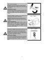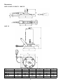
1
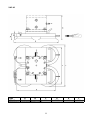
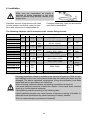
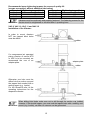
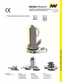
Assembly and Operating Instructions
Aug. 2013
Netter Vacuum-Fixing-Devices
BA Nr. 1386E
Page 1/24
These operating instructions apply for:
VAC 8
VAC 10
VAC 11
VAC 12
VAC 13
VAC 15
VAC 20
VAC 30
VAC 40
Table of Contents
1 GENERAL NOTES
3 2 SAFETY
5 3 TECHNICAL DATA
7 4 DESIGN AND FUNCTIONING
12 5 TRANSPORT AND STORAGE
13 6 INSTALLATION
14 7 START-UP / OPERATION
21 8 SERVICE / MAINTENANCE
22 9 TROUBLESHOOTING
23 10 SPARE PARTS
24 11 ACCESSORIES
24 12 WASTE DISPOSAL
24 13 ENCLOSURES
24 Scope of delivery
The VAC are delivered with the following
components as standard:
•
Vacuum fixing device (VAC)
•
Operating instructions
•
Packaging
•
From series VAC 11 safety rope
Check the packaging for possible signs of
transport damage. In the event of damage
to the packaging, check that the contents
are complete and undamaged. If there is
any damage, inform the shipping agent.
Compare the scope of the delivery with the
delivery note.
For changes to the scope of delivery
please refer to the delivery note.
2
1 General notes
Information on the operating instructions
Use and storage of the operating
instructions
Before use of the Vacuum fixing device of
the series VAC read this operating manual
carefully. It is the basis for any action taken
with regard to the VAC and may be used
for training purposes. The operating
manual should subsequently be stored
near the VAC.
Limitation of liability
All technical information, data and
instructions on installation, operation and
maintenance in these operating instructions
are based on the latest information
available at the time of printing and take
into account our past experience to the best
of our knowledge.
No claims can be derived from the
information, illustrations and descriptions in
these operating instructions.
Target group
The target group of these operating
instructions is qualified technical personnel
from the mechanical engineering sector
who have a basic knowledge of pneumatics
and mechanics.
Installation, commissioning, maintenance,
fault elimination and disassembly of the
VAC must only be performed by persons
who have been instructed in the proper
handling of the units.
Persons who have not been instructed
accordingly must not carry out any works
on the VAC.
The manufacturer does not assume liability
for damages resulting from:
• failure to observe the operating
instructions
• improper use
• unauthorized repairs
• technical modifications
• use of inadmissible spare parts
Translations are made to the best
knowledge. kÉííÉêVibration does not
assume liability for translation errors, even
if the translation was made by us or on our
behalf. Only the original German version is
binding.
Copyright
This documentation is subject to copyright.
All rights e.g. for translation, photo-mechanical
reproduction, printing or reproduction (e.g.
data processing, data carriers and data
networks) of this operating manual, or parts
thereof,
are
strictly
reserved
to
kÉííÉêVibration.
3
The following instruction and warning symbols are used in these operating instructions.
DANGER
referring to a possible risk, which, if not avoided, can
result in death or serious injury.
CAUTION
referring to a possible risk, which, if not avoided, can
result in serious injury and/or equipment damage.
IMPORTANT
note with especially useful information and tips.
ENVIRONMENTALLY
refers to the obligation of an environmentally friendly
FRIENDLY
disposal
DISPOSAL
Information on the VAC
Netter vacuum fixing devices of series
VAC for pneumatic vibrators are in strict
compliance with the EC Machine Directive 2006/42/EC. The standard DIN
EN 12100 has been observed in particular.
Special features
• Quick mounting without bolting or
welding
• Strong connection due to high vacuum
• Can also be used on curved and uneven surfaces
• optional air economizer
4
2 Safety
Designated use:
Vacuum fixing devices of series VAC are
used for quick fastening of vibrators to
smooth and, to a limited extent, also to
rough and curved surfaces.
They are used in combination with vibrators for the emptying of transport containers or drums, for the cleaning of pipes etc.
Vacuum fixing devices are used where
conventional fastening methods for vibrators fail, frequent relocation of vibrators is
required and welding or bolting is not possible.
Any other use is considered improper use.
There are no built-in safety devices.
Qualification of the personnel:
Assembly, start up, maintenance and
repair of the impactors must be
performed only by authorized qualified
personnel.
Any handling of the pneumatic impactors
lies within the responsibility of the operator.
Accessories which ensure the correct
operation and safety must provide a
protection type required for the specific
use.
CAUTION
kÉííÉêVibration does not assume liability for damage or injury resulting
from technical modifications to the product or failure to observe the
instructions and warnings in this operating manual.
CAUTION
Not every pneumatic vibrator is suitable to the vacuum fixing device. Applicable
vibrators are listed in chapter 6 „Mounting of vibrator and hose set“.
When choosing a different vibrator a preceding consultation is required.
Source of danger:
In case of an unexpected pressure drop the vacuum
fixing devices may come loose.
Possible consequences of non-observance:
A fixing device dropping down can cause bodily injury
and/or damage to property.
DANGER
Avoiding the danger:
The vacuum fixing devices VAC 8 and VAC 10 are by
customer secured against drop down.
From series VAC 11 the vacuum fixing devices are
fitted with an adjustable safety rope. This rope must
be pre-tensioned as short as possible using a bulldog
grip. Should a holder come loose it should never drop
into a slack rope.
5
Source of danger:
Faulty hose connections.
Possible consequences of non-observance:
A pressurized hose coming loose can cause severe injury.
DANGER Avoiding the danger:
The hose lines must be securely connected. This
must be checked at regular intervals and the
screw connections have to be retightened if necessary.
Source of danger:
Vibrators bolted to vacuum fixing devices may
come loose by the effect of vibration.
Possible consequences of non-observance:
Falling parts can cause damage to persons and
material.
DANGER Avoiding the danger:
Screw retention components and/or Loctite or
similar must be used. Screw connections must
be checked and, if necessary, retightened after
1 hour of operation and then at regular intervals
(normally every month).
Source of danger:
With parts of smaller cross section there is a risk
that a vacuum fixing device may come loose.
Possible consequences of non-observance:
A fixing device dropping down can cause bodily
injury and/or damage to property.
DANGER
Avoiding the danger:
The vacuum fixing device must not be mounted
on round components, which have a smaller diameter than permitted in chapter 3 “Technical
data“.
6
Jan. / Feb. / ...
3 Technical data
Type
Generated Generated Weight
Air
suction
vacuum
consumppower*
tion
[N]=
[kg]=
[bar]=
[l/min]=
Noise
level**
[dB(A)]=
recommended
minimum diameter
for
round containers
[mm]
4 bar 6 bar 4 bar 6 bar
340
481
VAC 8 + HG 10 N 0,60 0,85
4 bar 6 bar 4 bar 6 bar
0,95
40
60 72
72
110
VAC 8 + HG 10 S 0,60 0,85
340
481
1,20
20
22
72
72
110
VAC 10 + HG 10 N 0,60 0,85
465
658
1,05
40
60
72
72
110
VAC 10 + HG 10 S 0,60 0,85
465
658
1,30
20
22
72
72
110
VAC 11 + HG 10 N 0,60 0,85
710 1.005
1,25
40
60
74
74
110
VAC 11 + HG 10 S 0,60 0,85
710 1.005
1,50
20
22
74
74
110
VAC 12 + HG 15 N 0,60 0,85 1.250 1.770
2,85
60
122
74
74
350
VAC 12 + HG 15 S 0,60 0,85 1.250 1.770
3,20
29
36
74
74
350
VAC 13 + HG 15 N 0,60 0,85 1.362 1.930
4,20
110
170
74
74
850
VAC 13 + HG 15 S 0,60 0,85 1.362 1.930
4,55
41
52
74
74
850
VAC 15 + HG 15 N 0,60 0,85 1.476 2.091
3,40
110
170
74
74
650
VAC 15 + HG 15 S 0,60 0,85 1.476 2.091
3,75
41
52
74
74
650
VAC 20 + HG 15 N 0,60 0,85 2.724 3.859
7,25
110
170
74
74
850
VAC 20 + HG 15 S 0,60 0,85 2.724 3.859
7,60
41
52
74
74
850
VAC 30 + HG 30 N 0,60 0,85 4.086 5.789
11,50
110
170
74
74
1.500
VAC 30 + HG 30 S 0,60 0,85 4.086 5.789
12,00
49
60
74
74
1.500
VAC 40 + HG 40 N 0,60 0,85 5.448 7.718
20,00
220
340
74
74
1.500
* Maximum suction power at 5 bar. For operation of a vibrator a higher pressure may be required.
**The noise level was measured at a distance of 1 m without vibrator. The noise level of vibrators is in most cases higher.
Admissible operating conditions
Drive medium
Clean (Filter ≤ 5 µm, quality class 3 according to DIN ISO 8573-1), compressed air or nitrogen.
Unfiltered air will cause damage to the mounted vibrators.
IMPORTANT
Lubrication
VAC fixing devices do not require lubrication.
For the mounted vibrator lubricated compressed air may be specified. Please
refer to the corresponding operating instructions for the vibrator.
Operating pressure
4 bar to 6 bar*
Operating pressures must not be exceeded or fall short of.
Ambient temperature
-10°C to 60°C
The admissible ambient temperatures must not be exceeded or fallen short of
during operation.
*) Higher operating pressures and temperatures are only permitted after consultation and written confirmation by
application engineers of kÉííÉêVibration.
7
Dimensions:
VAC 8 / VAC 10 / VAC 11 / VAC 12
VAC 13
Type
VAC 8
VAC 10
VAC 11
VAC 12
VAC 13
A
19
22
20
25
70
B
8
8
5,5
10
30
C
150
200
300
300
186
All dimensions in [mm] - measurement X depending on vibrator
8
D
127
175
276
268
241
E
30
26,5
26
68
195
F
55
55
55
100
197
VAC 15 / VAC 20
Type
VAC 15
VAC 20
A
50
70
B
25
30
C
345
425
All dimensions in [mm] - measurement X depending on vibrator
9
D
290
370
E
100
150
F
150
200
VAC 30
Type
VAC 30
A
70
B
30
C
396
All dimensions in [mm] - measurement X depending on vibrator
10
D
339
E
426
F
370
VAC 40
Type
VAC 40
A
70
B
25
C
426
All dimensions in [mm] - measurement X depending on vibrator
11
D
375,5
E
425
F
370
4 Design and Functioning
Vacuum fixing device
A vacuum fixing device mainly consists of a base
plate, a 2/2-way ball valve, a vacuum nozzle and
suction cups. When operating the 2/2-way ball valve
the vacuum nozzle generates a vacuum. By this the
suction cups of the vacuum fixing device adheres to
the mounting surface by suction.
Functional unit
Hose set, vacuum fixing device and vibrator together
form a functional unit. The vibrator is tightly bolted to
the vacuum fixing device. Vibrator and vacuum fixing
device are supplied with the necessary energy (compressed air or nitrogen) through the hose set.
vacuum nozzle
2/2-way ball valve
suction cups
(in this example 2x)
hose set
Vibrator
Connection
between hose set
and compressed
air source
The hose set is normally available in two different designs:
Hose set "Standard" HG .. N and hose set "Economy Air Supply" HG .. S:
Hose set HG ... N
3/2-way slide valve
The vacuum fixing device (opened main valve - customer) will always be under pressure, when the
pressure is applied.
VAC
Vibrator
The vibrator is switched on and off by actuation of
the manually operated 3/2-way slide valve.
VAC
Hose set HG ... S
In addition to the standard function (see hose set
"Standard" HG .. N) the hose set „Economy Air
Supply“ HG .. S has an economy switch position.
With the vibrator switched off the compressed air
consumption can be reduced by approx. 30% in
comparison to the standard version by means of a
restrictor. This compressed air reduction makes
sense, because the "holding function" does not require the totally available compressed air. The totally available compressed air is only needed for operation of the vibrator.
Hose set HG with DRV
Both versions of the hose-sets (N and S) are
available with throttle control valve (DRV) and
recommended by kÉííÉêVibration.
Means of this valve, the pressure which is applied to the vibrator may be adjusted. Thus, there
is the possibility of the speed of the vibrator and
the impact frequency of the vibrator to adjust.
3/2-way slide valve
Vibrator
Rückschlagventil
VAC
Drossel
Vibrator
DRV
VAC
Vibrator
DRV
VAC
12
5
Transport and Storage
Check the packaging for possible signs of transport damage. In the event of
damage to the packaging, check that the contents are complete and undamIMPORTANT aged. If there is any damage, inform the shipping agent.
The vacuum fixing devices are packed
ready for assembly. The type designation
is stamped on the base plate (VAC 8,
VAC 10, VAC 11, VAC 12 and VAC 13) or
engraved (VAC 15, VAC 20, VAC 30 and
VAC 40).
Protect the vacuum fixing devices from excessive exposure to UV radiation.
The vacuum fixing devices should be
stored in boxes in a dry and clean environment.
When restocking all openings must be
closed.
When ordering a vacuum fixing device in
connection with hose set and vibrator,
these components will be completely assembled, unless specified differently. Special transport conditions are not specified.
The storage temperature should be
between -20 and +80°C. (This does not
apply to the operating temperature).
Packaging
The packaging protects the unit from
transport damages. The material of the
packaging has been selected based on
environmentally
and
disposal-friendly
aspects and can therefore be recycled.
Recycling the packaging reduces raw
material consumption and the waste
volume.
13
6 Installation
CAUTION
Make sure the compressed air supply is
switched off during installation or any other
work on vacuum fixing devices, vibrator or air
supply lines.
Complete vacuum fixing devices with hose
set and vibrator are directly ready for operation after connection to compressed air.
If ordered separately, hose set and vibrator
must first be assembled.
.
The following vibrators can be mounted to the vacuum fixing devices:
Suitable vibrators
NCB NCR NCT
NTK
NTS
NTP
PKL
8AL,15X,
120 HF, 120 NF*
VAC 8 +HG 10 N
1, 2
1, 2
25**
16, 18AL
180 HF, 180 NF*
VAC 8 +HG 10 S
180 HF, 180 NF*
VAC10+HG 10 N
15X,
25**
190
1, 2, 3 3
3, 4
18AL
250 HF, 250 NF*
VAC10+HG 10 S
180 HF, 180 NF
190
VAC11+HG 10 N
3, 5 10
5, 10
18AL
250 HF, 250 NF
450**
VAC11+HG 10 S
350 HF, 350 NF
450**
VAC12+HG 15 N
10, 20 22 15, 29
25AL
32**
100/01, 75/01, 50/01**
740**
VAC12+HG 15 S
740, 2100
VAC13+HG 15 N
10, 20 22 15, 29
75/01, 50/01
32**
5000
VAC13+HG 15 S
250 HF,250 NF,350 HF,350 NF
VAC15+HG 15 N 10, 20 22 15, 29
18AL, 25
32, 48*
740
75/01, 50/01, 70/02*
VAC15+HG 15 S 50, 70 57* 55, 108*
VAC20+HG 15 N
2100
57 55, 108
70/02, 54/02, 50/04*
32, 48
5000
VAC20+HG 15 S
NVG 49,
5000
VAC30+HG 30 N
55, 61
126,
120
50/04, 50/08*
250
NVG 82,
VAC30+HG 30 S
84*
50/08*, 50 /10*
VAC40+HG 40 N
Type
*Depending on application, please consult kÉííÉêVibration.
DANGER
** Adapter plate required, please add to your order!
Not every pneumatic vibrator is suitable to the vacuum fixing device. With drill patterns different to the ones for the above listed units the internal pilot bores may be
damaged. The above mentioned combinations (fixing device/vibrator) have been
tested and can be used without any limitations.
When choosing a different vibrator a preceding consultation is required.
Use screw retentions and nuts to fasten the vibrator. Use a liquid screw retention
agent (e.g. Loctite) against loosening.
Use tightening torques according to the following table.
Higher tightening torques may cause fracture of screws or tearing of threads. Inadequate screw connections may cause loosening of units by vibration.
This can cause damage to persons and material!
14
Recommended mean tightening torques for screws of quality 8.8
(screws as supplied, without additional lubrication):
Tightening torque [Nm]
Tightening torque [Nm]
Thread
Thread
M 6
10
M 12
80
M 8
23
M 16
190
M 10
48
M 20
380
Vibrators must be cautiously and properly fastened. The fastening screws for the
IMPORTANT vibrator must be retightened or checked after 1 operating hour.
VAC 8, VAC 10, VAC 11 and VAC 12
Installation of the Vibrator:
In order to mount vibrators
NCT two tapped blind holes
must be drilled.
rubber
If a compressed air operated
piston vibrator of series NTS
or NTK is to be mounted, we
recommend the use of an
adapter plate.
adapter plate
rubber
Otherwise one hole must be
drilled into the suction cup and
the tapped hole sealed with a
sealing agent (e.g. Loctite).
For the thread X refer to the
operating instructions for the
respective vibrator.
rubber
When drilling blind holes make sure not to drill through the suction cup (rubber).
However, if this should happen, you must seal the tapped holes with a sealing comIMPORTANT pound (e.g. Loctite), as other no vacuum can be generated.
15
VAC 13, VAC 15, VAC 20, VAC 30 and VAC 40
Installation of the Vibrator:
3. Drill through-holes (diameter depending
In order to mount the vibrator to a VAC 13,
on type of vibrator - see operating inVAC 15 or VAC 20 socket head cap
structions for vibrator).
screws acc. to DIN 7991 are required. The
Countersink bores from bottom side of
assembly can be performed as follows:
base plate (side of suction cup) acc. to
1. Unscrew the suction cups.
DIN 74-Bf....
2. Determine and mark the necessary bore
4. Fasten the vibrator using the specified
holes (commonly used bore pitches
socket head cap screws. For this purhave already been marked with a centre
pose use common screw retentions.
punch, see template VAC 15 and VAC
5. Assemble the suction cups in the correct
20).
position.
For assembly of the PKL 740 to the VAC 15 an adapter plate is required, if the
IMPORTANT inlay EE is not used.
Template VAC 13
Do not drill through
this aerea!
16
Template VAC 15
Do not drill through
this aerea!
Round Plate
Template VAC 20
Round Plate
Do not drill through
this aerea!
17
Template VAC 30
Do not drill through
this aerea!
VAC 40
Installation of the Vibrator:
The VAC 40 consists of two VAC 20, which
are connected by an adapter plate. The
vibrator is mounted to the adapter plate.
For the fastening of a compressed air operated piston vibrator series NTS 50/10 the
adapter plate has four through holes. For
the fastening of any other vibrator you
should consult kÉííÉêVibration beforehand.
Installation of the VAC on the lifting device
Due to its own weight, the vacuum fixing
device may only be lifted with suitable lifting
device. When lifting the vacuum fixing device an eyebolt M16 is available.
18
Vacuum fixing devices should be used in combination with the following hose sets:
Hose set for PKL
Type
Hose set (except PKL)
VAC 8
HG 10 N or HG 10 S
VAC 10
HG 10 N or HG 10 S
VAC 11
HG 10 N or HG 10 S
HG 10 N or HG 10 S
VAC 12
HG 15 N or HG 15 S
HG 10 N or HG 10 S
VAC 13
HG 15 N or HG 15 S
HG 10 N or HG 10 S
VAC 15
HG 15 N or HG 15 S
HG 10 N or HG 10 S
VAC 20
HG 15 N or HG 15 S
HG 10 N or HG 10 S
VAC 30
HG 30 N or HG 30 S
HG 10 N or HG 10 S
VAC 40
HG 40 N
Throttle control valves (DRV) are recommended for use of a hose set.
Example of Hose set HG N with DRV
Manual slide valve
DRV
connection
Compressed
air supply
connection
Vibrator
connection
Vacuum fixing
devices
Example of Hose set HG S with DRV
connection
Vibrator
connection
Compressed
air supply
connection
Vacuum fixing
devices
throttle screw
(air economizer function)
19
Connection of power supply
Supply line:
The pressure loss increases with the hose
length. The following recommendations refer to hose lengths of max. 3 m to the next
bigger hose cross section. For longer
supply lines we recommend the use of bigger cross-sections, whereby the supplied
hose socket can no longer be used.
Minimum cross-sections for hoses
A too small cross-section does not enable a sufficient vacuum.
CAUTION
Type
HG 10 N / S
HG 15 N / S
HG 30 N / S
HG 40 N
Hose socket
1/4“
3/8“
1/2“
1/2“
Hose size
NW 6
NW 9
NW 12
NW 12
Safeguard with safety rope
Before mounting locate a secure attachment point (e.g.
an eye bolt) where you can hook the safety rope of the
vacuum fixing device to attach it on your container or
your construction.
DANGER
This rope must be pre-tensioned as short as possible
by using a rope clamp. Should a vacuum fixing device
come loose it must not drop into a slack rope.
Checklist for installation:
1) Install the vibrator. Mounting screws secure.
2) Install hose set.
3) Install maintenance unit (filter, regulator and lubricator possibly) and
valve.
4) Lock the fastening screws with glue (e.g. Loctite).
5) Glue the air supply lines.
6) Observe the information on hose length and diameter.
7) Connect safety cable!
20
7 Start-up / operation
DANGER
In case of an unexpected pressure drop the vacuum fixing devices may come loose. Therefore, they are always
secured against falling down.
For 8 VAC and 10 VAC additional adapter plates and
safety ropes are available.
From series VAC 11 the vacuum fixing devices are fitted
with an adjustable safety rope.
Adjust the desired vibrator frequency
with a pressure regulator (option - e.g.
part of a maintenance unit).
When using a vacuum fixing device with
hose set HG .. S you may activate the
Economy Air Supply function. For this
purpose turn the throttle screw in clockwise direction, until the fixing device can
be easily moved by hand. Then start the
vibrator by actuating the manual 3/2-way
slide valve on the hose set, the full vacuum will be generated.
Handling:
First secure the vacuum fixing device
against falling down. Then you have to
check the hose connections. Turn on the
compressed air supply for the vacuum fixing device and the vibrator. Then attach
the vacuum fixing device to the desired
location and actuate the 2/2-way ball valve
on the vacuum fixing device to generate
the required vacuum in the suction cup.
Check the vacuum fixing device for tight
and secure attachment.
If the fixing device can be loosened by
hand, you should increase the pressure
(e.g. on maintenance unit with pressure
regulator).
Then start the vibrator by actuating the manual 3/2-way slide valve on the hose set and
adjust the lubricator.
The vacuum fixing device can be operated with filtered compressed air or nitrogen. For operation of certain vibrators a lubricated drive medium is specified.
IMPORTANT Adjust the lubricator while the vibrator is running. Exact details concerning can
be taken from the operating instructions for the vibrator.
When relocating the vacuum fixing device with hose set HG .. S to another surface the economy air supply function must be readjusted or checked on the reIMPORTANT strictor screw.
Checklist for commissioning:
1) Secure the VAC against falling down?
2) Check all hose connections before opening the air supply.
3) Turn on the compressed air, if necessary.
4) Position the vacuum fixing device to the desired place.
5) Adjust the lubricator, if present.
6) If necessary adjust the required frequency on the pressure regulator.
7) The compressed air feed lines, the plug screws and the fixing screws have to
be tightened and checked.
21
8 Service / Maintenance
CAUTION
Before starting inspection and service works shut
off the compressed air supply and secure it
against unintended activation!
The drive medium must be clean (filter ≤ 5 µm,
class 3). Unfiltered compressed air leads to high
wear, blocked silencers or complete break-down of
the impactor. The maintenance intervals will be
shorter.
IMPORTANT
For more details, refer to the
instructions for the relevant vibrator.
operating
≤ 5 µm
Recommendation: Filter
Maintenance plan
Maintenance must be performed monthly.
Screw connections
Securing
rope
Cleaning
Suction
cups
Vacuum
nozzle
DANGER
Lubricator
Silencer
The screw connections must be checked after an hour of
operation (after first startup), then at regular intervals and if
necessary be tightened and secured with Loctite.
If the safety rope has been extremely loaded by the vacuum
fixing device dropping down, it should be replaced by a new
one.
Vacuum fixing devices may be cleaned from outside with
pressurized water. After cleaning run the unit for a short
moment.
The suction cups must be permanently checked for wear and
need to be replaced if necessary.
The vacuum nozzle may be clogged by contaminated
compressed air. In this case the nozzle must be disassembled
and cleaned.
On VAC 8, VAC 10, VAC 11 and VAC 12 the externally
vacuum nozzle is easy to disassemble and clean.
Disassembly and cleaning of vacuum nozzles on VAC 13,
VAC 15, VAC 20, VAC 30 and VAC 40 should only be performed by kÉííÉêVibration.
With a lubricator connected in series make sure that the lubricator works as specified (contents decreases? number of
drops/min? Fill oil if necessary).
Clean if necessary. The maintenance intervals depend mainly
on the purity of the drive medium and the ambient conditions.
Filter of the
Replace filter insert, empty the filter when required or clean the
maintenance
filter insert (wash out).
unit
22
9 Troubleshooting
Fault
Possible cause
Vacuum
Air supply
fixing
devices
does not
generate
any
vacuum
Silencer on fixing
device clogged
Vacuum nozzle
clogged
Vacuum
fixing
devices
slips
during
vibration
Trouble shooting
Check pressure before
holder. Hose set correctly
assembled? For economic
air supply check setting of
restrictor. Hoses kinked?
Sufficient cross-section of
supply line?
Performance test without
silencer.
Remedy
Adjust pressure to 3 bar to 6 bar.
Assemble hose set correctly.
Adjust restrictor.
Route hoses without kinks.
Enlarge
the
supply
line
cross-section.
Wash out or replace, as required
Clean (procedure is described in
chapter
„Maintenance
and
Repair“.)
Suction surface Is the suction surface air- If yes, the vacuum fixing device
permeable and/or rough? is not suitable for this application.
Air supply
Hoses kinked?
Route hoses without kinks.
Silencer clogged
Wash or replace
Vacuum nozzle
Clean (procedure is described in
clogged
chapter
„Maintenance
and
Repair“.)
Suction surface Is the suction surface air- If yes, the vacuum fixing device
permeable?
is not suitable for this application.
Remove the respective layers.
Is the suction surface oily,
greasy or wet?
Suction
cups
Replace suction cups
worn
Extremely
Mount fixing device to the elastic
massive
base
base
between
stiffeners
(rebounds)
(diaphragm effect).
23
10 Spare parts
When ordering spare parts please give the following details:
1. Required quantity
2. Description and position of the spare part (see spare parts list)
3. Type of unit
11 Accessories
The following accessories are available for vacuum fixing devices (on request):
Description
Remark
Hose material and fittings For supply and discharge of compressed air in various qualities
and dimensions
3/2- or 2/2-way valves
For electric, pneumatic and manual control
For rotary speed control, manually adjustable or pneumatically
Restrictor valves
controllable (for remote control)
Service units
Filter, regulator, lubricator
Duty/pause control
Electric or pneumatic for interval operation
Some vacuum fixing devices are also available as special versions, e.g. with stainless steel plate, for extreme temperature
SPECIAL DESIGNS:
ranges with suction cups made of silicone.
Further information on request.
12 Waste disposal
The parts are to be correctly disposed of, depending on the material.
Material specifications:
VAC 8-12
VAC 13-40
Steel
Aluminium
Rubber
Brass, nickel plated
PVC
Clamping plate
Fittings
Vacuum nozzle, handgrip
Clamping plate, handgrip
Suction cups
(black or anthracite)
Suction cups
(black or anthracite)
Fittings
Vacuum nozzle, Fittings
seals
seals
Special units: Material on request (e.g. suction cups made of silicone)
All units can be disposed off through kÉííÉêVibration.
The valid disposal prices are available on request.
13 Enclosures
Further information available on request:
Leaflet no. 15 (VAC), and more
24