1
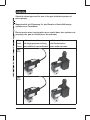
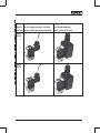
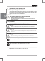
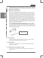
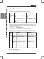
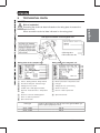
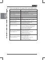
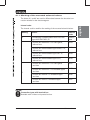
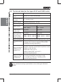
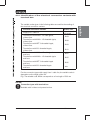
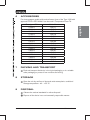
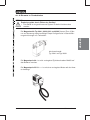
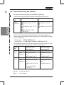
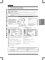
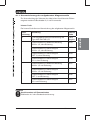
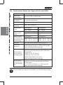
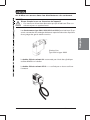
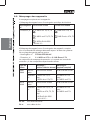
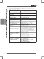
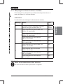
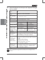
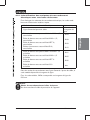
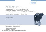
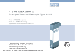
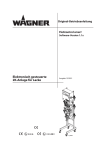
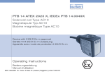
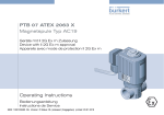
PTB 03 ATEX 5014 X
Type 0641 / 2832 / 6013 / 6022
Solenoid valve for use in the gas feedback systems
for petrol pumps
Magnetventile zum Einsatz in
Gasrückführungssystemen von Tanksäulen
Electrovannes pour emploi dans systèmes de
recyclage de gaz de distributeurs de carburant
Example
Beispiel
Exemple
Type 0641
Operating Instructions
Bedienungsanleitung
Manuel d‘utilisation
We reserve the right to make technical changes without notice.
Technische Änderungen vorbehalten.
Sous réserve de modifications techniques.
© 2003 - 2011 Bürkert Werke GmbH
Operating Instructions 1107/07_EU-ML_00804694 / Original DE
Solenoid valves approved for use in the gas feedback systems of
petrol pumps
Magnetventile mit Zulassung für den Einsatz in Gasrückführungssystemen von Tanksäulen
Electrovannes avec homologation pour emploi dans des systèmes de
recyclage des gaz de distributeurs de carburant
Valve
Ventil
Vanne
with cast-on cable
mit eingegossener Leitung
avec câble de raccordement
with terminal box
mit Klemmkasten
avec boîte à bornes
Type
0641
Type
2832
03 ATEX5014 X - 3
Valve
Ventil
Vanne
with cast-on cable
mit eingegossener Leitung
avec câble de raccordement
Type
6013
Type
6022
4 - 03 ATEX5014 X
with terminal box
mit Klemmkasten
avec boîte à bornes
DEVICES WITH II 1 / 2 G EX M AND / OR
II 1 / 2 G EX EM-APPROVAL
PTB 03 ATEX 5014 X
1 GENERAL INFORMATION..........................................................................................................6
1.1 The operating instructions......................................................................................... 6
1.2 Symbols......................................................................................................................... 6
1.3 Correct utilisation......................................................................................................... 7
1.4 General Safety Instructions....................................................................................... 8
1.5 General Information..................................................................................................... 9
2 APPLICATION CONDITIONS FOR THE UNITS........................................................... 10
2.1 Special conditions.....................................................................................................10
2.2 Marking of the units...................................................................................................12
3 TECHNICAL DATA....................................................................................................................... 13
3.1 Technical data for the type 0641 and 2832 units..............................................14
3.2 Technical data for the type 6013 and 6022 units..............................................16
4 INSTALLATION AND COMMISSIONING......................................................................... 18
4.1 Assembly.....................................................................................................................19
4.2 Commissioning...........................................................................................................20
5 MAINTENANCE AND FAULTS.............................................................................................. 20
5.1 Faults............................................................................................................................20
6 ACCESSORIES............................................................................................................................ 21
7 PACKING AND TRANSPORT................................................................................................ 21
8 STORAGE........................................................................................................................................ 21
9 DISPOSAL...................................................................................................................................... 21
03 ATEX5014 X - 5
english
CONTENT:
1
GENERAL INFORMATION
english
1.1 The operating instructions
The operating manual describes the whole life cycle of the appliance. Store
this manual in such a way that is easily accessible to every user and is available to every new owner of the appliance.
WARNING!
The operating manual must be read and understood.
• Read the operating manual carefully.
• Pay particular attention to the sections Intended Use and General
Safety Precautions!
1.2 Symbols
The following symbols are used throughout this manual:
DANGER!
High risk
• Serious or fatal injuries if the safety precautions are not observed.
WARNING!
Middle risk
• Injuries or serious equipment damage if the safety precautions are not
observed.
CAUTION!
Low risk
• Equipment damage if the safety precautions are not observed.
NOTES!
indicates important additional information, tips and recommendations.
NOTES!
refers to information in this operating manual or in other
documents.
indicates a work step which you must carry out.
6 - 03 ATEX5014 X
The device may only be used for the applications indicated in the chapter
Operating conditions for the devices, and only in connection with third-party
devices or components recommended or approved by Bürkert. Observe
the instructions in this operating manual, as well as the conditions of use
and permissible data specified in the chapter Operating conditions for the
devices.
The proper and safe function of the system depends on proper transport,
storage and installation, and on careful operation and maintenance.
• The solenoid valves may only be used for the control of explosive steam/
gas mixtures of flammable liquids of Explosion Group IIA and Temperature
Classes T1 to T3 in accordance with EN 60079-14.
• The solenoid valves may only be set up in petrol pumps between the
pump valve and the gas feedback pump. The setting-up of the solenoid
valve must be based on EN 60079-14.
• The solenoid valves are to be used in the gas feedback equipment of
filing stations, for the control of explosive steam/gas mixtures of flammable
liquids of the Danger Classes A I, A II and B, insofar as the liquids belong
to Explosion Group IIA and the Temperature Classes T1 to T3 according
to EN 60079-14 and the provisions and conditions defined in the Qualification Test Certificate are complied with.
• The protection class used is the Encapsulation Ex m for coils with cable
connection or encapsulation with increased safety Ex em for coils with
terminal boxes.
• Any other utilisation, or a utilisation going beyond this use will be regarded
as improper. Bürkert will accept no liability for any damage resulting from
such use. The user must bear all the risk alone.
1.3.1Approvals of the electromagnets
Valve type
Electromagnet
Approval
0641
2832
64.-
PTB 02 ATEX 2094X
6013
6022
Typ AC10-..-.-PD47 +
PD53 + PD60 + PD66
PTB 00 ATEX 2129X
03 ATEX5014 X - 7
english
1.3 Correct utilisation
1.4 General Safety Instructions
english
DANGER!
Risk of explosion if the device is opened!
• The device is a sealed system. It must not be opened.
DANGER!
Electrical power supply in the system!
Acute risk of injury from hazardous structure-borne voltage!
Risk of damage to the device due to short circuit!
• Work on the electrical system may only be carried out by qualified
electricians.
• Before starting work, switch off the power supply and secure to prevent it being switched on again!
• Observe the applicable accident prevention and safety regulations for
electrical devices!
WARNING!
Pressurised system!
Interventions in the pneumatic system represent an acute risk of injury.
• Work on the pneumatic system may only be carried out by qualified and
instructed personnel using appropriate tools.
• First switch off pressure before disconnecting lines and valves.
• Observe the flow direction during installation!
• Observe the applicable accident prevention and safety regulations for
pneumatic systems!
WARNING!
General hazards!
Hazards can lead to precarious situations.
• Unintentional operation or impermissible damage can lead to generally
dangerous situations including physical injury. Take appropriate measures to prevent unintentional operation or impermissible damage!
• The generally recognised safety engineering rules apply for the planning and operation of the device. These rules must be observed.
NOTES!
The device has been developed in accordance with the acknowledged
safety engineering rules and corresponds to the state of the art. However,
risks may arise. Operate the device only in a proper and safe state and in
accordance with the operating manual.
8 - 03 ATEX5014 X
1.5 General Information
1.5.1Contact address
english
Germany
Bürkert Fluid Control Systems
Sales Center
Chr.-Bürkert-Str. 13-17
D-74653 Ingelfingen
Tel. + 49 (0) 7940 - 10 91 111
Fax + 49 (0) 7940 - 10 91 448
E-mail: [email protected]
International
Contact addresses can be found on the final pages of the printed operating
instructions.
And also on the Internet under: www.burkert.com
1.5.2Warranty
The warranty is only valid if the device is used as intended in accordance
with the specified application conditions.
1.5.3Approvals
The EC Type Examination Certificate PTB 03 ATEX 5014 X has been drawn
up by the
PTB (Physikalisch Technische Bundesanstalt)
Bundesallee 100
38116 Braunschweig
who also audited the manufacture (CE0102).
1.5.4Information on the Internet
Operating instructions and data sheets for type 0641 (2832/6013/6022)
may be found on the Internet under:
www.buerkert.com
03 ATEX5014 X - 9
2
APPLICATION CONDITIONS FOR THE UNITS
2.1 Special conditions
english
2.1.1Short-circuit protection
As a short-circuit protection, each magnet must be connected in series
with a fuse corresponding to its rated current (max. 3 x Ib according to IEC
60127-2-1) or a motor protector switch with a fast-acting short-circuit and
thermal trip (set to the rated current). For very small rated currents for the
magnets, the fuse with the smallest current value according to the above-mentioned IEC standard will suffice. This fuse may be mounted in the
associated supply unit or must be connected in series separately. The rated
voltage of the fuse must be equal to or larger than the quoted nominal voltage of the magnet. The switch-off capability of the fuse cartridge must be
equal to or greater than the maximum theoretical short-circuit current at the
installation location (normally 1500 A).
For the valve types 0641, 2832, 6013 and 6022 in the versions without
fuses, the short-circuit protection must be guaranteed by the operator. For
the version with a fuse, the latter is built into the terminal box of the device. A
more detailed description of the models can be found in the Technical Data
section of the various models.
Fuse ...... A
2.1.2Conformity
In accordance with the EC Declaration of conformity, Type 0641, 2832,
6013 and 6022 is compliant with the EC Directives.
2.1.3Standards
Conformity with the EC Directives is verified by the following standards.
EN13463-1, EN13617-1
2.1.4Operational temperature range
Please note the operational temperature range listed for each type in the
Electrical Data!
10 - 03 ATEX5014 X
DANGER!
Risk of explosion if the device is opened!
• The valves may only be dismantled by the manufacturer. The always
represent a closed system!
The Type 0641, 2832, 6013 and 6022 solenoid valves (Inner Zone 0) are
used for explosive steam/air mixtures in the in gas feedback equipment of
filling stations.
Bolted together as a block
Type 0641 and Type 2832
The magnetic coil 64.- is mounted on the body using 4 sealed M4x59 cylinder screws.
The magnetic coil AC10-..-.-... is secured onto the fitting using a sealed nut.
03 ATEX5014 X - 11
english
2.1.5Use in petrol pumps
2.2 Marking of the units
Two markings are made on the units:
english
1) Marking of the units with the specific approval of the coil
Approval
no.
PTB 00 ATEX 2129X
Protection
type
PTB 02 ATEX 2094X
II 2G Ex m II T4, T5, T6
or
II 2G Ex m II T4, T5
or
II 2G Ex em II T4, T5, T6
II 2G Ex mb e II T4, T5
or
II 2D Ex tD A21 IP65
T -40/-30 °C...
2) Marking of the units with the approval of the complete unit for the control
of explosive steam/air mixture explosive steam/air mixtures in the gas feedback systems of filling stations
- Approval no.:
PTB 03 ATEX 5014 X
- Protection type: II 1/2G Ex m II T3 or II 1/2G Ex em II T3
The composition of the symbol of the protective class is aligned to the protection class of the components used in each case.
Valve
type
0641
2832
6013
6022
Approval
Marking 1
Marking 2
(Magnetic coil)
(Complete unit)
PTB 02 ATEX 2094X
PTB 03 ATEX 5014X
Protection II 2G Ex m II T4, T5
type
or
Approval
II 2G Ex mb e II T4, T5
II 1/2G Ex em II T3
PTB 00 ATEX 2129X
PTB 03 ATEX 5014X
Protection II 2G Ex m II T4, T5, T6
type
or
II 2G Ex em II T4, T5, T6
or
II 2D Ex tD A21 IP65
T -40/-30 °C ...
Ex em
with terminal box
Ex m
with 3 meters of cable
12 - 03 ATEX5014 X
II 1/2G Ex m II T3
or
II 1/2G Ex m II T3
or
II 1/2G Ex em II T3
TECHNICAL DATA
DANGER!
Risk of explosion!
Exceeding the technical data indicated on the rating plate increases the
explosion risk!
Never exceed the technical data indicated on the rating plate!
PTB approval number of the magnetic coil
CE designation
PTB certification No.
Fuse
... A
Rating plate of the complete unit
Rating plate of the magnetic coil
Orifice - Sealing material - Body material
Mode of protection / temperature code
Port size for fluid part - Pressure range
Coil type
Voltage (±10 %) - Power
Voltage (±10 %) - power rating
variable code - PTB-Approval number
Serial no. of the coil
Approval - Protection Class - Temperature
class
Ident. no / date of production
Serial no. of the coil /CE designation
Space for barcode
Ident. no / date of production
Space for barcode
Valve type
0641 / 2832
6013 / 6022
Code for the marking of units for use in the gas feedback systems of petrol pumps (Coil size)
PD 36
PD 97
03 ATEX5014 X - 13
english
3
english
3.1 Technical data for the type 0641 and 2832 units
Temperature class
T3
Electromagnet used
Type 64.-, PTB 02 ATEX 2094X
Circuit function of the valve
A = normally closed
Type of current
Universal current (0 Hz ... 60 Hz)
Rated voltage
12 V ... 240 V (±10 %)
Rated current
0.58 ...0.034 A
Power limit at steady state
7W
Maximal permissible ambient Individually mounted -40 °C ... +60 °C
temperature range
Block assembly -40 °C ... +45 °C
Type of protection
Electrical connection
Type of protection / Marking
of the magnetic coil
Type of protection / Marking
of the complete unit
14 - 03 ATEX5014 X
IP 65 according to EN 60529
(DIN VDE 0470 Part 1)
For the marking of the electrical connection
variants, the letters A, L and K are used
according to the Approval for Electromagnets PTB 02 ATEX 2094X
(see following description).
Electrical connection "A":
II 2G Ex mb II T4, T5
Electrical connection "L" and "K":
II 2G Ex mb e II T4, T5
(see following description)
Electrical connection "A ":
II 1 / 2 G Ex m II T3
Electrical connection "L" and "K":
II 1 / 2G Ex em II T3
(see following description)
3.1.1Marking of the mounted solenoid valves
Internal code:
The internal code is used for the marking of the mounted solenoid valves.
Marking
Version
Internal
code
A
- Permanently installed rubber hose line of the
type H05 RN-F3G 0,75
without
data
- Terminal box with M 20 x 1.5 cable gland,
without fuse
JA02
- Terminal box with threaded nipple M 20 x 1.5,
without fuse
JA08
- Terminal box with threaded nipple NPT ½,
without fuse
JA09
- Terminal box with threaded nipple G ½,
without fuse
JA10
- Terminal box with M 20 x 1.5 cable gland
and fuse
JA01
- Terminal box with M 20 x 1.5 threaded nipple
and fuse
JA05
- Terminal box with NPT ½ threaded nipple
and fuse
JA06
- Terminal box with G ½ threaded nipple
and fuse
JA07
L
K
NOTES!
Connection types with terminal box
Available with / without unit protective fuse.
03 ATEX5014 X - 15
english
The letters A, L and K are used to differentiate between the electrical connection variants for the electromagnets.
3.2 Technical data for the type 6013 and 6022 units
english
Temperature class T3
Electromagnet
used
Type AC10, PTB 00 ATEX 2129X
Circuit function of
the valve
A = normally closed
Type of current
Universal current (0 Hz ... 60 Hz)
Rated voltage
12 V ... 400 V (±10 %)
Rated current
Power limit at
steady state
Coil size 5
Coil size 6
0,68 ...0,02 A
0,8 ... 0,02 A
Coil size 5
Coil size 6
7W
9W
Maximal permisCoil size 5
sible ambient temPD47: -30 °C ... +60 °C
perature range
PD60: -40 °C ... +60 °C
Single mounting
Coil size 6
PD53: -30 °C ... +60 °C
PD66: -40 °C ... +60 °C
Type of protection
IP 65 according to EN 60529 (DIN VDE 0470 Part 1)
Electrical connection
Electrical connection variants according to approval
of the type AC 10 electro-magnets PTB 00 ATEX
2129X (see following description).
Type of protection
/ Marking of the
magnetic coil
Type of protection
/ Marking of the
complete unit
The type of protection changes depending on the
electrical connection variants (the components used):
II 2G Ex m II T4, T5, T6 or
II 2G Ex em II T4, T5, T6 or
II 2D Ex tD A21 IP65 T -40/-30 °C ...
(see following description).
The marking changes depending on the electrical
connection variants (the components used):
II 1 / 2 G Ex m II T3 or II 1 / 2 G Ex em II T3
(see following description).
NOTES!
Only individual mounting is permissible for units of the types 6013 and
6022.
16 - 03 ATEX5014 X
The variable codes given in the following table are used for the marking of
the electrical connection variants.
Electrical connection variants
- Supply line / cable lin
- Terminal box with M 20 x 1.5 cable gland,
without fuse
- Terminal box with M 20 x 1.5 threaded nipple,
without fuse
- Terminal box with NPT ½ threaded nipple,
without fuse
- Terminal box with G ½ threaded nipple,
without fuse
- Terminal box with M 20 x 1.5 cable gland
and fuse
- Terminal box with M 20 x 1.5 threaded nipple
and fuse
- Terminal box with NPT ½ threaded nipple
and fuse
- Terminal box with G ½ threaded nipple
and fuse
Variable code
dependet on the
line length
JA02
JA08
JA09
JA10
JA01
JA05
JA06
JA07
For the connection types with supply lines / cable line, the variable code is
dependent on the length of the line.
E.g.: The variable code JW04 corresponds to a line length of 500 mm
NOTES!
Connection types with terminal box
Available with / without unit protective fuse.
03 ATEX5014 X - 17
english
3.2.1Identification of the electrical connection variants with
terminal box
english
4
INSTALLATION AND COMMISSIONING
DANGER!
Danger of explosion!
• The device is a sealed system. The unit must not be dismantled!
The following safety regulations must be observed:
• The surface of the device may develop an electrostatic charge.
In areas with an explosion hazard, the surface of the units may only be
cleaned with a damp cloth!
• Only permanently laid cables and wiring may be inserted.
• The operator must provide suitable stress relief.
• Wires with an outside diameter of 6 to 13 mm may be used. Observe
the maximum thermal loading of the cables or wires to be inserted.
• The inserted break-off seal must be matched to the diameter of the
cable or wire.
• The rated cross-section of the cable or wire strands must be at least
0.75 mm² and may not exceed 2.5 mm².
• The screws for fixing the cover of the terminal box must be tightened
with a torque of 100 Ncm (±5%).
DANGER!
High voltage!
Acute risk of injury from hazardous structure-borne voltage!
Risk of damage to the device due to short circuit!
• Work on the electrical system may only be carried out by qualified
electricians.
• Before starting work, switch off the power supply and secure to prevent it being switched on again!
• Live terminals in the terminal box can cause electric shock, short circuit
or explosion. Switch off the power supply before opening the terminal
box.
• The connecting cables to the electromagnets must be secure, and be
laid so that they are adequately protected from mechanical damage.
• Observe the applicable accident prevention and safety regulations for
electrical devices!
18 - 03 ATEX5014 X
The type 0641, 2832, 6013 and 6022 units may only be installed in petrol
pumps between the pump valve and the gas feedback pump. This use must
be based on EN 60079-14.
Please observe the maximum permissible environmental temperature range.
4.1 Assembly
NOTES!
Installation in any position.
Preferably with solenoid system mounted at the top
Activity
Notes
Clean the pipe runs
Installation in any position
Preferred direction with drive mounted
at the top
Connect a dirt-trap (strainer) upstream
Note the direction of flow!
Screwing on the pipe run
Note the direction of flow!
Installation / Dismounting
Note for types 0641 and 2832
Always connect the earth
conductor!
Note for units with connecting cable
The connecting cable and the coil are
moduled together. They must not be
dismantled!
Make electrical connections
03 ATEX5014 X - 19
english
WARNING!
Pressurised system!
Interventions in the pneumatic system represent an acute risk of injury.
• Work on the pneumatic system may only be carried out by qualified and
instructed personnel using appropriate tools.
• First switch off pressure before disconnecting lines and valves.
• Observe the flow direction during installation!
• Observe the applicable accident prevention and safety regulations for
pneumatic systems!
4.2 Commissioning
english
Before commissioning, ensure that
•
•
•
•
5
The device has been correctly installed,
The connections have been correctly made,
The device is not damaged,
All bolts are securely tightened.
MAINTENANCE AND FAULTS
DANGER!
Hazards due to improper service, repair and maintenance work.
• Service and maintenance work on the device may only be carried out
by authorised and suitably qualified personnel.
• Repair work may only be carried out by the manufacturer!
• When carrying out repair or maintenance work on the system, the valve
must not be opened and the earth connection must not be disconnected!
When operated under the conditions described in these instructions, the
units are maintenance-free.
5.1 Faults
In the event of faults, ensure that
•
•
•
•
•
•
The device has been correctly installed,
The connections have been correctly made,
The device is not damaged,
All bolts are securely tightened.
The electric and pneumatic power supplies are connected,
All pipework is free.
20 - 03 ATEX5014 X
6
ACCESSORIES
For electromagnet models with terminal boxes, fuses of the Type 1058 with
approval PTB 01 ATEX 2064 U can be used in Temperature Class T4.
7
PACKING AND TRANSPORT
8
Order No.
153717
153745
153718
153719
153720
153731
153733
153734
153735
153736
153737
153738
153739
153746
153740
153742
english
Fuse type 1058
0,063 A
0,080 A
0,100 A
0,125 A
0,160 A
0,200 A
0,315 A
0,400 A
0,500 A
0,630 A
0,800 A
1,000 A
1,250 A
1,600 A
2,000 A
3,150 A
Pack and transport the device in its original packaging or in a suitable
other packaging to protect it from moisture and soiling.
STORAGE
Store the unit dry and free of dust and under atmospheric conditions!
9
Storage temperature: -40 ... +55 °C.
DISPOSAL
Observe the national standards for refuse disposal!
Dispose of the device in an environmentally responsible manner.
03 ATEX5014 X - 21
english
22 - 03 ATEX5014 X
GERÄTE MIT II 1 / 2 G EX M BZW.
II 1 / 2 G EX EM-ZULASSUNG
PTB 03 ATEX 5014 X
INHALT:
1 ALLGEMEINES............................................................................................................................. 24
1.1 Die Bedienungsanleitung.........................................................................................24
1.3 Bestimmungsgemäße Verwendung.......................................................................25
1.4 Allgemeine Sicherheitshinweise.............................................................................26
1.5 Allgemeine Hinweise.................................................................................................27
2 EINSATZBEDINGUNGEN DER GERÄTE......................................................................... 28
2.1 Besondere Bedingungen.........................................................................................28
2.2 Kennzeichnung der Geräte......................................................................................30
3 TECHNISCHE DATEN............................................................................................................... 31
3.1 Technische Daten der Typen 0641 und 2832....................................................32
3.2 Technische Daten der Typen 6013 und 6022....................................................34
4 MONTAGE / INBETRIEBNAHME........................................................................................ 36
4.1 Montage.......................................................................................................................37
4.2 Inbetriebnahme...........................................................................................................38
5 WARTUNG UND FEHLERBEHEBUNG............................................................................. 38
5.1 Fehlerbehebung.........................................................................................................38
6 ZUBEHÖR....................................................................................................................................... 39
7 VERPACKUNG UND TRANSPORT..................................................................................... 39
8 LAGERUNG.................................................................................................................................... 39
9 ENTSORGUNG............................................................................................................................. 39
03 ATEX5014 X - 23
deutsch
1.2 Darstellungsmittel......................................................................................................24
1
ALLGEMEINES
1.1 Die Bedienungsanleitung
deutsch
Die Bedienungsanleitung beschreibt den gesamten Lebenszyklus des Gerätes. Bewahren Sie diese Anleitung so auf, dass sie für jeden Benutzer gut
zugänglich ist und jedem neuen Eigentümer des Gerätes wieder zur Verfügung steht.
WARNUNG!
Die Bedienungsanleitung muss gelesen und verstanden werden
• Bedienungsanleitung sorgfältig lesen.
• Die Kapitel Bestimmungsgemäßer Gebrauch und Allgemeine Sicherheitshinweise beachten!
1.2 Darstellungsmittel
In dieser Anleitung werden folgende Darstellungsmittel verwendet:
GEFAHR!
hohes Risiko
• Tödliche Gefahren, schwere Verletzungen - wenn die Sicherheitsbestimmungen nicht beachtet werden.
WARNUNG!
mittleres Risiko
• Verletzungen, schwere Sachschäden - wenn die Sicherheitsbestimmungen nicht beachtet werden.
VORSICHT!
geringes Risiko
• Sachschäden - wenn die Sicherheitsbestimmungen nicht beachtet
werden.
HINWEIS!
bezeichnet wichtige Zusatzinformationen, Tipps und Empfehlungen.
HINWEIS!
verweist auf Informationen in dieser Bedienungsanleitung oder in anderen
Dokumentationen.
markiert einen Arbeitsschritt, den Sie ausführen müssen.
24 - 03 ATEX5014 X
1.3 Bestimmungsgemäße Verwendung
• Die Magnetventile dürfen nur zur Steuerung explosionsfähiger Dampf/
Luft-Gemische brennbarer Flüssigkeiten der Explosionsgruppe IIA und der
Temperaturklassen T1 bis T3 gemäß EN 60079-14 verwendet werden.
• Die Magnetventile dürfen nur in Zapfsäulen zwischen dem Zapfventil und
der Gasrückführungspumpe errichtet werden. Bei der Errichtung der
Magnetventile ist die EN 60079-14 zugrunde zu legen.
• Die Magnetventile sind für den Einsatz in Gasrückführungseinrichtungen
von Tankstellen, zur Steuerung von explosionsfähigen Dampf/LuftGemischen, brennbaren Flüssigkeiten der Gefahrenklasse A I, A II und B
zu verwenden, sofern die Flüssigkeiten zur Explosionsgruppe IIA und zu
den Temperaturklassen T1 bis T3 gemäß EN 60079-14 gehören und die
in der Baumusterprüfbescheinigung festgelegten Auflagen und Bedingungen eingehalten sind.
• Die angewandte Schutzart ist die Vergusskapselung Ex m für Spulen mit
Kabelanschluss oder die Vergusskapselung mit erhöhter Sicherheit Ex em
für Spulen mit Klemmenkasten.
• Eine andere oder darüber hinausgehende Benutzung gilt als nicht
bestimmungsgemäß. Für hieraus resultierende Schäden haftet Bürkert
nicht. Das Risiko trägt allein der Anwender.
1.3.1Zulassungen der Elektromagnete
Ventiltyp
Elektromagnet
Zulassung
0641
2832
64.-
PTB 02 ATEX 2094X
6013
6022
Typ AC10-..-.-PD47 +
PD53 + PD60 + PD66
PTB 00 ATEX 2129X
03 ATEX5014 X - 25
deutsch
Das Gerät darf nur für die im Kapitel Einsatzbedingungen der Geräte vorgesehenen Einsatzfälle und nur in Verbindung mit von Bürkert empfohlenen
bzw. zugelassenen Fremdgeräten und -komponenten verwendet werden.
Beachten Sie die Hinweise dieser Bedienungsanleitung sowie die Einsatzbedingungen und zulässigen Daten, die im Kapitel Einsatzbedingungen der
Geräte spezifiziert sind. Der einwandfreie und sichere Betrieb des Systems
setzt sachgemäßen Transport, sachgemäße Lagerung und Installation sowie
sorgfältige Bedienung und Instandhaltung voraus.
1.4 Allgemeine Sicherheitshinweise
GEFAHR!
Explosionsgefahr durch Öffnen des Gerätes!
• Das Gerät ist ein geschlossenes System. Es darf nicht demontiert
werden.
deutsch
GEFAHR!
Elektrische Spannung im System!
Akute Verletzungsgefahr durchgefährliche Körperspannung!
Gefahr der Beschädigung des Gerätes durch Kurzschluss!
• Arbeiten am elektrischen System dürfen nur von ausgebildeten Elektrofachkräften durchgeführt werden!
• Vor Beginn der Arbeiten Spannung abschalten und vor Wiedereinschalten sichern!
• Geltende Unfallverhütungs- und Sicherheitsbestimmungen für elektrische Geräte beachten!
WARNUNG!
Druck im System!
Bei Eingriffen in das pneumatische System besteht akute Verletzungsgefahr.
• Arbeiten am pneumatischen System dürfen nur durch fachkundiges
und unterwiesenes Personal und mit geeignetem Werkzeug erfolgen.
• Zuerst Druck abschalten, dann Leitungen und Ventile lösen!
• Beim Einbau Durchflussrichtung beachten!
• Geltende Unfallverhütungs- und Sicherheitsbestimmungen für pneumatische Geräte beachten!
WARNUNG!
Allgemeine Gefährdungen!
Gefährdungen können zu Gefahrensituationen führen.
• Unbeabsichtigtes Betätigen oder unzulässige Beeinträchtigung können
zu allgemeinen Gefahrensituationen bis hin zur Körperverletzung führen.
Treffen Sie geeignete Maßnahmen, um unbeabsichtigtes Betätigen
oder unzulässige Beeinträchtigung auszuschließen!
• Für die Einsatzplanung und den Betrieb des Gerätes gelten die einschlägigen allgemeinen anerkannten sicherheitstechnischen Regeln!
Diese Regeln müssen eingehalten werden!
HINWEIS!
Das Gerät wurde unter Einbeziehung der anerkannten sicherheitstechnischen Regeln entwickelt und entspricht dem Stand der Technik. Trotzdem
können Gefahren entstehen. Betreiben Sie das Gerät nur in einwandfreiem
Zustand und unter Beachtung der Bedienungsanleitung.
26 - 03 ATEX5014 X
1.5 Allgemeine Hinweise
1.5.1Kontaktadresse
Deutschland
Bürkert Fluid Control Systems
Sales Center
Chr.-Bürkert-Str. 13-17
D-74653 Ingelfingen
E-mail: [email protected]
International
Die Kontaktadressen finden Sie auf den letzten Seiten der gedruckten Bedienungsanleitung.
Außerdem im Internet unter: www.burkert.com
1.5.2Gewährleistung
Voraussetzung für die Gewährleistung ist der bestimmungsgemäße Gebrauch des Gerätes unter Beachtung der spezifizierten Einsatzbedingungen.
1.5.3Zulassungen
Die EG-Baumusterprüfbescheinigung PTB 03 ATEX 5014 X wurde von der
PTB (Physikalisch Technische Bundesanstalt)
Bundesallee 100
38116 Braunschweig
ausgestellt, die auch die Fertigung auditiert (CE0102).
1.5.4Informationen im Internet
Bedienungsanleitungen und Datenblätter zum Typ 0641 (2832/6013/6022)
finden Sie im Internet unter:
www.buerkert.de
03 ATEX5014 X - 27
deutsch
Tel. + 49 (0) 7940 - 10 91 111
Fax + 49 (0) 7940 - 10 91 448
2
EINSATZBEDINGUNGEN DER GERÄTE
2.1 Besondere Bedingungen
deutsch
2.1.1Kurzschlussschutz
Jedem Magneten muss als Kurzschlussschutz eine seinem Bemessungsstrom entsprechende Sicherung (max. 3 x Ib nach IEC 60127-2-1) bzw. ein
Motorschutzschalter mit Kurzschluss- und thermischer Schnellauslösung
(Einstellung auf Bemessungsstrom) vorgeschaltet werden. Bei sehr kleinen
Bemessungsströmen des Magneten ist die Sicherung mit dem kleinsten
Stromwert nach der genannten IEC-Norm ausreichend. Diese Sicherung
darf im zugehörigen Versorgungsgerät untergebracht sein oder muss separat vorgeschaltet werden. Die Sicherungs-Bemessungsspannung muss
gleich oder größer als die angegebene Nennspannung des Magneten sein.
Das Ausschaltvermögen des Sicherungseinsatzes muss gleich oder größer
als der maximal anzunehmende Kurzschlussstrom am Einbauort (üblicherweise 1500 A) sein.
Bei den Ventiltypen 0641, 2832, 6013 und 6022 in den Ausführungen
ohne Sicherung muss der Kurzschlussschutz durch den Betreiber gewährleistet werden. Bei Ausführung mit Sicherung ist diese im Klemmkasten des
Geräts eingebaut. Nähere Beschreibung der Ausführungen finden Sie im
Abschnitt Technische Daten der verschiedenen Ausführungen.
Sicherung ...... A
2.1.2Konformität
Der Typ 0641, 2832, 6013 und 6022 ist konform zu den EG Richtlinien
entsprechend der EG-Konformitätserklärung.
2.1.3Normen
Durch folgende Normen wird die Konformität des mit den EG-Richtlinien
erfüllt:
EN13463-1, EN13617-1
2.1.4Einsatztemperaturbereich
Beachten Sie für jeden Typ den bei den Elektrischen Daten aufgeführten
Einsatztemperaturbereich!
28 - 03 ATEX5014 X
2.1.5Einsatz in Tanksäulen
GEFAHR!
Explosionsgefahr durch Öffnen des Gerätes!
• Das Gerät ist ein geschlossenes System. Es darf nicht demontiert
werden.
deutsch
Die Magnetventile Typ 0641, 2832, 6013 und 6022 (Inneres Zone 0) dienen zur Steuerung explosionsfähiger Dampf-/Luftgemische in Gasrückführungseinrichtungen von Tankstellen.
blockverschraubt
Typ 0641 und Typ 2832
Die Magnetspule 64.- ist mit 4 versiegelten Zylinderschrauben M4x59 auf
das Gehäuse montiert.
Die Magnetspule AC10-..-.-... ist mit einer versiegelten Mutter auf der Armatur befestigt.
03 ATEX5014 X - 29
2.2 Kennzeichnung der Geräte
Es werden 2 Kennzeichnungen auf die Geräte aufgebracht:
1) Kennzeichnung der Geräte mit der spulenspezifischen Zulassung
Zulassung
Nr.
Zündschutzart
PTB 00 ATEX 2129X
PTB 02 ATEX 2094X
II 2G Ex m II T4, T5, T6
bzw.
II 2G Ex em II T4, T5, T6
deutsch
II 2G Ex m II T4, T5
bzw.
II 2G Ex mb e II T4, T5
bzw.
II 2D Ex tD A21 IP65
T -40/-30 °C...
2) Kennzeichnung der Geräte mit der Zulassung der Komplettgeräte zur
Steuerung explosionsfähiger Dampf/Luftgemische in Gasrückführungssystemen von Tankstellen
- Zulassung Nr.: PTB 03 ATEX 5014 X
- Zündschutzart: II 1/2G Ex m II T3 bzw. II 1/2G Ex em II T3
Die Zusammensetzung des Zündschutzartenkennzeichens richtet sich nach
den Zündschutzarten der jeweils verwendeten Komponenten.
Ventiltyp
0641
2832
6013
6022
Kennzeichnung 1
Kennzeichnung 2
(Magnetspule)
(Komplettgerät)
Zulassung PTB 02 ATEX 2094X
PTB 03 ATEX 5014X
Zündschutzart
II 2G Ex m II T4, T5
bzw.
II 1/2G Ex m II T3
bzw.
II 2G Ex mb e II T4, T5
II 1/2G Ex em II T3
Zulassung PTB 00 ATEX 2129X
PTB 03 ATEX 5014X
Zündschutzart
II 2G Ex m II T4, T5, T6
bzw.
II 1/2G Ex m II T3
bzw.
II 2G Ex em II T4, T5, T6
bzw.
II 1/2G Ex em II T3
II 2D Ex tD A21 IP65
T -40/-30 °C ...
Ex em
mit Klemmenkasten
Ex m
mit 3 m Kabel
30 - 03 ATEX5014 X
3
TECHNISCHE DATEN
GEFAHR!
Explosionsgefahr!
Überschreitung der auf dem Typschild angegebenen technischen Daten
führt zu hohem Risiko!
Auf dem Typschild angegebenen technischen Daten keinesfalls überschreiten!
Sicherung
... A
Typschild des Komplettgerätes
CE-Kennzeichnung
PTB-Zulassungsnummer
der Magnetspule
Typschild der Magnetspule
Nennweite - Dichtwerkstoff - Gehäusewerkstoff
Schutzart/Temperaturklasse
Anschlussgröße für Fluidteil -Druckbereich
Spulentyp
Spannung (±10 %) - Leistung
Spannung (±10 %) - Leistung
variabler Code - PTB-Zulassungsnummer
Serien-Nr. der Spule
Zulassung - Schutzart - Temperaturklasse
Ident-Nr. der Spule - Herstelldaten
Serien-Nr. der Spule - CE-Kennzeichnung
Platz für Barcode
Ident-Nr. der Spule - Herstelldaten
Platz für Barcode
Ventiltyp
0641 / 2832
6013 / 6022
Code zur Kennzeichnung der Geräte für den Einsatz in Gasrückführungssystemen von Tanksäulen (Spulengröße)
PD 36
PD 97
03 ATEX5014 X - 31
deutsch
PTB-Zulassungsnummer der Magnetspule
deutsch
3.1 Technische Daten der Typen 0641 und 2832
Temperaturklasse
T3
Vewendeter Elektromagnet
Typ 64.-, PTB 02 ATEX 2094X
Wirkungsweise des Ventils
A = stromlos geschlossen
Stromart
Universalstrom (0 Hz ... 60 Hz)
Bemessungsspannung
12 V ... 240 V (±10 %)
Bemessungsstrom
0,58 ...0,034 A
Grenzleistung im Beharrungszustand
7W
Maximal zulässiger Umgebungstemperaturbereich
Schutzart
Elektrischer Anschluss
Zündschutzart / Kennzeichnung der Magnetspule
Zündschutzart / Kennzeichnung des Komplettgeräts
32 - 03 ATEX5014 X
Einzelmontage: -40 °C ... +60 °C
Blockmontage: -40 °C ... +45 °C
IP 65 nach EN 60529
(DIN VDE 0470 Teil 1)
Zur Kennzeichnung der elektrische Anschlussvarianten werden die Buchstaben
A, L und K gemäß Zulassung des Elektromagneten PTB 02 ATEX 2094X verwendet
(siehe nachfolgende Beschreibung).
Elektrischer Anschluss "A":
II 2G Ex mb II T4, T5
Elektrischer Anschluss "L" und "K":
II 2G Ex mb e II T4, T5
(siehe nachfolgende Beschreibung)
Elektrischer Anschluss "A ":
II 1 / 2 G Ex m II T3
Elektrischer Anschluss "L" und "K":
II 1 / 2G Ex em II T3
(siehe nachfolgende Beschreibung)
3.1.1Kennzeichnung der aufgebauten Magnetventile
Zur Unterscheidung der Varianten der elektrischen Anschlüsse der Elektromagnete werden die Buchstaben A, L und K verwendet.
Interner Code:
Kennzeichnung
Ausführung
Interner
Code
A
- Fest eingebaute Gummischlauchleitung des
Typs H05 RN-F3G 0,75
Ohne
Angabe
- Klemmenkasten mit Kabelverschraubung
M 20 x 1,5; ohne Sicherung
JA02
- Klemmenkasten mit Gewindenippel
M 20 x 1,5; ohne Sicherung
JA08
- Klemmenkasten mit Gewindenippel
NPT ½; ohne Sicherung
JA09
- Klemmenkasten mit Gewindenippel
G ½; ohne Sicherung
JA10
- Klemmenkasten mit Kabelverschraubung
M 20 x 1,5 und Sicherung
JA01
- Klemmenkasten mit Gewindenippel
M 20 x 1,5 und Sicherung
JA05
- Klemmenkasten mit Gewindenippel
NPT ½ und Sicherung
JA06
- Klemmenkasten mit Gewindenippel
G ½ und Sicherung
JA07
L
K
HINWEIS!
Anschlussarten mit Klemmenkasten
Wahlweise mit / ohne Geräteschutzsicherung.
03 ATEX5014 X - 33
deutsch
Der Interne Code dient zur Kennzeichnung der aufgebauten Magnetventile.
deutsch
3.2 Technische Daten der Typen 6013 und 6022
Temperaturklasse
T3
Vewendeter
Elektromagnet
Typ AC10, PTB 00 ATEX 2129X
Wirkungsweise
des Ventils
A = stromlos geschlossen
Stromart
Universalstrom (0 Hz ... 60 Hz)
Bemessungsspannung
12 V ... 400 V (±10 %)
Bemessungsstrom
Spulengröße 5
Spulengröße 6
0,68 ...0,02 A
0,8 ... 0,02 A
Grenzleistung im
Beharrungszustand
Spulengröße 5
Spulengröße 6
7W
9W
Spulengröße 5
Maximal zulässiger Umgebungstemperaturbereich PD47: -30 °C ... +60 °C
PD60: -40 °C ... +60 °C
Einzelmontage
Spulengröße 6
PD53: -30 °C ... +60 °C
PD66: -40 °C ... +60 °C
Schutzart
IP 65 nach EN 60529 (DIN VDE 0470 Teil 1)
Elektrischer
Anschluss
Elektrische Anschlussvarianten gemäß Zulassung des
Elektromagneten Typ AC10, PTB 00 ATEX 2129X
(siehe nachfolgende Beschreibung).
Zündschutzart /
Kennzeichnung
der Magnetspule
Die Zündschutzart ändert sich in Abhängigkeit der
elektrischen Anschlussvarianten (der verwendeten
Komponeten):
II 2G Ex m II T4, T5, T6 bzw.
II 2G Ex em II T4, T5, T6 bzw.
II 2D Ex tD A21 IP65 T -40/-30 °C ...
(siehe nachfolgende Beschreibung).
Zündschutzart /
Kennzeichnung
des Komplettgeräts
Die Kennzeichnung ändert sich in Abhängigkeit der
elektrischen Anschlussvariante (der verwendeten
Komponenten):
II 1 / 2 G Ex m II T3 bzw. II 1 / 2 G Ex em II T3
(siehe nachfolgende Beschreibung).
HINWEIS!
Bei den Geräten des Typs 6013 und 6022 ist nur Einzelmontage zulässig.
34 - 03 ATEX5014 X
3.2.1Kennzeichnung der elektrischen Anschlussvarianten
mit Klemmenkasten
Zur Kennzeichnung der elektrischen Anschlussvarianten werden die variablen Codes gemäß folgender Tabelle verwendet.
Elektrische Anschlussvarianten
Variabler Code
abhängig von
der Leitungs
länge
- Klemmenkasten mit Kabelverschraubung M 20 x 1,5;
ohne Sicherung
- Klemmenkasten mit Gewindenippel M 20 x 1,5;
ohne Sicherung
- Klemmenkasten mit Gewindenippel NPT ½;
ohne Sicherung
- Klemmenkasten mit Gewindenippel G ½;
ohne Sicherung
- Klemmenkasten mit Kabelverschraubung M 20 x 1,5
und Sicherung
- Klemmenkasten mit Gewindenippel M 20 x 1,5
und Sicherung
- Klemmenkasten mit Gewindenippel NPT ½
und Sicherung
- Klemmenkasten mit Gewindenippel G ½
und Sicherung
JA02
JA08
JA09
JA10
JA01
JA05
JA06
JA07
Bei Anschlussarten mit Zuleitung / Kabelschwanz ist der varible Code von
der Leitungslänge abhängig.
z. B.: entspricht der variable Code JW04 einer Leitungslänge von 500 mm.
HINWEIS!
Anschlussarten mit Klemmenkasten
Wahlweise mit / ohne Geräteschutzsicherung.
03 ATEX5014 X - 35
deutsch
- Zuleitung/Kabelschwanz
deutsch
4
MONTAGE / INBETRIEBNAHME
GEFAHR!
Explosionsgefahr!
• Das Gerät ist ein geschlossenes System. Es darf nicht demontiert
werden.
Folgende Sicherheitsfestlegungen sind einzuhalten:
• Die Oberfläche des Gerätes kann sich elektrostatisch aufladen.
In explosionsgefährdeten Bereichen darf die Oberfläche der Geräte nur
mit einem feuchten Tuch gereinigt werden!
• Nur festgelegte Kabel und Leitungen dürfen eingeführt werden.
• Der Betreiber muss eine entsprechende Zugentlastung gewährleisten.
• Leitungen mit Außendurchmeser von 6 mm ... 13 mm können verwendet werden. Beachten Sie die maximale thermische Belastung der
eingeführten Kabel bzw. Leitungen.
• Die eingelegte, ausbrechbare Dichtung muss dem Durchmesser des
Kabels/Leitung angepasst werden.
• Der Bemessungsquerschnitt der Kabel/Leitungsadern muss mindestens 0,75 mm² betragen und darf 2,5 mm² nicht überschreiten.
• Die Schrauben zur Befestigung des Deckels des Klemmenkastens
müssen mit einem Drehmomont von 100 Ncm (±5 %) angezogen
werden.
GEFAHR!
Elektrische Spannung!
Akute Verletzungsgefahr durch gefährliche Körperspannung!
Gefahr der Beschädigung des Gerätes durch Kurzschluss!
• Arbeiten am elektrischen System dürfen nur von ausgebildeten Elektrofachkräften durchgeführt werden!
• Vor Beginn der Arbeiten Spannung abschalten und vor Wiedereinschalten sichern!
• Spannungsführende Klemmen im Klemmenkasten können Stromschlag,
Kurzschluss oder Explosion verursachen. Spannung abschalten. Erst
dann den Klemmenkasten öffnen.
• Die Anschlussleitungen der Elektromagneten müssen fest und so verlegt werden, dass sie vor mechanischen Beschädigungen hinreichend
geschützt sind.
• Geltende Unfallverhütungs- und Sicherheitsbestimmungen für elektrische Geräte beachten!
36 - 03 ATEX5014 X
Die Geräte Typ 0641, 2832, 6013 und 6022 dürfen nur in Zapfsäulen zwischen dem Zapfventil und der Gasrückführungspumpe errichtet werden.
Dabei ist die EN 60079-14 zugrunde zu legen.
Der maximal zulässige Umgebungstemperaturbereich ist zu beachten.
4.1 Montage
HINWEIS!
Einbaulage beliebig.
Vorzugsweise mit Magnetsystem oben.
Tätigkeit
Bemerkungen
Rohrleitungen reinigen
Einbaulage beliebig
Vorzugsrichtung mit Antrieb oben
Schmutzfänger vorschalten
Durchflussrichtung beachten!
Rohrleitungen einschrauben Durchflussrichtung beachten!
Montieren / Demontieren
Hinweis für Typen 0641 und 2832
Schutzleiter immer anschließen!
Hinweis für Geräte mit
Anschlusskabel
Anschlusskabel und Spule sind vergossen. Sie dürfen nicht demontiert
werden!
Elektrisch anschließen
03 ATEX5014 X - 37
deutsch
WARNUNG!
Druck im System!
Bei Eingriffen in das pneumatische System besteht akute Verletzungsgefahr.
• Arbeiten am pneumatischen System dürfen nur durch fachkundiges
und unterwiesenes Personal und mit geeignetem Werkzeug erfolgen.
• Zuerst Druck abschalten, dann Leitungen und Ventile lösen!
• Beim Einbau Durchflussrichtung beachten!
• Geltende Unfallverhütungs- und Sicherheitsbestimmungen für pneumatische Geräte beachten!
4.2 Inbetriebnahme
Stellen Sie vor Inbetriebnahme sicher, dass
• das Gerät vorschriftmäßig installiert wurde,
• der Anschluss ordnungsgemäß ausgeführt wurde,
• das Gerät nicht beschädigt ist,
• alle Schrauben fest angezogen sind.
deutsch
5
WARTUNG UND FEHLERBEHEBUNG
GEFAHR!
Gefahr durch unsachgemäße Wartungs-, Reparatur- und Instandhaltungsarbeiten!
• Wartungs- und Instandhaltungsarbeiten am Gerät dürfen nur von dazu
befugtem und entsprechend geschultem Personal durchgeführt werden.
• Reparaturen am Gerät dürfen nur vom Hersteller durchgeführt werden!
• Bei Reparatur- oder Wartungsarbeiten an der Anlage darf das Ventil
nicht geöffnet und die Schutzleiterverbindung nicht getrennt werden!
Die Geräte sind beim Betrieb unter den in dieser Anleitung beschriebenen
Bedingungen wartungsfrei.
5.1 Fehlerbehebung
Stellen Sie bei Sörungen sicher, dass
• das Gerät vorschriftmäßig installiert wurde,
• der Anschluss ordnungsgemäß ausgeführt wurde,
• das Gerät nicht beschädigt ist,
• alle Schrauben fest angezogen sind.
• Spannung und Druck anliegen,
• die Rohrleitungen frei sind.
38 - 03 ATEX5014 X
6
ZUBEHÖR
Bei Ausführung der Geräte mit Klemmkasten kann in Temperaturklasse T4,
die Sicherung des Typs 1058 mit Zulassung PTB 01 ATEX 2064 U eingesetzt werden.
7
VERPACKUNG UND TRANSPORT
8
9
Bestell.-Nr.
153717
153745
153718
153719
153720
153731
153733
153734
153735
153736
153737
153738
153739
153746
153740
153742
deutsch
Sicherung Typ 1058
0,063 A
0,080 A
0,100 A
0,125 A
0,160 A
0,200 A
0,315 A
0,400 A
0,500 A
0,630 A
0,800 A
1,000 A
1,250 A
1,600 A
2,000 A
3,150 A
Verpacken und transportieren Sie das Gerät vor Nässe und Schmutz
gesichert in der Originalverpackung oder einer entsprechend schützenden Verpackung,
LAGERUNG
Lagern Sie das Gerät trocken, staubfrei und unter atmosphärischen
Bedingungen!
Lagertemperatur: -40 ... +55 °C.
ENTSORGUNG
Beachten Sie die nationalen Abfallbeseitigungsvorschriften.
Entsorgen Sie das Gerät umweltgerecht.
03 ATEX5014 X - 39
deutsch
40 - 03 ATEX5014 X
APPAREILS AVEC HOMOLOGATION
II 1 / 2 G EX M RESP. II 1 / 2 G EX EM
PTB 03 ATEX 5014 X
TABLE DES MATIÈRES:
1 INDICATIONS GENERALES.................................................................................................. 42
1.1 Les consignes d‘utilisation .....................................................................................42
1.3 Usage conforme à la destination............................................................................43
1.4 Consignes de sécurité.............................................................................................44
1.5 Indications générales................................................................................................45
2 CONDITIONS D‘EMPLOI DES APPAREILS................................................................... 46
2.1 Conditions particulières...........................................................................................46
2.2 Marquage des appareils...........................................................................................48
3 CARACTERISTIQUES TECHNIQUES............................................................................... 49
3.1 Caractéristiques techniques de l‘appareil de type 0641 et 2832.................50
3.2 Caractéristiques techniques de l‘appareil de type 6013 et 6022.................52
4 MONTAGE ET MISE EN SERVICE...................................................................................... 54
4.1 Montage.......................................................................................................................55
4.2 Mise en service...........................................................................................................56
5 MAINTENANCE ET DERANGEMENTS............................................................................. 56
5.1 Dérangements............................................................................................................56
6 ACCESSOIRES............................................................................................................................ 57
7 EMBALLAGE ET TRANSPORT............................................................................................. 57
8 STOCKAGE.................................................................................................................................... 57
9 ÉLIMINATION................................................................................................................................ 57
03 ATEX5014 X - 41
français
1.2 Symboles.....................................................................................................................42
1
INDICATIONS GENERALES
1.1 Les consignes d‘utilisation
français
Les consignes d’utilisation décrivent l’ensemble du cycle de vie de l’appareil.
Veuillez conserver ces consignes de telle sorte qu’elles soient facilement
accessibles à tous les utilisateurs et puissent être mises à la disposition de
tout nouveau propriétaire de l’appareil.
AVERTISSEMENT!
Les présentes consignes d’utilisation doivent être lues et comprises.
• Lire attentivement les consignes d’utilisation.
• Respecter les chapitres Utilisation conforme et Consignes générales
de sécurité!
1.2 Symboles
Les symboles suivants sont utilisés dans ces consignes:
DANGER!
Risque élevé
• Danger de mort, de blessures graves – si les consignes de sécurité ne
sont pas respectées.
AVERTISSEMENT!
Risque moyen
• Blessures, dommages matériels graves – si les consignes de sécurité
ne sont pas respectées.
ATTENTION !
Risque faible
• Dommages matériels – si les consignes de sécurité ne sont pas respectées.
REMARQUE!
désigne des informations supplémentaires importantes, des conseils et
des recommandations.
REMARQUE!
renvoie à des informations dans les présentes consignes ou dans d’autres
documentations.
désigne une opération que vous devez effectuer.
42 - 03 ATEX5014 X
1.3 Usage conforme à la destination
• Les électrovannes ne doivent être uniquement utilisées que pour la
commande de mélanges vapeur/air détonants de liquides inflammables du
groupe explosif IIA et des classes de température T1 à T3 selon
EN 60079-14.
• Les électrovannes ne doivent être montées que dans des distributeurs de
carburant entre le pistolet distributeur et la pompe de recyclage des gaz.
Lors du montage des électrovannes, se baser sur la norme
EN 60079-14.
• Les électrovannes doivent être utilisées dans des dispositifs de recyclage
des gaz de stations-service pour la commande de mélanges vapeur/air de
liquides inflammables des catégories de danger A I, A II et B pour autant
que les liquides appartiennent au groupe explosif IIA et aux classes de
température T1 à T3 selon EN 60079-14 et que les obligations et conditions fixées dans le certificat d’essai de modèle sont observées.
• Le mode de protection appliqué est l’enrobage Ex m pour les bobines
avec raccord de câble ou enrobage de haute sécurité Ex em pour bobines
avec boîte à bornes.
• Un autre usage ou un emploi dépassant ce cadre est considéré comme
non conforme à la destination. Bürkert décline alors toute responsabilité
pour les dégâts susceptibles d’en résulter. Le risque est à la charge de
l’utilisateur seul.
1.3.1Homologation des électro-aimants
Type de vanne
Electro-aiment
Homologation
0641
2832
64.-
PTB 02 ATEX 2094X
6013
6022
Typ AC10-..-.-PD47 +
PD53 + PD60 + PD66
PTB 00 ATEX 2129X
03 ATEX5014 X - 43
français
L‘appareil doit uniquement être utilisé pour les applications prévues au
chapitre Conditions d’emploi des appareils et seulement en association
avec des appareils et composants étrangers recommandés ou homologués
par Bürkert. Veuillez respecter les dispositions des présentes consignes
d’utilisation ainsi que les conditions d’emploi et caractéristiques autorisées
visées au chapitre Conditions d’emploi des appareils. Le fonctionnement
parfait et sûr du système suppose un transport, un stockage et une installation corrects ainsi qu‘une conduite et un entretien soigneux.
1.4 Consignes de sécurité
DANGER!
Risque d’explosion en cas d’ouverture de l’appareil!
• L’appareil est un système fermé. Il ne doit pas être démonté.
français
DANGER!
Tension électrique dans le système!
Risque de blessure grave en raison d’une tension corporelle dangereuse!
Risque de dommages matériels (appareil) en cas de court-circuit!
• Les interventions sur le système électrique ne peuvent être réalisées
que par un électricien qualifié!
• Avant de commencer une intervention, couper la tension et assurer une
protection contre la remise en marche de l’appareil!
• Respecter les règles de prévention des accidents et de sécurité en
vigueur pour les appareils électriques!
AVERTISSEMENT!
Pression dans le système!
Des risques considérables de blessure existent en cas d’intervention sur le
système pneumatique.
• Les interventions sur le système pneumatique ne peuvent être réalisées
que par un personnel spécialisé et formé à cet effet, et à l’aide des
outils appropriés.
• Couper d’abord la pression, puis détacher les câbles et les vannes!
• Tenir compte du sens d’écoulement lors du montage!
• Respecter les règles de prévention des accidents et de sécurité en
vigueur pour les appareils pneumatiques!
AVERTISSEMENT!
Risques d’ordre général!
Les risques peuvent induire des situations dangereuses.
• Tout actionnement involontaire ou influence néfaste inadmissible peut
induire une situation dangereuse générale, allant jusqu’à des risques
de blessures corporelles. Prenez des mesures appropriées pour exclure un actionnement involontaire ou des influences inadmissibles!
• Les règles techniques de sécurité généralement reconnues pertinentes s’appliquent pour la planification de l’utilisation et l’exploitation de
l’appareil ! Ces règles doivent impérativement être respectées!
REMARQUE!
L’appareil a été développé conformément aux règles techniques de sécurité reconnues et est conforme à l’état de la technique. Toutefois, tous les
risques ne peuvent être exclus. N’utilisez cet appareil que s’il est en parfait
état et respectez toujours les consignes d’utilisation.
44 - 03 ATEX5014 X
1.5 Indications générales
1.5.1Adresses
Allemagne
Bürkert Fluid Control Systems
Sales Center
Chr.-Bürkert-Str. 13-17
D-74653 Ingelfingen
E-mail: [email protected]
International
Les adresses se trouvent aux dernières pages de ces instructions de service
imprimées.
Egalement sur internet sous : www.burkert.com
1.5.2Garantie légale
La condition pour bénéficier de la garantie est l‘utilisation conforme de
l‘appareil dans le respect des conditions d‘utilisation spécifiée.
1.5.3Homologations
L'attestation d'examen CE de type PTB 03 ATEX 5014 X a été établi par le
PTB (Physikalisch Technische Bundesanstalt)
Bundesallee 100
38116 Braunschweig
qui a également auditionné la fabrication (CE0102).
1.5.4Informations dans Internet
Vous trouverez les instructions de service et la fiche technique de type 0641
(2832/6013/6022) sur Internet à l‘adresse : www.buerkert.fr
03 ATEX5014 X - 45
français
Tel. + 49 (0) 7940 - 10 91 111
Fax + 49 (0) 7940 - 10 91 448
2
CONDITIONS D‘EMPLOI DES APPAREILS
2.1 Conditions particulières
français
2.1.1Protection contre les courts-circuits
Un fusible correspondant au courant de calcul (max. 3 x Ib selon CEI 601272-1) ou un disjoncteur de court-circuit et thermique à déclenchement rapide
(réglage au courant de calcul) doit être monté en amont de chaque aimant.
En cas de très faibles courants de calcul de l’aimant, le fusible du courant
le plus faible selon la norme dite CEI suffit. Ce fusible peut être placé dans
l’appareil d’alimentation s’y rattachant ou doit être branché séparément en
amont. La tension de calcul du fusible doit être égale ou supérieure à la tension nominale indiquée de l’aiment. Le pouvoir de coupure de la cartouche
doit être égal ou supérieur au courant de court-circuit supposé au lieu de
montage (habituelle-ment 1500 A).
Dans le cas des types de vanne 0641, 2832, 6013 et 6022 dans les versions sans fusible, la protection contre les courts-circuits doit être assurée
par l’exploitant. En version avec fusible, celle-ci se trouve dans la boîte à
bornes de l’appareil. Une description plus détaillée des différentes versions
figure au chapitre Caractéristiques techniques.
Fusible ...... A
2.1.2Conformité
Le type 0641, 2832, 6013 et 6022 est conforme aux directives CE sur la
base de la déclaration de conformité CE.
2.1.3Normes
La conformité avec les directives CE est satisfaite avec
les normes suivantes : EN13463-1, EN13617-1
2.1.4Plage de température de service
Tenir compte pour chaque type de la plage de température de service figurant dans les Caractéristiques technique!
46 - 03 ATEX5014 X
2.1.5Mise en œuvre dans les distributeurs de carburant
DANGER!
Risque d’explosion en cas d’ouverture de l’appareil!
• Les vannes ne doivent être démontées que par le fabricant. Elles constituent toujours un système fermé.
français
Les électrovannes type 0641, 2832, 6013 et 6022 (zone intérieure 0) servent à commander des mélanges détonants vapeur/air dans des dispositifs
de recyclage des gaz de stations-service.
Vissé en bloc
Type 0641 et type 2832
La bobine d’électro-aimant 64.- est montée par 4 vis à tête cylindrique
scellées M4x59 sur le boîtier.
La bobine d’électro-aimant AC10-..-.-... est fixée par un écrou scellé sur
l’armature.
03 ATEX5014 X - 47
2.2 Marquage des appareils
2 marquages sont placés sur les appareils:
1) Marquage des appareils avec l‘homologation spécifique de la bobine
Homologation PTB 00 ATEX 2129X
n°.
français
Protection „e“
II 2G Ex m II T4, T5, T6
resp.
II 2G Ex em II T4, T5, T6
resp.
PTB 02 ATEX 2094X
II 2G Ex m II T4, T5
resp.
II 2G Ex mb e II T4, T5
II 2D Ex tD A21 IP65
T -40/-30 °C...
2) Marquage des appareils avec l‘homologation des appareils complets
pour la commande de mélanges détonants vapeur / air dans les systèmes
de recyclage des gaz de stations-service
- Homologation n°:
PTB 03 ATEX 5014 X
- Protection „e“:
II 1/2G Ex m II T3 ou II 1/2G Ex em II T3
La composition du marquage de protection „e“ est axée sur le mode de
protection „e“ des composants respectivement utilisés.
Type de
vanne
0641
2832
Marquage 1
(bobine d‘électro-aimant) (appareil complet)
Homologation
PTB 02 ATEX 2094X
Protection II 2G Ex m II T4, T5
„e“
resp.
6013
6022
Marquage 2
Homologation
II 1/2G Ex m II T3
resp.
II 2G Ex mb e II T4, T5
II 1/2G Ex em II T3
PTB 00 ATEX 2129X
PTB 03 ATEX 5014X
Protection II 2G Ex m II T4, T5, T6
„e“
resp.
II 2G Ex em II T4, T5, T6
resp.
II 2D Ex tD A21 IP65
T -40/-30 °C ...
Ex em
avec boîte de bornes
Ex m
avec câble de 3 m
48 - 03 ATEX5014 X
PTB 03 ATEX 5014X
II 1/2G Ex m II T3
resp.
II 1/2G Ex em II T3
3
CARACTERISTIQUES TECHNIQUES
DANGER!
Risque d‘explosion!
Le non-respect des caractéristiques techniques visées sur la plaque signalétique induit des risques graves!
Toujours respecter les caractéristiques techniques figurant sur la plaque
signalétique!
Fusible
... A
Plaque signalétique de l‘appareil complet
Identification CE
No. d‘agrément PTB
Plaque signalétique de la bobine d‘électroaimant
Type de bobine - mode de fonc-tionnement
- section nominale matière étanche - matière
de boîtier
Grandeur de branchement pour plage de
pression partie fluide
Tension (±10 %) - puissance
Bobine suivant dessin
Code variable - numéro d’homologation PTB
N° de série de la bobine
Homologation - mode de protection - Classe
de température
N° de série de la bobine - Identification CE
No. d‘identification - date de production
Type de bobine
Tension (±10 %) - puissance
Place pour Code
N° d‘identification - date de production
Place pour Code
Type de Vanne
0641 / 2832
6013 / 6022
Code pour marquage des appareils pour emploi dans système
de recyclage des gaz de stations-service (Taille de bobine)
PD 36
PD 97
03 ATEX5014 X - 49
français
Numéro d‘homologation PTB de la bobine d‘électro-aimant
français
3.1 Caractéristiques techniques de l‘appareil de
type 0641 et 2832
Classe de température
T3
Electro-aimant utilisé
Type 64.-, PTB 02 ATEX 2094X
Mode de fonctionne-ment
de la vanne
A = fermée sans courant
Type de courant
Courant universel (0 Hz ... 60 Hz)
Tension de calcul
12 V ... 240 V (±10 %)
Courant de calcul
0,58 ...0,034 A
Puissance limite à l‘état
stationnaire
7W
Plage de température ambiante maximale tolérée
Protection
Raccordement électrique
Protection “e“ / marquage
de la bobine de l‘électroaimant
Protection “e“ / marquage
de l‘appareil complet
50 - 03 ATEX5014 X
Montage isolé: -40 °C ... +60 °C
Montage en bloc: -40 °C ... +45 °C
IP 65 selon EN 60529
(DIN VDE 0470 partie 1)
Pour le marquage des variantes de raccordement électrique, les lettres A, L et K
sont utilisées selon l‘homologation de
l‘électro-aimant PTB 02 ATEX 2094X (voir
description ci-après).
Raccordement électrique "A":
II 2G Ex mb II T4, T5
Raccordement électrique "L" et "K":
II 2G Ex mb e II T4, T5
(voir description ci-après).
Raccordement électrique "A ":
II 1 / 2 G Ex m II T3
Raccordement électrique "L" et "K":
II 1 / 2G Ex em II T3
(voir description ci-après).
3.1.1Marquage les électrovannes montées
Pour distinguer les variantes de raccordement électrique des électro-aimants, les lettres A, L et K sont utilisées.
Code interne:
Marquage
Version
Code
interne
A
- Conduite souple en caoutchouc montée à
demeure du type H05 RN-F3G 0,75
sans indication
- Boîte de bornes avec passe-câble à vis
M 20 x 1,5; sans fusible
JA02
- Boîte de bornes avec raccord fileté
M 20 x 1,5; sans fusible
JA08
- Boîte de bornes avec raccord fileté
NPT ½; sans fusible
JA09
- Boîte de bornes avec raccord fileté
G ½; sans fusible
JA10
- Boîte de bornes avec passe-câble à vis
M 20 x 1,5 et fusible
JA01
- Boîte de borne avec raccord fileté
M 20 x 1,5 et fusible
JA05
- Boîte de bornes avec raccord fileté
NPT ½ et fusible
JA06
- Boîte de bornes avec raccord fileté
G ½ et fusible
JA07
L
K
REMARQUE!
Modes de raccordement avec boîtes de bornes
Au choix avec/sans fusible de protection de l’appareil.
03 ATEX5014 X - 51
français
Le code interne sert à marquer les électrovannes montées
français
3.2 Caractéristiques techniques de l‘appareil de type
6013 et 6022
Classe de température
T3
Electro-aimant
utilisé
Type AC10, PTB 00 ATEX 2129X
Mode de fonctionne-ment de la
vanne
A = fermée sans courant
Type de courant
Courant universel (0 Hz ... 60 Hz)
Tension de calcul
12 V ... 400 V (±10 %)
Courant de calcul
Taille de bobine 5
Taille de bobine 6
0,68 ...0,02 A
0,8 ... 0,02 A
Puissance limite à
l‘état stationnaire
Taille de bobine 5
Taille de bobine 6
7W
9W
Plage de température ambiante
maximale toléréeMontage
Taille de bobine 5
Taille de bobine 6
PD47: -30 °C ... +60 °C
PD60: -40 °C ... +60 °C
PD53: -30 °C ... +60 °C
PD66: -40 °C ... +60 °C
Protection
IP 65 selon EN 60529 (DIN VDE 0470 partie 1)
Raccordement
électrique
Variantes de raccordement électrique selon
homologation de l‘électro-aimant, type AC10, PTB 00
ATEX 2129X (voir: “Description ci-après“).
Protection „“e““
/ marquage de
la bobine de
l‘électro-aimant
Protection „“e““
/ marquage de
l‘appareil complet
La Protection „“e““ se modifie en fonction des variantes de raccordement électrique (des composants
utilisés):
II 2G Ex m II T4, T5, T6 resp.
II 2G Ex em II T4, T5, T6 resp.
II 2D Ex tD A21 IP65 T -40/-30 °C ...
(voir: “Description ci-après“).
Le marquage se modifie en fonction des variantes de
raccordement électrique (des composants utilisés):
II 1 / 2 G Ex m II T3 resp. II 1 / 2 G Ex em II T3
(voir: “Description ci-après“).
REMARQUE!
Avec les appareils des types 6013 et 6022, seul le montage isolé est
autorisé.
52 - 03 ATEX5014 X
3.2.1Indentification des variantes de raccordement
électrique avec une boîte de bornes
Pour distinguer les variantes de raccordement électrique, les codes variables sont utilisés selon la table ci-après.
- Ligne d‘amenée/queue de câble
- Boîte de bornes avec passe-câble à vis M 20 x 1,5;
sans fusible
- Boîte de bornes avec raccord fileté M 20 x 1,5;
sans fusible
- Boîte de bornes avec raccord fileté NPT ½;
sans fusible
- Boîtes e bornes avec raccord fileté G ½;
sans fusible
- Boîte de bornes avec passe-câble à vis M 20 x 1,5
et fusible
- Boîte de bornes avec raccord fileté M 20 x 1,5
et fusible
- Boîte de bornes avec raccord fileté NPT ½
et fusible
- Boîte de bornes avec raccord fileté G ½
et fusible
Code variable
en fonction de
la longueur de
ligne
JA02
JA08
JA09
JA10
JA01
JA05
JA06
JA07
Dans les modes de raccordement avec ligne d’amenée / queue de câble, le
code variable dépend de la longueur de ligne.
P.ex.: Le code variable JW04 correspond à une longueur de ligne de
500 mm.
REMARQUE!
Modes de raccordement avec boîtes de bornes
Au choix avec/sans fusible de protection de l’appareil.
03 ATEX5014 X - 53
français
Variantes de raccordement électrique
français
4
MONTAGE ET MISE EN SERVICE
DANGER!
Danger d‘explosion!
• L’appareil est un système fermé. L‘appareil ne doit pas être démonté!
Il faut respecter les prescriptions de sécurité suivantes:
• La surface de l’appareil peut emmagasiner une charge électrostatique.
Dans les zones à risques de déflagration, la surface des appareils ne
doit être nettoyée qu’avec un linge humide!
• Uniquement des câbles et des lignes déterminés doivent être introduits.
• L‘exploitant doit assurer une décharge de traction correspondante.
• Des lignes ayant un diamètre extérieur de 6 mm à 13 mm peuvent être
utilisées. Tenir compte de la charge thermique maximale es câbles ou
des lignes introduits.
• Le joint qui peut s‘arracher doit être adapté au diamètre du câble/de la
ligne.
• La section de référence des conducteurs du câble/de la ligne doit
mesurer au moins 0,75 mm² et ne doit pas dépasser 2,5 mm²
• Les vis pour fixer le couvercle de la boîte de connexions doivent être
serrées à un couple de 100 Ncm (±5 %).
DANGER!
Tension électrique!
Risque de blessure grave en raison d’une tension corporelle dangereuse!
Risque de dommages matériels (appareil) en cas de court-circuit!
• Les interventions sur le système électrique ne peuvent être réalisées
que par un électricien qualifié!
• Avant de commencer une intervention, couper la tension et assurer une
protection contre la remise en marche de l’appareil!
• Les bornes conductrices de tension de la boîte de bornes peuvent
causer des décharges électriques, des courts-circuits ou des explosions. Il convient de toujours couper la tension avant d’ouvrir la boîte de
bornes.
• Les lignes de raccordement des électro-aimants doivent solides et posées de manière à être suffisamment protégées contre des dommages
d’origine mécanique.
• Respecter les règles de prévention des accidents et de sécurité en
vigueur pour les appareils électriques!
54 - 03 ATEX5014 X
Les appareils type 0641, 2832, 6013 et 6022 ne doivent être montés
unique-ment que dans des distributeurs de carburant entre le pistolet distributeur et la pompe de recyclage des gaz. Se baser sur la norme
EN 60079-14.
Tenir compte de la plage de température ambiante maximale tolérée.
4.1 Montage
REMARQUE!
Montage quelconque.
De préférence, placer le système aimanté sur le dessus.
Opération
Remarque
Nettoyage des tuyauteries
Montage quelconque
De préférence, placer l’entraînement sur
le dessus.
Monter collecteur
d‘impuretés en amont
Tenir compte du snes de débit!
Vissage des tuyauteries
Tenir compte du snes de débit!
Montage / Démontage
Directive pour types 0641 et 2832
Toujours connecter le conducteur
de protection!
Appareils avec câble de raccordement
Le câble de raccordement et la bobine
sont scellés. Ils ne doivent pas être démontés!
Réaliser les branchements
électriques
03 ATEX5014 X - 55
français
AVERTISSEMENT!
Pression dans le système!
Des risques considérables de blessure existent en cas d’intervention sur le
système pneumatique.
• Les interventions sur le système pneumatique ne peuvent être réalisées
que par un personnel spécialisé et formé à cet effet, et à l’aide des
outils appropriés.
• Couper d’abord la pression, puis détacher les câbles et les vannes!
• Tenir compte du sens d’écoulement lors du montage!
• Respecter les règles de prévention des accidents et de sécurité en
vigueur pour les appareils pneumatiques!
4.2 Mise en service
Avant la mise en service, assurez-vous que :
• l’appareil a été installé de manière conforme,
• le branchement a été réalisé comme il convient,
• l’appareil n’est pas endommagé,
• toutes les vis sont convenablement serrées.
français
5
MAINTENANCE ET DERANGEMENTS
DANGER!
Risques induits par les travaux de maintenance, de réparation et de
remise en état non conformes!
• Les travaux de maintenance et de remise en état sur l’appareil ne peuvent être exécutés que par un personnel habilité et formé à cette fin.
• Les réparations ne doivent être exécutées que par le fabricant!
• Lors de travaux de réparation ou de maintenance sur l’installation, la
vanne ne doit pas être ouverte et la connexion du conducteur de protection ne doit pas être débranchée!
Les appareils en service dans les conditions décrites dans ces instructions
sont exempts d’entretien.
5.1 Dérangements
En cas de dérangement, assurez-vous que :
• l’appareil a été installé de manière conforme,
• le branchement a été réalisé comme il convient,
• l’appareil n’est pas endommagé,
• toutes les vis sont convenablement serrées,
• la tension et la pression requises sont présentes,
• les conduites sont bien dégagées (aucune obstruction).
56 - 03 ATEX5014 X
6
ACCESSOIRES
Dans la version des électro-aimants avec boîte de bornes, le fusible de type
1058 avec homologation PTB 01 ATEX 2064 U peut être utilisé en classe
de température T4.
7
EMBALLAGE ET TRANSPORT
8
9
N° de commande.
153717
153745
153718
153719
153720
153731
153733
153734
153735
153736
153737
153738
153739
153746
153740
153742
français
Type de fusible 1058
0,063 A
0,080 A
0,100 A
0,125 A
0,160 A
0,200 A
0,315 A
0,400 A
0,500 A
0,630 A
0,800 A
1,000 A
1,250 A
1,600 A
2,000 A
3,150 A
Emballer et transporter l’appareil en le protégeant contre l’humidité et les
salissures, dans son emballage d’origine ou dans un emballage offrant
une protection équivalente.
STOCKAGE
Stocker l’appareil au sec, à l’abri de la poussière et dans des conditions
atmosphériques!
Température de stockage: -40 ... +55 °C.
ÉLIMINATION
Respectez les normes nationales relatives à l’élimination des déchets!
Éliminez l’appareil de manière écologique!
03 ATEX5014 X - 57
www.burkert.com