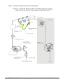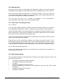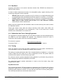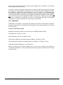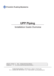
1
Forecourt Equipment Federation …The leading association for equipment manufacturers and their servicing divisions, serving the UK retail petroleum market… Code of Practice Design, Installation, Commissioning, Operation and Maintenance of Stage II Vapour Recovery Systems Issue 1.3 May 2009 FEF (Forecourt Equipment Federation), PO Box 35084, London NW1 4XE Tel: +44 (0) 20 7935 8532 Fax: +44 (0) 700 606 5950 Email: [email protected] Website: www.fef.org.uk The Forecourt Equipment Federation (FEF) is the representative body for equipment manufacturers, and their service divisions, serving the UK retail fuel delivery market. It provides a forum for the industry to share and exchange information on developments in the fuel delivery process and aims to be an authoritative voice on industry issues. This document is published by the FEF who gratefully acknowledge contributions to this Code of Practice (COP) by its members and specifically: Mike Jennings (Editor) Bryan Fotheringham Mike Melnyk Anton Martiniussen Dr Terry Rogers The information contained in this COP is provided as guidance only and while every reasonable care has been taken to ensure accuracy of its contents, the FEF cannot accept any responsibility for any action taken, or not taken, based on the contents. Furthermore, the FEF shall not be liable to any person for any loss or damage that may arise from the use of any material contained herein. In creating this COP the FEF acknowledge documents referenced in the Bibliography. Further copies in pdf format can be obtained from the FEF and its members. Copyright 2006 Forecourt Equipment Federation (FEF). All rights reserved. No part of this COP may be reproduced by any means without the written permission of the publisher. FEF (Forecourt Equipment Federation) PO Box 35084, London NW1 4XE Tel: +44 (0) 20 7935 8532 Fax: +44 (0) 700 606 5950 Email: [email protected] Website: www.fef.org.uk FEF Stage II VR COP Page 2 of 33 Issue 1.3 - 29/06/2009 1 INDEX 1 INDEX ....................................................................................................................... 3 1.1 Index to figures................................................................................................... 4 2 FOREWORD ............................................................................................................. 5 3 BIBLIOGRAPHY........................................................................................................ 6 4 DEFINITIONS............................................................................................................ 7 5 INTRODUCTION ..................................................................................................... 10 6 PERFORMANCE REQUIREMENTS AND CERTIFICATION ................................. 11 6.1 Explosion Safety .............................................................................................. 11 6.1.1 New Equipment......................................................................................... 11 6.1.2 ATEX Certified Dispensers Retrofitted with Vapour Recovery ................. 11 6.1.3 BS7117: Part 1, or SFA3002 Certified Dispensers Retrofitted with Vapour Recovery ................................................................................................................. 11 6.2 Metrology (Weights and Measures) Certification ............................................. 11 6.3 Machinery Directive.......................................................................................... 12 6.4 Electro Magnetic Compatibility (EMC) Directive .............................................. 12 6.5 VR Systems Efficiency and Operation Approvals ............................................ 12 7 CERTIFICATION, MARKING AND LABELLING ..................................................... 13 7.1 7.2 7.3 8 Efficiency .......................................................................................................... 13 Metrology ......................................................................................................... 13 Safety ............................................................................................................... 13 TYPES OF VR SYSTEMS ...................................................................................... 14 8.1 8.2 8.3 9 Active Systems................................................................................................. 14 Automatic Monitoring Systems......................................................................... 14 Other Technology............................................................................................. 15 TRAINING ............................................................................................................... 16 10 ON SITE WORK .................................................................................................. 17 10.1 Pipe-work Installation ....................................................................................... 17 10.1.1 Pipe Materials ........................................................................................... 18 10.1.2 Pipe Length ............................................................................................... 18 10.1.3 Pipe Diameter ........................................................................................... 18 10.1.4 Rate of Fall................................................................................................ 18 10.1.5 Liquid Traps .............................................................................................. 18 10.1.6 Grade Changes......................................................................................... 19 10.1.7 Installation of a Vapour Pipework Pressure Relief Point........................... 19 10.1.8 Work On Site............................................................................................. 19 10.2 Vapour Line Connections To Dispenser .......................................................... 20 10.2.1 Accident Damage...................................................................................... 20 10.2.2 Vapour Return Line Isolation .................................................................... 20 10.3 Line testing ....................................................................................................... 21 10.4 Existing Sites.................................................................................................... 22 10.5 Tests Prior To Putting Into Use ........................................................................ 22 10.5.1 Retrofit ...................................................................................................... 22 10.5.2 New and Retrofit Dispensers .................................................................... 22 10.6 Site Documentation .......................................................................................... 22 FEF Stage II VR COP Page 3 of 33 Issue 1.3 - 29/06/2009 11 DISPOSAL OF DISPLACED PARTS .................................................................. 24 12 INITIAL AND IN-SERVICE VERIFICATION ........................................................ 25 12.1 12.2 12.3 12.4 12.5 Test Equipment ................................................................................................ 25 Gas Meter ........................................................................................................ 26 Calibration And Factor Setting Equipment ....................................................... 26 Testing ............................................................................................................. 26 Calibration ........................................................................................................ 27 13 MAINTENANCE AND REPAIR............................................................................ 28 14 APPENDIX 1 - COMPLIANCE CERTIFICATES.................................................. 29 14.1 15 Introduction ...................................................................................................... 29 APPENDIX 2 - ETHANOL AND ALTERNATIVE FUELS..................................... 33 15.1 15.2 1.1 Low Blend Ethanol Fuels Within The Scope Of EN228 ................................... 33 High Blend Ethanol Fuels................................................................................. 33 Index to Figures Figure 1 Figure 2 Figure 3 Figure 4 Example Of Active Vapour Recovery System Under Dispenser Shear Valve Tank To Dispenser Pipe-Work On-Site Efficiency Test Connections FEF Stage II VR COP Page 4 of 33 9 20 21 25 Issue 1.3 - 29/06/2009 2 FOREWORD This Code Of Practice has been compiled by the FEF to provide guidance that is consistent and informative. This has been achieved by incorporating the requirements of the European standards referenced in Process Guidance Note 1/14(06) containing guidance on Statutory Instrument 2006 No. 2311 and, other codes of practice relating to Stage II Vapour Recovery. In addition to operation and efficiency, the text highlights the following areas of compliance with particular reference to the modification of existing equipment: Continued certification of modified equipment: ATEX rules when applied to new or existing equipment to provide clear guidance to those considering the modification of equipment for use in flammable atmospheres particularly when changing the design of equipment not designed by them and where they do not have access to the manufacturer’s specifications used in original certification. Quality of work carried out: The FEF have highlighted responsibilities under ATEX and DSEAR for those engaged in modifications to be adequately qualified - Annex IV and related processes. CE Marking: Modification of CE marked products requires specific procedures to be observed. Work practices used in Europe that may not be applicable in the UK: We have highlighted the generic rules for work on UK service stations. This Code of Practice was produced in consultation with the Health and Safety Executive. The Health and Safety Executive believes that the contents of this code represent good practice in the industry and commends its use. FEF Stage II VR COP Page 5 of 33 Issue 1.3 - 29/06/2009 3 BIBLIOGRAPHY Statutory Instrument 2006 No.2311. The Pollution and Control (England & Wales) (Amendment) (England) Regulations coming into force 1st October 2006. APEA/IP Blue Book, Design, Construction, Modification, Modification and Decommissioning of Filling Stations, and Section 9.7.3, 2nd Edition, 2005, Published jointly by the APEA and Energy Institute. Commonly known as the Blue Book. ATEX Guidelines (Second Edition), Guidelines on the application of Council Directive 94/9/EC of 23 March 1994 on the approximation of the laws of the Member States concerning equipment and protective systems intended for use in potentially explosive atmospheres, European Commission, Available at www.europa.eu.int/comm/enterprise/atex/guide/index.htm. ATEX Product Directive, Directive 94/9/EC of the European Parliament and the Council of 23 March 1994 on the approximation of the laws of the Member States concerning equipment and protective systems intended for use in potentially explosive atmospheres, Official Journal of the European Communities, L 100, 19.04.94. Equipment and Protective Systems Intended for use in Potentially Explosive Atmospheres SI No. 192 1996. This Statutory Instrument is the enabling legislation for the ATEX directive in the UK. Available from www.opsi.gov.uk. BEAMA / AEMT Ex Code of Practice Number 300. Repair and overhaul of Ex electrical apparatus. ISBN 0 901639 12 5 (BEAMA) or ISBN 0 9509409 17 (AEMT). BS 7117: Part 1 Metering pumps and dispensers to be installed at filling stations and used to dispense liquid fuel Part 1. Specification for construction, BSI, London. BS IEC 60079 19, Repair and overhaul for apparatus used in explosive gas atmospheres, BSI, London. CECOD, 2005, Proposal for Test Procedures for Vapour Recovery Systems and Vapour Recovery Monitoring Devices in Metering Petrol Pumps/Dispensers and Dispersed Unit Delivery Systems on Filling Stations (D191), Issue 10, CECOD, Paris (Restricted to CECOD Members only). DSEAR Regulations, The Dangerous Substances and Explosive Atmospheres Regulations 2002, SI 2002 No 2776. EN 13617 1 Petrol filling stations – Parts 1,2and3: Safety requirements for construction and performance of metering pumps, dispensers and remote pumping units etal, BSI, London. Guidelines For The Design and Operation of Gasoline Vapour Emission Controls (The IP – March 1992) – Section 11. HSE guide to refurbished dispensers LAC Number: 65/8 – December 1997. PAS 022: Specification for Construction of Vapour Recovery systems installed in petrol metering pumps and dispensers, BSI, London. Process guidance note PGN 1/14 (06), Unloading of Petrol into Storage at Petrol Stations – DEFRA. SFA3002: 1971, BASEEFA Standard, HSE, EECS/BASEEFA, Buxton. PETEL LAC Number 65-30: November 2000 - available from the HSE. VDI 4205 Measurement and test methods for the assessment of Vapour Recovery systems on filling stations – Verein Deutscher Ingenieure. APEA/IP ‘Guidance On Storage And Dispensing Of High Blend Ethanol Fuels Including E85 At Filling Stations’ 2007. FEF ‘Guidance to Retailers and Maintenance Companies on the Introduction of Low Blend Biofuels to UK Filling Stations’ 2008. FEF Stage II VR COP Page 6 of 33 Issue 1.3 - 29/06/2009 4 DEFINITIONS Automatic VR Monitor Coaxial Hose Competent Person Control Electronics for VR Dry-Test Flame Arrestor Flow Control Valve (Proportional Valve) Isolation Valve Liquid Trap Manufacturer Non-Automatic VR monitor Notified Body OEM Pressure-Vacuum Valves Qmax Qmin FEF Stage II VR COP An automatic monitoring system that automatically detects faults in the functioning of the petrol Vapour Recovery system including the automatic monitoring system itself and indicates faults to the site operator. A hose within a hose where the inner hose is used to carry the vapour. Qualified to identify risks within a scope of work and apply appropriate work methods and tools. For Stage II VR this would include compliance with The Electricity at Work Regulations 1989 and the UKPIA Forecourt Contractor Safety Passport Scheme or equivalent. Typically additional to the standard dispenser electronics and used to start vapour motors, control the vapour collection rate and generate alarms for monitoring systems. A test performed on site where a gas meter is used to measure air flow back to the tank on a simulated delivery. Used for calibration and checking of the VR system. A device fitted in the vapour path to prevent the passage of flame. A device that controls the flow of vapour (to equate to the flow of petrol). A device that seals a vapour or fuel pipe. The valve may be manually operated or operate automatically. Pipe work or fittings that permit the collection and partial retention of condensate or liquid. Person responsible for the design and manufacture of new components, kits or fuelling systems. Used for basic function tests where an annual inspection and test is required. Authorised by an EU Member State to certify equipment and processes as compliant to EU directives and standards. Original Equipment Manufacturer – in this document ‘OEM’ often refers to the manufacturer of an existing installed dispenser or other certified component. A device fitted to the tank vent(s) that prevents the escape of vapour under normal operation but opens at a pre-set pressure and vacuum difference. The maximum flow rate. The minimum flow rate Page 7 of 33 Issue 1.3 - 29/06/2009 Safe-Break Fuel and Vapour Coupling Shear Valve Splitter Stage 1b Vapour Recovery Stage II Vapour Recovery V/P Ratio (Percentage) Vapour Pump Vapour Recovery Nozzle High Blend Ethanol Fuel (HBEF) Low Blend Biofuel [Ethanol Fuels] (LBBF) ‘K’ Factor FEF Stage II VR COP Device to minimise fuel spillage and to stop fuel flow achieved by separation between nozzle and metering pump or dispenser within a defined range of forces. A device fitted at the dispenser base that seals the vapour return pipe in the event of the dispenser being severely damaged. An adaptor for separating the fuel and vapour flow from the coaxial hose into separate pipes. Petrol vapour is displaced from Petrol Station storage tanks and returned to the distribution terminal using the fuel delivery tanker. Includes petrol station vent pipes, and related systems. Petrol vapour is recovered from the vehicle tank and returned to the petrol Station storage tank for collection by Stage I b systems. Alternative systems may return the vapour to other tanks or recovery systems. Recovered Vapour Volume in Litres divided by the Delivered Petrol Volume in Litres all multiplied by 100. A device, typically driven by a motor, for drawing vapour from vehicle tank. Similar to normal petrol nozzle but including an annulus that collects vapour and passes it to a collection system typically via integral flow enable valve. A blend of ethanol and petroleum-spirit with the ethanol constituent ranging generally between approximately 30% and 90% (definition taken from APEA/IP guidance). Unleaded petrol products with a bioethanol content which are in conformance with EN228: 2004. These include a 5% (nominal) ethanol blend often referred to as E5). A correction factor specific to a particular vapour recovery system design to take into account the performance when tested with air compared to the performance when recovering petroleum vapour. Page 8 of 33 Issue 1.3 - 29/06/2009 Figure 1 Example of Active Vapour Recovery System FEF Stage II VR COP Page 9 of 33 Issue 1.3 - 29/06/2009 5 INTRODUCTION Throughout this COP Stage II Vapour Recovery is referred to as Stage II VR and may include any related technologies including Vapour Recovery Monitoring and vapour recycling systems. Stage II Vapour Recovery is in addition to existing, and unchanged, Stage 1b requirements in the UK. This COP is provided by the FEF as a technical resource for those engaged in the supply and implementation of Vapour Recovery in the UK. This COP is exclusively concerned with Vapour Recovery systems for Petrol; extended requirements for E85 and other petrol variants will be covered in Appendix 2 to this document. On behalf of the UK Government, DEFRA have issued a Process Guidance Note that requires the use of existing best available technology (BAT), ie technology that is approved by a recognised European VR testing laboratory (EU or EFTA). Recognising that the UK market has generally not implemented Stage II VR or, where it has, the installed equipment may not meet current requirements, it is the purpose of this COP to provide implementation guidelines based on existing standards, guidance notes and reports from the UK and Europe. The in-service testing requirements covering Stage II VR require calibration and testing prior to commissioning. The efficiency of the Vapour Recovery system shall be tested at least once every three years where an automatic monitoring system is in place or once every year in other cases. (DEFRA Process Guidance Note 1/14(06), Table 2). The FEF has drawn heavily on European experience, including the German standards referenced by DEFRA. The FEF also recognises that other technology not referred to in this document may be employed to meet the VR regulations but that these technologies will need to be installed and maintained meeting the requirements herein. FEF Stage II VR COP Page 10 of 33 Issue 1.3 - 29/06/2009 6 PERFORMANCE REQUIREMENTS AND CERTIFICATION 6.1 6.1.1 Explosion Safety New Equipment Dispensers operate within potentially explosive atmospheres, and new dispensers must be third party certified as being in compliance with the ATEX Directive. The most common approach to demonstrating compliance with the Directive is by certification to EN13617-1. Manufacturers shall note that this standard has/includes requirements for dispensers with Vapour Recovery systems, and any certification to the standard shall be extended, where required, to include an assessment against the relevant clauses. Note that these requirements extend beyond the need to use certified vapour pumps and control valves, and cover such items as mechanical strength of the vapour circuit in order to contain a potential internal explosion. 6.1.2 ATEX Certified Dispensers Retrofitted with Vapour Recovery The introduction of Vapour Recovery into a dispenser may affect the zoning both internal and external to the dispenser and therefore due consideration should be taken including the possibility of a zone 0. Any changes to the external hazardous areas will require revision to the site risk assessment under the DSEAR Regulations. The addition of Vapour Recovery systems to existing equipment is a ‘substantial modification’, and the ATEX Product Directive is applicable to the resultant modified equipment. (APEA/IP Blue Book Section 9.7.3). The modified equipment design should be certified by a Notified Body as complying with the requirements of the ATEX Product Directive. The organisation performing the modifications shall operate a quality management system approved to the requirements of Annex IV of the ATEX Product Directive. (See also Schedule 7 of the ATEX Regulations). 6.1.3 BS7117: Part 1, or SFA3002 Certified Dispensers Retrofitted with Vapour Recovery The kit (the VR components) must be ATEX certified by an ATEX Notified Body. The dispenser design with the proposed modification should be assessed by an ATEX Notified Body as being in compliance with its original standards (or the ATEX directive) when modified with VR. 6.2 Metrology (Weights and Measures) Certification A valid metrological (Weights and Measures) certificate is required for the modified dispenser and connected payment systems. This may be a valid UK National Weights and Measures certificate from NWML, or, after October 2006, may be a certificate demonstrating compliance with the Measuring Instruments Directive. Certification would take account that the addition of a Vapour Recovery system, with or without monitoring, to a dispenser, could potentially be detrimental to the dispenser metrological functionality and security. Certification will confirm that the VR system does not interfere with fuel measurement accuracy, gas separation performance, POS communications or immunity of the calculator electronics to adverse power supply conditions or electromagnetic interference. FEF Stage II VR COP Page 11 of 33 Issue 1.3 - 29/06/2009 6.3 Machinery Directive The Machinery Directive applies to dispensers produced after 1993. The manufacturer shall create a Technical Construction File demonstrating conformance with the Directive for CE marked dispensers and it is recommended that a similar approach be adopted for earlier dispensers. 6.4 Electro Magnetic Compatibility (EMC) Directive It should be noted that the EMC Directive applies to dispensers produced after 1989. Vapour Recovery dispensers, whether new, or retrofitted, require the dispenser to be compliant with the requirements of the Directive. This is a particular consideration where additional electronics are added to the dispenser in order to control the Vapour Recovery system. The manufacturer shall create a Technical Construction File demonstrating conformance with the Directive or the VR modification kit should be assessed by an EMC laboratory. Similarly, equipment remote from the dispensers used within monitoring systems shall also be compliant with the requirements of the EMC Directive. Re-testing of the complete dispenser is not required provided the complete VR system is compliant. 6.5 VR Systems Efficiency and Operation Approvals The UK requirement for a minimum Hydrocarbon recovery efficiency of 85% can be met using equipment designed in such a way that if the recovered volume is at least 95% and not greater than 105% of the delivered fuel volume then compliance is implied. VR Stage II equipment is approved as a system based around the nozzle interface to a “selection” of typical vehicles. No component in the dispenser VR system should be modified or substituted without confirmation from the OEM that the system is still within certification scope. Systems shall have a certificate related to recovery efficiency from a recognised body within EU or EEA. For example, TUV (Germany), SP (Sweden). Such certificates list a combination of components that may constitute a system. This details the component manufacturer and component type/model identification. Typically it lists a nozzle type, a hose type, a vapour pump type, a control valve or other flow regulator, any control electronics and, optionally, monitoring system components that may influence the vapour collection efficiency of the system. It is recognised that UK regulations and guidance might not require detailed features listed within a national certificate or within regulations from another European country. For example, the time for which a dispenser may continue to make fuel deliveries whilst its Vapour Recovery system is not operational before the dispenser must be repaired or put out of service may be different. The Vapour Recovery system manufacturer shall document such deviations from the certificate and make this document available. Such deviations shall not extend to substituting one component listed on the system certificate with another. FEF Stage II VR COP Page 12 of 33 Issue 1.3 - 29/06/2009 7 7.1 CERTIFICATION, MARKING AND LABELLING Efficiency Dispensers fitted with VR shall be marked with a service label that includes: a. b. c. Name of supplier of the VR system. Base efficiency approval reference e.g. <TüV><Certificate number>. Calibration “K” factor of the pump and system for active systems. Typically this label will be fitted adjacent to the VR calibration feature in the electronics enclosure. 7.2 Metrology Adding VR may have changed the W&M approval to another OEM variant – if so then the Weight and Measures approval plate number must be changed. 7.3 Safety Where a dispenser modified with the addition of a Vapour Recovery system is still in conformance with the original dispenser ATEX certificate number and the original Weights and Measures certificate number, and is modified by the original manufacturer, the dispenser should be simply labelled: • This dispenser was modified by <company name> in <month/year>. In all other circumstances new labelling shall be included in close proximity to the original type plate. This shall identify that: • • • • The dispenser has been modified by the addition of a Vapour Recovery system. The name of the company performing the modification. Whether the original safety certificate number(s) remain valid or not. New certificate numbers related to the modified equipment. FEF Stage II VR COP Page 13 of 33 Issue 1.3 - 29/06/2009 8 TYPES OF VR SYSTEMS This section is intended as an overview of the more common VR systems available. 8.1 Active Systems Vapour is actively sucked from the vehicle tank using a vapour pump. The actual volume recovered by the pump is regulated typically by changing pump speed or using proportional valves. The nozzle does not seal to the vehicle but uses an approved efficiency system based on nozzles verified with a range of vehicles. 8.2 Automatic Monitoring Systems The minimum requirement for an automatic monitoring system is that it can detect the flow of vapour at the required flow rate within the Vapour Recovery circuit of the dispenser. Automatic monitoring systems should automatically detect faults in the proper functioning of the petrol Vapour Recovery system including the automatic monitoring system itself and indicate faults to the site operator. A fault should be deemed to be present where continuous monitoring during filling of vehicle petrol tanks indicates that the vapour to petrol (V/P) ratio averaged over the duration of filling has fallen below 85% or has exceeded 115% for ten consecutive filling operations. This only applies to filling operations of at least 20 seconds duration and where the rate of petrol dispensed reaches at least 25 litres per minute. If the fault is not rectified within 1 (one) week the system will automatically prevent further transactions. Basic forms of Vapour Recovery fault detection also exist. These may simply turn on an error indicator in the event of electronics controlling the Vapour Recovery system not seeing information from the dispenser main calculator, or not seeing the Vapour Recovery motor turn on during a petrol sale transaction. Another is a handheld harmonica type hand held functionality checking device. These are not regarded as “Automatic Monitoring systems”. The implementation of Stage II VR in the UK requires that systems installed without Automatic Monitoring systems are manually checked on a regular basis. Performance and functionality is defined in PGN1/14 (06) or its potential successor. Various types of monitoring systems exist, with optional features. Generally the more sophisticated the monitoring system, the less manual checking and recording required. A basic monitoring system might simply turn on an error lamp on the dispenser in the event of detecting a problem with vapour flow. Note that such systems will still require operators to regularly check there are no error indications, and to ensure that the equipment is repaired within seven days. Monitoring systems may incorporate a kiosk control unit that communicates with the Vapour Recovery systems in the dispensers, and provide a single point at which the status of all dispensers can be seen. Such systems may provide a continuous log that records dates and times on which Vapour Recovery systems were working correctly, and when there were faults, thus reducing the need for any manual logbooks. FEF Stage II VR COP Page 14 of 33 Issue 1.3 - 29/06/2009 More sophisticated monitoring systems may provide communications. Such systems may allow a company with several sites to monitor the Vapour Recovery status of all their sites remotely, possibly via the internet. Such systems may also automatically send alerts to a service/repair company when a Vapour Recovery system failure is detected, ensuring that the equipment is repaired within the seven day period. 8.3 Other Technology Systems may exist that collect, reformulate or absorb petrol vapour both within a metering pump and external to it. Where dispenser based, the implementation guidance in this COP applies. Balanced VR (with rubber bellows) systems are rarely used today and have effectively been superseded by active systems, the FEF would not recommend the use of these systems and they are therefore not covered in this document. FEF Stage II VR COP Page 15 of 33 Issue 1.3 - 29/06/2009 9 TRAINING Installers of Stage II VR equipment should be trained by the OEM in the installation procedures and requirements for safe use. This is so that any Essential Health and Safety Requirements (EHSR) relating to the dispenser design or installation are covered in detail. It is critical that installers have recorded training and documentation on the systems they are installing. Where the OEM is no longer trading these design records may not be available or reliable and this should be included in the risk assessment prior to commitment to modify. In order to be regarded as Stage II VR Competent an engineer will need to be an existing Competent Person (Service and maintenance of Fuel Dispensers and systems) with supplementary Stage II VR training. The training must be OEM qualified and include receiving the necessary drawings and instructions relevant to the pumps/dispensers that are to be installed, tested or calibrated. Any person working on VR II systems will need to demonstrate competence, this may be through a recognised training scheme ie; the UKPIA Forecourt Contractor Safety Passport Scheme. All work on site will require a “Methods Statement” and “Risk Assessment as required under DSEAR regulations. Training topics should include: 1. 2. 3. 4. 5. 6. 7. Overview of the system and components used, i.e. how the Stage II VR system works. Critical zones and barriers associated with the original pump approvals. The use of the correct approved components within the Stage II VR system so that the approvals are not compromised in any way during installation or maintenance. What components can be maintained, and who would maintain these. Identification of components that need to be replaced and not tampered or altered in any way during maintenance of the system. How to test and calibrate the Stage II VR system in accordance with the manufacturer’s recommendations. A detailed explanation of the VR test equipment. The training of Maintenance and Service technicians should include an appreciation of the various EEX protection schemes used in VR systems and how to ensure continued compliance with certification. Technicians involved in the maintenance of ATEX approved components must be made aware of the need to use spare parts that are compliant with the original part specification in every way – if these are not supplied by the OEM then they should be approved by the OEM. FEF Stage II VR COP Page 16 of 33 Issue 1.3 - 29/06/2009 10 ON SITE WORK Installing new dispensers should not pose any major problems for installers/contractors, as these pumps will be approved to the ATEX legislation. The installation instructions will be delivered with the pump and should be clear and concise as they form part of the pump approvals. Retrofits shall be made in accordance with instructions supplied for the retrofit kit. No retrofit shall take place without such instructions. UK legislation, approved codes of practice and guidance on safe working shall be observed at all times. Beyond normal forecourt working considerations, the following shall be taken into account: Retrofits will normally require the exchange of hoses and nozzles, and the exchange of couplings in the dispenser to which the hoses connect. Therefore loss of fuel from the dispenser hydraulic circuits is anticipated. Care shall be taken to capture as much of this fuel as practicable, and avoid leakage onto the forecourt. The action of opening the fuel circuit or delivering fuel into a test can create a potentially explosive atmosphere creating a Zone 1 potential hazard both within the dispenser hydraulic cabinet and extending to a radius of 3.6 metres and 1.2 meters high. All relevant precautions must therefore be taken, including isolation of all power to the dispenser being worked upon, this may include closing other dispensers within the working area and possibly the whole forecourt. All test equipment used must be suitable for the hazard zone in which it is used. This will be determined when the scope of work risk assessment is completed. If the site has been partially operating with Stage II vapour recovery, for example, during a staged retrofit of a site, there is a risk that the underground vapour pipework, the ullage space of storage tanks, and the tank vent system may be under pressure. This is a risk particularly associated with sites where the storage tank vent system is fitted with a PV valve. In these circumstances, prior to any work taking place which requires opening of the vapour pipework or the tank ullage space, any dispensers operating with vapour recovery shall be disabled, and the pressure shall be relieved at the storage tank vent system. Where no specific device is incorporated into the tank vent system to perform this, any equipment used shall be specifically designed to perform this operation and shall release the vapour at a high level through a flame arrester, preferably at a point in close proximity to the existing tank vent outlet. When working on vapour pipework within dispensers, a shut-off valve(s) must be closed to prevent emissions of vapour into the work area. If such a valve(s) is not present, all fuelling from the related tank or tanks must be prevented by closing the linked dispensers, and any pressure in the underground pipework must be relieved. 10.1 Pipe-work Installation General Vapour return piping from the pumps/dispensers may be arranged individually or shared. An individual piping configuration returns the vapour to the petrol tank from which the fuel was supplied, this is normally only done on small sites with one petrol grade per pump. Shared piping configurations connect all the vapour return pipes from the pumps/dispensers and connects them via a single pipe to a single tank. In this FEF Stage II VR COP Page 17 of 33 Issue 1.3 - 29/06/2009 configuration all the petrol tanks must have a connecting manifold, which allows the vapours to flow freely between them, so that the tank vapour/fuel volumes can be balanced. This is the normal configuration on multi-grade pumps mainly for cost and efficiency reasons however in the presence of connected diesel tanks see section 10.1.6: Grade Changes. It is known that some of the vapour in the return pipes will condense into liquid, for this reason, consideration must be given to the materials, fall, liquid traps etc and essentially the installation and construction standards are the same as for fuel pipes and Stage 1B piping. See IP/APEA Blue Book for guidance. 10.1.1 Pipe Materials Vapour return pipes must be made of materials rated for petrol. The IP and APEA ‘Blue Book’ section 8.5.3 gives appropriate guidance. 10.1.2 Pipe Length As with the fuel pipes, vapour return pipes should be efficiently laid out to be as short as possible. 10.1.3 Pipe Diameter The pipe diameter must be chosen to ensure the appropriate volume of vapour can be accommodated with minimum back pressure. The normal diameter of the vapour return riser pipe (the pipe which comes out from the pump/dispenser (see Fig. 2) is 25mm (1”). This is then normally connected to a 50mm (2”) pipe. This may run all the way back to the tanks, or in the case of shared piping configuration, may be connected, along with other 50mm pipes from different islands to a larger pipe (75mm) 3” and then back to the tanks. Piping which is accommodating the vapour from more than 8 pumps vapour pump should be 75mm and the manifold piping on the tanks should be 75mm. 10.1.4 Rate of Fall The site layout will normally dictate the fall of the fuel and vapour return pipes, which will be essentially the same. It is important that any liquid in the vapour return pipes flows back into the tank, so the minimum rate of fall should be 1:100, however 1:50 is more normal. 10.1.5 Liquid Traps The vapour return pipes must be as unobstructed as possible, it is important that the pipes are laid so that no liquid traps occur, a liquid trap is where the pipe has a low point, where liquid would gather and partially or fully block the vapour return path. It is important therefore that the vapour return pipes are laid with an even fall and on a firm base, so that later subsidence does not cause liquid traps. FEF Stage II VR COP Page 18 of 33 Issue 1.3 - 29/06/2009 10.1.6 Grade Changes When designing the layout of the vapour returns pipe-work, consideration should be given to the possibility that the fuel grades stored in the tanks may change over time. Careful consideration at this stage could save time and cost in later years. Consideration must be given to tanks previously used for petrol but converted to diesel storage. These may have existing vapour manifold connections to tanks currently used for petrol; this may result in petrol vapour being present in diesel tanks. a. Ensure that the diesel tank fittings and connected systems are certified for petrol; check that these have not been down-graded since conversion to diesel. b. Check the retailer has confirmed that the presence of petrol vapour does not degrade the stored diesel properties. c. Consider isolating the Stage II Vapour Recovery pipes from the diesel tanks. (Recommended). d. Refer to HSE PETEL 65/30 (Tank manifolding concerns related to Stage Ib) for further advice. 10.1.7 Installation of a Vapour Pipework Pressure Relief Point The introduction of Stage II vapour recovery systems can result in the vapour pipework and tank ullage spaces becoming pressurized, in particular if the tank vent system is fitted with a PV valve. This can bring risks during any maintenance work that involves opening vapour pipework or vapour containment. Hence it is strongly recommended that a device to allow relieving of the pressure in the vapour circuit should be permanently fitted at the storage tank vent system. The vapour release point shall be at a high level, and the outlet shall be fitted with a flame arrester. 10.1.8 Work On Site It is often a pre-requisite that contractors installing the Stage II VR pipe-work will participate in the UKPIA “Passport to Work” scheme. As well as specific duties to control risk arising from dangerous substances, under DSEAR, there is also responsibility under the Management of Health and Safety Regulations 1999. It is the contractor's responsibility to comply with these regulations. This is explained in detail in “Design, Construction, Modification, Maintenance and Decommissioning of Filling Stations – 2nd Edition, March 2005 (APEA/IP Blue Book) – pages 35 – 36. When considering likely hazards, full reference should be made to the following: • • • • • • • N.B. Hazardous area drawings pertaining to the Petrol Filling Station, clearly showing the various zones that exist. Additional hazardous areas created by the work proposed. Defined safe working areas out side hazard zones. Underground services and pipe-work. Existing site procedures. Relevant legislation and guidance (whether Local or European). Any other industry Codes of Practice. DSEAR can be seen to be an expansion of the general duties to manage risks under the “Management of Health and Safety at Work Regulations 1999 and specific duties to control risks arising from Dangerous Substances. FEF Stage II VR COP Page 19 of 33 Issue 1.3 - 29/06/2009 10.2 Vapour Line Connections To Dispenser 10.2.1 Accident Damage The APEA/IP Blue Book recommends the fitment of a shear valve at the connection between the dispenser base and sub-frame. This device is normally a double-poppetted shut-off valve triggered at impact. Figure 2 Under Dispenser Shear Valve Shear valves shall comply with the requirements of EN13617 part3. 10.2.2 Vapour Return Line Isolation Provision shall be made that, during maintenance and repair to the VR system, the vapour pipe to the tank must be sealed thus preventing vapour escape from the storage tank to the work areas and also preventing any ignition source in the work area from entering the pipe-tank system. This requirement can be met using an isolation valve (preferred), or a flame arrestor with a maintenance sealing cap used on the tank-side of the point where disassembly has taken place. FEF Stage II VR COP Page 20 of 33 Issue 1.3 - 29/06/2009 The shear valve must crack on impact before any other pipes or fittings are compromised so it is vital that mechanical fixing to BOTH the dispenser and sub frame is designed and verified by physical test. A test report should be kept in the Dispenser Technical Construction file. The above components are the minimum that the installer will require for an approved installation. Additional components can be used (if approved for working in Hazardous areas), if required by the customer. 10.3 Line testing Underground pipe-work should be tested in accordance with The APEA/IP Blue Book section 8. Figure 3 Tank To Dispenser Pipe-Work Dispenser e d Forecourt Level Island c b a VAPOUR RETURN TANK a. b. c. d. e. Vapour Return Pipe Tank Coupling Under Pump Bends Internal Vapour Pipe Shear Valve Once the above pipe-work has been installed as per the UK recommendations, then the pipe-work (and associated connections) is ready for testing. The pipe-work is tested under air pressure (absolute minimum of 0.7bar for 30 minutes) to make sure that the pipe-work and fittings are leak free prior to back filling the pipework. NB – The minimum pressure used in other EU markets is up to 5Bar. On passing the test the contractor will issue a Test Certificate as required for the site documentation. Once the Stage II VR pipe-work has been completely installed the contractor will then provide the site with a “Completion Certificate”. FEF Stage II VR COP Page 21 of 33 Issue 1.3 - 29/06/2009 10.4 Existing Sites Some sites may or may not have Stage II VR pipe-work installed. If not, then the same installation process applies, as discussed above when installing pipe-work for new sites. Some sites may already have pipe-work, i.e. ‘Stage II VR ready’. If this is the case then it is recommended that the installers review the condition of the installed pipe-work and test as above. Complete and issue test certificate. The next step will then be to update the dispenser to the manufacturer’s recommendations and connect up to the installed pipe-work. 10.5 Tests Prior To Putting Into Use 10.5.1 Retrofit The earth path between dispenser chassis and nozzle shall be tested prior to operation of the dispenser per EN13617-1 table 3 – Resistance nozzle spout to earth (terminal). Conduct electrical tests on the whole dispenser to confirm that electrical safety has not been compromised. These tests are defined in the APEA/IP Blue Book and are a repeat of the normal annual insulation and resistance tests. Confirm required dispenser operation before checking the VR system. Ensure fuel flow rates are as required on petrol grades. Pressure test the VR connections between the nozzles and vapour pump. This is performed by hanging-up all nozzles in the nozzle-boots and applying a 700 mb vacuum to the disconnected inlet pipe at the vapour pump. Use a ball valve and pressure meter in the test pressure source to isolate the pressure source and check for pressure decay. 10.5.2 New and Retrofit Dispensers Stage II VR efficiency test performed to manufacturers’ instructions and completion of the Compliance Certificate. 10.6 Site Documentation The site logbook should be completed with the details of the Vapour Recovery retrofit. This shall include a record of: • • • • • • • The person making the retrofit modification. The company making the modification. The date. Dispenser numbers and serial numbers. A record identifying the retrofit kit, by manufacturer, type, and any serial number information. Underground pipe-work test report. Compliance certificate. FEF Stage II VR COP Page 22 of 33 Issue 1.3 - 29/06/2009 The site owner should be given documentation relevant to the VR system: • • • • • Pipe-work diagrams to tanks. User manual. Certification. Calibration results. Completed Compliance checklist. FEF Stage II VR COP Page 23 of 33 Issue 1.3 - 29/06/2009 11 DISPOSAL OF DISPLACED PARTS Vapour Recovery retrofits lead to a significant number of parts being displaced from dispensers. These would include as a minimum, non-Vapour Recovery hoses, nozzles and breakaway couplings. Recognising the potential quantity of displaced parts provision must be made for the safe disposal or safe recovery of the components for use as spare parts. A disposal plan shall be determined and implemented on behalf of the equipment owner. FEF Stage II VR COP Page 24 of 33 Issue 1.3 - 29/06/2009 12 INITIAL AND IN-SERVICE VERIFICATION This section describes the test equipment and process for VR Stage II efficiency measurement. 12.1 Test Equipment All electronic test and calibration equipment used on Petrol Forecourts must be approved for the hazard zone in which it will be used or placed in a non-hazardous area. Figure 4 On-Site Efficiency Test Connections Typical on-site test arrangement in Fig 4. 1. 2. 3. 4. 5. 6. 7. 8. 9. Hand held terminal provided by the VR system supplier. Gas (vapour) flow-rate meter. Dispenser nozzle and hose with meter adapter. The nozzle may have an integral proportional valve negating items 5 and 6. Dispenser. VR electronics – typically an add-on module connected to the host dispenser. Proportional gas flow valve. Vacuum pump (when this is variable speed the proportional valve is not used). Vacuum pump motor. Underground storage tank. FEF Stage II VR COP Page 25 of 33 Issue 1.3 - 29/06/2009 12.2 Gas Meter Accuracy information in this section has been derived from VDI4205 as referenced in DEFRA PGN1/14(06). In order to obtain measurement results of an acceptable quality, regular checking of the measuring equipment used is essential. • • • Bellows Type should be checked every 6 months by a recognised testing body to domestic gas meter standards where these equal to or exceed +/- 2% at 40lm. Impeller Types should be checked every 2 months by a recognised testing body to domestic gas meter standards where these equal to or exceed +/- 1% at 40lm. Other types of meter should meet at least +/-1% with calibration intervals advised by the meter manufacturer. Meters shall be marked with last calibration date and test authority and shall be within the calibration period. These gas meters must meet the above accuracy limits when used within the temperature range specified by the manufacturer, if this is not known then a meter should not be used below 5°C or above 25°C. 12.3 Calibration And Factor Setting Equipment This equipment is typically supplied by the VR system supplier and must be approved by the OEM for use with supplied VR systems. The equipment should be used in conjunction with operation and use instructions supplied. For electronic systems: Correction Factor = Vapour Recovery Rate (Air) Vapour Recovery Rate (HC – Vapour) 12.4 Testing Once the retrofit to the pump has been completed to the VR system manufacturer’s recommendations, then the complete VR system shall be tested. The testing is usually performed under “Dry” simulated delivery conditions, i.e. the pump nozzle is lifted from the holster but no fuel is dispensed, but the VR system works as normal and the system is monitored by a gas meter. For electronic control systems adjustment and calibration is performed using electronic factor setting using equipment supplied by the OEM. For mechanical control systems adjustment is made at the fuel nozzle using tools supplied by the OEM. Dry Measurements This is where the Stage II VR test equipment is attached to the VR nozzle and no fuel is dispensed. However, air is sucked back to the tank through the nozzle via a calibration metering system defined in section 12.1 that will verify the rate of recovery taking place. This recovery rate will have a correction factor built-in. FEF Stage II VR COP Page 26 of 33 Issue 1.3 - 29/06/2009 Prior to Dry measurement tests a vapour path leakage test is required in accordance with manufacturer’s instructions. In order to meet the minimum requirement of all (active Vapour Recovery) pump types the following recommendations should be used: That Qmax shall be adjusted to match the maximum vapour flow rate provided by the VR system. The manufacturer’s instructions for measuring fuel flow and vapour flow rates shall be used. Qmax for Stage II VR is as specified in the efficiency type approval certificate available from the OEM, or less if limited by the actual dispenser possible fuel flow rate. Note that, the maximum Qmax for a dispenser is specified as part of its Metrology approvals and typically recorded on the Approvals Plate, this must never be exceeded. 12.5 Calibration Calibration of the Stage II VR system will make sure that the correct levels of vapours are being recovered, as specified and implemented by the UK regulations and set out below for clarity. Volume: Petrol Ratio Limits. Reference should be made to most recent issue of DEFRA PGN1/14(06): Type approval V/P 95% to 105%. Initial Calibration on site V/P 95% to 105%. Annual check (Without monitoring system installed) V/P 95% to 105%. Three yearly check (When monitoring system is installed) V/P 95% to 105%. Automatic Monitoring Systems - see section 8.2. When the Stage II VR system passes the test then the installer will complete a “Compliance Certificate” of the complete system and supply the retailer with one copy for site records. FEF Stage II VR COP Page 27 of 33 Issue 1.3 - 29/06/2009 13 MAINTENANCE AND REPAIR Routine service should be carried out by engineers with at least the same level of qualification and training that apply to dispenser maintenance. In addition they should be trained in the special hazards associated with Vapour Recovery. Particular care needs to be taken when working on vapour pipework or storage tanks on sites with Stage II vapour recovery systems, due to the risks of pressurized vapour being present. Prior to any work taking place which requires opening of the vapour pipework or accessing the ullage space of tanks, any dispensers operating with Stage II vapour recovery shall be disabled, and the pressure shall be relieved at the storage tank vent system. Where no specific device is incorporated into the tank vent system to perform this, any equipment used shall be specifically designed to perform this operation and shall release the vapour at a high level through a flame arrester, preferably at a point in close proximity to the existing tank vent outlet. There shall be no access to the area by non-approved personnel and an exclusion of all ignition sources including non-approved tools and equipment. When working on vapour pipework within dispensers, a shut-off valve(s) must be closed to prevent emissions of vapour into the work area. If such a valve(s) is not present, all fuelling from the related tank or tanks must be prevented by closing the linked dispensers, and any pressure in the underground pipework must be relieved. Repair technicians will hold a valid Passport-to-work issued or approved by UKPIA, or an equivalent recognised UK-issued equivalent. Repair or disassembly of vapour pumps, vapour meters and other certified components whilst on site is only permitted as an extension to an assessed workshop facility. Such an extension will include ISO9002 processes to ensure that a mobile repair facility (typically an engineer operating from a service vehicle) is using work instructions and materials suitable to ensure continued certification compliance of the equipment. Workshop assessment is via an ATEX Annex IV or alternative scheme. Permanent removal of flame arrestors is not permitted. Vapour pumps and vapour meters are constructed under the ATEX Equipment Directive 94/9/EC Annex IV Quality Assurance and must be repaired in a facility with the same certification and scope. Activity in workshops engaged in the repair of EEX approved equipment should, as a minimum, be governed by the requirements of the following standards. • BS IEC 60079-19. Repair and overhaul for apparatus used in explosive gas atmospheres. • BEAMA / AEMT Ex Code of Practice. Repair and overhaul of Ex electrical apparatus. ISBN 0 901639 12 5 (BEAMA) or ISBN 0 9509409 17 (AEMT). Following repair of a VR system that has generated a specific VR efficiency alarm, reset of the alarm must only be carried out following the prescribed efficiency test and completion of the Compliance Certificate by a competent person. FEF Stage II VR COP Page 28 of 33 Issue 1.3 - 29/06/2009 14 APPENDIX 1 - COMPLIANCE CERTIFICATES 14.1 Introduction The FEF test report for Vapour Recovery systems is in three parts: Part A Equipment And Work Details Completed for all work in Part B. or Part C. Part B VR Efficiency Calibration Completed whenever a system is repaired and put back into service or at initial verification and subsequent periodic inspection. Part C VR Installation Inspection Completed whenever an included part of the system is repaired and at initial installation. At initial installation all three parts will be completed. Subsequently only part A and B and/or Parts A, B and C depending upon work carried out. FEF Stage II VR COP Page 29 of 33 Issue 1.3 - 29/06/2009 FEF Stage II Vapour Recovery Test Certificate Page 1 of 3 Completed certificate to be kept on site with site records and a copy retained by the contractor. Part A. Work and Equipment Record Date: __________________ Engineer Name: _________________________ Station Name/Operator: _________________________________________________ Address of Station: ______________________________________________________ Dispenser/Pump Make and Model: ___________________________________________ Vapour Recovery System Type Fitted: ______________________________________ Vapour Recovery Monitoring System Type Fitted: ______________________________ Tick all boxes that apply: Work on Vapour Recovery System Work on Automatic Monitoring System New Installation Ordered by Customer or Other Agency Annual Periodic Test 3 Yearly Periodic Test Test After Modification or Repair Remarks: _____________________________________________________________ FEF Stage II VR COP Page 30 of 33 Issue 1.3 - 29/06/2009 FEF Stage II Vapour Recovery Test Certificate Page 2 of 3 Part B. VR Efficiency Test Record The Manufacturer’s documentation, including approval certificate, contains data required for efficiency tests. Correction Factor for Air (in manufacturer’s documentation): _______________ Maximum Fuel Flow Rate: _____________ Outdoor Temperature: _______°C Tolerance Range for V/P ratio: ___ % to ___ % Pulsing Rate (factor) Located on Gas Meter: _______________________________ V/P ratio and fuel flow rate Pump side Pump Number Grade name Before adjustment [%] 1 2 1 2 1 2 1 2 [l/min] After adjustment (if applicable) [%] [l/min] G1 G2 G3 G1 G2 G3 G1 G2 G3 G1 G2 G3 G1 G2 G3 G1 G2 G3 G1 G2 G3 G1 G2 G3 Note: If the Vapour Recovery monitoring device is equipped with a regulation or correction function then this has to be disabled during the measurements. If an Automatic Monitoring system is fitted is this operating correctly – indication for normal operation, alarm condition and stop condition. Y or N Date of this Inspection: __________________________________________ Date Next Inspection Due: __________________________________________ Signed (Engineer): FEF Stage II VR COP __________________________________________ Page 31 of 33 Issue 1.3 - 29/06/2009 FEF Stage II Vapour Recovery Test Certificate Page 3 of 3 Part C. Initial Installation Inspection and Test Leak test executed and passed on Vapour Recovery pipes and components: Inside of dispenser (retrofit kits) Between dispenser and tank Pump Number: ________ Test step Conforms with installation instructions. Visual inspection of Vapour Recovery system for security of fittings. Visual inspection of Vapour Recovery monitoring device - if fitted. Leak test to internal dispenser pipes and components. (Retrofit kits). Leak test to pipes connecting dispenser to tanks or other external systems. Running of Vapour Recovery pump – no loose or vibrating pipes. Confirm operation of Vapour Recovery Note 1 monitoring device and alarm test. Dry measurement at each nozzle. Details – PASS/FAIL or Values Note1: The alarm signal and the switch-off function has to be tested for every nozzle if the switchoff function is nozzle specific. Date of this Inspection: __________________________________________ Signed (Engineer): __________________________________________ FEF Stage II VR COP Page 32 of 33 Issue 1.3 - 29/06/2009 15 APPENDIX 2 - ETHANOL AND ALTERNATIVE FUELS Prior to the introduction of alternative fuels it is recommended that you confer with your Stage II solutions supplier for guidance. The following information may be helpful: 15.1 Low Blend Ethanol Fuels Within The Scope Of EN228 The Stage II requirements are currently as for petrol to EN228 not containing ethanol (see also FEF ‘Guidance to Retailers and Maintenance Companies on the Introduction of Low Blend Biofuels to UK Filling Stations’). 15.2 High Blend Ethanol Fuels Safety – for further guidance see ‘APEA/IP Guidance On Storage And Dispensing Of High Blend Ethanol Fuels Including E85 At Filling Stations’, in particular sections 4, 8 and 14. Metrology - no additional actions beyond those mentioned in paragraph 7.2. Efficiency - In the absence of evidence to the contrary, it is recommended that K factors remain set as for EN228. FEF Stage II VR COP Page 33 of 33 Issue 1.3 - 29/06/2009