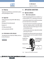
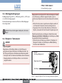
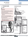
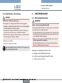
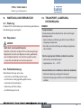
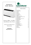
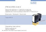
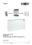
1
PTB 07 ATEX 2063 X
Magnetspule Typ AC19
Geräte mit II 2G Ex m Zulassung
Device with II 2G Ex m approval
Appareils avec mode de protection II 2G Ex m
Operating Instructions
Bedienungsanleitung
Instructions de Service
We reserve the right to make technical changes without notice.
Technische Änderungen vorbehalten.
Sous resérve de modification techniques.
© 2008 - 2011 Bürkert Werke GmbH
Operating Instructions 1112/01_EU-ML_00806067 / Original DE
07 ATEX 2063 X

Solenoid coil AC19, device with II 2G Ex m approval
Table of Contents:
1. OPERATING INSTRUCTIONS....................................................................4
1.1.Symbols............................................................................................... 4
2. INTENDED USE.................................................................................................5
2.1.Restrictions......................................................................................... 5
7. INSTALLATION .............................................................................................. 12
7.1.Safety Instructions..........................................................................12
7.2.Installation.........................................................................................13
7.3.Electrical connection......................................................................14
3. GENERAL SAFETY INSTRUCTIONS......................................................6
8. START-UP.......................................................................................................... 14
8.1.Safety Instructions..........................................................................14
4. GENERAL INFORMATION............................................................................7
4.1.Contact addresses........................................................................... 7
4.2.Warranty.............................................................................................. 8
4.3.Approval.............................................................................................. 8
4.4.Information on the Internet.............................................................. 8
9. MAINTENANCE AND REPAIRS.............................................................. 15
9.1.Maintenance.....................................................................................15
9.2.Repairs...............................................................................................15
9.3.Troubleshooting...............................................................................15
5. APPLICATION CONDITIONS ....................................................................8
5.1.Special conditions............................................................................ 8
5.2.Operating Conditions....................................................................... 9
5.3.Installation conditions.....................................................................10
5.4.Application in petrol pumps..........................................................10
10. TRANSPORT, STORAGE, DISPOSAL............................................... 15
6. TECHNICAL DATA......................................................................................... 11
english
3
07 ATEX 2063 X
Operating instructions
1.
OPERATING INSTRUCTIONS
The operating instructions describe the entire life cycle of the device.
Keep these instructions in a location which is easily accessible to
every user and make these instructions available to every new owner
of the device.
WARNING!
Warns of a potentially dangerous situation!
• Failure to observe the warning may result in serious injuries or
death.
WARNING!
CAUTION!
The operating instructions contain important safety
information!
Failure to observe these instructions may result in hazardous
situations. The operating instructions must be read and
understood.
• Carefully read the operating instructions before using the device.
• In particular observe the chapter entitled "Intended use", and
"General safety instructions" as well as the chapter entitled
"Application conditions of the coil AC19".
Warns of a possible danger!
• Failure to observe the warning may result in moderately serious
or minor injuries.
NOTE!
Warns of damage to property!
designates additional significant information, tips and
recommendations.
1.1. Symbols
To identify important information, the following symbols are used in
the operating instructions:
refers to information in these operating instructions or in
other documentation.
DANGER!
Warns of an immediate danger!
• Failure to observe the warning may result in a fatal or serious
injury.
4
english
→→designates a procedure which you must carry out.
07 ATEX 2063 X
Intended Use
2.
INTENDED USE
WARNING!
Incorrect use of the coil AC19 can be dangerous to people,
nearby equipment and the environment.
• The solenoid coil AC19 is used to actuate valves which control
gaseous or liquid media. It was designed for use in explosion
group II, category 2D, Ex mbD, IP64, T130°C and in explosion
group II, category 2G and temperature class T4 (see specifica- approval plate).
tions on the
• The coil AC19 is always attached to the core feed pipe of the
valve fitting and secured with a nut. In this way coil and valve
body are connected in such a way that a closed system is formed which may also be used as a category 2 device to control
petrol in petrol pumps. For this application a valve body made of
metal (brass, aluminium or stainless steel) must be used.
When using the device, observe the permitted data, operating
conditions and application conditions which
• Any other use is considered improper use.Bürkert is not liable
for any resulting damage. The user alone bears the risk.
• Use the device only as intended.
2.1. Restrictions
If exporting the system/device, observe any existing restrictions.
2.1.1. Explosion protection approval
The explosion protection approval is only valid if you use the modules
and components authorised by Bürkert, as described in these operating instructions.
The coil AC19 may be used only in combination with the valve types
released by Bürkert, otherwise the explosion protection approval will
be terminated!
If you make unauthorised changes to the system, the modules or components, the explosion protection approval will be terminated.
–are specified in the operating instructions for the solenoid coil
AC19, on the rating plate, in the contract documents
–as well as in the operating instructions for the solenoid valve
actuated with the coil.
The coil may be used only in conjunction with third-party devices
and components recommended and authorised by Bürkert.
Correct transportation, correct storage and installation and careful
use and maintenance are essential for reliable and problem-free
operation.
english
5
07 ATEX 2063 X
General Safety Instructions
3.
GENERAL SAFETY INSTRUCTIONS
These safety instructions do not make allowance for any
• contingencies and events which may arise during the installation,
operation and maintenance of the devices.
• local safety regulations, whereby the operator is responsible for their
compliance, by the installation personnel too.
DANGER!
Danger of explosion!
Following installation, solenoid coil and valve body form a closed
system. If used in the EX area, there is a danger of explosion if the
system is opened during operation!
• The system must not be disassembled during operation.
Danger of explosion caused by electrostatic charge!
If there is a sudden discharge from electrostatically charged devices
or persons, there is a danger of explosion in the EX area.
• Take appropriate measures to prevent electrostatic charges in the
EX area.
• Clean the device surface of the solenoid valve by gently wiping
it with a damp cloth
6
english
DANGER!
Risk of electric shock!
There is a serious risk of injury when reaching into the equipment.
• Only trained electrical engineers may work on the electrical
system.
• Before starting work, always switch off the power supply and
safeguard to prevent re-activation!
• Observe applicable accident prevention and safety regulations
for electrical equipment!
Danger of burns/danger of fire during long-term operation!
The solenoid coil may become very hot during long-term operation.
• Take hold of a device which has been running for a prolonged
period with protective gloves only.
Danger – high pressure!
There is a serious risk of injury when reaching into the system.
• Only skilled and instructed personnel may work on the system
with suitable tools.
• Before disconnecting lines and valves, switch off the pressure
and bleed the lines.
• During installation note the direction of flow.
• Observe applicable accident prevention and safety regulations
for pressurised devices!
• After an interruption in the power supply or fluid supply, ensure
that the process is restarted in a defined or controlled manner!
07 ATEX 2063 X
General Information
WARNING!
General hazards!
• Do not use the valve fitting or the complete device as a lever to
screw the valve into the line system.
• Do not put any loads on the housing (e.g. by placing objects on
it or standing on it).
• Do not make any external modifications to the device housings.
Do not paint the housing parts or screws.
Unintentional activation or unauthorised impairment of the system
may cause general hazardous situations through to physical injury.
• Take appropriate measures to prevent the system from being
accidentally actuated!
• Do not make any unauthorised changes to the system.
Non-observance of the generally acknowledged safety rules may
cause general hazardous situations through to physical injury.
• Observe the generally acknowledged safety rules for resource
planning and operation of the coil AC19 and the associated
solenoid valve.
4.
GENERAL INFORMATION
4.1. Contact addresses
Germany
Bürkert Fluid Control Systems
Sales Center
Christian-Bürkert-Str. 13-17
D-74653 Ingelfingen
Tel. + 49 (0) 7940 - 10 91 111
Fax + 49 (0) 7940 - 10 91 448
E-mail: [email protected]
International
Contact addresses can be found on the final pages of the printed
operating instructions.
And also on the Internet at:
www.burkert.com
The coil AC19 was developed with due consideration
given to the accepted safety rules and is state-of-the-art.
However, dangers can still arise.
Operate the coil AC19 and the associated solenoid valve in
perfect working order only and in accordance with the operating
instructions.
english
7
07 ATEX 2063 X
Application conditions
4.2. Warranty
5.
The warranty is only valid if the device is used as intended in accordance
with the specified application conditions.
APPLICATION CONDITIONS
5.1. Special conditions
5.1.1. Short-circuit protection
4.3. Approval
The EC Type Examination Certificate PTB 07 ATEX 2063 X was
issued by the
PTB (Physikalisch Technische Bundesanstalt)
Bundesallee 100
38116 Braunschweig (Germany)
which also audits production (CE0102).
4.4. Information on the Internet
The operating instructions and data sheets for Bürkert products can
be found on the Internet at:
To protect each solenoid against short-circuit, a fuse (max. 3 x Ib in
accordance with IEC 60127-2-1), corresponding to the rated current,
or a motor protection switch with short-circuit and thermal quick release
(set to rated current) must be connected upstream.
• At very low rated currents of the solenoid the fuse with the lowest
current value is adequate according to the stated IEC standard.
This fuse may be housed in the associated supply unit or must be
connected separately upstream.
• The fuse rated voltage must be the same or higher than the indicated
nominal voltage of the solenoid.
• The interruption rating of the fuse link must be the same or higher than
the maximum short-circuit current to be accepted at the installation
site (usually 1500 A).
Example 2/2-way
solenoid valve:
www.burkert.com
The nominal value of
the fuse is indicated
on the solenoid
Solenoid coil AC19
Valve body
Fig. 1 :
8
english
Fuse
F.,..A
Example of coil AC19 as part of a closed system.
07 ATEX 2063 X
Application conditions
5.2. Operating Conditions
5.2.2. Minimum dimensions
For operation of the solenoid coils Type AC19-..-.-PF09 and Type
AC19-..-.-PF10 observe the following requirements.
Valve body:
5.2.1. Materials
For the selection of materials for the system observe the applicationspecific, safety requirements.
55 mm x 36 mm x 30 mm (L x W x H)
A larger valve body with improved thermal conductivity may be
used at any time.
5.2.3. Application temperature range:
Valve body:
DANGER!
DANGER!
Danger of explosion!
Danger of explosion!
If the system is used as a category 2 device, only valve bodies
made of metal can ensure the required safety for the control of
petrol in petrol pumps!
• Use only valve bodies made of metal (brass, aluminium or
stainless steel) for the control of petrol in petrol pumps with
category 2 devices.
• For use in petrol pumps
Metal (brass, aluminium, stainless steel)
• Other applications
Metal (brass, aluminium, stainless steel) or plastic (e.g. polyamide
PA 6 GV ...)
Sheathing of the electrical connection cables:
Type AC19-..-.-PF09
PVC
Type AC19-..-.-PF10
PUR
If the max. permitted temperature values for the coil AC19 are
exceeded, there is a danger of explosion.
• Observe the temperature specifications for the coil
• Observe any restrictions by the max. permitted values for the
solenoid valve combined with the coil.
Temperature values of the solenoid coil AC19
Maximum surface temperatur of the coil at 60 °C ambient temperature and nominal voltage:110 °C (for gas)
130 °C (for dust)
Temperature class (for gas)
T4
Max. permitted ambient temperatures
Type
Material of the electrical
connection cables
AC19-..-.-PF09 PVC
AC19-..-.-PF10 PUR
english
Max. permitted
ambient temperature
-40 – +55 °C
-40 – +60 °C
9
07 ATEX 2063 X
Application conditions
5.3. Installation conditions
The solenoid coils Type AC19-..-.-PF09 to Type AC19-..-.-PF10 are
suitable for single installation only.
The connection cables must be laid permanently to protect against
damage.
If the system is used as a category 2 device, only valve bodies
made of metal can ensure the required safety for the control of
petrol in petrol pumps!
• Use only valve bodies made of metal (brass, aluminium or
stainless steel) for the control of petrol in petrol pumps with
category 2 devices.
Also observe the specifications in the chapter entitled
"Technical Data".
5.4. Application in petrol pumps
DANGER!
Example:
2/2-way solenoid valve
Danger of explosion!
Following installation, solenoid coil and valve body form a closed
system. If used in the EX area, there is a danger of explosion if the
system is opened during operation!
• The system must not be disassembled during operation.
• The valve body may be repaired by the manufacturer only.
Solenoid valves together with the coil AC19 may be used as
category 2 devices only for the control of petrol if there is no air
and no oxygen in the closed system.
• Ensure that the closed system contains no air or oxygen or
cannot be penetrated by air or oxygen.
• When switching off or starting up the system, ensure that neither air nor oxygen has penetrated the system.
10
english
Solenoid coil AC19
Valve body
Fig. 2 :
Example of coil AC19 as part of a closed system.
07 ATEX 2063 X
Technical Data
6.
TECHNICAL DATA
Wording on the rating plate:
DANGER!
Device group
Danger of explosion!
If the safety data and values specified on the rating plate are
not observed or maintained, hazardous situations may be the
consequence!
• Observe the degree of protection and temperature class when
using the device.
It is a safety risk to exceed the voltage indicated on the rating
plate, as this may cause the device to overheat!
• Do not connect the device to a higher voltage than indicated on
the rating plate.
Example
Fuse
F. , . . A
PTB 07 ATEX 2063 X
IEC Ex PTB08.0016X
II 2G Exmb II T4
II 2G Ex mbD21 IP64
Tmed130°C 24V AC/DC
12W AC19-U5-K-PF09
Device category
Ignition protection type
Gas group
II 2G Exmb II T4
II 2D Ex mbD21 IP64
Protection class:
PTB approval no.
PTB 07 ATEX 2063 X
IEC Ex PTB08.0016X
II 2G Exmb II T4
II 2D Ex mbD21 IP64
Tmed130°C 24V AC/DC
12W AC19-U5-K-PF09
IEC explosion protection
approval no.
-Maximum surface
temperatur of the coil
(for dust)
- Voltage
- Current type
- Power consumption
- Coil type
-Connection size forfluid component
-Coil size
Ident. no.
Serial no. of the coil
-Code (specific to
company)
Monitoring centre
Fig. 3 :
Temperature class
Example of rating plate for coil AC19 as part of a closed system.
Date of manufacture - factory/month/year
english
11
07 ATEX 2063 X
Installation
6.4.1. Electrical Data
Note the electrical data as specified on the rating plate.
7.
INSTALLATION
7.1. Safety Instructions
DANGER!
Danger of explosion!
Following installation, solenoid coil and valve body form a closed
system. If used in the EX area, there is a danger of explosion if the
system is opened during operation!
• The system must not be disassembled during operation.
Danger of explosion caused by electrostatic charge!
If there is a sudden discharge from electrostatically charged devices
or persons, there is a danger of explosion in the EX area.
• Take appropriate measures to prevent electrostatic charges in the
EX area.
• Clean the device surface of the solenoid valve by gently wiping
it with a damp cloth
Risk of electric shock!
There is a serious risk of injury when reaching into the equipment.
• Only trained electrical engineers may work on the electrical
system.
• Before starting work, always switch off the power supply and
safeguard to prevent re-activation!
• Observe applicable accident prevention and safety regulations
for electrical equipment!
12
english
07 ATEX 2063 X
Installation
DANGER!
Risk of short-circuit!
Damaged connection cables may cause a short-circuit.
• The connection cables for the coil must be laid permanently and
protected against damage.
Danger of burns/danger of fire during long-term operation!
The solenoid coil may become very hot during long-term operation.
• Take hold of a device which has been running for a prolonged
period with protective gloves only.
7.2. Installation
The solenoid valve with integrated coil AC19 can be installed in any location. Preferably with top-mounted drive.
Prior to installation:
→→Clean any dirt off the pipelines and flange connections.
Installation:
WARNING!
Risk of injury from leaking connections
WARNING!
Danger – high pressure!
There is a serious risk of injury when reaching into the system.
• Only skilled and instructed personnel may work on the system
with suitable tools.
• Before disconnecting lines and valves, switch off the pressure
and bleed the lines.
• Observe applicable accident prevention and safety regulations
for pressurised devices!
• After an interruption in the power supply or fluid supply, ensure
that the process is restarted in a defined or controlled manner!
Danger of explosion!
There is a danger of explosion in fuel pumps if oxygen or air penetrates the medium through leaking connections.
Risk of injury from escaping medium!
Medium which escapes through leaking connections may result in
injuries (e.g. burns or chemical burns).
• Carefully seal the connection lines.
→→Seal pipeline connections with PTFE tape. The tape must not be
dropped into the pipelines.
→→Screw in pipelines.
Important for function of the device!
Note the direction of flow.
→→Check valve for leakage.
english
13
07 ATEX 2063 X
Start-Up
7.3. Electrical connection
DANGER!
8.
START-UP
8.1. Safety Instructions
Risk of electric shock!
WARNING!
There is a serious risk of injury when reaching into the equipment.
• Only trained electrical engineers may work on the electrical
system.
• Before starting work, always switch off the power supply and
safeguard to prevent re-activation!
• Observe applicable accident prevention and safety regulations
for electrical equipment!
→→Connect the power
→→Always connect protective conductor!
The connection cable is encapsulated with the coil AC19
and cannot be removed.
Danger due to improper operation!
Improper operation may result in injuries as well as damage to the
device and the area around it.
• Before start-up, ensure that the operating personnel are familiar
with and completely understand the contents of the operating
instructions.
• In particular observe the safety instructions and intended use.
• The device/the equipment may be started by adequately trained
personnel only.
Before start-up, ensure that
→→the device has been installed according to the instructions,
→→the connection has been made properly,
→→the device is not damaged.
14
english
07 ATEX 2063 X
Maintenance and Repairs
9.
MAINTENANCE AND REPAIRS
9.1. Maintenance
10. TRANSPORT, STORAGE, DISPOSAL
NOTE!
The coil AC19 is maintenance-free provided the application conditions
described in the instructions are observed
Transport damages!
9.2. Repairs
• During transportation protect the device against wet and dirt in
shock-resistant packaging.
DANGER!
Danger - improper repairs!
Following repairs, the safety and function of the coil AC19 and the
corresponding solenoid valve cannot be guaranteed unless the
repairs were carried out by the manufacturer.
• Have the device repaired by the manufacturer only!
9.3. Troubleshooting
In the event of malfunctions, make sure that
→→the device has been installed according to the instructions,
→→the connection has been made properly,
→→the device is not damaged,
→→the voltage and pressure have been switched on,
→→the pipelines are free.
Inadequately protected equipment may be damaged during
transport.
• Avoid exceeding or dropping below the allowable storage
temperature.
Incorrect storage may damage the device.
• Store the device in a dry and dust-free location!
• Storage temperature: -40 … +55 °C.
Damage to the environment caused by device components
contaminated with media.
• Ensure the device and packaging are disposed of in an environmentally sound manner.
• Observe applicable regulations relating to refuse disposal and
the environment.
english
15
07 ATEX 2063 X

16
english
PTB 07 ATEX 2063 X
Magnetspule AC19, Gerät mit II 2G Ex m Zulassung
Inhalt:
1. BEDIENUNGSANLEITUNG....................................................................... 18
1.1.Darstellungsmittel............................................................................18
2. BESTIMMUNGSGEMÄSSE VERWENDUNG.................................... 19
2.1.Beschränkungen.............................................................................19
7. MONTAGE ....................................................................................................... 26
7.1.Sicherheitshinweise........................................................................26
7.2.Montage............................................................................................27
7.3.Elektrischer Anschluss...................................................................28
3. ALLGEMEINE SICHERHEITSHINWEISE........................................... 20
8. INBETRIEBNAHME....................................................................................... 28
8.1.Sicherheitshinweise........................................................................28
4. ALLGEMEINE HINWEISE........................................................................... 21
4.1.Kontaktadressen..............................................................................21
4.2.Gewährleistung. .............................................................................22
4.3.Zulassungen.....................................................................................22
4.4.Informationen im Internet...............................................................22
9. WARTUNG UND REPARATUR................................................................ 29
9.1.Wartung.............................................................................................29
9.2.Reparatur..........................................................................................29
9.3.Fehlerbehebung...............................................................................29
5. EINSATZBEDINGUNGEN ........................................................................ 22
5.1.Besondere Bedingungen..............................................................22
5.2.Betriebsbedingungen.....................................................................23
5.3.Montagebedingungen....................................................................24
5.4.Einsatz in Tanksäulen.....................................................................24
10. TRANSPORT, LAGERUNG, ENTSORGUNG.................................. 29
6. TECHNISCHE DATEN................................................................................. 25
deutsch
17
PTB 07 ATEX 2063 X
Bedienungsanleitung
1.
BEDIENUNGSANLEITUNG
WARNUNG!
Die Bedienungsanleitung beschreibt den gesamten Lebenszyklus
des Gerätes. Bewahren Sie diese Anleitung so auf, dass sie für jeden
Benutzer gut zugänglich ist und jedem neuen Eigentümer des Gerätes
wieder zur Verfügung steht.
Warnt vor einer möglicherweise gefährlichen Situation!
• Bei Nichtbeachtung drohen schwere Verletzungen oder Tod.
VORSICHT!
WARNUNG!
Die Bedienungsanleitung enthält wichtige Informationen zur
Sicherheit!
Das Nichtbeachten dieser Hinweise kann zu gefährlichen Situationen führen. Die Anleitung muss gelesen und verstanden
werden.
• Lesen Sie die Bedienungsanleitung vor dem Einsatz des Gerätes
sorgfältig durch.
• Beachten Sie vor allem die Kapitel „Bestimmungsgemäße
Verwendung“, und „Allgemeine Sicherheitshinweise“ sowie das
Kapitel „Einsatzbedingungen der Spule AC19“.
Warnt vor einer möglichen Gefährdung!
• Nichtbeachtung kann mittelschwere oder leichte Verletzungen
zur Folge haben.
HINWEIS!
Warnt vor Sachschäden!
bezeichnet wichtige Zusatzinformationen, Tipps und
Empfehlungen.
1.1. Darstellungsmittel
Für die Kennzeichnung wichtiger Informationen werden in der
Anleitung folgende Darstellungsmittel verwendet:
verweist auf Informationen in dieser Bedienungsanleitung
oder in anderen Dokumentationen.
GEFAHR!
Warnt vor einer unmittelbaren Gefahr!
• Bei Nichtbeachtung sind Tod oder schwere Verletzungen die
Folge.
18
deutsch
→→markiert einen Arbeitsschritt, den sie ausführen müssen.
PTB 07 ATEX 2063 X
Bestimmungsgemässe Verwendung
2.
BESTIMMUNGSGEMÄSSE
VERWENDUNG
WARNUNG!
Bei nicht bestimmungsgemäßem Einsatz der Spule AC19
können Gefahren für Personen, Anlagen in der Umgebung
und die Umwelt entstehen.
• Die Magnetspule AC19 dient zum Betätigen von Ventilen welche
gasförmige oder flüssige Medien steuern.
Sie wurde für den Einsatz in in Explosionsgruppe II, Kategorie D,
EX mbD, IP64, T130° und Explosionsgruppe II, Kategorie 2G
und Temperaturklasse T4 konzipiert (siehe Angaben auf dem
- Zulassungsschild).
• Die Spule AC19 wird immer auf das Kernführungsrohr der Ventilarmatur montiert und mittels einer Mutter befestigt. Auf diese
Weise werden Spule und Ventilkörper so verbunden, dass
ein geschlossenes System entsteht, das auch in Tanksäulen
zur Steuerung von Benzin als Kategorie -2- Gerät eingesetzt
werden darf. Für diesen Einsatzzweck muss ein Ventilkörper aus
Metall (Messing, Aluminium oder Edelstahl) verwendet werden.
Eine andere oder darüber hinausgehende Benutzung gilt als nicht
bestimmungsgemäß.
Für hieraus resultierende Schäden haftet Bürkert nicht.
Das Risiko trägt allein der Anwender.
• Setzen Sie das Gerät nur bestimmungsgemäß ein.
Die Spule darf nur in Verbindung mit von Bürkert empfohlenen
bzw. zugelassenen Fremdgeräten und -komponenten eingesetzt
werden.
Voraussetzungen für den sicheren und einwandfreien Betrieb sind
sachgemäßer Transport, sachgemäße Lagerung und Installation
sowie sorgfältige Bedienung und Instandhaltung.
2.1. Beschränkungen
Beachten Sie bei der Ausfuhr des Systems/Gerätes gegebenenfalls
bestehende Beschränkungen.
2.1.1. Ex-Zulassung
Für den Einsatz sind die zulässigen Daten, Betriebs- und Einsatzbedingungen zu beachten, die
Die EX-Zulassung ist nur gültig, wenn Sie die von Bürkert zugelassenen
Module und Komponenten so verwenden, wie es in dieser Bedienungsanleitung beschrieben ist.
–in der Bedienungsanleitung für die Magnetspule AC19, auf dem
Typschild, in den Vertragsdokumenten
Die Spule AC19 dürfen Sie nur in Kombination mit den von Bürkert freigegebenen Ventiltypen einsetzen, andernfalls erlischt die Ex-Zulassung!
–sowie in der Bedienungsanleitung für das mit der Spule
betätigte Magnetventil
Nehmen Sie unzulässige Veränderungen am System, den Modulen
oder Komponenten vor, erlischt die Ex-Zulassung ebenfalls.
spezifiziert sind.
deutsch
19
PTB 07 ATEX 2063 X
Allgemeine Sicherheitshinweise
3.
ALLGEMEINE
SICHERHEITSHINWEISE
GEFAHR!
Gefahr durch elektrische Spannung!
Diese Sicherheitshinweise berücksichtigen keine
• Zufälligkeiten und Ereignisse, die bei Montage, Betrieb und Wartung
der Geräte auftreten können.
• ortsbezogenen Sicherheitsbestimmungen, für deren Einhaltung, auch
in Bezug auf das Montagepersonal, der Betreiber verantwortlich ist.
GEFAHR!
Explosionsgefahr!
Magnetspule und Ventilkörper bilden nach der Montage ein
geschlossenes System. Bei Einsatz im EX-Bereich besteht bei
der Öffnung des Systems im Betriebszustand Explosionsgefahr!
• Das System darf nicht während des Betriebs demontiert werden.
Explosionsgefahr durch elektrostatische Aufladung!
Bei plötzlicher Entladung elektrostatisch aufgeladener Geräte oder
Personen besteht im EX-Bereich Explosionsgefahr.
• Stellen Sie durch geeignete Maßnahmen sicher, dass es im EXBereich zu keinen elektrostatischen Aufladungen kommen kann.
• Reinigen Sie die Geräteoberfläche des Magnetventils nur durch
leichtes Abwischen mit einem feuchten Tuch.
20
deutsch
Bei Eingriffen in die Anlage besteht akute Verletzungsgefahr.
• Arbeiten am elektrischen System dürfen nur von ausgebildenten
Elektrofachkräften durchgeführt werden.
• Schalten Sie vor Beginn der Arbeiten in jedem Fall die Spannung ab und sichern Sie diese vor Wiedereinschalten!
• Beachten Sie die geltenden Unfallverhütungs- und Sicherheitsbestimmungen für elektrische Geräte!
Verbrennungsgefahr/Brandgefahr bei Dauerbetrieb!
Die Magnetspule kann im Dauerbetrieb sehr heiß werden.
• Fassen Sie ein Gerät das bereits länger in Betrieb ist nur mit
Schutzhandschuhen an.
Gefahr durch hohen Druck!
Bei Eingriffen in das System besteht akute Verletzungsgefahr.
• Arbeiten am System dürfen nur durch fachkundiges und unterwiesenes Personal mit geeignetem Werkzeug durchgeführt
werden.
• Schalten Sie vor dem Lösen von Leitungen und Ventilen den
Druck ab und entlüften Sie die Leitungen.
• Beachten Sie beim Einbau die Durchflussrichtung.
• Halten Sie die geltenden Unfallverhütungs- und Sicherheitsbestimmungen für druckbeaufschlagte Geräte ein.
• Gewährleisten Sie nach einer Unterbrechung der elektrischen
oder fluidischen Versorgung einen definierten oder kontrollierten
Wiederanlauf des Prozesses!
PTB 07 ATEX 2063 X
Allgemeine Hinweise
WARNUNG!
4.
ALLGEMEINE HINWEISE
Allgemeine Gefährdungen!
4.1. Kontaktadressen
• Benutzen Sie, zum Einschrauben des Ventils in das Leitungssystem, die Ventilarmatur bzw. das Komplettgerät nicht als Hebel.
Deutschland
• Belasten Sie das Gerät nicht mechanisch (z. B. als Ablage für
Gegenstände oder als Trittstufe).
• Nehmen Sie keine äußerlichen Veränderungen an den Gerätegehäusen vor. Gehäuseteile und Schrauben nicht lackieren.
• Halten Sie für die Einsatzplanung und den Betrieb der Spule
AC19 und des zugehörigen Magnetventils die allgemein anerkannten sicherheitstechnischen Regeln ein.
Unbeabsichtigtes Betätigen oder unzulässige Beeinträchtigung
des Systems können zu allgemeinen Gefahrensituationen bis hin
zur Körperverletzung führen.
• Verhindern Sie durch geeignete Maßnahmen, dass das System
unbeabsichtigt betätigt werden kann!
• Nehmen Sie am System keine unerlaubten Änderungen vor.
Bürkert Fluid Control Systems
Sales Center
Christian-Bürkert-Str. 13-17
D-74653 Ingelfingen
Tel. + 49 (0) 7940 - 10 91 111
Fax + 49 (0) 7940 - 10 91 448
E-mail: [email protected]
International
Die Kontaktadressen finden Sie auf den letzten Seiten der
gedruckten Bedienungsanleitung.
Außerdem im Internet unter:
www.burkert.com
Die Spule AC19 wurde unter Einbeziehung der anerkannten
sicherheitstechnischen Regeln entwickelt und entspricht
dem Stand der Technik. Trotzdem können Gefahren
entstehen.
Betreiben Sie die Spule AC19 und das zugehörige Magnetventil nur in einwandfreiem Zustand und unter Beachtung
der Bedienungsanleitung.
deutsch
21
PTB 07 ATEX 2063 X
Einsatzbedingungen
4.2. Gewährleistung.
5.
Voraussetzung für die Gewährleistung ist der bestimmungsgemäße
Gebrauch der Spule AC19 unter Beachtung der spezifizierten
Einsatzbedingungen.
5.1. Besondere Bedingungen
4.3. Zulassungen
Die EG-Baumusterprüfbescheinigung PTB 07 ATEX 2063 X wurde
von der
PTB (Physikalisch Technische Bundesanstalt)
Bundesallee 100
38116 Braunschweig
EINSATZBEDINGUNGEN
5.1.1. Kurzschlussschutz
Jedem Magneten muss als Kurzschlussschutz eine seinem Bemessungsstrom entsprechende Sicherung (max. 3 x Ib nach IEC 60127-2-1) bzw.
ein Motorschutzschalter mit Kurzschluss- und thermischer Schnellauslösung (Einstellung auf Bemessungsstrom) vorgeschaltet werden.
• Bei sehr kleinen Bemessungsströmen des Magneten ist die Sicherung
mit dem kleinsten Stromwert nach der genannten IEC-Norm ausreichend. Diese Sicherung darf im zugehörigen Versorgungsgerät
untergebracht sein oder muss separat vorgeschaltet werden.
ausgestellt, die auch die Fertigung auditiert (CE0102).
• Die Sicherungs-Bemessungsspannung muss gleich oder größer als
die angegebene Nennspannung des Magneten sein.
4.4. Informationen im Internet
• Das Ausschaltvermögen des Sicherungseinsatzes muss gleich
oder größer als der maximal anzunehmende Kurzschlussstrom am
Einbauort (üblicherweise 1500 A) sein.
Bedienungsanleitungen und Datenblätter der Bürkert Produkte finden
Sie im Internet unter:
www.buerkert.de
Dokumentation
Typ
Beispiel
2/2-WegeMagnetventil:
Magnetspule AC19
Ventilkörper
Bild 1:
22
deutsch
Der Sicherungs-
nennwert ist auf dem Magneten angegeben
Sicherung / Fuse
F.,..A
Beispiel für Spule AC19 als Teil eines geschlossenen
Systems.
PTB 07 ATEX 2063 X
Einsatzbedingungen
5.2. Betriebsbedingungen
5.2.2. Mindestabmessungen
Für den Betrieb der Magnetspulen Typ AC19-..-.-PF09 und
Typ AC19-..-.-PF10 sind die nachfolgenden Anforderungen zu
beachten.
Ventilkörper:
5.2.1. Werkstoffe
Für die Wahl der Werkstoffe des Systems sind die einsatzspezifischen,
sicherheitstechnischen Anforderungen zu beachten.
Ventilkörper:
55 mm x 36 mm x 30 mm (L x B x H)
Ein größerer Ventilkörper mit besserer Wärmeleitfähigkeit darf
jeder Zeit verwendet werden.
5.2.3. Einsatztemperturbereich:
GEFAHR!
Explosionsgefahr!
GEFAHR!
Explosionsgefahr!
Beim Einsatz des Systems als Kategorie-2-Gerät können zur
Steuerung von Benzin in Tanksäulen nur Ventilkörper aus Metall
die geforderte Sicherheit gewährleisten!
• Setzen Sie, bei der Steuerung von Benzin in Tanksäulen mit
Kategorie-2-Geräten, nur Ventilkörper aus Metall (Messing,
Aluminium oder Edelstahl) ein.
• Bei Einsatz in Tanksäulen
Metall (Messing, Aluminium, Edelstahl)
• Sonstige Einsatzzwecke
Metall (Messing, Aluminium, Edelstahl) oder Kunststoff
(z.B. Polyamid PA 6 GV ...)
Ummantelung der elektrischen Anschlussleitungen:
Typ AC19-..-.-PF09
PVC
Typ AC19-..-.-PF10
PUR
Bei Überschreitung der max. zulässigen Temperaturwerte für die
Spule AC19 besteht Explosionsgefahr.
• Halten Sie die Temperaturangaben für die Spule unbedingt ein
• Beachten Sie eventuelle Einschränkungen durch die max. zulässigen Werte für das mit der Spule kombinierte Magnetventil.
Temperaturwerte der Magnetspule AC19
Maximale Oberflächentemperatur der Spule bei 60 °C Umgebungstemperatur und Nennspannung:110 °C (für Gas)
130 °C (für Staub)
Temperaturklasse (für Gas):
T4
Max. zulässige Umgebungstemperaturen
Typ
Material der elektrischen
Anschlussleitungen
AC19-..-.-PF09 PVC
AC19-..-.-PF10 PUR
deutsch
Max. zulässige
Umgebungstemperatur
-40 ... +55 °C
-40 ... +60 °C
23
PTB 07 ATEX 2063 X
Einsatzbedingungen
5.3. Montagebedingungen
Die Magnetspulen Typ AC19-..-.-PF09 bis Typ AC19-..-.-PF10 sind
nur zur Einzelmontage geeignet.
Die Anschlussleitungen müssen zum Schutz vor Beschädigungen
fest verlegt werden.
Beachten Sie auch die Angaben des Kapitels „Technische
Daten“.
5.4. Einsatz in Tanksäulen
GEFAHR!
Explosionsgefahr!
Magnetspule und Ventilkörper bilden nach der Montage ein
geschlossenes System. Bei Einsatz im EX-Bereich besteht bei
der Öffnung des Systems im Betriebszustand Explosionsgefahr!
• Das System darf nicht während des Betriebs demontiert werden.
• Reparaturarbeiten am Ventilkörper dürfen nur vom Hersteller
ausgeführt werden.
Magnetventile mit der Spule AC19 dürfen als Kategorie-2-Geräte
nur zur Steuerung von Benzin eingesetzt werden, wenn im
geschlossenen System keine Luft und kein Sauerstoff vorhanden
ist.
• Stellen Sie sicher, dass im geschlossenen System weder Luft
noch Sauerstoff vorhanden sind oder eindringen können.
• Vergewissern Sie sich, beim Abschalten bzw. Anfahren des
Systems, dass weder Luft oder Sauerstoff eingedrungen sind.
Beim Einsatz des Systems als Kategorie-2-Gerät können zur
Steuerung von Benzin in Tanksäulen nur Ventilkörper aus Metall
die geforderte Sicherheit gewährleisten!
• Setzen Sie, bei der Steuerung von Benzin in Tanksäulen mit
Kategorie-2-Geräten, nur Ventilkörper aus Metall (Messing,
Aluminium oder Edelstahl) ein.
Beispiel:
2/2-Wege-Magnetventil
Magnetspule AC19
Ventilkörper
Bild 2:
24
deutsch
Beispiel für Spule AC19 als Teil eines geschlossenen Systems.
PTB 07 ATEX 2063 X
Technische Daten
6.
TECHNISCHE DATEN
Die Beschriftung des Typschilds:
GEFAHR!
Gerätegruppe
Explosionsgefahr!
Werden die auf dem Typschild spezifizierten, sicherheitstechnischen Daten und Werte nicht beachtet oder eingehalten, können
gefährliche Situationen die Folge sein!
• Beachten Sie für den Einsatz des Gerätes die Schutzart und
Temperaturklasse.
Das Überschreiten der auf dem Typschild angegebenen
Spannung ist ein sicherheitstechnisches Risiko, da dies zur Überhitzung des Gerätes führen kann!
• Schließen Sie das Gerät nicht mit einer höheren, als auf dem
Typschild angegebenen, Spannung an.
Beispiel
Sicherung / Fuse
F. , . . A
PTB 07 ATEX 2063 X
IEC Ex PTB08.0016X
II 2G Exmb II T4
II 2G Ex mbD21 IP64
Tmed130°C 24V AC/DC
12W AC19-U5-K-PF09
Bild 3:
eispiel für Typschild der Spule AC19 als Teil eines
B
geschlossenen Systems
Gerätekategorie
Zündschutzart
Gasgruppe
Temperaturklasse
II 2G Exmb II T4
II 2D Ex mbD21 IP64
Schutzart
PTB 07 ATEX 2063 X
IEC Ex PTB08.0016X
II 2G Exmb II T4
II 2D Ex mbD21 IP64
Tmed130°C 24V AC/DC
12W AC19-U5-K-PF09
Ident-Nr.
Serien-Nr. der Spule
Überwachungungsstelle
deutsch
PTB-Zulassungs-Nr.
IEC Ex-Zulassungs-Nr.
-Max. Oberflächentemperatur der Spule (für
Staub)
- Spannung
- Stromart
-
-
-
-
Leistung
Spulentyp
Anschlussgröße für
Fluidteil
Spulengröße
- Code
(firmenspezifisch)
Herstellerdatum - Werk/Monat/Jahr
25
PTB 07 ATEX 2063 X
Montage
7.
6.4.1. Elektrische Daten
MONTAGE
7.1. Sicherheitshinweise
Elektrische Daten laut Typschild beachten.
GEFAHR!
Explosionsgefahr!
Magnetspule und Ventilkörper bilden nach der Montage ein
geschlossenes System. Bei Einsatz im EX-Bereich besteht bei
der Öffnung des Systems im Betriebszustand Explosionsgefahr!
• Das System darf nicht während des Betriebs demontiert werden.
Explosionsgefahr durch elektrostatische Aufladung!
Bei plötzlicher Entladung elektrostatisch aufgeladener Geräte oder
Personen besteht im EX-Bereich Explosionsgefahr.
• Stellen Sie durch geeignete Maßnahmen sicher, dass es im EXBereich zu keinen elektrostatischen Aufladungen kommen kann.
• Reinigen Sie die Geräteoberfläche des Magnetventils nur durch
leichtes Abwischen mit einem feuchten Tuch.
Gefahr durch elektrische Spannung!
Bei Eingriffen in die Anlage besteht akute Verletzungsgefahr.
• Arbeiten am elektrischen System dürfen nur von ausgebildenten
Elektrofachkräften durchgeführt werden.
• Schalten Sie vor Beginn der Arbeiten in jedem Fall die Spannung ab und sichern Sie diese vor Wiedereinschalten!
• Beachten Sie die geltenden Unfallverhütungs- und Sicherheitsbestimmungen für elektrische Geräte!
26
deutsch
PTB 07 ATEX 2063 X
Montage
GEFAHR!
Gefahr durch Kurzschluss!
Durch beschädigte Anschlussleitungen kann es zum Kurzschluss
kommen.
• Die Anschlussleitungen der Spule müssen fest verlegt und vor
Beschädigungen geschützt werden.
Verbrennungsgefahr/Brandgefahr bei Dauerbetrieb!
Die Magnetspule kann im Dauerbetrieb sehr heiß werden.
• Fassen Sie ein Gerät das bereits länger in Betrieb ist nur mit
Schutzhandschuhen an.
7.2. Montage
Die Einbaulage des Magnetventils mit integrierter
Spule AC19 ist beliebig.
Vorzugsweise mit oben liegendem Antrieb.
Vor der Montage:
→→Rohrleitungen und Flanschanschlüsse von eventuellen Verschmutzungen säubern.
Montage:
WARNUNG!
Verletzungsgefahr durch undichten Anschlüsse
WARNUNG!
Gefahr durch hohen Druck!
Bei Eingriffen in das System besteht akute Verletzungsgefahr.
• Arbeiten am System dürfen nur durch fachkundiges und unterwiesenes Personal mit geeignetem Werkzeug durchgeführt
werden.
• Schalten Sie vor dem Lösen von Leitungen und Ventilen den
Druck ab und entlüften Sie die Leitungen.
• Beachten Sie die geltenden Unfallverhütungs- und Sicherheitsbestimmungen für druckbeaufschlagte Geräte.
• Gewährleisten Sie nach einer Unterbrechung der elektrischen
oder fluidischen Versorgung einen definierten oder kontrollierten
Wiederanlauf des Prozesses.
Explosionsgefahr!
Bei Tankanlagen besteht Explosionsgefahr, wenn durch undichte
Anschlüsse, Sauerstoff oder Luft in das Medium gelangt.
Verletzungsgefahr durch Austritt von Medium!
Durch undichte Anschlüsse austretendes Medium kann zu Verletzungen ( z. B. Verbrennungen oder Verätzungen) führen.
• Dichten Sie die Anschlussleitungen sorgfältig ab.
→→Anschlüsse der Rohrleitungen mit PTFE-Band abdichten. Das
Band darf nicht in die Rohrleitungen gelangen.
→→Rohrleitungen einschrauben.
Wichtig für die Funktion des Gerätes!
Beachten Sie die Durchflussrichtung.
→→Ventil auf Dichtheit prüfen.
deutsch
27
PTB 07 ATEX 2063 X
Inbetriebnahme
8.
7.3. Elektrischer Anschluss
GEFAHR!
INBETRIEBNAHME
8.1. Sicherheitshinweise
Gefahr durch elektrische Spannung!
WARNUNG!
Bei Eingriffen in die Anlage besteht akute Verletzungsgefahr.
• Arbeiten am elektrischen System dürfen nur von ausgebildenten
Elektrofachkräften durchgeführt werden.
• Schalten Sie vor Beginn der Arbeiten in jedem Fall die Spannung ab und sichern Sie diese vor Wiedereinschalten!
• Beachten Sie die geltenden Unfallverhütungs- und Sicherheitsbestimmungen für elektrische Geräte!
→→Elektrisch anschließen
→→Schutzleiter immer anschließen!
Das Anschlusskabel ist mit der Spule AC19 vergossen und
kann nicht demontiert werden.
Gefahr durch unsachgemäßen Betrieb!
Nicht sachgemäßer Betrieb kann zu Verletzungen, sowie Schäden
am Gerät und seiner Umgebung führen.
• Vor der Inbetriebnahme muss gewährleistet sein, dass der Inhalt
der Bedienungsanleitung dem Bedienungspersonal bekannt ist
und vollständig verstanden wurde.
• Besonders zu beachten sind die Sicherheitshinweise und die
Bestimmungsgemäße Verwendung.
• Das Gerät/die Anlage darf nur durch ausreichend geschultes
Personal in Betrieb genommen werden.
Stellen Sie vor Inbetriebnahme sicher, dass
→→das Gerät vorschriftmäßig installiert wurde,
→→der Anschluss ordnungsgemäß ausgeführt wurde,
→→das Gerät nicht beschädigt ist.
28
deutsch
PTB 07 ATEX 2063 X
Wartung und Reparatur
9.
WARTUNG UND REPARATUR
9.1. Wartung
Die Spule AC19 ist, bei Einhaltung der in der Anleitung beschriebenen
Einsatzbedingungen, wartungsfrei
9.2. Reparatur
GEFAHR!
Gefahr durch unsachgemäße Reparatur
Sicherheit und Funktion der Spule AC19 und des dazugehörigen
Magnetventils sind nach einer Reparatur nur dann gewährleistet,
wenn die Reparaturarbeiten vom Hersteller ausgeführt wurden.
• Lassen Sie das Gerät nur vom Hersteller reparieren!
9.3. Fehlerbehebung
Stellen Sie bei Störungen sicher, dass
→→das Gerät vorschriftmäßig installiert wurde,
→→der Anschluss ordnungsgemäß ausgeführt wurde,
→→das Gerät nicht beschädigt ist,
→→Spannung und Druck anliegen,
→→die Rohrleitungen frei sind.
10. TRANSPORT, LAGERUNG,
ENTSORGUNG
HINWEIS!
Transportschäden!
Unzureichend geschützte Geräte können durch den Transport
beschädigt werden.
• Gerät vor Nässe und Schmutz geschützt in einer stoßfesten
Verpackung transportieren.
• Eine Über- bzw. Unterschreitung der zulässigen Lagertemperatur vermeiden.
Falsche Lagerung kann Schäden am Gerät verursachen.
• Gerät trocken und staubfrei lagern!
• Lagertemperatur. -40 … +55 °C.
Umweltschäden durch von Medien kontaminierte Geräteteile.
• Gerät und Verpackung umweltgerecht entsorgen!
• Geltende Entsorgungsvorschriften und Umweltbestimmungen
einhalten.
deutsch
29
PTB 07 ATEX 2063 X

30
deutsch
PTB 07 ATEX 2063 X

Bobine magnétique AC19, appareils avec mode de protection II 2G Ex m
Sommaire:
1. INSTRUCTIONS DE SERVICE................................................................ 32
1.1.Symboles..........................................................................................32
2. UTILISATION CONFORME....................................................................... 33
2.1.Limitations.........................................................................................33
7. MONTAGE......................................................................................................... 40
7.1.Consignes de sécurité...................................................................40
7.2.Montage............................................................................................42
7.3.Raccordement électrique..............................................................42
3. CONSIGNES DE SÉCURITÉ GÉNÉRALES...................................... 34
8. MISE EN SERVICE........................................................................................ 43
8.1.Consignes de sécurité...................................................................43
4. INDICATIONS GÉNÉRALES..................................................................... 36
4.1.Adresses...........................................................................................36
4.2.Garantie légale.................................................................................36
4.3.Homologations.................................................................................36
4.4.Informations sur Internet................................................................36
9. MAINTENANCE ET RÉPARATION......................................................... 43
9.1.Maintenance.....................................................................................43
9.2.Réparation.........................................................................................43
9.3.Dépannage.......................................................................................43
5. CONDITIONS D’UTILISATION .............................................................. 36
5.1.Conditions particulières.................................................................36
5.2.Conditions d’exploitation...............................................................37
5.3.Conditions de montage.................................................................38
5.4.Utilisation dans les pompes à essence......................................38
10. TRANSPORT, STOCKAGE, ÉLIMINATION...................................... 44
6. CARACTÉRISTIQUES TECHNIQUES................................................. 39
français
31
PTB 07 ATEX 2063 X
Instructions de service
1.
INSTRUCTIONS DE SERVICE
Les instructions de service décrivent le cycle de vie complet de l’appareil. Conservez ces instructions de sorte qu’elles soient accessibles
à tout utilisateur et à disposition de tout nouveau propriétaire.
AVERTISSEMENT !
Les instructions de service contiennent des informations
importantes sur la sécurité !
Le non-respect de ces consignes peut entraîner des situations
dangereuses. Les instructions de service doivent être lues et
comprises.
• Lisez attentivement les instructions de service avant d'utiliser
l'appareil.
• Faites particulièrement attention aux chapitres « Utilisation
conforme » et « Consignes de sécurité générales » ainsi que les
« Conditions d'utilisation de la bobine AC 19 ».
1.1. Symboles
DANGER !
Met en garde contre un danger imminent !
• Le non-respect peut entraîner la mort ou de graves blessures.
AVERTISSEMENT !
Met en garde contre une situation éventuellement dangereuse !
• Risque de blessures graves, voire la mort en cas de non-respect.
ATTENTION !
Met en garde contre un risque possible !
• Le non-respect peut entraîner des blessures légères ou de
moyenne gravité.
REMARQUE !
Met en garde contre des dommages matériels !
• L’appareil ou l’installation peut être endommagé(e) en cas de
non-respect.
Désigne des informations supplémentaires importantes, des
conseils et des recommandations d’importance.
Renvoie à des informations dans ces instructions de service
ou dans d’autres documentations.
→→identifie une opération que vous devez effectuer.
32
français
PTB 07 ATEX 2063 X
Utilisation conforme
2.
UTILISATION CONFORME
AVERTISSEMENT !
L'utilisation non conforme de la bobine AC19 peut présenter
des dangers pour les personnes, les installations proches et
l'environnement.
• La bobine magnétique AC19 sert à actionner les vannes qui
commandent des fluides liquides ou gazeux.Elle a été conçue
pour utilisation dans le groupe d’explosion II, catégorie 2D Ex
mbD, IP64, T130° et le groupe d’explosion II, catégorie 2G et
- plaque
classe de température T4 (voir indications sur la
d’homologation).
• La bobine AC19 est toujours montée sur la conduite de
guidage principale de la robinetterie de soupape et fixée au
moyen d’un écrou. Ainsi, la bobine et le corps de soupape
sont reliés de manière à former un système fermé pouvant être
utilisé également dans les pompes à essence pour commander
l’essence en tant qu’appareil de catégorie 2. Cette utilisation
requiert un corps de soupape métallique (laiton, aluminium ou
acier inoxydable).
Pour l'utilisation, il convient de respecter les données autorisées,
les conditions d'exploitation et d'utilisation spécifiées
–dans les instructions de service pour la bobine magnétique
AC19, sur la plaque signalétique, dans les documents de
contrat
–ainsi que dans les instructions de service de la vanne magnétique actionnée avec la bobine.
français
Toute autre utilisation ou toute utilisation allant au-delà est considérée comme non conforme.
Bürkert décline toute responsabilité pour les dommages qui en
résultent. L’utilisateur est seul à en supporter le risque.
• Veillez à ce que l’utilisation de l’appareil soit toujours conforme.
La bobine peut être utilisée uniquement en association avec les
appareils et composants étrangers recommandés et homologués
par Bürkert.
Les conditions pour l’utilisation sûre et parfaite sont un transport,
un stockage et une installation dans les règles ainsi qu’une utilisation et maintenance parfaites.
2.1. Limitations
Lors de l’exportation du système/de l’appareil, veuillez respecter les
limitations éventuelles existantes.
2.1.1. Homologation Ex
L’homologation Ex n’est valable que si vous utilisez les modules et
composants homologués par Bürkert tel que cela est décrit dans ces
instructions de service.
La bobine AC19 peut être utilisée uniquement avec les types de
soupape autorisés par Bürkert, sinon l’homologation Ex devient
caduque !
L’homologation Ex devient également caduque si vous apportez
des modifications non autorisées au système, aux modules ou aux
composants.
33
PTB 07 ATEX 2063 X
Consignes de sécurité générales
3.
CONSIGNES DE SÉCURITÉ
GÉNÉRALES
Ces consignes de sécurité ne tiennent pas compte
• des hasards et des événements pouvant survenir lors du montage,
de l’exploitation et de l’entretien des appareils.
• des prescriptions de sécurité locales que l’exploitant est tenu de faire
respecter par le personnel chargé du montage.
DANGER !
Risque d'explosion !
Après montage, la bobine magnétique et le corps de soupape
forment un système fermé. Il y a risque d'explosion en cas d'ouverture du système pendant son utilisation dans des zones présentant des risques d'explosion !
• Le système ne doit pas être démonté pendant son utilisation.
Risque d'explosion dû à la charge électrostatique !
Il y a risque d'explosion en cas de décharge soudaine d'appareils ou
de personnes chargés d'électricité statique dans des zones présentant des risques d'explosion.
• Par des mesures appropriées, assurez-vous qu'il ne peut y avoir
de charges électrostatiques dans de telles zones.
• Nettoyez la surface de la vanne magnétique uniquement en
essuyant légèrement avec un chiffon humide .
34
DANGER !
Danger par tension électrique!
Il y a risque important de blessures lors d’interventions sur
l'installation.
• Les travaux sur le système électrique doivent être effectués
uniquement par des électriciens qualifiés.
• Avant d'effectuer des travaux, coupez toujours la tension et
empêchez toute remise sous tension par inadvertance !
• Veuillez respecter les réglementations en vigueur pour les appareils électriques en matière de prévention des accidents ainsi
qu'en matière de sécurité !
Risque de brûlures/d'incendie en fonctionnement continu !
La bobine magnétique peut devenir brûlante en fonctionnement
continu.
• Portez toujours des gants de protection pour toucher un appareil ayant fonctionné pendant longtemps.
Danger dû à la haute pression !
Il y a risque important de blessures lors d’interventions sur le
système.
• Les travaux sur le système doivent être exécutés uniquement par
du personnel qualifié et formé disposant de l’outillage approprié.
• Avant de desserrer les conduites et les soupapes, coupez la
pression et purgez l’air des conduites.
• Lors du montage, respectez le sens du débit.
• Veuillez respecter les réglementations en vigueur pour les appareils sous pression en matière de prévention des accidents ainsi
qu’en matière de sécurité.
français
PTB 07 ATEX 2063 X
Consignes de sécurité générales
• Après une interruption de l’alimentation électrique ou de
l’alimentation en fluides, garantissez un redémarrage défini ou
contrôlé du processus !
AVERTISSEMENT !
Risques d’ordre général !
• N’utilisez pas la robinetterie de soupape ou l’appareil complet comme levier pour visser la soupape dans le système de
conduites.
• Ne soumettez pas l’appareil à des contraintes mécaniques (par
ex. pour déposer des objets ou en l’utilisant comme marche).
• N’apportez pas de modifications à l’extérieur du boîtier. Ne
laquez pas les pièces du corps ni les vis.
La bobine AC19 a été développée dans le respect des
règles reconnues en matière de sécurité et correspond
à l’état actuel de la technique. Néanmoins, des risques
peuvent se présenter.
La bobine AC19 et la vanne magnétique correspondante doivent
être utilisées uniquement en parfait état et en respectant les instructions de service.
L’actionnement involontaire ou l’intervention non autorisée
peut entraîner des situations dangereuses, voire des blessures
corporelles.
• Evitez l’actionnement involontaire du système par des mesures
appropriées !
• N’apportez pas de modifications non autorisées au système.
Le non-respect des règles reconnues en matière de sécurité peut
entraîner des situations à risques, voire des blessures corporelles.
• Respectez les règles reconnues en matière de sécurité pour
planifier l’utilisation et utiliser la bobine AC19 et la vanne
magnétique correspondante.
français
35
PTB 07 ATEX 2063 X
Indications générales
4.
INDICATIONS GÉNÉRALES
5.
CONDITIONS D’UTILISATION
4.1. Adresses
5.1. Conditions particulières
Allemagne
5.1.1. Protection contre les courts-circuits
Bürkert Fluid Control Systems
Sales Center
Christian-Bürkert-Str. 13-17
D-74653 Ingelfingen
Tel. + 49 (0) 7940 - 10 91 111
Fax + 49 (0) 7940 - 10 91 448
E-mail: [email protected]
International
Les adresses se trouvent aux dernières pages des instructions de
service imprimées. Egalement sur internet sous : www.burkert.com
4.2. Garantie légale
La condition pour bénéficier de la garantie est l’utilisation conforme de
la bobine AC19 dans le respect des conditions d’utilisation spécifiées.
4.3. Homologations
Le certificat d’essai CE PTB 07 ATEX 2063 X a été établi par
le PTB (Physikalisch Technische Bundesanstalt)
Bundesallee 100, 38116 Braunschweig
qui effectue également l’audit de production (CE0102).
4.4. Informations sur Internet
Vous trouverez les instructions de service et les fiches techniques
concernant les produits Bürkert sur Internet sous : www.buerkert.fr
36
Pour assurer la protection contre les courts-circuits, il convient de
placer en amont de chaque aimant un fusible correspondant à son
courant évalué (maxi 3 x Ib selon CEI 60127-2-1) ou un disjoncteurprotecteur à déclenchement rapide thermique et de court-circuit
(réglage sur le courant évalué).
• Selon la norme CEI citée, le fusible au valeur de courant le plus faible
suffit lorsque les courants évalués de l’aimant sont très faibles. Ce
fusible peut être logé dans l’appareil d’alimentation correspondant
ou placé séparément en amont.
• La tension de mesure du fusible doit être identique ou supérieure à
la tension nominale indiquée de l’aimant.
La puissance de coupure du fusible doit être identique ou supérieure au courant de court-circuit maximal possible sur le lieu de
montage (habituellement 1 500 A).
Exemple :
vanne magnétique
2/2
Bobine magnétique
AC19
Corps de
soupape
Fig. 1 :
La valeur nominale
du fusible est
indiquée sur l'aimant
Fusible / Fuse
F.,..A
Exemple pour la bobine AC19 en tant que partie d’un système fermé.
français
PTB 07 ATEX 2063 X
Conditions d’utilisation
5.2. Conditions d’exploitation
5.2.2. Dimensions minimales
Les exigences suivantes doivent être respectées pour l’utilisation des
bobines magnétiques des types AC19-..-.-PF09 et AC19-..-.-PF10 .
Corps de soupape :
5.2.1. Matériaux
Les exigences en matière de sécurité spécifiques à l’utilisation doivent
être respectées lors du choix des matériaux du système.
55 mm x 36 mm x 30 mm (L x l x H).
Il est possible d’utiliser à tout moment un corps de soupape plus
grand avec une meilleure conductibilité thermique.
5.2.3. Plage de température d’utilisation :
Corps de soupape :
DANGER !
DANGER !
Risque d'explosion !
Risque d'explosion !
Seuls les corps de soupape métalliques peuvent garantir la
sécurité exigée en cas d'utilisation du système en tant qu'appareil de catégorie 2 pour la commande d'essence dans les
pompes à essence !
• Pour la commande d'essence dans les pompes à essence
avec des appareils de catégorie 2, veuillez utiliser uniquement
des corps de soupape métalliques (laiton, aluminium ou acier
inoxydable).
• Pour l’utilisation dans les pompes à essence
Métal (laiton, aluminium, acier inoxydable)
• Autres utilisations
Métal (laiton, aluminium, acier inoxydable) ou plastique
(par ex. polyamide PA 6 GV ...)
Enveloppes des câbles de raccordement électriques :
Types AC19-..-.-PF09
PVC
Types AC19-..-.-PF10
PUR
français
Il y a risque d'explosion lorsque la température maximale admissible de la bobine AC19 est dépassée.
• Respectez absolument les températures indiquées pour la bobine.
• Respectez les limitations éventuelles imposées par les valeurs
maximales admissibles de la vanne magnétique combinée à la
bobine.
Températures de la bobine magnétique AC19
Température de surface maximale de la bobine à une température
ambiante de 60 °C et tension nominale : 110 °C (pour gaz)
130 °C (pour poussiére)
Classe de température
T4
Températures ambiantes maximales admissibles
Type
Matériau des câbles de
raccordement électriques
AC19-..-.-PF09 PVC
AC19-..-.-PF10 PUR
Température ambiante
maximale admissible
-40 - +55 °C
-40 - +60 °C
37
PTB 07 ATEX 2063 X
Conditions d’utilisation
5.3. Conditions de montage
Les bobines magnétiques des types AC19-..-.-PF09 à AC19-..-.PF10 conviennent uniquement à un montage individuel.
Les câbles de raccordement doivent être posés à demeure pour les
protéger contre les dommages.
Respectez également les indications du chapitre « Caractéristiques techniques ».
5.4. Utilisation dans les pompes à
essence
DANGER !
Risque d'explosion !
Après montage, la bobine magnétique et le corps de soupape
forment un système fermé. Il y a risque d'explosion en cas d'ouverture du système pendant son utilisation dans des zones présentant des risques d'explosion !
• Le système ne doit pas être démonté pendant son utilisation.
• Les travaux de réparation sur le corps de soupape doivent être
effectués uniquement par le fabricant.
Les vannes magnétiques avec la bobine AC19 ne peuvent être
utilisées en tant qu’appareils de catégorie 2 pour la commande
d’essence que si le système fermé est exempt d’air et d’oxygène.
• Assurez-vous de l’absence d’air et d’oxygène dans le système
fermé et que leur pénétration dans le système est impossible.
• Assurez-vous qu’il n’y pas eu pénétration d’air ou d’oxygène à
l’arrêt et au démarrage du système.
Seuls les corps de soupape métalliques peuvent garantir la
sécurité exigée en cas d’utilisation du système en tant qu’appareil de catégorie 2 pour la commande d’essence dans les
pompes à essence !
• Pour la commande d’essence dans les pompes à essence
avec des appareils de catégorie 2, veuillez utiliser uniquement
des corps de soupape métalliques (laiton, aluminium ou acier
inoxydable).
Exemple :
vanne magnétique 2/2
Bobine magnétique AC19
Corps de soupape
Fig. 2 :
38
xemple pour la plaque signalétique de la bobine AC19 en tant
E
que partie d’un système fermé.
français
PTB 07 ATEX 2063 X
Caractéristiques techniques
6.
CARACTÉRISTIQUES TECHNIQUES
Informations sur la plaque signalétique :
DANGER !
Groupe d’appareils
Catégorie d’appareils
Risque d'explosion !
Des situations dangereuses peuvent être créées si les caractéristiques de sécurité et les valeurs spécifiées sur la plaque signalétique ne sont pas respectées !
• Pour l'utilisation de l'appareil, respectez le type de protection et
la classe de température.
Le dépassement de la tension indiquée sur la plaque signalétique
représente un risque en matière de sécurité étant donné que cela
peut entraîner la surchauffe de l'appareil !
• Ne raccordez pas l'appareil à une tension supérieure à celle
indiquée sur la plaque signalétique.
Exemple
Fusible / Fuse
F. , . . A
PTB 07 ATEX 2063 X
IEC Ex PTB08.0016X
II 2G Exmb II T4
II 2G Ex mbD21 IP64
Tmed130°C 24V AC/DC
12W AC19-U5-K-PF09
Fig. 3 :
Type de protection à l’allumage
Groupe de gaz
français
Type de protection
N° d’homologation PTB
PTB 07 ATEX 2063 X
IEC Ex PTB08.0016X
II 2G Exmb II T4
II 2D Ex mbD21 IP64
Tmed130°C 24V AC/DC
12W AC19-U5-K-PF09
N° ID
xemple pour la bobine AC19 en tant que partie d’un système
E
fermé.
Classe de température
II 2G Exmb II T4
II 2D Ex mbD21 IP64
N° d’homologation Ex CEI
- Température de surface
maximale de la bobine
(pour poussiére)
- Tension
- Type de courant
- Puissance
- Type de bobine
- Grandeur de raccordement pour partie
fluide
N° de série de la bobine
- Taille de bobine
Organisme de surveillance
- Code (spécifique à
l’entreprise)
Date fabricant - Usine/Mois/Année
39
PTB 07 ATEX 2063 X
Montage
Caractéristiques électriques
Respectez les caractéristiques électriques selon la plaque
signalétique.
7.
MONTAGE
7.1. Consignes de sécurité
DANGER !
Risque d'explosion !
Après montage, la bobine magnétique et le corps de soupape
forment un système fermé. Il y a risque d'explosion en cas d'ouverture du système pendant son utilisation dans des zones présentant des risques d'explosion !
• Le système ne doit pas être démonté pendant son utilisation.
Risque d'explosion dû à la charge électrostatique !
Il y a risque d'explosion en cas de décharge soudaine d'appareils ou
de personnes chargés d'électricité statique dans des zones présentant des risques d'explosion.
• Par des mesures appropriées, assurez-vous qu'il ne peut y avoir
de charges électrostatiques dans de telles zones.
• Nettoyez la surface de la vanne magnétique uniquement en
essuyant légèrement avec un chiffon humide .
40
français
PTB 07 ATEX 2063 X
Montage
DANGER !
AVERTISSEMENT !
Danger par tension électrique!
Danger dû à la haute pression !
Il y a risque important de blessures lors d’interventions sur
l’installation.
• Les travaux sur le système électrique doivent être effectués
uniquement par des électriciens qualifiés.
• Avant d’effectuer des travaux, coupez toujours la tension et
empêchez toute remise sous tension par inadvertance !
• Veuillez respecter les réglementations en vigueur pour les appareils électriques en matière de prévention des accidents ainsi
qu’en matière de sécurité !
Il y a risque important de blessures lors d'interventions sur le
système.
• Les travaux sur le système doivent être exécutés uniquement
par du personnel qualifié et formé disposant de l'outillage
approprié.
• Avant de desserrer les conduites et les soupapes, coupez la
pression et purgez l'air des conduites.
• Veuillez respecter les réglementations en vigueur pour les appareils sous pression en matière de prévention des accidents ainsi
qu'en matière de sécurité !
• Après une interruption de l'alimentation électrique ou de
l'alimentation en fluides, garantissez un redémarrage défini ou
contrôlé du processus !
Danger dû au court-circuit !
Les câbles de raccordement endommagés peuvent entraîner un
court-circuit.
• Les câbles de raccordement de la bobine doivent être posés à
demeure et protégés pour ne pas être endommagés.
Risque de brûlures/d'incendie en fonctionnement continu !
La bobine magnétique peut devenir brûlante en fonctionnement
continu.
• Portez toujours des gants de protection pour toucher un appareil ayant fonctionné pendant longtemps.
français
41
PTB 07 ATEX 2063 X
Montage
7.2. Montage
La position de montage de la vanne magnétique avec
bobine AC19 intégrée est indifférente.De préférence avec
l'entraînement en haut.
Avant le montage :
→→Nettoyez les tuyauteries et les raccordements à brides afin d’enlever
les éventuelles saletés.
Montage :
AVERTISSEMENT !
Risque de blessures dû aux raccords non étanches
Risque d'explosion !
Les stations-service présentent un risque d'explosion si l'oxygène
ou l'air parvient dans le fluide à cause de raccords non étanches.
Risque de blessures dû à la sortie de fluide !
La sortie de fluide de raccords non étanches peut provoquer des
blessures (par ex. des brûlures ou des brûlures par acide).
• Etanchez les conduites de raccordement avec soin.
7.3. Raccordement électrique
DANGER !
Danger par tension électrique!
Il y a risque important de blessures lors d’interventions sur
l'installation.
• Les travaux sur le système électrique doivent être effectués
uniquement par des électriciens qualifiés.
• Avant d'effectuer des travaux, coupez toujours la tension et
empêchez toute remise sous tension par inadvertance !
• Veuillez respecter les réglementations en vigueur pour les appareils électriques en matière de prévention des accidents ainsi
qu'en matière de sécurité !
→→Raccordez à l’électricité
→→toujours le conducteur de protection !
Le câble de raccordement est surmoulé avec la bobine
AC19 et ne peut pas être démonté.
→→Etanchez les raccords des tuyauteries avec une bande PTFE. La
bande ne doit pas parvenir dans les tuyauteries.
→→Vissez les tuyauteries.
Important pour le fonctionnement de l'appareil !
Respectez le sens du débit.
→→Contrôlez l’étanchéité de la soupape.
42
français
PTB 07 ATEX 2063 X
Mise en service
8.
MISE EN SERVICE
9.
8.1. Consignes de sécurité
MAINTENANCE ET RÉPARATION
9.1. Maintenance
La bobine AC19 ne nécessite pas d’entretien à condition de respecter
les conditions d’utilisation décrites dans les instructions de service.
AVERTISSEMENT !
Danger dû à une utilisation non conforme !
Une utilisation non conforme peut entraîner des blessures et
endommager l'appareil et son environnement.
• Avant la mise en service, il faut s'assurer que le contenu des
instructions de service est connu et parfaitement compris par
les opérateurs.
• Respectez en particulier les consignes de sécurité et l'utilisation
conforme.
• L'appareil/l'installation doit être mis(e) en service uniquement
par un personnel suffisamment formé.
9.2. Réparation
DANGER !
Danger dû à une réparation non conforme !
La sécurité et le fonctionnement de la bobine AC19 et de sa
vanne magnétique ne sont pas garantis après réparation que si
celle-ci a été effectuée par le fabricant.
• Faites réparer l'appareil uniquement par le fabricant !
Avant la mise en service, assurez-vous que
→→l’appareil a été installé dans les règles,
→→le raccordement a été correctement effectué,
→→l’appareil n’est pas endommagé.
9.3. Dépannage
En présence de pannes, assurez-vous que
→→l’appareil a été installé dans les règles,
→→le raccordement a été correctement effectué,
→→l’appareil n’est pas endommagé,
→→la tension et la pression sont disponibles,
→→les tuyauteries ne sont pas obstruées.
français
43
PTB 07 ATEX 2063 X
Transport, Stockage, Élimination
10. TRANSPORT, STOCKAGE,
ÉLIMINATION
REMARQUE !
Dommages dus au transport !
Les appareils insuffisamment protégés peuvent être endommagés
pendant le transport.
• Transportez l’appareil à l’abri de l’humidité et des impuretés et
dans un emballage résistant aux chocs.
• Evitez le dépassement vers le haut ou le bas de la température
de stockage admissible.
Un mauvais stockage peut endommager l’appareil.
• Stockez l’appareil au sec et à l’abri des poussières !
• Température de stockage : -40 … +55 °C.
Dommages à l’environnement causés par des pièces d’appareil contaminées par des fluides.
• Eliminez l’appareil et l’emballage dans le respect de l’environnement !
• Respectez les prescriptions en matière d’élimination des
déchets et de protection de l’environnement en vigueur.
44
français
www.burkert.com