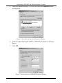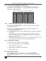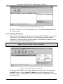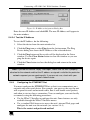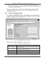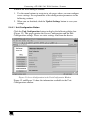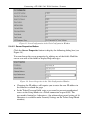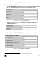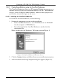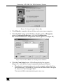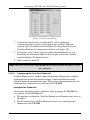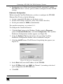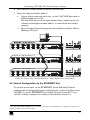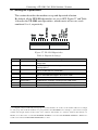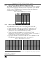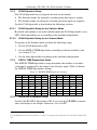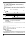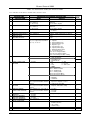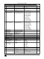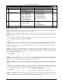
1
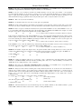
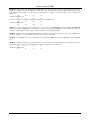
Kramer Electronics, Ltd.
USER MANUAL
Model:
VP-1201
12x1 XGA Switcher / Scanner
Contents
Contents
1
2
3
4
5
5.1
5.2
5.3
5.4
Introduction
Getting Started
Overview
Your VP-1201 12x1 XGA Switcher / Scanner
Connecting a VP-1201 12x1 XGA Switcher / Scanner
Connecting a Single Unit or Multiple VP-1201 Units
Controlling via RS-232 (for example, using a PC)
Controlling via RS-485
Setting the ETHERNET Port and Utilities
1
1
1
2
5
5
7
8
9
5.4.1
5.4.2
5.4.3
5.4.4
5.4.5
5.4.6
Connecting the VP-1201 Ethernet Port
Installing and Running the XPort Configuration Software
Configuring the ETHERNET Port
Using the Web Manager Page
Controlling a Machine using the Com Port Redirector
Using the Com Port Redirector
9
11
13
14
18
23
5.5
Connecting Several VP-1201 Machines
24
5.5.1
5.5.2
Connecting Several VP-1201 Units – Individual Control Configuration
Connecting Several VP-1201 Units – Input Expansion Configuration
24
26
5.6
5.7
Control Configuration via the ETHERNET Port
Setting the Dipswitches
27
28
5.7.1
5.7.2
5.7.3
5.7.4
5.7.5
5.7.6
MACH. ADDR. (Machine Address) Dipswitches Setup
MACH. # (Machine Number) Dipswitches Setup
SCAN Dipswitch Setup
DWELL TIME Dipswitches Setup
VALID ONLY Dipswitch Setup
FLASH PROG Dipswitch Setup
29
29
30
30
30
31
5.8
6
6.1
6.2
7
7.1
7.2
7.3
8
9
10
Resetting the Unit
Operating the VP-1201
Switching between Modes
The VP-1201 Input Buttons
Firmware Upgrading
Downloading from the Internet
Connecting the PC to the RS-232 Port
Upgrading Firmware
Technical Specifications
Table of Hex Codes for Serial Communication
Kramer Protocol 2000
31
31
31
32
33
33
33
33
38
38
39
i
Contents
Figures
Figure 1: VP-1201 12x1 XGA Switcher / Scanner
Figure 2: VP-1201 Underside Panel
Figure 3: Connecting the VP-1201
Figure 4: Connecting a PC without using a Null-modem Adapter
Figure 5: Controlling via RS-485 (for example, using an RC-3000)
Figure 6: Local Area Connection Properties Window
Figure 7: Internet Protocol (TCP/IP) Properties Window
Figure 8: XPort™ Installer Main Dialog Box
Figure 9: Device Found on the Network
Figure 10: IP Address Assignment Dialog Box
Figure 11: ETHERNET Port Web-Manager
Figure 12: Server Configuration in the Unit Configuration Window
Figure 13: Port Configuration in the Unit Configuration Window
Figure 14: Server Properties in the Unit Configuration Window
Figure 15: Serial Port Settings Window
Figure 16: Dedicated Connection Window
Figure 17: Flush Mode Input Buffer Window
Figure 18: Com Port Redirector Welcome Screen
Figure 19: Setup Complete Dialog Box
Figure 20: Com Port Redirector Configuration Window
Figure 21: Port Setup Window
Figure 22: IP Service Setup Dialog Box
Figure 23: Port Settings Window
Figure 24: Silent Mode Checked in the RDCfg Window
Figure 25: Connecting VP-1201 Machines – Individual Control Configuration
Figure 26: Connecting VP-1201 Machines – Input Expansion Configuration
Figure 27: VP-1201 Dipswitches
Figure 28: VP-1201 Input Buttons Illuminated (I)
Figure 29: VP-1201 Input Buttons Illuminated (II)
Figure 30: Splash Screen
Figure 31: Atmel – Flip Window
Figure 32: Device Selection Window
Figure 33: Selecting Device from Selection Window
Figure 34: Loading the Hex
Figure 35: RS-232 Window
Figure 36: Atmel – Flip Window (Connected)
Figure 37: Atmel – Flip Window (Operation Completed)
ii
3
4
6
7
8
10
10
12
12
13
14
15
16
16
17
17
17
18
19
19
20
21
22
23
25
27
28
32
32
34
34
34
35
35
36
36
37
KRAMER: SIMPLE CREATIVE TECHNOLOGY
Contents
Tables
Table 1: Front Panel VP-1201 12x1 XGA Switcher / Scanner Features
Table 2: Rear Panel VP-1201 12x1 XGA Switcher / Scanner Features
Table 3: VP-1201 Underside Panel Features
Table 4: Crossover Cable RJ-45 PINOUT
Table 5: Straight-through Cable RJ-45 PINOUT
Table 6: Web Manager Window Buttons
Table 7: Port Settings Description
Table 8: Dipswitch Settings
Table 9: MACH. ADDR. Dipswitch Settings
Table 10: MACH. # Dipswitch Settings
Table 11: DWELL TIME Dipswitch Settings
Table 12: Technical Specifications of the VP-1201
Table 13: VP-1201 Hex Codes for Switching via RS-232/RS-485
Table 14: VP-1201 Hex Codes for Valid Input Detection Request
Table 15: Protocol Definitions
Table 16: Instruction Codes for Protocol 2000
4
4
5
9
11
14
22
28
29
29
30
38
38
38
39
40
iii
Introduction
1
Introduction
Welcome to Kramer Electronics (since 1981): a world of unique, creative and
affordable solutions to the infinite range of problems that confront the video,
audio and presentation professional on a daily basis. In recent years, we have
redesigned and upgraded most of our line, making the best even better! Our
350-plus different models now appear in 8 Groups1, which are clearly defined
by function.
Congratulations on purchasing your Kramer VP-1201 12x1 XGA Switcher /
Scanner, which is ideal for the following typical applications:
Any professional system requiring a 12x1 switcher / scanner
Production studios
Security, CCTV, and home theater systems
The package includes the following items:
VP-1201 12x1 XGA Switcher / Scanner
Power cord and Null-modem adapter
Windows®-based Configuration Manager XPort software and Com Port
Redirector
Windows®-based Kramer control software
This user manual2
2
Getting Started
We recommend that you:
Unpack the equipment carefully and save the original box and packaging
materials for possible future shipment
Review the contents of this user manual
Use Kramer high performance high resolution cables3
3
Overview
The high performance VP-1201 12x1 XGA Switcher / Scanner is a true
switcher / scanner, routing up to 12 sources to one output.
1 GROUP 1: Distribution Amplifiers; GROUP 2: Video and Audio Switchers, Matrix Switchers and Controllers; GROUP 3:
Video, Audio, VGA/XGA Processors; GROUP 4: Interfaces and Sync Processors; GROUP 5: Twisted Pair Interfaces;
GROUP 6: Accessories and Rack Adapters; GROUP 7: Scan Converters and Scalers; and GROUP 8: Cables and Connectors
2 Download up-to-date Kramer user manuals from our Web site at http://www.kramerelectronics.com
3 The complete list of Kramer cables is on our Web site at http://www.kramerelectronics.com
1
Your VP-1201 12x1 XGA Switcher / Scanner
The VP-1201 features:
A bandwidth of 400MHz for RGB signals
Input signal detection
Manual switching or automatic scanning of inputs (or Valid-Only inputs)
Signal switching delay time, ranging from 1 to 16 seconds
Control the VP-1201 using the front panel buttons, or remotely via:
RS-485 or RS-232 serial commands transmitted by a touch screen system,
PC, or other serial controller
ETHERNET
The Kramer RC-IR1 Infra-Red Remote Control Transmitter1
The VP-1201 is dependable, rugged and fits into one vertical space (1U) of a
standard 19" rack.
To achieve the best performance:
Connect only good quality connection cables, thus avoiding interference,
deterioration in signal quality due to poor matching, and elevated noiselevels (often associated with low quality cables)
Avoid interference from neighboring electrical appliances and position
your Kramer VP-1201 away from moisture, excessive sunlight and dust
4
Your VP-1201 12x1 XGA Switcher / Scanner
Figure 1 illustrates the front and rear panels of the VP-1201. Table 1 and
Table 2 define the front and rear panels of the VP-1201, respectively.
1 Previously known as the IR-1/IR-1-01
2
KRAMER: SIMPLE CREATIVE TECHNOLOGY
Figure 1: VP-1201 12x1 XGA Switcher / Scanner
Your VP-1201 12x1 XGA Switcher / Scanner
3
Your VP-1201 12x1 XGA Switcher / Scanner
Table 1: Front Panel VP-1201 12x1 XGA Switcher / Scanner Features
#
1
IR Receiver
Feature
2
3
POWER Switch
1
INPUT SELECTOR Buttons
Function
The red LED is illuminated when receiving signals from the
Kramer Infra-Red remote control transmitter
Illuminated switch supplying power to the unit
Select the input to switch to the output (from 1 to 12):
The blue LED illuminates when a signal is detected on the input
The red LED illuminates when the input is routed to the output
but no signal is detected on the input
Both the blue and red LEDs illuminate (creating purple) when a
signal is transmitted to the output
Table 2: Rear Panel VP-1201 12x1 XGA Switcher / Scanner Features
#
4
5
6
7
8
9
10
Feature
HD15F Input Connectors
HD15F BUS Connector
HD15F BUS LOOP Connector
BUS TERM Button
HD15F OUTPUT Connector
Setup Dipswitches
ETHERNET Connector
11
12
13
RS-232 DB 9F Connector
RS-485 Connector
Power Connector with Fuse
Function
Connect to the video sources (IN1 through IN12)
Bus connector for cascading VP-1201 units
Loop for bus connector
Press for BUS termination
Connects to the output acceptor
For machine setup (see section 5.7)
Connects to the PC or other controller through computer
networking
Connects to the PC or other Serial Controller
Used for bi-directional communication with another unit
AC connector enabling power supply to the unit
Figure 2 illustrates the underside of the VP-1201 unit and Table 3 defines the
underside features.
Enlarged View
1
2
3
4
Figure 2: VP-1201 Underside Panel
1 The INPUT SELECTOR buttons are also used to set the highest machine number (see section 5.5.2)
4
KRAMER: SIMPLE CREATIVE TECHNOLOGY
Connecting a VP-1201 12x1 XGA Switcher / Scanner
Table 3: VP-1201 Underside Panel Features
#
1
2
3
4
5
Feature
RESET Button
GREEN LEVEL Trimmer
RED LEVEL Trimmer
BLUE LEVEL Trimmer
Function
Press to reset the unit prior to a firmware upgrade (see section 5.8)
1
Adjusts the green level
1
Adjusts the red level
1
Adjusts the blue level
Connecting a VP-1201 12x1 XGA Switcher / Scanner
This section describes how to:
Connect the VP-1201 unit (see section 5.1)
Connect the VP-1201 to a controlling device via:
RS-232 (see section 5.2)
RS-485 (see section 5.3)
ETHERNET (see sections 5.4 and 5.6)
Connect several VP-1201 machines (see section 5.5)
Set the dipswitches (see section 5.7)
Reset the unit (see section 5.8)
5.1 Connecting a Single Unit or Multiple VP-1201 Units
To connect the VP-1201 12x1 XGA Switcher / Scanner, do the following:
1. Connect the following to the rear panel:
Video sources (see Figure 3)
Output acceptor
Power cord
2. Connect to a controlling device (optional – see sections 5.2, 5.3 and 5.4).
3. Connect the RS-485 port to additional units (optional – see sections
5.5.1 and 5.5.2).
4. Connect the BUS ports to additional units (optional – see section 5.5.2).
5. Set the dipswitches (see section 5.7).
1 Insert a screwdriver into the small hole and carefully rotate it to adjust the level
5
Connecting a VP-1201 12x1 XGA Switcher / Scanner
Computer Graphic
Source 1
RS-232
Computer Graphic
Source 12
Display
Figure 3: Connecting the VP-1201
6
KRAMER: SIMPLE CREATIVE TECHNOLOGY
Connecting a VP-1201 12x1 XGA Switcher / Scanner
5.2 Controlling via RS-232 (for example, using a PC)
To connect a PC to the VP-1201 unit1, using the Null-modem adapter
provided with the machine (recommended):
Connect the RS-232 DB9 rear panel port on the VP-1201 unit to the
Null-modem adapter and connect the Null-modem adapter with a 9-wire
flat cable2 to the RS-232 DB9 port on your PC
To connect a PC to the VP-1201 unit1, without using a Null-modem adapter:
Connect the RS-232 DB9 port on your PC to the RS-232 DB9 rear panel
port on the VP-1201 unit, as Figure 4 illustrates2 (depending on whether
the PC has a 9-pin or 25-pin connector)
Figure 4: Connecting a PC without using a Null-modem Adapter
1 When connecting a single VP-1201 unit via RS-232, set the MACH. # dipswitches to MACHINE # 1, according to Table 10
2 Up to 50 feet of cabling may be used for the RS-232 connection
7
Connecting a VP-1201 12x1 XGA Switcher / Scanner
5.3 Controlling via RS-485
You can control a VP-1201 unit via an RS-485 controller1, for example, a PC
(equipped with an RS-485 interface) or a Master Programmable Remote
Control system, such as the Kramer RC-30002.
To connect an RC-3000 to a single VP-1201 unit (see Figure 5):
1. Connect the RS-485 terminal block port on the RC-3000 to the RS-485
port on the VP-1201 unit, as follows:
Connect the “A” (+) PIN on the RS-485 rear panel port of the RC-3000
to the “A” (+) PIN on the RS-485 rear panel port of the VP-1201 unit
Connect the “B” (-) PIN on the RS-485 rear panel port of the RC-3000
to the “B” (-) PIN on the RS-485 rear panel port of the VP-1201 unit
If shielded twisted pair cable is used, the shield may be connected to the
“G” (Ground) PIN on one of the units (for example, on the RC-3000)
2. Set the MACH. # dipswitches on the VP-1201 unit to Machine # 2 (or
any other number other than 1), according to Table 10.
Do not set as Machine # 1 (the Master).
3. Terminate the RS-485 line on both the VP-1201 unit3 (when a single
unit is connected) and the RC-30004.
RS-485 PINOUT
G
_ B
+ A
KEYBOARD EXTENSION
REMOTE CONTACT
OU T
IN
1 2 3 4 5 6 7 8 9 10 11 12 13 14 15 16
1
2 3 4
5
6
7
8 G
RS-485
RS-232 IN
RS-232 OUT
12 VDC
OFF
ON
1
2
3
4
5
6
7
8
Figure 5: Controlling via RS-485 (for example, using an RC-3000)
1 RS-485 can be used for control even for distances exceeding 1km
2 Previously known as the VS-3000
3 To terminate RS-485 line on the VP-1201, set dipswitch 8 to ON (see section 5.7)
4 Refer to the RC-3000 user manual for details of how to terminate the RS-485 line
8
KRAMER: SIMPLE CREATIVE TECHNOLOGY
Connecting a VP-1201 12x1 XGA Switcher / Scanner
5.4 Setting the ETHERNET Port and Utilities
To control your VP-1201 via the ETHERNET, do the following:
1. Connect the Ethernet port of the VP-1201 to the LAN port of your PC
(see section 5.4.1).
2. Install and configure your ETHERNET Port (see sections 5.4.2 through
5.4.4).
3. Install the COM Port Redirector to control the VP-1201 (see
section 5.4.5).
5.4.1
Connecting the VP-1201 Ethernet Port
You can connect the ETHERNET port either via a crossover cable (see
section 5.4.1.1) or a straight through cable (see section 5.4.1.2).
5.4.1.1 Connecting via a Crossover Cable
Connect the ETHERNET port of the VP-1201 to the LAN port on your PC,
via a crossover cable with RJ-45 connectors, as Table 4 defines.
Table 4: Crossover Cable RJ-45 PINOUT
PIN
1
2
3
4
5
6
7
8
Side 1
Wire Color
White-orange
Orange
White-green
Blue
White-blue
Green
White-brown
Brown
PIN
1
2
3
4
5
6
7
8
Side 2
Wire Color
White-green
Green
White-orange
Blue
White-blue
Orange
White-brown
Brown
This type of connection is recommended for identification of the factory default
IP Address of the VP-1201 during the initial configuration
After connecting the ETHERNET port, configure your PC as follows:
1. Right-click the My Network Places icon on your desktop.
2.
Select Properties.
3.
Right-click Local Area Connection Properties.
4.
Select Properties.
The Local Area Connection Properties window appears.
9
Connecting a VP-1201 12x1 XGA Switcher / Scanner
5.
Select the Internet Protocol (TCP/IP) and click the Properties Button
(see Figure 6).
Figure 6: Local Area Connection Properties Window
6.
Select Use the following IP Address, and fill in the details as shown in
Figure 7.
7.
Click OK.
Figure 7: Internet Protocol (TCP/IP) Properties Window
10
KRAMER: SIMPLE CREATIVE TECHNOLOGY
Connecting a VP-1201 12x1 XGA Switcher / Scanner
5.4.1.2 Connecting via a Straight-Through Cable
If connecting the ETHERNET port of the VP-1201 to the LAN port on a
network hub or network router, use a straight-through cable with RJ-45
connectors, as Table 5 defines:
Table 5: Straight-through Cable RJ-45 PINOUT
PIN
1
2
3
4
5
6
7
8
5.4.2
Side 1
Wire Color
White-orange
Orange
White-green
Blue
White-blue
Green
White-brown
Brown
PIN
1
2
3
4
5
6
7
8
Side 2
Wire Color
White-orange
Orange
White-green
Blue
White-blue
Green
White-brown
Brown
Installing and Running the XPort Configuration Software
To configure the ETHERNET Port, you have to install and run the XPort
configuration software.
It is important to consider the following points before logging into and
configuring the ETHERNET Port:
The VP-1201 IP address must be configured before a network connection
is available
Only one person at a time may be logged into the network port. This
eliminates the possibility of several people simultaneously attempting to
configure the Device Server
Network port logins can be disabled. The system manager will not be able
to access the unit. This port can also be password protected
5.4.2.1 Install XPort™ Installer
To install the XPort™ Installer, do the following:
1. Insert the product CD into your CD-ROM drive.
2. Run the XPort installer setup.
3. Respond to the installation wizard prompts.
4. Restart your system.
5.4.2.2 Run XPort™ Installer
Click the Start button on the Task Bar and select Programs\XPort
Installer\XPort Installer. The XPort™ Installer main dialog box displays
(Figure 8).
11
Connecting a VP-1201 12x1 XGA Switcher / Scanner
Figure 8: XPort™ Installer Main Dialog Box
To search for devices, click the Search icon or select Search Network from
the Action menu.
5.4.2.3 Assign IP Address
Figure 9 shows a device found on the network, with the IP addresses assigned
at the factory. The Hardware Address is an individual permanent address
assigned to a particular device on the network. The Hardware Address can be
found on the product label inside the unit.
Note: Click on a device to view its attributes
Figure 9: Device Found on the Network
To change the IP address, first select the device from the list, then click the
Assign IP icon or select Assign IP Address from the Action menu. The
hardware address and IP address are loaded into the Assign IP Address dialog
box (Figure 10).
12
KRAMER: SIMPLE CREATIVE TECHNOLOGY
Connecting a VP-1201 12x1 XGA Switcher / Scanner
Figure 10: IP Address Assignment Dialog Box
Enter the new IP Address and click OK. The new IP Address will appear in
the main window.
5.4.2.4 Test the IP Address
To test the IP Address, do the following:
1. Select the device from the main window list.
2. Click the Ping icon or select Ping from the Action menu. The Ping
Device dialog box shows the IP Address of the selected device.
3. Click the Ping button and the results will be displayed in the Status
window. Use the Clear Status button to clear the window so you can
ping the device again.
4. Click the Close button to close the dialog box and return to the main
window.
Note: If you do not receive “Reply” messages, make sure the unit is properly
attached to the network and that the IP address assigned is valid for the particular
network segment you are working with. If you are not sure, check with your
Systems Administrator
5.4.3
Configuring the ETHERNET Port
You must configure the ETHERNET Port so that it can communicate on a
network with your serial device. For example, you must set the way the unit
will respond to serial and network traffic, how it will handle serial packets,
and when to start or close a connection. You can configure your unit locally
or remotely using the following procedures:
Use the XPort™ Installer to configure the unit. Some features are only
available through the XPort™ Installer menus
Use a standard Web browser to access the unit’s internal Web pages and
configure the unit over the network (see section 5.4.4)
This is the easiest and preferred method
13
Connecting a VP-1201 12x1 XGA Switcher / Scanner
Make sure that the Java™ 2 Runtime Environment (Standard Edition,
Version 1.4.1 or higher) software is installed on your PC. If not, download
it from: http://java.sun.com
The unit’s configuration is stored in non-volatile memory and is retained
without power. The unit performs a reset after the configuration has been
changed and stored.
5.4.4
Using the Web Manager Page
To configure the ETHERNET Port via a Web browser, first click one of the
devices listed in the window, and then click the Web icon. The Web-Manager
window now displays in your browser.
Figure 11: ETHERNET Port Web-Manager
Table 6 describes the Web Manager window buttons.
Table 6: Web Manager Window Buttons
14
Button
Unit Configuration
Function
Press to enter the Server Configuration and the Port Configuration
settings (section 5.4.4.1)
Server Properties
Press to enter the Server Properties and change the server properties
by editing any of the fields (section 5.4.4.2)
Port Properties
Press to enter the Port Properties and modify them
Factory Settings1
Press to set to factory default settings
Update Settings
Channel 1
Press to update settings
Disabled
KRAMER: SIMPLE CREATIVE TECHNOLOGY
Connecting a VP-1201 12x1 XGA Switcher / Scanner
When in the Web Manager window:
1. Use the menu buttons to navigate to sub pages where you can configure
server settings. See explanations of the configuration parameters in the
following sections.
2. When you are finished, click the Update Settings button to save your
settings.
5.4.4.1 Unit Configuration Button
Click the Unit Configuration button to display the following dialog box
(Figure 12). This page contains the Server Configuration and the Port
Configuration settings. These are static settings read from the device.
Figure 12: Server Configuration in the Unit Configuration Window
Figure 12 and Figure 13 show the information available in the Unit
Configuration window.
15
Connecting a VP-1201 12x1 XGA Switcher / Scanner
Figure 13: Port Configuration in the Unit Configuration Window
5.4.4.2 Server Properties Button
Click the Server Properties button to display the following dialog box (see
Figure 14).
You can change the server properties by editing any of the fields. Hold the
cursor over one of the fields to display Help messages.
Figure 14: Server Properties in the Unit Configuration Window
Changing the IP address will require you to enter the new IP address in
the browser to reload the page
In the Telnet Password field, enter a password to prevent unauthorized
access to the Setup Mode via a Telnet connection to port 9999. The
password is limited to 4 characters. (An enhanced password setting of 16
characters is available under Security Settings on the Telnet Setup Mode
window)
16
KRAMER: SIMPLE CREATIVE TECHNOLOGY
Connecting a VP-1201 12x1 XGA Switcher / Scanner
5.4.4.3 Port Properties Button
Click the Port Properties button to display the following dialog boxes. Make
sure that the Serial Port Settings window is set according to Figure 151.
Figure 15: Serial Port Settings Window
Make sure that the Local Port in the Dedicated Connection window is set
according to Figure 16.
Figure 16: Dedicated Connection Window
Make sure that the Flush Mode Input buffer window is set according to
Figure 17.
Figure 17: Flush Mode Input Buffer Window
1 You can change the server properties by selecting the desired properties from the drop down list
17
Connecting a VP-1201 12x1 XGA Switcher / Scanner
5.4.5
Controlling a Machine using the Com Port Redirector
The Com Port Redirector allows any PC running Windows to use ports on a
network server as if they were connected directly to the PC. The Redirector
creates a virtual COM port within Windows, which for most purposes acts
just like the selected serial port on the server.
5.4.5.1 Installing the Com Port Redirector
To install the Com Port Redirector, do the following:
1. Perform the appropriate step to start the installation:
If the Com Port Redirector is on a CD-ROM, insert the CD-ROM
into the computer’ s CD-ROM drive
If you downloaded the Com Port Redirector, double-click the
downloaded file
Either step displays the Redirector - Welcome screen in Figure 18
Figure 18: Com Port Redirector Welcome Screen
2. Click the Continue button and follow the on-screen installation instructions.
3. After installation, the Setup Complete dialog box appears (Figure 19).
18
KRAMER: SIMPLE CREATIVE TECHNOLOGY
Connecting a VP-1201 12x1 XGA Switcher / Scanner
Figure 19: Setup Complete Dialog Box
4. Click Finish to complete the installation and restart your computer.
5. Click the Start button in the Windows Taskbar, point to Programs,
point to Lantronix Redirector, and click Configuration.
The Com Port Redirector Configuration window appears (see Figure 20).
Figure 20: Com Port Redirector Configuration Window
6. Click the Com Setup button. A Port Setup dialog box appears
(Figure 21), with the first logical communications port checked.
The physical communication ports on the computer where the Com
Port Redirector is installed are grayed-out and unavailable. In Figure
21, these are Com1 through Com3.
Your unavailable communication ports may vary
19
Connecting a VP-1201 12x1 XGA Switcher / Scanner
Figure 21: Port Setup Window
7. Click all the logical ports to which the PC will be redirected.
A checkmark appears next to each logical port selected. Each port
selected will be available from the Redirect To drop-down list in the
Com Port Redirector Configuration window (see Figure 20).
8. To deselect a port, click it again to remove the checkmark next to it.
Removing the checkmark indicates that the port will not be available
from the Redirect To drop-down list.
9. When finished, click OK.
Note: After you use the Port Setup dialog box to add or remove Com ports, restart
your computer
5.4.5.2
Configuring the Com Port Redirector
Com Port Redirector is a software utility for network-enabling legacy software
applications that do not have network support. Com Port Redirector installs
virtual Windows® communication ports. These virtual communication ports are
redirected over a network to the serial port of the VP-1201.
Configuration Guidelines
Observe the following general guidelines when preparing the VP-1201 for
use with the Com Port Redirector:
The machine to which the Com Port Redirector will connect must have an
IP address
The PC running the Com Port Redirector must have a good network
connection to the VP-1201
20
KRAMER: SIMPLE CREATIVE TECHNOLOGY
Connecting a VP-1201 12x1 XGA Switcher / Scanner
If redirecting over a Wide Area Network (WAN), both the PC and the
VP-1201 must have a correct gateway address configured in their TCP/IP1
settings
Redirector Configuration
Before using the Com Port Redirector, you have to configure the VP-1201
Ethernet Port. To do so, do the following:
Assign a compatible IP address to the device server
Set the serial settings (baud rate, parity, flow control, data bits)
Set the port number to 10001 (recommended)
For specific instructions, see section 5.4.1.
To configure the Com Port Director:
1. Click the Start button in the Windows Taskbar, point to Programs,
point to Lantronix Redirector, and click Configuration. The Com Port
Redirector Configuration window appears (see Figure 20).
2. Using the Redirect To drop-down list at the top of the Com Port
Redirector Configuration window, click a redirected Com port.
3. Click the Add IP button. The IP Service Setup dialog box appears (see
Figure 22).
Figure 22: IP Service Setup Dialog Box
4. In the Host field, enter the IP address of the VP-1201.
5. In the TCPPort field, type 10001 for Channel 1 (according to the local
port, configured in the VP-1201 unit).
6. Click OK.
1 TCP/IP is Transmission Control Protocol/Internet Protocol
21
Connecting a VP-1201 12x1 XGA Switcher / Scanner
7. Click the Port Settings button. The Port Settings dialog box appears. Figure
23 shows the Port Settings dialog box and Table 7 describes its settings.
8. Check Raw Mode.
Figure 23: Port Settings Window
9. Click OK.
10. Click the Save button (see Figure 20).
11. Click the Close button (see Figure 20).
Table 7: Port Settings Description
Setting
Description
Timeout Reconnect If checked, the Com Port Redirector re-establishes the connection if the connection
1
times out
Server Reconnect
If checked, the Com Port Redirector re-establishes the connection if the server closes it1
Inband Listen
If checked, the Com Port Redirector uses the inband redirector protocol on inbound
connections from a VP-1201. This protocol allows settings like modem signals, baud
rate and parity to be exchanged between Com Port Redirector and the server
Connection Timeout Specifies the maximum number of seconds that the Com Port Redirector waits for a
connection to be made before giving up on this attempt. If Timeout Reconnect is
enabled, each connection attempt lasts this long. If Timeout Reconnect is disabled, the
connection attempt fails after this interval and no more attempts are made
Force v2 Protocol
N/A
No Net Close
If checked, prevents the network connection from being dropped when the
communications application is closed. To drop the connection, click the Disconnect
button in the Com Port Redirector Configuration window. This allows applications to
close and reopen ports, without waiting for the network connection to be reestablished
and negotiated
Raw Mode
If checked, Raw Mode forms a raw TCP connection to the server’s serial port,
accelerating the connection between the communications application and the server,
without sending configuration or status information from the PC to the server. When
using Raw Mode, configure the Com Port Redirector and your VP-1201 to use the
same port number
1 When auto-reconnecting, the Com Port Redirector tries to reconnect until the connection succeeds or you click the Cancel
button in the pop-up connection dialog box. If the port was closed by the communications application or by clicking
Disconnect, the Com Port Redirector does not try to auto-reconnect
22
KRAMER: SIMPLE CREATIVE TECHNOLOGY
Connecting a VP-1201 12x1 XGA Switcher / Scanner
Verify Connectivity
After configuring the Com Port Redirector and the VP-1201, use a terminal
emulation program such as HyperTerminal to verify connectivity from the
Com Port Redirector to the VP-1201. To verify connectivity between the
Com Port Redirector and the VP-1201 using HyperTerminal:
1. Click the Start button in the Windows Taskbar, point to Programs,
point to Accessories, point to Communications, and click
HyperTerminal.
2. Open a new session to the virtual Com port configured to connect to the
device server.
3. When the HyperTerminal window opens, a pop-up window displays:
Attempting to connect to service.
If this message is replaced by: Successfully redirected to service, the
connection from the Com Port Redirector to the device server was
successful.
However, if the message is replaced by Failed to connect to any service,
the connection failed. Ensure your settings are correct.
4. To hide the pop-up window, check Silent Mode on the Com Port
Redirector Configuration window (Figure 24).
Figure 24: Silent Mode Checked in the RDCfg Window
5.4.6
Using the Com Port Redirector
Observe the following general guidelines when using the Com Port Redirector:
Do not run the Com Port Redirector with other software that installs a
virtual com port
Do not run the Com Port Redirector with other Com Port Redirection
software on the same PC
23
Connecting a VP-1201 12x1 XGA Switcher / Scanner
5.5 Connecting Several VP-1201 Machines
For certain applications, you may need more than just 12 inputs. Cascading
VP-1201 units enables you to expand the number of inputs.
You can cascade:
Up to 16 individual VP-1201 units in an Individual Control configuration
(see section 5.5.1)
For example, 16 VP-1201 units, connected via RS-232 and RS-485, will
operate separately: forming 16 12x1 separate machines (see Figure 25)
Up to 8 interconnected VP-1201 units in an Input Expansion
configuration (see section 5.5.2)
For example, 3 VP-1201 units interconnected in this configuration will
form a 36x1 machine (see Figure 26)
5.5.1
Connecting Several VP-1201 Units – Individual Control Configuration
To cascade up to 16 individual VP-1201 units (see Figure 25), do the following:
1. Connect the video sources and acceptors as section 5 describes.
2. Turn ON the power (not illustrated).
3. Connect the RS-232 port on the first VP-1201 unit to the PC using the
Null-modem adapter provided with the machine (recommended), as
section 5.2 describes1.
4. Connect the RS-485 terminal block port on the first VP-1201 unit to the
RS-485 port on the second VP-1201 unit and so on, connecting all the
RS-485 ports.
5. Set the Machine dipswitches as follows:
Set the CASCADE dipswitches on all units to OFF
Set the first VP-1201 unit MACH. # dipswitches to Machine # 1 and
the following units to Machine # 2, Machine # 3, and so on – up to
the last connected VP-1201 unit (according to Table 10)
Set the RS-485 TERM dipswitch ON on the first (Master) and last
VP-1201 units (terminating the RS-485 line) and set OFF on the
remaining units
Set the other dipswitches according to section 5.7.3 (SCAN) and
section 5.7.5 (VALID ONLY)
1 Or connect via the ETHERNET port as section 5.6 describes
24
KRAMER: SIMPLE CREATIVE TECHNOLOGY
Connecting a VP-1201 12x1 XGA Switcher / Scanner
OFF
ON
1
2
3
4
5
6
7
1
2
3
4
5
6
7
8
1
2
3
4
5
6
1
2
3
4
5
6
7
8
1
2
3
4
5
6
8
1
2
3
5
4
6
7
8
Machine # = 2
OFF
ON
7
8
Machine # = 16
OFF
ON
7
8
Figure 25: Connecting VP-1201 Machines – Individual Control Configuration
25
Connecting a VP-1201 12x1 XGA Switcher / Scanner
5.5.2
Connecting Several VP-1201 Units – Input Expansion Configuration
You can cascade up to 8 interconnected VP-1201 units to form an input
expansion configuration.
To connect several VP-1201 units in the Input Expansion configuration (see
Figure 26), do the following:
1. Connect the video sources and acceptor1 (see section 5).
2. Connect the RS-232 port on the first VP-1201 unit to the PC using the
Null-modem adapter provided with the machine2 (recommended see
section 5.2).
3. Connect the RS-485 terminal block port on the first VP-1201 unit to the
RS-485 port on the second VP-1201 unit and so on, connecting all the
RS-485 ports.
4. Interconnect the HD15F BUS connector and HD15F BUS LOOP
connector between the VP-1201 units as follows:
Attach the Cable’ s first 15-pin HD connector to the 15-pin HD BUS
connector on the first VP-1201 unit
Attach the Cable’ s second 15-pin HD connector to the 15-pin HD
BUS Loop on the second VP-1201 unit
Continue attaching the 15-pin HD connectors on each VP-1201 unit,
up to and including the last VP-1201 unit
5. Set the dipswitches on the VP-1201 units as follows:
Make sure that the CASCADE dipswitches on all machines are set to
the ON position
Set the MACH # on all units to the same number. For example, set
all the dipswitches on all the connected VP-1201 units to MACH # 2
(according to Table 10)
Set the MACH. ADDR. dipswitches on the first VP-1201 unit
(connected to the controller) to Machine Address 1. Set the following
units to Machine Address 2, Machine Address 3, and so on – up to
the last connected VP-1201 unit (according to Table 9)
Set RS-485 TERM dipswitch ON on the first (Master) and last
VP-1201 units (Terminating the RS-485 line) and set OFF on the
remaining units
Set other dipswitches according to section 5.7.3 (SCAN) and section
5.7.5 (VALID ONLY)
1 Connect the acceptor to the output of any one of the connected units
2 Or connect via the ETHERNET port as section 5.6 describes
26
KRAMER: SIMPLE CREATIVE TECHNOLOGY
Connecting a VP-1201 12x1 XGA Switcher / Scanner
6. Press the BUS TERM button on the first and last units.
7. Insert the highest machine address1:
On one of the connected units only, set the CASCADE dipswitch to
OFF and then back to ON.
The blue LED on one of the input buttons blinks (indicating the last
selection of the highest machine address, as stored in the non-volatile
memory)
Press the input button denoting the current highest machine address.
Blinking will cease
OFF
ON
1
2
3
4
5
6
7
8
1
2
3
4
5
6
7
8
1
2
3
4
5
6
7
8
1
2
3
4
5
6
7
8
1
2
3
4
5
6
7
8
1
2
3
4
5
6
7
8
Machine # = 1; Machine Address = 2
OFF
ON
Machine # = 1; Machine Address = 3
OFF
ON
Figure 26: Connecting VP-1201 Machines – Input Expansion Configuration
5.6 Control Configuration via the ETHERNET Port
To control several units via the ETHERNET (in the Individual Control
configuration or the Input Expansion configuration), connect the Master unit
(MACH # 1) via the ETHERNET port to the LAN port of your PC. Using
your PC, initially configure the settings as described in section 5.4.
1 The highest MACHINE ADDRESS is the total number of machines in the Input Expansion configuration. In Figure 26, for
example, the highest machine address will be 3
27
Connecting a VP-1201 12x1 XGA Switcher / Scanner
5.7 Setting the Dipswitches
This section describes the machine set-up and dipswitch selection.
By default, all the VP-1201 dipswitches are set to OFF. Figure 27 and Table
8 describe the VP-1201 unit dipswitches, which consist of two sets, each
numbered 1 to 8, respectively.
1
2
3
4
5
6
7
8
1
2
3
4
5
6
7
8
Figure 27: VP-1201 Dipswitches
Table 8: Dipswitch Settings
DIPS
1, 2, 3
Function
MACH. ADDR.
Description
Determines the position of the machine in the input expansion
configuration
4, 5, 6, 7
MACH. #
For allowing several cascaded systems to be interconnected for
control purposes1
8
RS-485 TERM
ON for RS-485 Line Termination
OFF for no RS-485 Line Termination
1, 2, 3, 4
DWELL TIME
5
SCAN
Determines scanning delay time – the number of seconds each
input is connected to the output in the Scanner mode
ON for Scanner mode; OFF for switcher mode
6
VALID ONLY
ON determines automatic scanning of only valid signals
7
CASCADE
ON when in the Input Expansion configuration (see section 5.5.2)
8
FLASH PROG.
ON to enable upgrade to the latest Kramer firmware (see section 7)
1 A configuration may be built with several groups of cascaded machines. To do this, set the machine addresses accordingly
for each group, and set all the machines in a group with the same MACHINE #. For example, a system with a 24 input
switcher and 36 input switcher would consist of two switchers with machine # 1, and three switchers with machine # 2.
Machine # 1 would consist of a unit with MACHINE ADDRESS 1 and a unit with MACHINE ADDRESS 2. Machine # 2
would consist of units with MACHINE ADDRESSES 1, 2 and 3
28
KRAMER: SIMPLE CREATIVE TECHNOLOGY
Connecting a VP-1201 12x1 XGA Switcher / Scanner
5.7.1
MACH. ADDR. (Machine Address) Dipswitches Setup
The MACH. ADDR. dipswitches are set to define the position1 of a machine
that is connected within the Input Expansion configuration. Set the MACH.
ADDR. on each VP-1201 unit that is connected in the Input Expansion
configuration according to Table 9.
Table 9: MACH. ADDR. Dipswitch Settings
1
1
OFF
DIPS
2
OFF
3
OFF
2
OFF
OFF
ON
3
OFF
ON
OFF
4
OFF
ON
ON
5
ON
OFF
OFF
6
7
ON
ON
OFF
ON
ON
OFF
8
ON
ON
ON
MACH.
ADDR.
5.7.2
MACH. # (Machine Number) Dipswitches Setup
Set the MACH # according to the system configuration (Table 10):
When connecting a single unit, set the MACH. # dipswitches to 12
When connecting several VP-1201 units in the Input Expansion
configuration, set an identical MACH. # on all units
When connecting other machines (in the Individual Control
configuration), set the MACH. # to subsequent numbers. For example, 1
for the first unit, 2 for the second unit, and so on
If a remote controller is connected via RS-485, set the MACH. # on the
VP-1201 unit to any number other than 1 (see section 5.3)
Table 10: MACH. # Dipswitch Settings
Mach. #
1
2
3
4
5
6
7
8
Master
DIP 4
OFF
OFF
OFF
OFF
OFF
OFF
OFF
DIP 5
OFF
OFF
OFF
OFF
ON
ON
ON
DIP 6
OFF
OFF
ON
ON
OFF
OFF
ON
DIP 7
OFF
ON
OFF
ON
OFF
ON
OFF
Mach. #
9
10
11
12
13
14
15
DIP 4
ON
ON
ON
ON
ON
ON
ON
DIP 5
OFF
OFF
OFF
OFF
ON
ON
ON
DIP 6
OFF
OFF
ON
ON
OFF
OFF
ON
DIP 7
OFF
ON
OFF
ON
OFF
ON
OFF
OFF
ON
ON
ON
16
ON
ON
ON
ON
1 For example, set the second unit to 2, the third unit to 3, and so on (see Figure 26); when operating a single unit, set
MACH. ADDR. to 1 (the Master unit)
2 Except if controlling via RS-485
29
Connecting a VP-1201 12x1 XGA Switcher / Scanner
5.7.3
SCAN Dipswitch Setup
The SCAN dipswitch lets you operate the unit in two modes:
The Switcher mode, for manually switching from one input to another
The Scanner mode, for automatic switching between inputs in sequence
Set the SCAN dipswitch as described in the following sections.
5.7.3.1
SCAN Dipswitch Setup for the Switcher Mode
By default, the machine is set to the Switcher mode (the SCAN dipswitch is set to
OFF). Other dipswitches are set according to the machine configuration.
5.7.3.2
SCAN Dipswitch Setup for the Scanner Mode
To operate in the Scanner mode, perform the following setup:
1. Set the SCAN dipswitch to ON.
2. Set the DWELL TIME dipswitches according to the desired delay time
(see section 5.7.4).
3. Set the other dipswitches according to the machine configuration.
5.7.4
DWELL TIME Dipswitches Setup
The DWELL TIME dipswitches-setup determines the number of seconds1
each input is connected to the output in the Scanner mode. Table 11 defines
the DWELL TIME dipswitches settings.
Table 11: DWELL TIME Dipswitch Settings
sec
1
2
3
4
5
6
7
8
5.7.5
DIP 1
OFF
OFF
OFF
OFF
OFF
OFF
OFF
OFF
DIP 2
OFF
OFF
OFF
OFF
ON
ON
ON
ON
DIP 3
OFF
OFF
ON
ON
OFF
OFF
ON
ON
DIP 4
OFF
ON
OFF
ON
OFF
ON
OFF
ON
sec
9
10
11
12
13
14
15
16
DIP 1
ON
ON
ON
ON
ON
ON
ON
ON
DIP 2
OFF
OFF
OFF
OFF
ON
ON
ON
ON
DIP 3
OFF
OFF
ON
ON
OFF
OFF
ON
ON
DIP 4
OFF
ON
OFF
ON
OFF
ON
OFF
ON
VALID ONLY Dipswitch Setup
Set the VALID ONLY dipswitch to ON if you want the VP-1201 to connect
only valid inputs to the output. Otherwise, set it to OFF2.
1 1 to 16 seconds
2 For VALID ONLY, the unit detects whether or not there is an input present, and will only scan to the detected inputs in this
case
30
KRAMER: SIMPLE CREATIVE TECHNOLOGY
Operating the VP-1201
5.7.6
FLASH PROG Dipswitch Setup
Set the FLASH PROG dipswitch to ON only when upgrading to the latest
Kramer firmware (see section 7.2). Following the firmware upgrade, set to OFF.
5.8 Resetting the Unit
Push the RESET button, located on the underside of the unit, only prior to
upgrading to the latest Kramer firmware (see section 7.2).
6
Operating the VP-1201
The VP-1201 can operate in two different modes:
Switcher mode – inputs are selected manually. Move from one signal to
another by pressing the appropriate input button.
Scanner mode – inputs are automatically scanned in sequence.
6.1 Switching between Modes
To toggle from the Switcher mode to the Scanner mode, do the following:
1. Set the SCAN dipswitch to ON (see section 5.7.3.1).
2. Set the DWELL TIME dipswitch as desired (see section 5.7.4).
3. Set the VALID ONLY dipswitch as desired (see section 5.7.5).
Toggle from the Scanner mode to the Switcher mode in the reverse order.
31
Operating the VP-1201
6.2 The VP-1201 Input Buttons
The Input buttons on the front panel give the following indications:
The blue LED illuminates when a valid input is connected
The red LED illuminates when an input is routed to the output but no
valid signal is detected on the input
Both the blue and red LEDs illuminate (creating purple) when a valid
input signal is being routed to the output
To understand how the Input button LEDs function, consider the following
example:
Figure 28 shows an acceptor connected to the VP-1201 unit and 3 sources
connected to inputs # 1, 5 and 10.
On the front panel we can see that:
The blue LEDs in buttons 1, 5 and 10 are illuminated (indicating that
these 3 sources are connected and active)
The red LED in button 2 is illuminated (indicating that Input 2 is routed to
the output – but there is no active source connected to Input 2)
Display
Input 1
Input 5
Input 10
= Red
= Purple
= Blue
Figure 28: VP-1201 Input Buttons Illuminated (I)
We now want to route Input 5 to the output (see Figure 29). To do so we have
to press the Input 5 button. On the front panel we can see that:
The blue LEDS are illuminated in Input buttons 1, and 10
The red and blue LEDs in button 5 are also illuminated (creating purple)
because input 5 is now routed to the output
The Input 2 button no longer illuminates
Display
Input 1
Input 5
Input 10
= Red
= Purple
= Blue
Figure 29: VP-1201 Input Buttons Illuminated (II)
32
KRAMER: SIMPLE CREATIVE TECHNOLOGY
Firmware Upgrading
7
Firmware Upgrading
The VP-1201 firmware is located in FLASH memory, which lets you upgrade
to the latest Kramer firmware version in minutes! The process involves:
Downloading from the Internet (see section 7.1)
Connecting the PC to the RS-232 port (see section 7.2)
Upgrading firmware (see section 7.3)
7.1 Downloading from the Internet
You can download the up-to-date file from the Internet. To do so:
1. Go to our Web site at http://www.kramerelectronics.com and download
the file: “ FLIP_VP1201.zip” from the Technical Support section.
2. Extract the file: “ FLIP_VP1201.zip” to a folder (for example,
C:\Program Files\Kramer Flash).
3. Create a shortcut on your desktop to the file: “ FLIP.EXE” .
7.2 Connecting the PC to the RS-232 Port
Before installing the latest Kramer firmware version on a VP-1201 unit, do
the following:
1. Connect the RS-232 DB9 rear panel port on the VP-1201 unit to the
Null-modem adapter and connect the Null-modem adapter with a 9 wire
flat cable to the RS-232 DB9 COM port on your PC (see section 5.2).
2. Connect the power to the VP-1201 unit and switch it ON.
3. Set Flash Program dipswitch to ON.
4. On the underside panel push the reset button, using a screwdriver (see
Figure 2).
7.3 Upgrading Firmware
Follow these steps to upgrade the firmware:
1. Double click the desktop icon: “ Shortcut to FLIP.EXE” .
The Splash screen appears as follows:
33
Firmware Upgrading
Figure 30: Splash Screen
2. After a few seconds, the Splash screen is replaced by the “ Atmel – Flip”
window:
Figure 31: Atmel – Flip Window
3. Press the keyboard shortcut key F2 (or select the “ Select” command
from the Device menu, or press the integrated circuit icon in the upper
right corner of the window).
The “ Device Selection” window appears:
Figure 32: Device Selection Window
34
KRAMER: SIMPLE CREATIVE TECHNOLOGY
Firmware Upgrading
4. Click the button next to the name of the device and select from the list:
AT89C51RD2:
AT89C51RD2
T89C51RD2
Figure 33: Selecting Device from Selection Window
5. Click OK and select “ Load Hex” from the File menu.
A
Figure 34: Loading the Hex
35
Firmware Upgrading
6. The Open File window opens. Select the correct HEX file that contains
the updated version of the firmware for VP-1201 (for example
1201M_V1p2.hex) and click Open.
7. Press the keyboard shortcut key F3 (or select the “ Communication /
RS232” command from the Settings menu, or press the keys: Alt SCR).
The “ RS232” window appears. Change the COM port according to the
configuration of your computer and select the 9600 baud rate:
Figure 35: RS-232 Window
8. Click Connect.
In the “ Atmel – Flip” window, in the Operations Flow column, the Run
button is active, and the name of the chip appears as the name of the
third column: AT89C51RD2.
Verify that in the Buffer Information column, the
“ HEX File: VP1201.hex” appears.
A
VP1201.hex
Figure 36: Atmel – Flip Window (Connected)
36
KRAMER: SIMPLE CREATIVE TECHNOLOGY
Firmware Upgrading
9. Click Run.
Upon completion of each stage of the operation, the check-box for that
stage turns green1.
When the operation is completed, all 4 check-boxes will be colored
green and the status bar message: Memory Verify Pass appears2:
A
VP1201.hex
Figure 37: Atmel – Flip Window (Operation Completed)
10. Close the “ Atmel – Flip” window.
11. Disconnect the power on the VP-1201.
12. If required, disconnect the RS-232 rear panel port on the VP-1201 unit
from the Null-modem adapter.
13. Connect the power on the VP-1201.
1 See also the blue progress indicator on the status bar
2 If an error message: “ Not Finished” shows, click Run again
37
Technical Specifications
8
Technical Specifications
Table 12 includes the technical specifications.
1
Table 12: Technical Specifications of the VP-1201
INPUTS:
OUTPUT:
MAX. OUTPUT LEVEL:
BANDWIDTH (-3dB):
DIFF. GAIN:
DIFF. PHASE:
K-FACTOR:
S/N RATIO:
CROSSTALK (all hostile):
CONTROLS:
COUPLING:
POWER SOURCE:
DIMENSIONS:
WEIGHT:
ACCESSORIES:
9
12 XGA inputs on HD15F connectors
1 XGA output on an HD15F connector
1.9Vpp
400MHz
0.03%
0.05 Deg.
< 0.05%
76dB
-61dB @ 5MHz
-1.3dB to + 6dB, RGB level control
DC
230 VAC, 50/60 Hz (115 VAC, USA)
19 inch (W), 7 inch (D), 1U (H) rack mountable
2.7 kg (6 lbs.) approx.
Power cord, Null modem adapter, Windows®-based control software,
Windows®-based Configuration Manager XPort software and Com Port
Redirector
Table of Hex Codes for Serial Communication
Table 13 lists the Hex values for a single machine (MACH # 1).
Table 13: VP-1201 Hex Codes for Switching via RS-232/RS-485
IN 1
IN 2
IN 3
IN 4
IN 5
IN 6
IN 7
IN 8
IN 9
IN 10
IN 11
IN 12
7
8
9
8A
8B
8C
Table 14 Lists the Hex values for request for detection of valid input
Table 14: VP-1201 Hex Codes for Valid Input Detection Request
IN 1
IN 2
F
F
IN 3
F
IN 4
F
IN 5
F
IN 6
F
IN 7
F
7
IN 8
F
8
IN 9
F
9
IN 10
F
8A
IN 11
F
8B
IN 12
F
8C
1 Specifications are subject to change without notice
38
KRAMER: SIMPLE CREATIVE TECHNOLOGY
Kramer Protocol 2000
10 Kramer Protocol 2000
The VP-1201 is compatible with Kramer’ s Protocol 2000 (version 0.42)
(below). This RS-232/RS-485 communication protocol uses four bytes of
information as defined below.
For RS-232, a null-modem connection between the machine and controller is
used. The default data rate is 9600 baud, with no parity, 8 data bits and 1 stop
bit.
Table 15: Protocol Definitions
MSB
0
7
LSB
D
6
DESTINATION
INSTRUCTION
N5
5
N4
4
N3
3
N2
2
N1
1
N0
0
I2
2
I1
1
I0
0
O2
2
O1
1
O0
0
1st byte
INPUT
1
7
I6
6
I5
5
I4
4
I3
3
1
7
O6
6
O5
5
O4
4
O3
3
OVR
6
X
5
M4
4
M3
3
2nd byte
OUTPUT
3rd byte
1
7
4th byte
1st BYTE:
MACHINE NUMBER
M2
2
M1
1
M0
0
Bit 7 – Defined as 0.
D – “ DESTINATION” :
0 - for sending information to the switchers (from the PC);
1 - for sending to the PC (from the switcher).
N5…N0 – “ INSTRUCTION”
The function that is to be performed by the switcher(s) is defined by the INSTRUCTION (6 bits). Similarly, if a function is
performed via the machine’ s keyboard, then these bits are set with the INSTRUCTION NO., which was performed. The
instruction codes are defined according to the table below (INSTRUCTION NO. is the value to be set for N5…N0).
2nd BYTE: Bit 7 – Defined as 1.
I6…I0 – “ INPUT” .
When switching (ie. instruction codes 1 and 2), the INPUT (7 bits) is set as the input number which is to be switched.
Similarly, if switching is done via the machine’ s front-panel, then these bits are set with the INPUT NUMBER which was
switched. For other operations, these bits are defined according to the table.
3rd BYTE: Bit 7 – Defined as 1.
O6…O0 – “ OUTPUT” .
When switching (i.e. instruction codes 1 and 2), the OUTPUT (7 bits) is set as the output number which is to be switched.
Similarly, if switching is done via the machine’ s front-panel, then these bits are set with the OUTPUT NUMBER which was
switched. For other operations, these bits are defined according to the table.
4th BYTE:
Bit 7 – Defined as 1.
Bit 5 – Don’ t care.
OVR – Machine number override.
M4…M0 – MACHINE NUMBER.
Used to address machines in a system via their machine numbers. When several machines are controlled from a single serial
port, they are usually configured together with each machine having an individual machine number. If the OVR bit is set, then
all machine numbers will accept (implement) the command, and the addressed machine will reply.
For a single machine controlled via the serial port, always set M4…M0 = 1, and make sure that the machine itself is
configured as MACHINE NUMBER = 1.
39
Kramer Protocol 2000
Table 16: Instruction Codes for Protocol 2000
Note: All values in the table are decimal, unless otherwise stated.
#
INSTRUCTION
DESCRIPTION
0
1
RESET VIDEO
SWITCH VIDEO
2
SWITCH AUDIO
3
STORE VIDEO STATUS
4
5
7
RECALL VIDEO STATUS
REQUEST STATUS OF A
VIDEO OUTPUT
REQUEST STATUS OF
AN AUDIO OUTPUT
VIS SOURCE
8
BREAKAWAY SETTING
9
VIDEO / AUDIO TYPE
SETTING
6
10 REQUEST VIS SETTING
11 REQUEST BREAKAWAY
SETTING
12 REQUEST VIDEO /
AUDIO TYPE SETTING
13 SET HIGHEST MACHINE
ADDRESS
14 REQUEST HIGHEST
MACHINE ADDRESS
15 REQUEST WHETHER
SETUP IS DEFINED
16 ERROR / BUSY
17 RESERVED
18 RESET AUDIO
40
DEFINITION FOR SPECIFIC INSTRUCTION
INPUT
OUTPUT
0
Set equal to video input which is
to be switched
(0 = disconnect)
Set equal to audio input which is
to be switched
(0 = disconnect)
Set as SETUP #
0
Set equal to video output which is to be
switched
(0 = to all the outputs)
Set equal to audio output which is to be
switched
(0 = to all the outputs)
0 - to store
1 - to delete
Set as SETUP #
0
Set as SETUP #
Equal to output number whose status is
reqd
Set as SETUP #
Equal to output number whose status is
reqd
Set as input # (for OUTPUT byte
0 - No VIS (immediate)
= 6) or as output # (for OUTPUT
1 - Input # 1
byte = 7), or set = 0
2 - External digital sync
3 - External analog sync
4 - Dynamic sync
5 - Inter-machine sync
6 - Input # (INPUT byte)
7 - Output # (INPUT byte)
8 - User-defined sync
64 - Set for delayed switch
65 - Execute delayed switch
66 - Cancel delayed switch setting
0
0 - audio-follow-video
1 - audio breakaway
1
0 - FOLLOW mode
1 - Normal mode
0 - for video
0 - CV
4 - SDI
1 - YC
5 - CV+YC
2 - YUV
6 - VGA scaler
3 - RGBS
1 - for audio
O0=0 – Unbalanced audio
O0=1 – Balanced audio
O1=0 – Digital audio
O1=1 – Analog audio
O4=0, O3=0, O2=0-Mono
O4=0, O3=0, O2=1-Stereo
2 - for VGA
1 - 640X480
2 - 800X600
3 - 1024X768
Set as SETUP #, or set to 126 or 0 - VIS source
127 to request if machine has this 1 - Input # or output # of source
function
2 - Vertical sync freq (Hz)
Set as SETUP #, or set to 126 or 0 - Request audio breakaway setting
127 to request if machine has this 1 - Request “FOLLOW” setting
function
Set as SETUP #, or set to 126 or 0 - for video
127 to request if machine has this 1 - for audio
function
2 - for VGA
0 - for video
Set equal to highest machine address
1 - for audio
0 - for video
0
1 - for audio
Set as SETUP #
0
0
---0
0 - error
1 - invalid instruction
2 - out of range
3 - machine busy
---0
NOTE
1
2, 15
2
2, 3, 15
2, 3, 15
4, 3
4, 3
2, 5, 17
2
15
2
3, 4, 6, 7
3, 4, 6,
15
3, 4, 6
2
4
8
9
10
1
KRAMER: SIMPLE CREATIVE TECHNOLOGY
Kramer Protocol 2000
#
INSTRUCTION
DESCRIPTION
DEFINITION FOR SPECIFIC INSTRUCTION
INPUT
OUTPUT
19 STORE AUDIO STATUS
Set as SETUP #
20 RECALL AUDIO STATUS
21 SET VIDEO PARAMETER
Set as SETUP #
Equal to input / output number
whose video parameter is to be
set (0 = all)
Equal to input / output number
whose gain is to be set (0 = all)
Equal to input / output number
whose video parameter is to be
increased / decreased (0 = all)
22 SET AUDIO PARAMETER
23 INCREASE / DECREASE
VIDEO PARAMETER
24 INCREASE / DECREASE
AUDIO PARAMETER
Equal to input / output number
whose parameter is to be
increased / decreased (0 = all)
25 REQUEST AUDIO
PARAMETER
26 REQUEST VIDEO
PARAMETER
Equal to input / output number
whose parameter is requested
Equal to input / output number
whose video parameter is
requested
0 - Panel unlocked
1 - Panel locked
0
30 LOCK FRONT PANEL
31 REQUEST WHETHER
PANEL IS LOCKED
32 RESERVED
33 RESERVED
34 RESERVED
35 RESERVED
40 DIRECT MEMORY SAVE
42 AUDIO PARAMETER
SETTINGS FOR
INSTRUCTIONS 22, 24, 25
43 VIDEO PARAMETER
SETTINGS FOR
INSTRUCTIONS 21, 23, 26
------------Memory address
INPUT Bit:
I0 - 0=input; 1=output
I1 - Left
I2 - Right
1 – Input
2 – Output
56 CHANGE TO ASCII
57 SET AUTO-SAVE
0
I3 - no save
I4 - auto-save
58 EXECUTE LOADED DATA Set as 0, or as SETUP #
59 LOAD VIDEO DATA
Set equal to video input
(0 = disconnect)
(127 = load SETUP #)
NOTE
0 - to store
1 - to delete
0
Set as parameter value
2, 3
2, 3
2, 11, 23
Set as parameter value
2, 11, 23
0 - increase video gain
1 - decrease video gain
2 - increase contrast
3 - decrease contrast
4 - increase brightness
5 - decrease brightness
6 - increase color
7 - decrease color
8 - increase hue
9 - decrease hue
16 - increase H-phase
17 - decrease H-phase
18 - increase V-position
19 - decrease V-position
0 - increase output
1 - decrease output
2 - increase left output
3 - decrease left output
4 - increase right output
5 - decrease right output
6 - increase input
7 - decrease input
8 - increase left input
9 - decrease left input
10 - increase right input
11 - decrease right input
0
23
6, 23
0
6, 23
23
0
2
0
16
------------Data
0 - Gain
1 - Bass
2 - Treble
3 - Midrange
0 - video gain
1 - contrast
2 - brightness
3 - color
4 - hue
4 - H-phase
5 - V-position
0
0
10
10
10
10
20
23
1-Take
2-Cancel
Set equal to video output
(0 = to all the outputs)
or SETUP #
21, 3
23
18
12, 2
21, 22
41
Kramer Protocol 2000
#
INSTRUCTION
DESCRIPTION
60 LOAD AUDIO DATA
61 IDENTIFY MACHINE
62 DEFINE MACHINE
63 EXTENDED DATA
DEFINITION FOR SPECIFIC INSTRUCTION
INPUT
OUTPUT
Set equal to audio input
(0 = disconnect)
(127 = load SETUP #)
1 - video machine name
2 - audio machine name
3 - video software version
4 - audio software version
5 - RS422 controller name
6 - RS422 controller version
7 - remote control name
8 - remote software version
9 - Protocol 2000 revision
1 - number of inputs
2 - number of outputs
3 - number of setups
7 MSBs for INPUT data
NOTE
Set equal to audio output
(0 = to all the outputs)
or SETUP #
0 - Request first 4 digits
1 - Request first suffix
2 - Request second suffix
3 - Request third suffix
10 - Request first prefix
11 - Request second prefix
12 - Request third prefix
21, 22
1 - for video
2 - for audio
3 - for SDI
4 - for remote panel
5 - for RS-422 controller
7 MSBs for OUTPUT data
14
13
19
NOTES on the above table:
NOTE 1 - When the master switcher is reset, (e.g. when it is turned on), the reset code is sent to the PC. If this code is sent to
the switchers, it will reset according to the present power-down settings.
NOTE 2 - These are bi-directional definitions. That is, if the switcher receives the code, it will perform the instruction; and if
the instruction is performed (due to a keystroke operation on the front panel), then these codes are sent. For example, if the
HEX code
01
85
88
83
was sent from the PC, then the switcher (machine 3) will switch input 5 to output 8. If the user switched input 1 to output 7
via the front panel keypad, then the switcher will send HEX codes:
41
81
87
83
to the PC.
When the PC sends one of the commands in this group to the switcher, then, if the instruction is valid, the switcher replies by
sending to the PC the same four bytes that it was sent (except for the first byte, where the DESTINATION bit is set high).
NOTE 3 - SETUP # 0 is the present setting. SETUP # 1 and higher are the settings saved in the switcher'
s memory, (i.e. those
used for Store and Recall).
NOTE 4 - The reply to a "REQUEST" instruction is as follows: the same instruction and INPUT codes as were sent are
returned, and the OUTPUT is assigned the value of the requested parameter. The replies to instructions 10 and 11 are as per
the definitions in instructions 7 and 8 respectively. For example, if the present status of machine number 5 is breakaway
setting, then the reply to the HEX code
0B
80
80
85
would be HEX codes
4B
80
81
85
NOTE 5 – For the OUTPUT byte set as 6, the VIS source is the input selected using the OUTPUT byte. Similarly, for the
OUTPUT byte set as 7, the VIS source is the output selected using the OUTPUT byte. Note also, that on some machines the
sync source is not software selectable, but is selected using switches, jumpers, etc!
NOTE 6 – If INPUT is set to 127 for these instructions, then, if the function is defined on this machine, it replies with
OUTPUT=1. If the function is not defined, then the machine replies with OUTPUT=0, or with an error (invalid instruction
code).
If the INPUT is set to 126 for these instructions, then, if possible, the machine will return the current setting of this function,
even for the case that the function is not defined. For example, for a video switcher which always switches during the VIS of
input # 1, (and its VIS setting cannot be programmed otherwise), the reply to the HEX code
0A
FE
80
81 (i.e. request VIS setting, with INPUT set as 126dec)
would be HEX codes
4A
FE
81
81 (i.e. VIS setting = 1, which is defined as VIS from input # 1).
NOTE 7 – Setting OUTPUT to 0 will return the VIS source setting as defined in instruction # 7. Setting to 1 will return the
input # or output # of the sync source (for the case where the VIS source is set as 6 or as 7 in instruction # 7). Setting to 2
returns the vertical sync frequency (0 for no input sync, 50 for PAL, 60 for NTSC, 127 for error).
42
KRAMER: SIMPLE CREATIVE TECHNOLOGY
Kramer Protocol 2000
NOTE 8 - The reply to the "REQUEST WHETHER SETUP IS DEFINED" is as in TYPE 3 above, except that here the
OUTPUT is assigned with the value 0 if the setup is not defined; or 1 if it is defined.
NOTE 9 - An error code is returned to the PC if an invalid instruction code was sent to the switcher, or if a parameter
associated with the instruction is out of range (e.g. trying to save to a setup greater than the highest one, or trying to switch an
input or output greater than the highest one defined). This code is also returned to the PC if an RS-232 instruction is sent
while the machine is being programmed via the front panel. Reception of this code by the switcher is not valid.
NOTE 10 – This code is reserved for internal use.
NOTE 11 – For machines where the video and / or audio gain is programmable.
NOTE 12 - Under normal conditions, the machine'
s present status is saved each time a change is made. The "power-down"
save (auto-save) may be disabled using this code. Note that whenever the machine is turned on, the auto-save function is set.
NOTE 13 - This is a request to identify the switcher/s in the system. If the OUTPUT is set as 0, and the INPUT is set as 1, 2,
5 or 7, the machine will send its name. The reply is the decimal value of the INPUT and OUTPUT. For example, for a 2216,
the reply to the request to send the audio machine name would be (HEX codes):
7D
96
90
81 (i.e. 128dec+ 22dec for 2nd byte, and 128dec+ 16dec for 3rd byte).
If the request for identification is sent with the INPUT set as 3 or 4, the appropriate machine will send its software version
number. Again, the reply would be the decimal value of the INPUT and OUTPUT - the INPUT representing the number in
front of the decimal point, and the OUTPUT representing the number after it. For example, for version 3.5, the reply to the
request to send the version number would be (HEX codes):
7D
83
85
81 (i.e. 128dec+ 3dec for 2nd byte, 128dec+ 5dec for 3rd byte).
If the OUTPUT is set as 1, then the ASCII coding of the lettering following the machine’ s name is sent. For example, for the
VS-7588YC, the reply to the request to send the first suffix would be (HEX codes):
7D
D9
C3
81 (i.e. 128dec+ ASCII for “ Y” ; 128dec+ ASCII for “ C” ).
NOTE 14 - The number of inputs and outputs refers to the specific machine, which is being addressed, not to the system. For
example, if six 16X16 matrices are configured to make a 48X32 system (48 inputs, 32 outputs), the reply to the HEX code
3E
82
81
82 (ie. request the number of outputs)
would be HEX codes
7E
82
90
82
i.e. 16 outputs
NOTE 15 – When the OVR bit (4th byte) is set, then the “ video” commands have universal meaning. For example,
instruction 1 (SWITCH VIDEO) will cause all units (including audio, data, etc.) to switch. Similarly, if a machine is in
“ FOLLOW” mode, it will perform any “ video” instruction.
NOTE 16 - The reply to the “ REQUEST WHETHER PANEL IS LOCKED” is as in NOTE 4 above, except that here the
OUTPUT is assigned with the value 0 if the panel is unlocked, or 1 if it is locked.
NOTE 17 – Delayed execution allows switching after a delay dictated by RS-232. To do this, the user sends instruction 7
with the “ Set for delayed switch” option (64dec) before sending the switch command (instruction 1) or pressing via front
panel. The switch is not executed (unless timed-out) until the “ Execute delayed switch” code is sent, or the “ “ Set for delayed
switch” code is sent again. (The mode is automatically cancelled after implementation of the switch if the “ execute”
command is used).
For example, to connect input 4 to output 3 after a delay, send HEX codes
07
80
C0
81
(set for delayed switch)
01
84
83
81
(switch code)
then, after the required delay, send HEX codes
07
80
C1
81
(execute delayed switch)
to implement the switch.
NOTE 18 – After this instruction is sent, the unit will respond to the ASCII command set. The ASCII command to operate
with the HEX command set must be sent in order to return to working with HEX codes.
43
Kramer Protocol 2000
NOTE 19 – When data (ie. the INPUT and/or OUTPUT bytes) of more than 7 bits is required, this instruction is sent before
sending the instruction needing the additional bits. The data in this instruction then becomes the Most Significant Bits of that
next instruction. For example, to set the audio gain (instruction 22) of output 3 to 681dec (2A9hex), you would first send
HEX codes
3F
80
85
81
and then send HEX codes
16
83
A9
81
To set the audio gain of output 6 to 10013dec (271Dhex), first send HEX codes
3F
80
CE
81
followed by HEX codes
16
86
9D
81
NOTE 20 – To store data in the non-volatile memory of the unit, e.g. the EEPROM for saving SETUPS. The EEPROM
address is sent using the INPUT byte, and the data to be stored is sent using the OUTPUT byte. To use this instruction, it is
necessary to understand the memory map, and memory structure of the particular machine.
NOTE 21 – Instruction 59 and instruction 60 load data for sending to the crosspoint switcher (or for storing in a SETUP), i.e.
the data is “ lined-up” to be executed later. Instruction 58 executes the loaded data.
NOTE 22 – If the INPUT byte is set as 127dec, then the data stored in a SETUP is loaded. The SETUP # is in the OUTPUT
byte.
NOTE 23 – Further information needed in instructions 21, 22, 25 and 26, is sent using instruction 42 – which is sent prior to
the instruction. For example, to request the audio gain value of right input # 9, send hex codes
2A
84
80
81
and then send HEX codes
19
89
81
81
44
KRAMER: SIMPLE CREATIVE TECHNOLOGY
LIMITED WARRANTY
Kramer Electronics (hereafter Kramer) warrants this product free from defects in material and workmanship under the
following terms.
HOW LONG IS THE WARRANTY
Labor and parts are warranted for three years from the date of the first customer purchase.
WHO IS PROTECTED?
Only the first purchase customer may enforce this warranty.
WHAT IS COVERED AND WHAT IS NOT COVERED
Except as below, this warranty covers all defects in material or workmanship in this product. The following are not covered
by the warranty:
1.
2.
3.
Any product which is not distributed by Kramer, or which is not purchased from an authorized Kramer dealer. If you are
uncertain as to whether a dealer is authorized, please contact Kramer at one of the agents listed in the Web site
www.kramerelectronics.com.
Any product, on which the serial number has been defaced, modified or removed.
Damage, deterioration or malfunction resulting from:
i)
Accident, misuse, abuse, neglect, fire, water, lightning or other acts of nature
ii)
Product modification, or failure to follow instructions supplied with the product
iii)
Repair or attempted repair by anyone not authorized by Kramer
iv)
Any shipment of the product (claims must be presented to the carrier)
v)
Removal or installation of the product
vi)
Any other cause, which does not relate to a product defect
vii)
Cartons, equipment enclosures, cables or accessories used in conjunction with the product
WHAT WE WILL PAY FOR AND WHAT WE WILL NOT PAY FOR
We will pay labor and material expenses for covered items. We will not pay for the following:
1.
2.
3.
Removal or installations charges.
Costs of initial technical adjustments (set-up), including adjustment of user controls or programming. These costs are the
responsibility of the Kramer dealer from whom the product was purchased.
Shipping charges.
HOW YOU CAN GET WARRANTY SERVICE
1.
2.
3.
To obtain service on you product, you must take or ship it prepaid to any authorized Kramer service center.
Whenever warranty service is required, the original dated invoice (or a copy) must be presented as proof of warranty coverage,
and should be included in any shipment of the product. Please also include in any mailing a contact name, company, address, and
a description of the problem(s).
For the name of the nearest Kramer authorized service center, consult your authorized dealer.
LIMITATION OF IMPLIED WARRANTIES
All implied warranties, including warranties of merchantability and fitness for a particular purpose, are limited in duration to
the length of this warranty.
EXCLUSION OF DAMAGES
The liability of Kramer for any effective products is limited to the repair or replacement of the product at our option. Kramer
shall not be liable for:
1.
2.
Damage to other property caused by defects in this product, damages based upon inconvenience, loss of use of the product, loss
of time, commercial loss; or:
Any other damages, whether incidental, consequential or otherwise. Some countries may not allow limitations on how long an
implied warranty lasts and/or do not allow the exclusion or limitation of incidental or consequential damages, so the above
limitations and exclusions may not apply to you.
This warranty gives you specific legal rights, and you may also have other rights, which vary from place to place.
NOTE: All products returned to Kramer for service must have prior approval. This may be obtained from your dealer.
This equipment has been tested to determine compliance with the requirements of:
EN-50081:
"Electromagnetic compatibility (EMC);
generic emission standard.
Part 1: Residential, commercial and light industry"
EN-50082:
"Electromagnetic compatibility (EMC) generic immunity standard.
Part 1: Residential, commercial and light industry environment".
CFR-47:
FCC Rules and Regulations:
Part 15: “ Radio frequency devices
Subpart B – Unintentional radiators”
CAUTION!
Servicing the machines can only be done by an authorized Kramer technician. Any user who makes changes or modifications to
the unit without the expressed approval of the manufacturer will void user authority to operate the equipment.
Use the supplied DC power supply to feed power to the machine.
Please use recommended interconnection cables to connect the machine to other components.
45
For the latest information on our products and a list of Kramer
distributors, visit our Web site: www.kramerelectronics.com,
where updates to this user manual may be found.
We welcome your questions, comments and feedback.
Kramer Electronics, Ltd.
Web site: www.kramerelectronics.com
E-mail: [email protected]
P/N: 2900-000017 REV 1