1
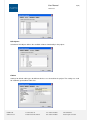
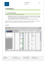
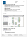
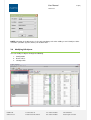
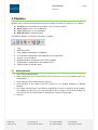
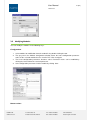
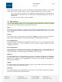
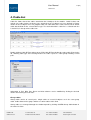
ID UM.L82344.2012
User Manual
Lonix PCT
LONIX LTD
www.lonix.com
Teollisuuskatu 33
FI-00510 Helsinki, Finland
Tel. +358 9 349 9853
Fax +358 9 349 9863
VAT 1043054-9
Trade Reg.No. 678.356
2 (42)
User Manual
Lonix PCT
Index
Lonix PCT
4
1.
Project Settings .............................................................................................................................5
2.
2.1
2.2
2.3
2.4
2.5
2.6
2.7
I/O-Objects .....................................................................................................................................7
Views to I/O-objects ........................................................................................................................7
Handling I/O-objects ........................................................................................................................9
Adding I/O-objects ...........................................................................................................................9
Modifying I/O-objects.....................................................................................................................10
Attaching I/O-objects to Module ....................................................................................................11
Edit Functions ................................................................................................................................12
Bindings .........................................................................................................................................13
3.
3.1
3.2
3.3
Modules ........................................................................................................................................14
Adding Modules .............................................................................................................................14
Modifying Modules ........................................................................................................................15
Edit Functions ................................................................................................................................16
4.
Cable List .....................................................................................................................................17
5.
Testing Table ...............................................................................................................................19
6.
6.1
6.2
Building Modeler .........................................................................................................................21
Adding a Control System ..............................................................................................................21
Adding a Control Group ................................................................................................................21
7.
7.1
7.2
7.3
Other Features .............................................................................................................................22
Creating Project Documentation ...................................................................................................22
System Templates.........................................................................................................................23
Network Connections ....................................................................................................................25
8.
8.1
8.2
8.3
8.4
8.5
8.6
8.7
8.8
8.9
8.10
8.11
Access Control ............................................................................................................................27
Adding Network Controllers ..........................................................................................................27
Adding Interface Panels ................................................................................................................28
Panel Configurations - Reader Interface, Input and Output ..........................................................29
Zones and Areas ...........................................................................................................................31
Event Configurations .....................................................................................................................32
Door Groups ..................................................................................................................................33
Schedules ......................................................................................................................................34
Access Groups ..............................................................................................................................35
Creating Access Cards..................................................................................................................35
Card Formats ................................................................................................................................36
Creating Access Database ............................................................................................................36
9.
Creating Example Project ...........................................................................................................37
LONIX LTD
www.lonix.com
Teollisuuskatu 33
FI-00510 Helsinki, Finland
Tel. +358 9 349 9853
Fax +358 9 349 9863
VAT 1043054-9
Trade Reg.No. 678.356
3 (42)
User Manual
Lonix PCT
Introduction
This document describes functionality of the Lonix Project Creation Tool (PCT). Lonix PCT is a
software tool for configuring Lonix controllers, designing connections (bindings) between I/O-objects,
performing testing, managing the project and automatically producing the project documentation. The
created project data is in COBA compatible XML format.
This document is meant primarily for system integrators and other automation system professionals.
LONIX LTD
www.lonix.com
Teollisuuskatu 33
FI-00510 Helsinki, Finland
Tel. +358 9 349 9853
Fax +358 9 349 9863
VAT 1043054-9
Trade Reg.No. 678.356
4 (42)
User Manual
Lonix PCT
Lonix PCT
Functionality Description
LONIX LTD
www.lonix.com
Teollisuuskatu 33
FI-00510 Helsinki, Finland
Project Settings
I/O Objects
Modules
Access Control
Other Features
Tel. +358 9 349 9853
Fax +358 9 349 9863
VAT 1043054-9
Trade Reg.No. 678.356
5 (42)
User Manual
Lonix PCT
1. Project Settings
Project settings are modified by creating a new project through File – New Project or modifying an
existing one through Project – Properties in the main menu. Basic information about the project is
filled in the respective fields on four different tabs as shown in the following figure:
General: Basic information about the project
Modules: Lonix controller types used in the project
I/O-objects: I/O-object types used in the project
Cables: Default settings for cable types used in the project
General:
-
Project name
Project number
Created: Date of project creation
Author: Name of the project manager
Network name: Name of the LNS network applied in the project
Modules:
Selection of the used Lonix controller types defines the hardware that is used in the project. Software
functionality is selected through selection of I/O-objects.
LONIX LTD
www.lonix.com
Teollisuuskatu 33
FI-00510 Helsinki, Finland
Tel. +358 9 349 9853
Fax +358 9 349 9863
VAT 1043054-9
Trade Reg.No. 678.356
6 (42)
User Manual
Lonix PCT
I/O-objects:
Selection of I/O-objects defines the available software functionality in the project.
Cables:
Settings for default cable types for different devices are selected for the project. The settings are used
for automatic generation of cable lists.
LONIX LTD
www.lonix.com
Teollisuuskatu 33
FI-00510 Helsinki, Finland
Tel. +358 9 349 9853
Fax +358 9 349 9863
VAT 1043054-9
Trade Reg.No. 678.356
7 (42)
User Manual
Lonix PCT
2. I/O-Objects
2.1
Views to I/O-objects
I/O-objects can be accessed through two different views.
1. List View (IO Objects list tab): All I/O-objects in the project. The list can be sorted according
to module name, position etc by clicking on the appropriate tab. By right-clicking and choosing
“Filter” it is possible to have only select IO Objects visible.
2. Process View (tab): I/O-objects in a graphical format according to the control system tree
Both views enable same actions described in this chapter. The only exception is the creation of
bindings between network variables, which is always done through the Process View.
List View:
LONIX LTD
www.lonix.com
Teollisuuskatu 33
FI-00510 Helsinki, Finland
Tel. +358 9 349 9853
Fax +358 9 349 9863
VAT 1043054-9
Trade Reg.No. 678.356
8 (42)
User Manual
Lonix PCT
The columns in the List View of I/O-objects are as follows:
Downloaded (symbol): Red color indicates that there are changes which are not downloaded
yet
Location: Physical location of the I/O-object, such as Electrical cabin 1
System: System (i.e. process) of the I/O-object, such as Air-handling unit 1
Position: Description of the I/O-object, such as TE1 outdoor temperature
I/O: Type of the I/O-object
Connector: Physical connector strip number / SW for software objects
Module: Identification of the module, which the I/O-object is attached to
Device: Type of physical field device, such as a relay
Test: Testing status radiobuttons ( not tested, not ok, ok )
Connected: Has the cable been connected into connection strips of the I/O-object
UI: Does the point show ok in the control server
Process View:
The following buttons are shortcuts to functions as follows:
1. Find
2. Add new I/O-object
3. Copy configurations from the selected I/O-object
LONIX LTD
www.lonix.com
Teollisuuskatu 33
FI-00510 Helsinki, Finland
Tel. +358 9 349 9853
Fax +358 9 349 9863
VAT 1043054-9
Trade Reg.No. 678.356
9 (42)
User Manual
Lonix PCT
4. Paste configurations from the clipboard to the selected I/O-object
5. Remove selected I/O-objects (Note: This completely removes the IO object from the project. If
you only want to remove the IO object from the current control system, then use “Select
System” instead.)
6. Download I/O-object configurations from PCT to module
7. Upload I/O-object configurations from module to PCT
2.2
Handling I/O-objects
You can select and modify I/O-objects in the following ways.
List View:
-
You can select one I/O-object by clicking the row, several I/O-objects by painting several rows
You can modify an I/O-object by double-clicking the row
Process View:
-
You can select one I/O-object by clicking the figure, several I/O-objects by painting an area
You can modify an I/O-object by double-clicking the function block
Ctrl-A selects all I/O-objects in the system.
2.3
Adding I/O-objects
You can add new I/O-objects as follows. Note! To have any functionality an IO object needs to be
mapped to a module.
1.
2.
3.
4.
5.
6.
7.
8.
LONIX LTD
www.lonix.com
Click Add New I/O-object.
Select required I/O-object type from the I/O-object list.
Select the physical location of the I/O-object from the Location list.
Select the system where the I/O-object belongs from the System list.
Select device type attached to the I/O-object.
You can make several similar I/O-objects by inserting the number of copies in the Copies field.
Click OK.
Map the IO object to a module by clicking on its Module-field. See Ch. 3.5.
Teollisuuskatu 33
FI-00510 Helsinki, Finland
Tel. +358 9 349 9853
Fax +358 9 349 9863
VAT 1043054-9
Trade Reg.No. 678.356
10 (42)
User Manual
Lonix PCT
NOTE! Selection of I/O-object type is the only mandatory task when adding a new I/O-object. Other
selections (Location, System, Device) can be done later.
2.4
Modifying I/O-objects
You can modify I/O-objects through the following.
1. Configuration
2. Netvar values
3. I/O-object info
LONIX LTD
www.lonix.com
Teollisuuskatu 33
FI-00510 Helsinki, Finland
Tel. +358 9 349 9853
Fax +358 9 349 9863
VAT 1043054-9
Trade Reg.No. 678.356
11 (42)
User Manual
Lonix PCT
Configuration:
1. Select an I/O-object for modification from the I/O-object list.
2. The grey text in the I/O-object Configuration window shows the latest configuration parameter
values of the selected I/O-object that are saved in PCT. Click Configure button. Note that when
PCT is in online mode, clicking the Configure button uploads the current configuration of the IO
object from the module to PCT.
3. The list of configuration parameters becomes active. Parameter values can be modified by
clicking the Value field of the selected parameter.
4. Save configuration parameters into the I/O-object by clicking the Save button. If PCT is in
online mode, the configuration is automatically downloaded to the IO object. Otherwise a red
downward arrow appears indicating that the configurations have not been downloaded yet.
Netvar values:
Netvar Values window shows the values of (NVI)Input and (NVO)Output variables of the selected I/Oobject. When PCT is in online mode, the values are updated automatically every few seconds.
-
The value of the NVI variable can be modified by double-clicking the Value field of the
variable. Write the new value in the text field and press ENTER to update the new value in
LON network.
-
The values of NVO variables cannot be modified.
Manual override:
Manual override can be set to some I/O-objects. When manual override is possible, the button Manual
appears in the bottom of the Netvar Values window.
Manual override is turned on by clicking the Manual button. When manual override is turned on, the
button is pushed down, the green led is lit and the text field shows the current value of manual
override. The value is changed by entering a new value to the text field and pressing ENTER. Manual
override is turned off by clicking the Manual button again. Values influenced by the manual override
are shown with orange color.
I/O-object info:
You can add comments about the object to I/O-object info. The text you enter here is shown beneath
the function block in Process View.
2.5
Attaching I/O-objects to Module
You can attach I/O-objects to modules as follows.
1. Click Module field of the I/O-object to be attached.
2. Click the button appearing on the right end of the field to open the Select Module window.
3. Select the required I/O-point of a module from the list. The list shows only currently available
attachment points for I/O-objects. You can also add new modules through the same window.
LONIX LTD
www.lonix.com
Teollisuuskatu 33
FI-00510 Helsinki, Finland
Tel. +358 9 349 9853
Fax +358 9 349 9863
VAT 1043054-9
Trade Reg.No. 678.356
12 (42)
User Manual
Lonix PCT
By default, the list shows only the modules in the same location as the I/O-object. “Show
Modules At All Locations” shows availability of modules in also other locations.
You can detach I/O-objects from modules by clicking OK when no row is selected from the list.
2.6
Edit Functions
You can do the following actions to the selected I/O-objects through Edit functions, which are available
from the main menu and by clicking the right button of the mouse.
Select
The function selects the I/O-object, i.e. updates the latest I/O-object configuration parameter values
saved in PCT into I/O-object Configuration window and shows Input and Output variable values in the
Netvar Values window.
Remove
The function removes the selected I/O-objects from the project.
NOTE! This function cannot be cancelled.
Copy Configurations
The function copies the I/O-object configuration parameter values to clipboard. These parameters can
be pasted to another I/O-object with Paste Configurations function.
Paste Configurations
The function pastes configuration parameter values from clipboard to the selected I/O-object. The
values on the clipboard must originate from the same I/O-object type, i.e. Copy-Paste function is
feasible only between two I/O-objects of the same type.
Duplicate
The function duplicates the selected I/O-objects, by creating a new I/O-object and copying the
configuration parameter values from the I/O-object to be duplicated.
Upload
The function uploads the configuration parameter values to PCT from the I/O-object of a module
attached to LON-network. The function is feasible only if the I/O-object is attached to a module.
Download
The function downloads the configuration parameter values from PCT to the I/O-object of a module
attached to LON-network. The function is feasible only if the I/O-object is attached to a module.
Select location
You can select the physical location for the I/O-object, e.g. DDC1.
LONIX LTD
www.lonix.com
Teollisuuskatu 33
FI-00510 Helsinki, Finland
Tel. +358 9 349 9853
Fax +358 9 349 9863
VAT 1043054-9
Trade Reg.No. 678.356
13 (42)
User Manual
Lonix PCT
Select system
You can select the system (i.e. process) the I/O-object is part of, e.g. Air-handling unit 1.
Select device
You can select the type of the physical field device connected to the I/O-object, e.g. relay.
2.7
Bindings
The Process View includes a list of systems, which can be each opened into a graphical view by
double-clicking. Window size can be changed with the cursor in the bottom of the system area. The
main purpose of the Process View is to design bindings between the I/O-objects.
You can create and modify bindings as follows:
1. Point an output variable (NVO) of an I/O-object. The cursor turns into a hand.
2. Click and keep the mouse button pressed down. Draw the line into the desired input variable
(NVI) of an I/O-object. Release the mouse button.
3. Modify the binding by pointing the binding line with the cursor and pressing the right button of
the mouse. Select Change Output or Change Input. Move the cursor to a new output/input and
click.
4. You can change colors of the binding lines to indicate the state of the binding:
a.
b.
c.
d.
Undefined = black
Tested = green
Working on = yellow
Internal binding = blue
5. Remove the binding by pointing the binding line with the cursor and pressing the right button
of the mouse. Select Remove.
6. Change the NVO or NVI of the binding by selecting Change Output/Change Input.
Bindings to other systems:
1. When you want to bind into I/O-objects belonging to other systems, draw the line into the box
Other Control Systems.
2. Select the target system through the Select System dialog appearing on the screen. Press
OK. The input variable information of the binding is visible in the Other Control Systems box.
3. Open the selected target system by double-clicking and continue the binding.
4. Draw binding from the output variable of the Other Control Systems box to the desired input
variable (NVI) of an I/O-object.
You can create the bindings file by selecting Tools - Create Bindings File in the main menu. PCT
creates a CSV-file with the created bindings. The CSV-file is updated in the LON database using a
network management tool’s CSV Binding plug-in.
You can move the I/O-objects in the picture by selecting them and moving them with the cursor. I/Oobjects cannot be placed on top of each other. You can create a jpg-image of each system by
pressing the right button of the mouse and selecting Create Image.
LONIX LTD
www.lonix.com
Teollisuuskatu 33
FI-00510 Helsinki, Finland
Tel. +358 9 349 9853
Fax +358 9 349 9863
VAT 1043054-9
Trade Reg.No. 678.356
14 (42)
User Manual
Lonix PCT
3. Modules
Modules tab is needed mainly during the first phases of project creation. The columns are as follows:
Location: Physical location of the module, such as Electrical cabin 1
Name: Module name, such as Module01
Type: Module type, such as Multi2242
Node ID: Module’s node ID number
The following buttons are shortcuts to functions as follows:
1.
2.
3.
4.
5.
6.
7.
8.
3.1
Find
Add new module
Copy module configurations to clipboard
Paste module configurations from clipboard to selected module
Remove selected modules
Download module configurations from PCT to module
Upload module configurations from module to PCT
Update module’s node ID number
Adding Modules
1. Click Add New Module button.
2. Write module name in the Name field. The name must be the same as the module name in the
LON database.
3. Select HW type of the module from the Type list.
4. Select location of the module from the Location list. See location definitions in Building
Modeler.
5. Tick Create I/O-objects box if you want to automatically create the I/O-objects for the module.
The program also attaches the created I/O-objects to the module. The desired I/O-object for
each I/O-type can be selected from the list below the Create I/O-objects box.
6. Click OK.
LONIX LTD
www.lonix.com
Teollisuuskatu 33
FI-00510 Helsinki, Finland
Tel. +358 9 349 9853
Fax +358 9 349 9863
VAT 1043054-9
Trade Reg.No. 678.356
15 (42)
User Manual
Lonix PCT
3.2
Modifying Modules
You can modify the modules in the following ways.
Configuration:
1. Select module for modification from the module list by double-clicking the row.
2. The grey text in the Module Configuration window shows the latest configuration parameter
values of the selected module that are saved in PCT. Click Configure.
3. The list of configuration parameters becomes active. Parameter values can be modified by
clicking the Value field of the selected parameter.
4. Save configuration parameters into the module by clicking Save.
Netvar values:
LONIX LTD
www.lonix.com
Teollisuuskatu 33
FI-00510 Helsinki, Finland
Tel. +358 9 349 9853
Fax +358 9 349 9863
VAT 1043054-9
Trade Reg.No. 678.356
16 (42)
User Manual
Lonix PCT
Netvar Values window shows the values of (NVI)Input and (NVO)Output variables of the selected
module. When PCT is in online mode, the values are updated automatically every few seconds.
-
The value of the NVI variable can be modified by double-clicking the Value field of the
variable. Write the new value in the text field and press ENTER to update the new value in
LON network.
-
The values of NVO variables cannot be modified.
3.3
Edit Functions
You can do the following actions to the selected modules through Edit functions, which are available
from the main menu and by clicking the right button of the mouse.
Select
The function selects the module, i.e. updates the latest module configuration parameter values saved
in PCT into Module Configuration window and shows Input and Output variable values in the Netvar
Values window.
Remove
The function removes selected modules from the project. NOTE! This function cannot be cancelled. IO
objects attached to the module are not removed but become unattached from any module.
Copy Configurations
The function copies to clipboard the configuration parameter values of the selected module and the
I/O-objects attached to it. These parameters can be pasted to another module with Paste
Configurations function.
Paste Configurations
The function pastes configuration parameter values from clipboard to the selected module and the
attached I/O-objects. The values on the clipboard must originate from the same module type, i.e.
Copy-Paste function is feasible only between two modules of the same type.
Duplicate
The function duplicates the selected modules, by creating a new module and copying the configuration
parameter values from the module to be duplicated. The function also duplicates the I/O-objects
attached to the module and their configuration parameter values and attaches the duplicated I/Oobjects to the new module.
Upload
The function uploads the configuration parameter values of the module and attached I/O-objects to
PCT from a module attached to LON-network.
Download
The function downloads the configuration parameter values of the module and attached I/O-objects
from PCT to a module attached to LON-network.
LONIX LTD
www.lonix.com
Teollisuuskatu 33
FI-00510 Helsinki, Finland
Tel. +358 9 349 9853
Fax +358 9 349 9863
VAT 1043054-9
Trade Reg.No. 678.356
17 (42)
User Manual
Lonix PCT
4. Cable List
Cable list shows data of the cables attached to the I/O-objects of the modules. Cable list does not
include any cables before the device type attached to the I/O-object has been defined in Device
column in the I/O-object view. The program adds new cable data to the cable view based on default
cable data defined for the selected device type. The desired location’s cable list is selected from the
Location list, in the top of the cable view.
Double-clicking Cable ID/Type column opens Edit Cable ID/Type window for setting cable ID and relay
ID, switching cable type and selecting whether the cable is part of a cable group including several
pairs.
Information in Pair, Wire, Dev, Dconn and Note columns can be modified by clicking the desired
column and entering the new value.
Group cables
Group cables consist of several pairs. Single cables of several I/O-objects are in the same group
cable. Cables between the group switches are often cables of this kind.
Group cables are managed through the window opened by clicking Add/Edit Group Cable button in
the cable List View.
LONIX LTD
www.lonix.com
Teollisuuskatu 33
FI-00510 Helsinki, Finland
Tel. +358 9 349 9853
Fax +358 9 349 9863
VAT 1043054-9
Trade Reg.No. 678.356
18 (42)
User Manual
Lonix PCT
Edit Cable ID/Type window is opened by double-clicking Cable ID/Type column on the desired cable.
The user can select whether the cable is a single cable or part of a cable group. The cable is added as
part of a cable group by selecting the desired group cable from the Group Cable list and clicking OK.
After this, the cable list shows the cable ID and cable type corresponding to the selected group cable.
The cable can be removed from the group by selecting Single Cable in the Edit Cable ID/Type
window.
LONIX LTD
www.lonix.com
Teollisuuskatu 33
FI-00510 Helsinki, Finland
Tel. +358 9 349 9853
Fax +358 9 349 9863
VAT 1043054-9
Trade Reg.No. 678.356
19 (42)
User Manual
Lonix PCT
5. Testing Table
Testing table is designed to make project testing and maintenance easier. Using testing table it is easy
to follow the progress of the project, for example: How many cables have not been connected yet? Are
all alarming points giving alarms? Has the point been connected to the control server? Etc.
Testing table is filled in during the project by ticking the tasks in the testing table columns. The table
view can be printed out as a PDF document, which can be printed on paper and given e.g. to
electricity contractor as a task list of unconnected cables.
The following information is marked by ticking the boxes or radio buttons:
Title
Description
Test
Does the point function as it should
Radio buttons from left to right: not tested, not ok, ok
Connected
Is the device attached to the point included in delivery
Has the cable been connected into connection strips of the I/O-object
Control UI
Shall the point be connected to the control server
Does the point show ok in the control server
Alarm
Does the point act as alarming point
Do the alarms function ok in the point
Note
Free text field for observations and other information
Screening (distillation) of information
Information shown in the testing table can be screened to show only the relevant parts of information
of the whole project. Screening is done per column, by clicking the column title.
LONIX LTD
www.lonix.com
Teollisuuskatu 33
FI-00510 Helsinki, Finland
Tel. +358 9 349 9853
Fax +358 9 349 9863
VAT 1043054-9
Trade Reg.No. 678.356
20 (42)
User Manual
Lonix PCT
A list is opened (circled in the figure) for selecting the screening criteria. [All] selection on top of the list
means that no screening is done. Click [Custom] selection to open Custom Search window, where the
screened information can be selected freely. For example, all positions beginning with text TE can be
found. Other choices on the list include names appearing in the column.
After selection the title background becomes yellow, which means that in that column the screening
functionality is turned on. Screening is removed by selecting [All] as screening criteria. When
screening several columns at the same time, each screening criteria remains on until it is removed.
The view shown currently on the screen can be printed out as a PDF-document by clicking Create pdfdocument from current view button above the list.
LONIX LTD
www.lonix.com
Teollisuuskatu 33
FI-00510 Helsinki, Finland
Tel. +358 9 349 9853
Fax +358 9 349 9863
VAT 1043054-9
Trade Reg.No. 678.356
21 (42)
User Manual
Lonix PCT
6. Building Modeler
Building Modeler consists of two parts:
1. Building Model describes the physical structure of the building
2. Control Model describes the system structures and locations
The following buttons are shortcuts to functions as follows:
1.
2.
3.
4.
5.
6.
Add a new building into the Building Model Tree
Add a new building part into the Building Model Tree
Add a new space into the Building Model Tree
Add a new control system into the Control Model Tree
Add a new control group into the Control Model Tree
Remove selected objects from the tree
Start by creating first a building model. By default, control systems are added to the first building.
6.1
Adding a Control System
You can add a control system by clicking the respective shortcut button or by right-clicking on a control
system in the control system tree. The created control system can also be defined to be a Location by
selecting yes in the Object Properties. This is useful for defining actual physical locations for modules
and IO objects.
6.2
Adding a Control Group
Control groups are used by the COBA server and represent a single measurement or control in the
system. With the release of COBA Editor this feature of PCT should no longer be used. All COBA
server configurations etc. should be made with COBA Editor.
LONIX LTD
www.lonix.com
Teollisuuskatu 33
FI-00510 Helsinki, Finland
Tel. +358 9 349 9853
Fax +358 9 349 9863
VAT 1043054-9
Trade Reg.No. 678.356
22 (42)
User Manual
Lonix PCT
7. Other Features
7.1
Creating Project Documentation
A PDF document can be created from a PCT project, including basic information about the project,
position list of the I/O-objects and configuration information of the modules. At document creation the
user can decide which of these will be included in the document. In addition, separate PDF documents
can be created from the cable list and the testing table.
-
The front page of the document (Project Front Page) shows project name, project number,
date of creation and name of the project manager. The information is collected from the
project settings window.
-
Position List includes the list of I/O-object positions of the project, grouped in systems. The
attachment of the I/O-object to a module and an I/O-point is shown for each I/O-object. The list
also includes the connection strip IDs of the I/O-objects, if the information is available.
Connection strip ID of programmatic I/O-objects is SW.
-
Configuration parameters and configuration parameter values of the module and the attached
I/O-objects are listed for each module in Module Configurations. The configurations of each
module and I/O-object can be restored based on this list, by configuring the modules again
manually.
-
Cable list shows the cables connected to the modules: cable types, cable names and order of
connections in the device end. Also types of the field devices and connection information can
be included in the list.
-
Testing Table includes information to facilitate the project testing.
Start creating the documents as follows:
1. Click Documentation command in Project menu.
2. Select by clicking the boxes in Included Items the information to be saved in the project
documentation. For cable list the user can also select whether the document shall include all
locations in the project or only the selected ones.
3. Enter creation date and modification date in Dates section. Creation date is saved in the
project file. The program suggests by default the current date as modification date, but that can
be changed manually.
4. Click Start.
LONIX LTD
www.lonix.com
Teollisuuskatu 33
FI-00510 Helsinki, Finland
Tel. +358 9 349 9853
Fax +358 9 349 9863
VAT 1043054-9
Trade Reg.No. 678.356
23 (42)
User Manual
Lonix PCT
NOTE!
The program creates the project documentation in the project directory, i.e. to the directory that
includes the project file (*.lxp). Therefore it is a good idea to create a designated folder for each
project.
You can change the settings of documentation (company name, logo etc) through Options – Settings
– User Info in the main menu.
7.2
System Templates
System templates are ready parts of a project, which include required I/O-objects, modules and
configuration information for implementing a specific functionality. Systems can also be easily copied
using templates inside a project e.g. when the project includes several similar ventilation appliances or
other systems.
Importing templates to project:
1. Click Import Template command in Project menu.
2. Select the desired system template in the file window and click OK. (Default directory of system
templates can be set in Directories tab, which is opened by clicking Settings command in
Options menu.)
3. Select the imported items (Imported Items in Import Template window).
4. Select the System to which the I/O-objects of the template shall be imported.
5. Select the Location to which the I/O-objects and modules of the template shall be located.
6. Write module names in Name column in Module Names table or select Automatic Naming
Enabled box, to name modules automatically according to system name.
7. Click OK.
LONIX LTD
www.lonix.com
Teollisuuskatu 33
FI-00510 Helsinki, Finland
Tel. +358 9 349 9853
Fax +358 9 349 9863
VAT 1043054-9
Trade Reg.No. 678.356
24 (42)
User Manual
Lonix PCT
Exporting a system into system template:
1.
2.
3.
4.
Click Export Template command in Project menu.
Enter the desired file name for the template into the file window. Click OK.
Select the system to be exported as a template from the System to Export as Template list.
Select Include Devices to Template box if also device information shall be saved in the
template.
5. Write a description of the template in Description field.
6. Click OK.
LONIX LTD
www.lonix.com
Teollisuuskatu 33
FI-00510 Helsinki, Finland
Tel. +358 9 349 9853
Fax +358 9 349 9863
VAT 1043054-9
Trade Reg.No. 678.356
25 (42)
User Manual
Lonix PCT
7.3
Network Connections
PCT can function either in Online or Offline mode. The functional mode can be seen in the corner of
the PCT window (down, on the right). The mode is switched by clicking the Online/Offline button
(picture of a plug) below the menu row.
-
In Online mode PCT is connected to LON network. Configuration information is fetched from
modules in the network, and new configuration values are saved in the modules in the
network.
-
Offline mode requires no connection to LON network. Configuration information of modules is
saved in a project file (lxp-file) instead of physical modules. I/O-objects and modules can be
configured in Offline mode even before the LON database exists. The project can be planned
and preliminarily configured at the office desk already before going to construction site.
Configuration information saved in Offline mode can be later downloaded to physical modules
using the Download function of PCT.
PCT can form the network connection in the following alternative ways:
1. Through LNSHMI
2. Through LNS-DDE server
You can choose the network connection and set the parameters of the network interface by clicking
Settings in Options menu.
1. LNSHMI
Network connection parameters for LNSHMI are selected as follows:
NOTE! The LNS server application must be running before switching into Online mode.
LONIX LTD
www.lonix.com
Teollisuuskatu 33
FI-00510 Helsinki, Finland
Tel. +358 9 349 9853
Fax +358 9 349 9863
VAT 1043054-9
Trade Reg.No. 678.356
26 (42)
User Manual
Lonix PCT
2. LNS-DDE
Network connection parameters for LNS-DDE are selected as follows:
-
ServiceName: Name of DDE-server (default: LNSDDE)
-
Topic: Topic-name used in DDE requests
-
Timeout: Timeout of waiting for response from DDE server. If there is no response within the time
length defined in Timeout parameter, the function is automatically cancelled.
-
NetworkName: Name of LNS database
-
Format ProgramID: Program ID of User format file, used for formatting UNVT-network variables.
NOTE!
The LNS DDE server application must be running before switching into Online mode.
LONIX LTD
www.lonix.com
Teollisuuskatu 33
FI-00510 Helsinki, Finland
Tel. +358 9 349 9853
Fax +358 9 349 9863
VAT 1043054-9
Trade Reg.No. 678.356
27 (42)
User Manual
Lonix PCT
8. Access Control
With the latest versions of Lonix PCT (since version 1.6) it is possible to configure and manage Lonix
Access Control projects. All access control configuration is done through the Security-tab.
8.1
Adding Network Controllers
Click on the leftmost Add Ctrl -button to add a new LX-SEC-V1000 Network Controller. This opens a
dialog where you can define the name and the IP for the controller, see image below.
LONIX LTD
www.lonix.com
Teollisuuskatu 33
FI-00510 Helsinki, Finland
Tel. +358 9 349 9853
Fax +358 9 349 9863
VAT 1043054-9
Trade Reg.No. 678.356
28 (42)
User Manual
Lonix PCT
8.2
Adding Interface Panels
Door/Reader Interface Panels (LX-SEC-V100), Input Monitor Interface Panels (LX-SEC-V200) and
Output Control Interface Panels (LX-SEC-V300) can be added to the database by selecting the
appropriate Network Controller and clicking the Add Panel -button above the tree structure.
This opens a dialog where you can define the type of the panel (LX-SEC-V100, LX-SEC-V200 or LXSEC-V300). You also need to define the address for the panel.
LONIX LTD
www.lonix.com
Teollisuuskatu 33
FI-00510 Helsinki, Finland
Tel. +358 9 349 9853
Fax +358 9 349 9863
VAT 1043054-9
Trade Reg.No. 678.356
29 (42)
User Manual
Lonix PCT
The address should match the address defined with the selector on the panel. Note that if the panel is
connected with the Network Controller’s B network, you need to add 16 to the address i.e. if the
address is 10 and the panel resides in the Network Controller’s B network, you need to choose 26.
When naming panels, try to be descriptive so that it is easy to know what the panel’s function is and
what devices it controls.
When a panel has been added it will show up in the tree structure.
When the panel name is clicked, it will expand and show the interfaces included for that panel.
8.3
Panel Configurations - Reader Interface, Input and Output
When selecting Door/Reader, Input or Output interface located under the selected Panel from the tree
configuration parameters of the interface can be changed by clicking the Configure –button. PCT will
upload the prevailing configuration parameter values from the Panel and shows them on the
parameter table located in the Configuration Values -panel.
Type of the Interface can be selected from the Type -drop-down menu. Configuration parameters and
their default values are changed according to the selected type.
Name of the Interface can be typed in to the Name -text field located on top of the Configuration
Values -panel. The same name is also visible in the Project –tree.
Example of configuration values of the Door/Reader interface:
LONIX LTD
www.lonix.com
Teollisuuskatu 33
FI-00510 Helsinki, Finland
Tel. +358 9 349 9853
Fax +358 9 349 9863
VAT 1043054-9
Trade Reg.No. 678.356
30 (42)
User Manual
Lonix PCT
Example of configuration values of the Input interface:
Example of configuration values of the Output interface:
LONIX LTD
www.lonix.com
Teollisuuskatu 33
FI-00510 Helsinki, Finland
Tel. +358 9 349 9853
Fax +358 9 349 9863
VAT 1043054-9
Trade Reg.No. 678.356
31 (42)
User Manual
Lonix PCT
8.4
Zones and Areas
By selecting the root of the tree structure Zones & Areas tab will be available in the main window.
Click on the Add -button to add a new zone. This will open a dialog that allows you to name it, and
then click OK. After adding zones all input and output points, readers etc. can be assigned to the
appropriate zones. The zones feature can then be used to easily control (for example,
arming/disarming) the set of objects located on the same zone.
LONIX LTD
www.lonix.com
Teollisuuskatu 33
FI-00510 Helsinki, Finland
Tel. +358 9 349 9853
Fax +358 9 349 9863
VAT 1043054-9
Trade Reg.No. 678.356
32 (42)
User Manual
Lonix PCT
8.5
Event Configurations
Event Configurations are used to create links between Input and Output Interfaces or specific system
events. With this feature it is possible to create even complex functionalities e.g. interlocking in a
flexible manner.
Event functionalities are based on events sent and received by Interfaces. Available events are
defined in the Event Configuration dialog. You can add new event by clicking Add Event –button on
the Event Configurations dialog. After adding new event it is possible to utilize it with the Interfaces by
adding the corresponding event to specific Interface from the Event Configuration panel located in the
configuration panel of the selected interface. After clicking Add Event –button on the panel Add Event
Binding dialog is shown to be able to select event, target function and action for it.
LONIX LTD
www.lonix.com
Teollisuuskatu 33
FI-00510 Helsinki, Finland
Tel. +358 9 349 9853
Fax +358 9 349 9863
VAT 1043054-9
Trade Reg.No. 678.356
33 (42)
User Manual
Lonix PCT
Event Filters are used to restrict generation of a specific event based on some defined condition. For
example, generation of Burglar Alarm Event can be restricted only to the situation when Burglar
system is activated even though status of the Interfaces associated to send that event change to
active state.
8.6
Door Groups
After adding all the Network Controllers and interface panels the access controlled doors need to be
grouped so that the access rights can be given appropriately. To add door groups select the Project object from the tree and click on the Door Groups -button on the extreme right and then on the Add button in the dialog. Give a descriptive name for the new door group and then click on OK.
To add doors to a door group select the appropriate door group and click on Select Readers -button.
This opens a list of all the readers in the database. Tick the doors that should be part of the door
group and click on OK.
LONIX LTD
www.lonix.com
Teollisuuskatu 33
FI-00510 Helsinki, Finland
Tel. +358 9 349 9853
Fax +358 9 349 9863
VAT 1043054-9
Trade Reg.No. 678.356
34 (42)
User Manual
Lonix PCT
8.7
Schedules
Time schedules for access controlled and monitoring devices can be defined by clicking on the
Schedules-button. To add new schedules click the Add-button on the left part of the dialog. Remember
to give the schedules descriptive names. To add/edit time intervals for a certain schedule select the
appropriate schedule from the Schedules-list and use the Add- and Edit-buttons on the right.
To add a time interval that is effective until the next day you need to add two separate intervals: one
that is effective until 23:59:59 the previous day and another one that starts 00:00:00 the next day.
LONIX LTD
www.lonix.com
Teollisuuskatu 33
FI-00510 Helsinki, Finland
Tel. +358 9 349 9853
Fax +358 9 349 9863
VAT 1043054-9
Trade Reg.No. 678.356
35 (42)
User Manual
Lonix PCT
8.8
Access Groups
Access groups determine the access rights of an issued access card. You can create and modify
existing access groups by clicking on the Access Groups -button. Remember to add descriptive
names for the access groups. After creating the access groups you can assign the appropriate door
groups and schedules from the Add- and Edit-buttons on the right side of the dialog.
8.9
Creating Access Cards
Creating the access cards is the last procedure in the commissioning of an access control system.
You can create a new access card by clicking on the Add Card -button at the bottom of the
Configuration tab.
LONIX LTD
www.lonix.com
Teollisuuskatu 33
FI-00510 Helsinki, Finland
Tel. +358 9 349 9853
Fax +358 9 349 9863
VAT 1043054-9
Trade Reg.No. 678.356
36 (42)
User Manual
Lonix PCT
The following steps should be followed.
1.
2.
3.
4.
Enter the card number which is printed on the access card
Add a desired or a random PIN code that is used with keypad readers
Select an appropriate access group for the card by clicking on the Select button
Enter dates to define a validity period for the access card.
If you want to create several access cards with the same details you can use the Multiple Cards
function of the dialog. Define the card number of the first access card and the total number of access
cards to be created. Make sure all the access card numbers are in sequence.
8.10 Card Formats
Before creating any cards the card format should be defined. You can do this by clicking on the
Browse…-button and choosing the appropriate card format file. Available card format files can be
found in <COBA PCT installation folder>\security\cardformats
.
8.11 Creating Access Database
All the configurations of the access control system are stored in a database by clicking on the Create
Access DB -button. This does not yet update the online system. To update the system you need to be
connected to the access control network and click on the Commit Access DB -button. All the
configurations including all the card details etc. will be stored in the LX-SEC-V1000 Network
Controller(s). Changes done are effective immediately.
LONIX LTD
www.lonix.com
Teollisuuskatu 33
FI-00510 Helsinki, Finland
Tel. +358 9 349 9853
Fax +358 9 349 9863
VAT 1043054-9
Trade Reg.No. 678.356
37 (42)
User Manual
Lonix PCT
9. Creating Example Project
This chapter shows a simple example on BMS project creation with PCT in offline mode. For more
detailed examples on configuring various BMS equipment please have a look at the example
applications in the support section of our website www.lonix.com.
1. Create a new project:
2. Select the Modules you are going to use:
3. Select the I/O-objects you are going to use:
LONIX LTD
www.lonix.com
Teollisuuskatu 33
FI-00510 Helsinki, Finland
Tel. +358 9 349 9853
Fax +358 9 349 9863
VAT 1043054-9
Trade Reg.No. 678.356
38 (42)
User Manual
Lonix PCT
4. Select default cable types for devices:
5. Create Control Systems:
1.
2.
3.
4.
LONIX LTD
www.lonix.com
Building Modeller tab - Control Model tree - Add Control System
Select Control System node from Control Model. Set Name with Object Properties editor.
Add a building to the Building Model
Create one control system that represents a DDC box in the building. Use the object
properties editor of the control system to mark it as a location in a building.
Teollisuuskatu 33
FI-00510 Helsinki, Finland
Tel. +358 9 349 9853
Fax +358 9 349 9863
VAT 1043054-9
Trade Reg.No. 678.356
39 (42)
User Manual
Lonix PCT
6. Add Modules:
1. The name of the module needs to be exactly the same as in the LON database
2. Define the type of the module. Only the types selected in the project properties are available.
3. Select a location for the module
7. Add positions and control systems for I/Os:
1. Right-click on an IO object and select “Set Position”
2. Right-click on an IO object and select “Select System”
LONIX LTD
www.lonix.com
Teollisuuskatu 33
FI-00510 Helsinki, Finland
Tel. +358 9 349 9853
Fax +358 9 349 9863
VAT 1043054-9
Trade Reg.No. 678.356
40 (42)
User Manual
Lonix PCT
8. Click Process view tab to see the process view. Double-click the FAHU1 control system:
1. Drag and drop the IO objects to appropriate places and design bindings
9. Configure the I/O-objects (double-click each object and select “Configure”):
LONIX LTD
www.lonix.com
Teollisuuskatu 33
FI-00510 Helsinki, Finland
Tel. +358 9 349 9853
Fax +358 9 349 9863
VAT 1043054-9
Trade Reg.No. 678.356
41 (42)
User Manual
Lonix PCT
10: Design the ventilation system process in the same way.
11: Create the Bindings File by right-clicking in the process view:
The result is an All_Bindings.csv file (located in the same folder as the LXP file):
LONIX LTD
www.lonix.com
Teollisuuskatu 33
FI-00510 Helsinki, Finland
Tel. +358 9 349 9853
Fax +358 9 349 9863
VAT 1043054-9
Trade Reg.No. 678.356
42 (42)
User Manual
Lonix PCT
Now you have finished the tasks in PCT in offline mode: You have created a new project, designed
the system functionality, and finished the needed configurations and bindings.
Next you’ll create the LON database, install the modules and download configurations and bindings to
modules by using PCT in online mode.
LONIX LTD
www.lonix.com
Teollisuuskatu 33
FI-00510 Helsinki, Finland
Tel. +358 9 349 9853
Fax +358 9 349 9863
VAT 1043054-9
Trade Reg.No. 678.356