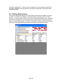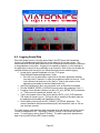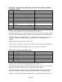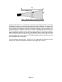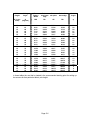
1
Viatronics Dashboard PC Application & Viatronics Speed Sensor User Manual For Pro I Stationary, Speedometer and Traffic Models Page ii Any changes or modifications not expressly approved by Viatronics Radar / Viatronics Corp., could void the user’s authority to operate the ViaRadar Speed Sensor. Viatronics Corp. Merikotkantie 10 LH 1 67200 Kokkola Finland +358 207 528 570 +358 207 528 579 www.viatronics.eu Page iii Page iv Table of Contents 1 2 3 Overview..................................................................................................................... 1 Quick Start .................................................................................................................. 2 Connecting the Speed Sensor.................................................................................... 5 3.1 Connecting to Power ......................................................................................... 5 3.2 Connecting to an RS-232 Controller ................................................................. 5 3.3 Connecting to an RS-485 Controller ................................................................. 6 3.4 Auxiliary Connections ........................................................................................ 7 4 Communicating with the Speed Sensor ..................................................................... 9 4.1 Loading the Developer’s Kit CD ........................................................................ 9 4.2 Polling for Speed Sensor ID .............................................................................. 9 4.3 Troubleshooting Communication Issues ......................................................... 10 5 Configuring the Speed Sensor ................................................................................. 12 5.1 Reading the Current Configuration .................................................................. 14 5.2 Changing and Saving the Configuration .......................................................... 15 5.3 Configuration Settings ..................................................................................... 17 5.4 Changing the Baud Rate ................................................................................. 17 5.5 Default Settings ............................................................................................... 17 5.5.1 Factory Defaults .......................................................................................... 17 5.5.2 Configuration File Defaults .......................................................................... 18 5.6 Printing Setting Values .................................................................................... 19 6 Operating the Speed Sensor .................................................................................... 20 6.1 Fork Test ......................................................................................................... 20 6.2 Demo Application Soft Keys ............................................................................ 20 6.3 Monitoring Speed Data .................................................................................... 21 6.4 Logging Speed Data ........................................................................................ 23 6.5 Monitoring the AUX Pin ................................................................................... 24 7 Upgrading Speed Sensor Software .......................................................................... 24 7.1 Checking for a new version of software .......................................................... 24 7.2 Dashboard Setup ............................................................................................ 24 8 Configuring the ViaRadar Dashboard Application ........................................................ 27 8.1 Application Control File ................................................................................... 27 8.2 Speed Sensor Configuration File .................................................................... 29 9 Custom Applications to Control Speed Sensors ....................................................... 32 10 Specifications ........................................................................................................ 34 Appendix A Streaming Speed Data Protocols.......................................... A-1 Appendix B Handshake Speed Data Protocols ........................................ B-1 Appendix C Configuration Setting Descriptions........................................ C-1 Appendix D Configuration Settings Table ................................................ D-1 Appendix E Configuration Protocol .......................................................... E-1 Appendix F Accessories ...........................................................................F-1 Appendix G Speed Sensor Installation for Lane Discrimination ............... G-1 Appendix H Speed Sensor Installation for Point-to-Multipoint Links ........ H-1 Page v 1 Overview The ViaRadar Speed Sensor is a complete Doppler Radar in a small, rugged housing. Its direction sensing capabilities and its feature-rich configuration settings allow it to filter out undesired targets and focus on your targets of interest. Depending on the model purchased, the Speed Sensor connects to the serial port on a PC or other controller via an RS-232 or RS-485 link. This interface is used to configure the unit and to monitor the speed data it sends out. The Speed Sensor can be configured to report the speeds of targets it acquires in many formats – from short ASCII character strings to larger data packets with speed and status information. The RS-232 models can stream speed data and monitor for commands from the controller at the same time. The RS-485 models only communicate one way at a time; they never stream data since they are the slave on the link. They only respond to commands and speed requests from the controller. They have the benefit of operating over longer cable distances from the controller, and also multiple Stationary RS-485 units can be installed in a point-to-multipoint configuration and controlled from a single serial port on the controller. The compact, waterproof unit can be mounted almost anywhere. Just supply 9-24 VDC power, and the Speed Sensor produces serial speed data configured for your application. The ViaRadar Pro I Stationary Speed Sensor operates from a fixed position and reports the speeds of targets moving towards and/or away from it. It can report the speed of the largest (or strongest) target it sees and a faster target at the same time. Some applications for the stationary model are speed warning signs, entrance gate security, school zone monitoring and traffic studies. It is available in RS-232 or RS-485 models. The ViaRadar Pro I Speedometer Speed Sensor mounts to a moving vehicle and reports the speed of the vehicle as it moves through its surroundings. Some uses for this model are locomotive speedometers or agricultural applications. It is available in RS- 232 or RS-485 models. The ViaRadar Pro I Traffic Speed Sensor combines the basic features of the other models for a unit that can operate in moving mode or stationary mode. Though not intended for use in enforcing speed laws, it has the features of a world-class traffic radar such as speed locking and Doppler audio output. It is only available in an RS-232 model. Page 1 2 Quick Start The easiest way to start using a Speed Sensor is to connect it to a PC using a S Speed Sensor Power/Programming Box. As shown in the pictures below, there are connections for a cable to the Speed Sensor (To RADAR), a cable to the PC (To Computer) and a power connector (9-12VDC). You’ll need: A ViaRadar Speed Sensor A PC with a serial port. For the quickest start, we recommend a PC with a standard 9-pin D serial port connector. If your PC only has USB ports, use the USB to Serial Adapter Cable listed with other accessories in Appendix F. A 12 VDC power source. If you do not have a cigarette plug power source available, use the optional AC to 12VDC Power Adaptor listed with other accessories in Appendix F. A Programming Box/Developer’s Kit. There are two kits available, one to interface with RS-232 Speed Sensors (200-0702-00) and one to interface with RS-485 models (200-0730-00). Quick Start Steps: 1. Connect the Speed Sensor to the box with the cable provided in the kit. 2. Connect to the PC using the provided serial cable. This is a “straight-through” serial cable. (Do not replace it with a “null modem” cable which will swap the Page 2 transmit and receive wires.) The box in the RS-485 kit has an internal converter, so the RS-485 signals on the Speed Sensor side are converted to RS-232 for direct connection to a PC. 3. Connect to power by plugging the cigarette plug into a 12VDC (nominal) power supply. 4. Load the Developer’s Kit CD on your PC. Insert the disc and allow the automatic installer to run to completion. You will now have a new icon on your desktop – a large red S. 5. Turn the Speed Sensor on by flipping the On/Off switch on the Programming Box. The green LED should turn on 6. Open the demo application called ViaRadar Dashboard to show the main screen below. The text in the blue title bar at the top of the screen will depend on the last used configuration file. 7. Make sure the Transmit status shows that the unit is transmitting (Transmit or Xmit). If it shows as Hold, click on the Transmit/Hold softkey to turn the radar transmitter on. Using the Mode and Zone softkeys set the Mode to Stationary and the Zone to Both to see the most targets. The Speedometer Speed Sensor does not have a stationary mode, so leave it set for Moving mode. 8. Move your hand back and forth in front of the radar lens or point the Speed Sensor toward a moving object to see speeds displayed in the windows. Targets moving directly toward or away from the radar are measured with the most accuracy. The radar can not measure the speed of objects moving across its beam at all. The Speed Sensor can pick up large and small moving objects as well as unsuspected targets such as PC fans and leaves blowing in the wind. Page 3 9. If you have a tuning fork, strike it and hold it in front of the radar lens to see its calibrated speed readout. Reading a fork works best when the Speed Sensor is in Fork Mode. If the Fork On/OFF status on the main screen shows as Off, click the soft key to toggle the fork mode to on. At power up, the Speed Sensor automatically enters Fork Mode for one minute. Since a tuning fork is not a directional target and only simulates a Doppler frequency, Fork Mode is provided to turn off the standard directionality filtering in the radar. Refer to the following sections if there are any problems in the steps above or for a more thorough description of the basic and advanced features of the Speed Sensors. Section 3 describes the physical connections of a Speed Sensor to power, to a computer or controller and to auxiliary external devices. Section 4 describes details of loading the Developer’s Kit ViaRadar Dashboard application CD and the basics of Speed Sensor communications over the controller’s serial port. Section 5 describes viewing and changing the configuration of a Speed Sensor using the demo PC application. Section 6 describes operation of a Speed Sensor using the ViaRadar Dashboard application. Section 7 describes updating the software in the Speed Sensor. Section 8 describes the control files used to configure the ViaRadar Dashboard application and how to tailor their operation to specific user needs. Section 9 describes the Speed Sensor configuration/control protocol to aid users in developing their own custom applications. Section 10 lists the Speed Sensor specifications. The appendices at the end of the manual contain detailed information for in-depth understanding of speed sensor operation. Appendix A contains detailed descriptions of the data fields in the streaming data protocols. Appendix B contains the same type of information for the handshake (polled) data protocols. Appendix C contains detailed descriptions for each of the control and configuration settings available on the speed sensors. They are arranged in groups of related function. Appendix D contains a table with all of the control and configuration settings listed by ID number. It shows which settings are available in which speed sensor model and the factory default settings for each. Appendix E contains a description of the data fields for the protocol used to control and configure speed sensors. Appendix F lists speed sensor accessories available from Viatronics. Appendix G details speed sensor installation for lane discrimination. Appendix H details speed sensor installation for point-to-multipoint links. Page 4 3 Connecting the Speed Sensor As recommended above in the Quick Start section, the fastest and easiest way to get a Speed Sensor connected and running is by using a Developer’s Kit Programming Box. In this section the simple box cabling is described in more detail along with alternative custom solutions for connections to the unit. Cables referenced below are listed in Appendix F with other optional accessories. The Speed Sensor has a single connector used to provide it power, to control and configure it and to monitor speed information. Its pinout is shown below as viewed from outside the unit. Pin 1 is between the polarizing slots, and pins 2 through 5 are numbered in a counter-clockwise direction. Pin 1 – RX – Receive Data – toward the Speed Sensor (COMM+ for RS-485 units) Pin 2 – PWR – 12VDC (nominal) Pin 3 – AUX – Auxiliary Input/Output Pin 4 – TX – Transmit Data – from the Speed Sensor (COMM- for RS-485 units) Pin 5 – GND – Ground 3.1 Connecting to Power Using the Programming Box, the power connection is made from the cigarette plug, through the box, and to pins 2 and 5 of the Speed Sensor over the 155-2223-00 Speed Sensor and Power I/O Cable. If the Speed Sensor needs to be mounted farther from the Programming Box, the optional 155-2290-00 Extension Cable is available for an extra 15 feet. For custom user cabling, connect pin 2 to a DC voltage source in the range from 9 to 16 volts. Connect pin 5 to the source’s ground return. The Speed Sensor draws less than .5 A of current at a nominal 12 VDC. NOTE: When mounting the Speed Sensor on a metal structure, electrically isolate the Speed Sensor from the metal structure. The Standard Mounting Bracket kit listed in Appendix F is supplied with nylon shoulder washers, which electrically isolate the Speed Sensor from the mounting bracket. 3.2 Connecting to an RS-232 Controller Using the RS-232 version of the Developer’s Kit, 200-0702-00, the connection between the Speed Sensor and the RS-232 PC controller runs over the 155-2223-00 Speed Sensor Power and I/O Cable, through the box, and to the controller’s 9-pin D serial port Page 5 over the 155-2130-00 RS-232 Straight-Through Cable. (Do not replace this RS-232 cable with a “null modem” cable which will swap the transmit and receive wires.) Some PCs are not configured with the recommended 9-pin D serial ports and have USB ports instead. In these cases, acquire a USB to serial port adapter to perform the necessary conversion. These products vary and may or may not work well. In some cases they provide undesirable buffering and delay, and a different brand should be used. For custom user cabling, the serial connection uses pins 1, 4 and 5 of the Speed Sensor connector. Pin 1 is the Receive Data pin for data transmitted from the controller toward the Speed Sensor. Pin 4, Transmit Data, is for data transmitted from the Speed Sensor toward the controller. Pin 5 is the common ground. Speed Sensors are configured for 10 bit asynchronous serial communications with 1 start bit, 8 data bits, 1 stop bit and no parity (8N1). This is standard for PC serial ports, but a custom controller may need to be modified to match these settings. To assist with custom cable development, the 155-2227-00 Power I/O User Cable Parts Kit can be used to interface the 155-2223-00 Power and I/O Cable to custom connections. 3.3 Connecting to an RS-485 Controller One of the benefits of the RS-485 models is distance. The Speed Sensor can be mounted farther from the controller and still work properly. The trade-off is that the connection only works in one direction at a time. The RS-232 Speed Sensors can stream speed messages on the Transmit line and at the same time receive commands from the controller on the separate Receive line. The RS-485 COMM+ and COMMlines, on the other hand, are used together as a pair for either sending messages or receiving them – but not at the same time. To prevent messages in the two directions from colliding, the RS-485 protocol requires that there be a master on one end of the link and a slave on the other. An RS-485 Speed Sensor always acts as the slave device, and the controller is always the master. The RS-485 Speed Sensors only answer commands or requests for speeds from the controller. They never send any data without receiving a request first. Another benefit of RS-485 communications that only the Stationary RS-485 model offers is that, from a single COM port, one controller can control multiple speed sensors all connected to the same pair of wires. This type of link configuration is called point-tomultipoint. For this to work, each of the speed sensors must have a unique address so that the controller can direct commands to one unit at a time or broadcast commands to all units at the same time. The address of each RS-485 unit as shipped from the factory is 2. The Stationary RS485 model can be set to a different address using Setting ID 116 and the protocol described in Section 9. Once the address is changed in this manner, the unit will retain the new address until changed using the same method. A hard reset of the unit or loading a new version of software changes other configuration settings to the factory defaults, but the unit’s address does not change. Page 6 Using the RS-485 version of the Developer’s Kit, 200-0730-00, the connection between the Speed Sensor and the RS-232 PC controller runs over the 155-2239-02 Speed Sensor Power and I/O Cable, through the box where the data signals are converted from RS-485 to RS-232, and to the PC controller’s 9-pin D serial port over the 155-2130-00 RS-232 Straight-Through Cable. (Do not replace this RS-232 cable with a “null modem” cable which will swap the transmit and receive wires.) Some PCs are not configured with the recommended 9-pin D serial ports and have USB ports instead. In these cases, acquire a USB to serial port adapter to perform the necessary conversion. These products vary and may or may not work well. In some cases they provide undesirable buffering and delay, and a different brand should be used. The USB to Serial Adapter Cable listed in Appendix F is available from Viatronics. For custom user cabling to RS-485 controllers, the serial connection uses pins 1 and 4 of the Speed Sensor connector. These signals, COMM+ and COMM-, are used as a pair for either transmitting or receiving data messages. No ground wire is needed for RS-485 communication. Speed Sensors are configured for 10 bit asynchronous serial communications with 1 start bit, 8 data bits, 1 stop bit and no parity (8N1). This is standard for PC serial ports, but a custom controller may need to be modified to match these settings. To assist with custom cable development, the optional 155-2239-00 RS-485 Speed Sensor Cable connects to the unit and has loose wires on the far end to interface to custom connections. 3.4 Auxiliary Connections The Aux I/O jack on the side of the Programming Box provides access to the AUX pin (pin 3) on the Speed Sensor connector. During standard use of the Speed Sensor, the AUX pin is an output from the unit. It can be configured as a Speed Alarm or to send out Pulse-Width Modulated (PWM) audio. It can also be set to no output. Refer to Section 6.5 for more information on configuring and monitoring the AUX pin. Using a standard audio plug in the jack on the Programming Box, the AUX signal is available on the tip conductor, and Ground is on the ring conductor. Although the Aux signal in the Speed Sensor is protected from static electricity (ESD), a system designer integrating the Speed Sensor into a custom design should still take proper ESD precautions into account in their design. The Aux signal should also be allowed to be pulled high upon applying power to the Sensor or it may go into programming mode and have all the user settings reset to factory defaults. As a Speed Alarm, the AUX pin outputs a simple logic level signal (3.3V for alarm condition or 0V for no alarm) and can drive a maximum of 10mA. For audio, the AUX pin output is a 3.3 Vpp pulse-width modulated (PWM) audio output signal. A system integrator must provide external filtering and PWM amplifier circuitry for best audio quality. Page 7 Pressing the red Reset button on the Programming Box shorts the AUX pin to ground. It is not used during normal operation, but it can be used to force a Speed Sensor’s settings back to factory defaults as described in the Factory Defaults section (5.4.1) Page 8 4 Communicating with the Speed Sensor 4.1 Loading the Developer’s Kit CD Insert the Developer’s Kit CD in your PC, and the automatic installer should begin within a few seconds. Allow the install to complete normally by clicking on the prompts for default installation. The process installs the following items on your PC under C:\Program Files\Viaradar: ViaRadar Dashboard application that can be used to configure, monitor and control Speed Sensors. A .pdf version of this manual. Specifications for each of the Speed Sensor models. Configuration files for each of the models. Cable drawings for reference. The installation process also creates a shortcut icon on the desktop for the Dashboard application. And several shortcuts to the installed items are created under the ViaRadar tab in the Windows Start Menu. 4.2 Polling for Speed Sensor ID After turning on the Speed Sensor with the switch on the interface box, double-click the ViaRadar Dashboard desktop icon to start the demo application. The main screen below appears. Place the mouse pointer over the Viatronics logo and a rollover pop up message displays the version of code loaded in the Speed Sensor (e.g. Stationary 232 Ver:2.0.0.0). The display of this version is assurance that the unit is powered and cmmunicating since the application must poll it to find out this information. Page 9 4.3 Troubleshooting Communication Issues If the version is blank when the Speed Sensor is polled as above, the unit is not communicating with the PC. The problem could be a power problem with the Speed Sensor or a communication link problem between the PC and Speed Sensor. For suspected communication link problems or to change the serial port or the baud rate, click on “Options” in the main screen and select “Change Serial Port Settings” from the pull-down menu. Change the Port setting to match the PC’s serial port being used by the Dashboard application and the Baud rate to match the baud rate setting in the Sensor. If there is still no luck communicating with the unit, there is a way to force the Speed Sensor to a known setting. To change it to its factory default 9600 baud setting, perform the sequence outlined in the Factory Defaults section in the next chapter. Be careful using this method because all of the Speed Sensor’s settings are changed back to factory defaults – not just the baud rate. If other settings were configured for a custom application, they will need to be set again. For suspected power issues, check the power source and cabling. If the green LED on the Programming Box does not turn on when the switch is turned on, the box is not getting power. Make sure the power source is on and has a good connection to the box. Page 10 The cigarette plug has an internal fuse that can be checked. Unscrew the knurled knob on the nose of the plug to access the fuse. Replace it with one of the same size and ratings if it is blown. If the green LED does come on, power is making it to the box but maybe not to the Speed Sensor. Unscrew the Speed Sensor Power and I/O Cable from the unit and measure for proper voltage (9-16 VDC) between pins 2 and 5 on the cable. Page 11 5 Configuring the Speed Sensor When viewing the main screen of the demo application, the name of a configuration file is displayed in the title bar (e.g. [Configure Stationary 232 2.0.0.cfg]). This file defines all of the configurable settings that are available on a particular model of Speed Sensor. Since features and settings are added and changed in different versions of software, the filename also includes the version (2.0.0) that the file’s settings apply to. The screen-shot examples in this chapter are taken from the ViaRadar Dashboard application. All of the configuration features and capabilities, except software upgrading, are also available with the ViaRadar Pro I S3-Speed Sensor PC Apps located on the Program CD. If the filename is for a different unit, open a list of other available configuration files by selecting “Select New Startup Config File” from the Config pull-down menu. The dialog box on the next page will open and allow for a selection to be made. It is important that the model and software version in the configuration filename match the model and version in the Product ID. The dialog box will contain the Sensor model and current software revision in the blue title bar. Page 12 If there are no .cfg files in the list, make sure the “Look in” window is set for the Configuration Utilities folder under C:\Program Files\Viaradar – the standard installation location for these files. If the correct file is still unavailable, a lower version number for that model will work, but it may not provide access to newer features. The matching configuration file is always available from Viatronics. Contact us so we can send it to you. Page 13 5.1 Reading the Current Configuration From the Config pull-down menu, select “Edit Firmware Values”. The application will poll the Speed Sensor to read all the settings defined in the configuration file and then display the Configuration window below. The settings are grouped by type and the different types can be selected by clicking on the appropriate tab. More tabs can be made visible by clicking on the left and right arrows next to the last tab on the right. Page 14 5.2 Changing and Saving the Configuration The settings in the Speed Sensor can be changed by selecting other values from the settings’ pull-down menus as shown below, for example, changing the units from MPH to km/H (Kilometers per Hour). Click the Options Menu and select the Upload Proposed Values to Sensor to save the settings changes to the Speed Sensor. The changes can be confirmed by observing that the Sensor Values are now equal to the Proposed Values. When Upload Proposed Values to Sensor button is clicked, the ViaRadar Dashboard application sends separate commands to the Speed Sensor to set each value. The Speed Sensor responds to each command with its new or current setting value. The new settings are stored in the Speed Sensor’s internal memory and are remembered even when the unit is turned off and back on. If the Speed Sensor responds to the application with a value different from the desired value, an error may be seen as shown below. This example shows many errors due to the fact the unit was turned off. Page 15 This warning can be caused by a number of reasons. 1. If the application tries to change a setting that is not defined for a particular model or version, the Speed Sensor returns the value “255” meaning that it does not understand the request. Make sure the application is using the correct configuration file and that all settings in the configuration file are applicable to that Speed Sensor model. 2. If an illegal value is sent to the Speed Sensor, it ignores it and responds with a legal value. 3. Some settings require the internal state machine of the Speed Sensor to run before the setting is actually changed. The Speed Sensor can respond to the application’s command message before the state machine has run, so the initial response may not be the desired setting. Re-open the Configurations window after the warning to verify that the setting did actually change. These settings are Mode, Zone, Transmitter Control, Strong Lock, Fast Lock, Test and Fork Enable. 4. Some settings are read-only settings, and the Speed Sensor will respond with its internal value regardless of what value was requested. These settings are Get Product ID and Get Current AGC Gain. Refer to the end of the Speed Sensor Configuration File section for details on controlling warnings caused by these settings. Page 16 5.3 Configuration Settings There are many Speed Sensor configuration settings. Some apply to all Speed Sensors but others are specific to certain models. All settings for all models are described in detail in Appendix C where they are organized in the following groups of related function: 1. Basic Configuration 2. Serial Port Configuration 3. Target Recognition 4. Target Filtering 5. Speed Presentation 6. Locking Targets 7. Speed Alarm 8. Audio 9. TX Power Save 10. Testing 11. System In Appendix D, all settings are listed in the order of their ID number. The table there shows all available values for each setting and the factory default value for each model of Speed Sensor it applies to. 5.4 Changing the Baud Rate Since the baud rate of the Speed Sensor and the baud rate of the Dashboard application must be the same for communications to work, use the following steps to change the baud rate. 1. Open the Config Settings grid as described above and click on the Serial Port Configuration tab to see the serial port settings. 2. Change the baud rate to the new desired value and save the setting. At this point the Speed Sensor and the Dashboard application are still communicating with the previous baud rate; the baud rate of the Speed Sensor has not changed yet. 3. Turn the Speed Sensor off and back on to complete the baud rate change in the unit. 4. Configure the Scoreboard application’s baud rate to the new desired value as described in Section 4.3 above. You may need to close and reopen the application to complete the process. 5.5 Default Settings There are two types of default values for the Speed Sensors. Factory defaults are hardcoded into the unit and can not be modified. Configuration File defaults are saved in the configuration files discussed above. They can be changed in the file and saved for custom user default values. 5.5.1 Factory Defaults The factory defaults for each setting and each product are listed in Appendix D. To return all values to their factory defaults, perform the following sequence: Turn the Speed Sensor off using the switch on the Programming Box. Press and hold the red Reset button on the box (or ground the AUX pin) while turning the unit back on. Release the red button after 2 or 3 seconds. Page 17 Turn the unit off briefly and then back on again. Be careful using this method because all of the Speed Sensor’s settings are changed back to factory defaults. If other settings had been configured for a custom application, they will need to be set again. 5.5.2 Configuration File Defaults To configure the Speed Sensor with the default values in the currently selected configuration file, select the “Initialize Radar With Config File Defaults” from the Config pull down menu. Make sure that the desired configuration file is selected (as described in the beginning of Section 5) before initializing with defaults. The default values in the standard configuration files available from Viatronics are equal to the factory defaults listed in Appendix D. If changes are made to values for a custom configuration, they may be saved as default values in a new configuration file for later use. Once all changes are made, select “Save Sensor Values To New File As Defaults” from the Options pull-down menu. Save the new configuration file with a name describing the custom application. The next time “Select New Startup Config File” is selected from the Options pull-down, the new Page 18 file will be available also. If the box above is checked for “Save As Startup Config File”, the newly created file name will appear in the title bar and that file is then used for the configuration tasks. 5.6 Printing Setting Values The current configuration settings in a Speed Sensor can easily be printed for a record of values. A preview of the pages to be printed can be selected by clicking on “Print Preview”. To print the pages, select “Print” from the Options pull-down menu. A Windows Print screen will appear for you to select a printer to print the file to. Select the desired printer or use the default printer. The table of configuration values will print with a header at the top of each page that shows the date, Sensor type, and software version. Page 19 6 Operating the Speed Sensor 6.1 Fork Test A Fork Test can be run to ensure proper operation of a Speed Sensor radar. Tuning forks are calibrated to ring at a certain frequency that simulates a Doppler return from a moving object. Since they are not truly directional signals and since the radar normally filters out non-directional signals, a “fork mode” is provided to easily read tuning forks. When the Fork Mode status on the demo application’s main screen is On, strike a fork and hold it in front of the radar’s lens to see its calibrated speed readout in the target window. If the speed stamped on the tuning fork matches the speed displayed, the radar is seeing targets and reporting them properly. Fork Mode is automatically turned on for one minute when the Speed Sensor is powered up. This allows a quick fork test before the mode is automatically turned off and the radar again processes only directional targets. If a longer fork period is desired, turn on fork mode using the Fork Enable configuration setting (setting 47). When enabled in this manner, fork mode stays on for 10 minutes before it automatically turns off again. 6.2 Demo Application Soft Keys When using the ViaRadar Dashboard application to communicate with the unit, several softkeys are available for configuration and control of the unit: Fork On/OFF – Toggles the fork mode on and off. Used when testing with a tuning fork. Mode – clicking this button alternates the mode of the unit between Stationary and Moving. This capability is only available in the Traffic Speed Sensor which has both modes of operation. Page 20 Units – Selects the type of units that the Sensor will output and be displayed in the speed windows. Transmit/Hold – clicking this button turns on and off the radar transmitter. The status displays as Transmit or Hold. Zone – When in Stationary mode, clicking this button cycles through the Away, Closing and Both zones. When in Moving mode, it alternates the zone between Same lane and Opposite lane. Locking Speeds – Though not shown as a soft key, a Strong target or Fast target speed can be locked by clicking the window showing the desired speed to be locked. The locked speed will be shown in the Lock window. To clear the locked speed, click the Lock speed window. 6.3 Monitoring Speed Data The radar transmitter must be on for the Speed Sensor to register speeds. The unit will get warm to the touch when the transmitter is on for long periods, but this is normal and no cause for alarm. The demo PC application can be used to monitor speeds that the Speed Sensor detects. Other equipment or applications can also monitor the speed data from the unit by decoding the messages it transmits over the serial link. Several message formats are available and can be selected. Refer to Appendix A and Appendix B for the content and organization of the fields for the different formats. They vary from simple ASCII character strings to longer formats reporting multiple speeds and status information. There are streaming formats and polling formats. The RS-232 models can stream data in any format except EE which is reserved as a polling-only format. Whenever the radar transmitter is on, the Speed Sensor streams out speed messages in the selected message format at a fixed number of messages each second. The RS-232 models can also communicate using the Format EE handshaking (or polling) method. Instead of automatically streaming data out, it sends a single Format EE speed message packet only when the controller asks for one. The Stationary Speed Sensor reports the strong target speed value, and the Speedometer and Traffic Speed Sensors report the vehicle speed value. To enable Format EE polling, make sure the radar transmitter is on and that the Message Format is configured for EE. Then select “Start EE Polling” from the Options pull-down menu on the main screen as shown below. The Dashboard application will then begin sending EE Format Requests and displaying the values returned from the Speed Sensor. To stop the polling from the application, select “Stop Polling” from the same menu. Page 21 The RS-485 models can only use handshaking methods since they are always a slave on the link. They never send data unless the controller asks for it. They can communicate using Format EE polling as described above, but only if the unit’s address is 2, the factory default. Refer to Section 3.3 for more detail describing how to check or set the Speed Sensor address. The Stationary RS-485 model can also use the more flexible EA polling. With this method, the controller sends an EA request as described in Appendix B, and the Speed Sensor returns a single message of whatever Serial Port Output Format is selected. Since the EA request has address fields, the controller can poll any individual unit on a point-to-multipoint link and get back a speed report from only that unit. The Dashboard application does not support EA polling. A custom application as described in Section 9 is required to make use of this feature. The Dashboard application displays the speeds it receives in the appropriate speed windows. For a Stationary Speed Sensor, the strongest target the radar sees shows in the STRONG window. If a faster, weaker signal is detected, it shows in the FAST window. And if either a strong or fast target is locked, that speed shows in the LOCK window. A Traffic Speed Sensor displays all of these speeds plus the vehicle speed in the VEHICLE SPEED window. The Speedometer Speed Sensor only reports vehicle speed which displays in the VEHICLE SPEED window. In the example below, a Stationary Speed Sensor is reporting a strong target speed of 25 MPH and a faster target speed (which has been locked) of 40 MPH. Note the arrows above the speed windows. The down arrows signify that the targets are approaching the radar (closing speeds). Up arrows signify targets moving away (away speeds). Page 22 6.4 Logging Speed Data When the Speed Sensor is sending speed data in the EE Format (the handshake protocol), the Dashboard application can log the data to a file for later review. This comma-delimited file lists each speed entry with a timestamp and can easily be imported to a spreadsheet or text editor. Logging is not enabled by default, so a few settings in the application’s control file are necessary to get it started. Refer to the next chapter for complete details of this control file, but follow the steps below to enable logging: Locate the file named Dashboard.ini in the “C:\Program Files\ViaRadar\Dashboard\Application” folder. If the file is not in that location, right click on the demo application desktop icon and select “Properties” to open the properties window for the icon. Click on the Shortcut tab and look in the “Start in:” field for the location of the application executable file and the Dashboard.ini file. Open the Dashboard.ini file in any text editor such as WordPad or Notepad. Find the ENABLE_SPEED_LOGGING line and ensure the parameter is set =1. If logging of zero speeds is desired, set the LOG_ALL_SPEED_DATA parameter =1. If only non-zero speeds are desired, set it =0. Type in the desired name of the log file after the DATA_LOG_FILE parameter. The default is Speed Log.csv. The log file will be created in the same folder as the application executable and Dashboard.ini files. Set the polling interval with the EE_FORMAT_INTERVAL parameter. The number represents milliseconds between polls, and the default value is 100 ms (ten times per second). To initiate logging, make sure the radar transmitter is on and that the Serial Port Output Format is configured for EE. Then select “Start EE Polling” in the Actions pull-down menu. To stop logging, select “Stop EE Polling”. The demo application appends new data to the log each time the EE Format is started. Page 23 6.5 Monitoring the AUX Pin Using configuration setting 16, the AUX pin on the Speed Sensor connector can be configured to provide Doppler audio for targets (in PWM format), a speed alarm signal, or it may be disabled completely. Refer to Section 3.4 (Auxiliary Connections) for connection location and other requirements. When used as a speed alarm, the AUX pin is grounded by the Speed Sensor when target speeds are below the Alarm Speed Threshold, set using setting 12. When the target speed is equal to or greater than the threshold, the AUX pin is set to 3.3VDC. The output of the Aux pin is limited to a maximum of 10mA. A buffer circuit is required to drive a mechanical relay or some other external warning device. A 3.3 Vpp pulse-width modulated (PWM) audio output signal is provided for Doppler audio and status beeps – and must be filtered and amplified for best audio quality. Speed alarm & audio are only available on Stationary and Traffic Speed Sensor models. 7 Upgrading Speed Sensor Software The Dashboard program has the unique ability of uploading new software to Speed Sensors with version 2.0.0 or later code already installed. If your Speed Sensor has software that is earlier than 2.0.0, other PC Applications located on the Program CD can be used for communicating to the Speed Sensor. Check with the factory to determine if version 2.0.0 is available for your type of Speed Sensor. If software version 2.0.0 is available, the Sensor can also be sent to the factory for upgrading to the latest program. This section details the process of uploading a new software program to your Speed Sensor 7.1 Checking for a new version of software Contact the Customer Service Department at Viatronics and inquire about a new version of software. Please have your current version available when asked so it can be determined if there is a new load for your Sensor. A new version can be sent by email and will install on your hard drive under C:\Program Files\Viaradar\.... in a sub folder that groups the different versions together 7.2 Dashboard Setup Once the new code has been saved to your hard disk, open the Dashboard program. Click on the “Options” menu and then click on “Reprogram Radar”. A new window will appear as seen below. Follow the instructions to determine which type of Sensor you have. Click on the appropriate selection box for your radar in the upper right corner of the screen. Click on “OK” to proceed. Page 24 VIATRONICS CORP. VIARADASPEED SENSOR 34.7 GHZ S.N. SU001422 Another window will open to show the available files that can be uploaded to the sensor. Select the program that is to be uploaded to the unit, in this case “s3_sta_200.p” located under the ViaRadar S3 Stationary section, see picture below. In this example, this program is the latest version available for the Stationary type of Sensor. The folder structure may vary by system. Double click on the icon of the desired version and click on “Ok” on the popup window. The program will start to upload the code and a progress meter will show at the bottom of the window. Programs for the RS485 versions of the Speed Sensor will have the number “4” in the filename just before the revision number, e.g. “s3_sta4_200.p”. Page 25 When the upload is complete, another popup window will appear to announce a successful upload. One of the other types of Sensors, Speedometer or Traffic, may be installed in the Sensor as well but the proper configuration file will need to be applied for proper operation. If the configuration is incorrect for the program just uploaded, a warning screen will appear and allow you to browse for an appropriate configuration. Page 26 8 Configuring the ViaRadar Dashboard Application The ViaRadar Dashboard application for communicating with and configuring Speed Sensors consists of a set of files which reside on the PC. The Developer’s Kit CD provided with the Speed Sensor Programming Box Kits installs all of the files listed below (in italics) on the user’s PC under the C:\Program Files\ViaRadar folder. ViaRadar Dashboard.exe is the PC demo application executable file used to control and communicate with the Speed Sensors. Dashboard.ini is the control file for the demo application. These two files are installed in the C:\Program Files\ViaRadar\Dashboard\Application folder. The executable file and the Dashboard.ini control file are used as a pair when the application is running. The executable file reads parameters from the control file during initialization. And the executable file also updates the control file during operation. For this reason, only one executable file in a folder should be run at a time. If more than one executable is running and trying to use the same Dashboard.ini file, the executables will interfere with each other. It is possible to run more than one application at a time on one PC if, for example, there is another Speed Sensor connected to different serial port. Simply copy the executable file and the Dashboard.ini file to a different folder where they can run without interference. There are also unique standard configuration files for each model and software version of Speed Sensor: Configure Traffic 232 x.x.x.cfg is for a Traffic Speed Sensor version x.x.x. Configure Stationary 232 x.x.x.cfg is for an RS-232 Stationary Speed Sensor. Configure Stationary 485 x.x.x.cfg is for an RS-485 Stationary Speed Sensor. Configure Speedometer 232 x.x.x.cfg is for an RS-232 Speedometer Speed Sensor. Configure Speedometer 485 x.x.x.cfg is for an RS-485 Speedometer Speed Sensor. These files are installed in the C:\Program Files\Viaradar\Configuration Utilities folder. 8.1 Application Control File The control file, Dashboard.ini, is an ASCII text file that may be edited with any text editor such as WordPad or Notepad. It has several control parameters that can be changed to affect the operation of the Speed Sensor application. See a copy of the file below with explanations of the parameters following. [Viaradar] PORT=COM1 BAUD=9600 SOURCE_ID=1 DESTINATION_ID=2 CONFIG_FILE=C:\Program Files\Viaradar\Configuration Utilities \Configure Stationary 232 2.0.0.cfg CONFIG_FILE_LOCATION=C:\Program Files\Viaradar\Configuration Utilities GET_CFG_INTERVAL=5000 Page 27 RESPONSE_TIMEOUT=500 RETRY=2 EE_FORMAT_INTERVAL=100 ENABLE_SPEED_LOGGING=1 LOG_ALL_SPEED_DATA=0 DATA_LOG_FILE=Speed Log.csv PORT defines the PC serial port used for communication with the Speed Sensor. When the serial port is changed using the Options pull-down “Change Serial Port Settings” function, this parameter in the Dashboard.ini file is automatically changed. It can also be changed by editing the file. After the COM port is changed, the application needs to be closed and re-opened for the newly selected port to be used. BAUD defines the baud rate to be used for communication with the Speed Sensor. As with PORT above, this parameter can also be changed via the Options pull-down “Change Serial Port Settings” function or by editing the file. And after changing the baud rate, the application needs to be closed and re-opened for the setting to take effect. SOURCE_ID is always set to 1 and DESTINATION_ID is always set to 2. When communicating with a Speed Sensor, the application is always the master of the link (ID 1) and the Speed Sensor is always the slave (ID 2). Do not change these values. CONFIG_FILE defines the Speed Sensor configuration file used during a session, and CONFIG_FILE_LOCATION defines the path to that file. These parameters are updated by the application when “Select New Startup Config File” is selected from the Config pull-down menu. The content of configuration files is discussed in detail in the next section. GET_CFG_INTERVAL defines how often (in milliseconds) the application polls the Speed Sensor to update the status fields in the main window. This parameter applies to the status fields only (Units, Mode, Zone…) – not the speed windows. The default is 5000 ms (5 seconds). This parameter value can be increased to reduce the message traffic on the link. RESPONSE_TIMEOUT is the time in milliseconds that the application will wait for a response from the Speed Sensor before a retry or failure. The default is 500 ms (½ second). RETRY defines the number of times the application will resend a configuration setting to the Speed Sensor if it doesn’t get a response. EE_FORMAT_INTERVAL defines how often (in milliseconds) the application polls the Speed Sensor for a speed report in EE Format. Polling begins after selecting “Start EE Polling” from the Actions pull-down menu, and polling stops after selecting “Stop EE Polling”. The default value is 100 ms (1/10 second or 10 times per second). The value can be increased or decreased to speed up or slow down the rate of EE Format polling. ENABLE_SPEED_LOGGING defines whether a speed log file is generated for the current session. Logging is enabled when the parameter is set =1 and disabled when set =0. Logging only takes place if the Speed Sensor’s Serial Port Data Format is set for EE Format. LOG_ALL_SPEED_DATA is used to inhibit logging 0 speeds. When set =1 all speeds are logged including 0 speeds. When set =0 only speeds above 0 are logged, and the length of the log file is reduced. Page 28 DATA_LOG_FILE defines the filename for the speed log. This file will be saved in the directory where the application file and the Dashboard.ini file reside. 8.2 Speed Sensor Configuration File The Speed Sensor configuration files are also ASCII files which can be edited with a text editor. Viatronics provides a different file for each different model of Speed Sensor and for each different software version for each model. These standard configuration files define the settings from Appendix D that the application can control in a unit. A short portion of a configuration file is shown below. Note that the file is organized in a series of text blocks: three blocks in the example below. The order of the blocks in the .cfg file determines the order in which the settings and their values will be displayed in the Configuration window. As long as the blocks are moved as units, they can be arranged in any order. Blocks for the settings used most often could be placed at the top of the section so their values appear at the top of the Configurations window. Blocks for settings that are never used could even be deleted from the file to speed up the “Edit Firmware Values” process. We recommend copying the standard file provided by Viatronics to a file with a new name before making changes. In that way, many custom configuration files can be created for different uses, and the standard file is always available to fall back on for complete control. Page 29 Each block represents a different configuration setting and has the following format: [Transmitter Control] PACKET_TYPE=1 COMMAND_ID=42 ANTENNA_NUMBER=1 VALUE_BYTES=1 DATA_TYPE=1 VALUE_MIN= VALUE_MAX= VALUE_ITEMS_DISPLAY=Hold,Transmit VALUE_ITEMS_FIRMWARE=0,1 DEFAULT_VALUE=1 DISPLAY=1 The first line in the block defines the name of the setting in brackets. This is the setting description that displays in the left column of the Configurations screen, and it can be changed to any name desired. PACKET_TYPE should be set =1. Do not change this value. It is used in the Packet Type field of the Configuration Protocol described in Appendix E when the application is building commands to send to the Speed Sensor. COMMAND_ID is the Setting ID (in decimal format) from Appendix D that corresponds to the setting description. ANTENNA_NUMBER should be set =1. Do not change this value. It is used in the Antenna Number field of the Configuration Protocol described in Appendix E when the application is building commands to send to the Speed Sensor. VALUE_BYTES is the number of bytes that the setting value uses. Do not change this value from the value provided in the standard configuration files from Viatronics. DATA_TYPE controls the behavior of the value fields. When set = 1 (list type), only the values listed in VALUE_ITEMS_DISPLAY are valid. When set = 2 (free-form numeric type), in addition to the values in the list (if any), the user can also enter any numeric value in the range from VALUE_MIN through VALUE_MAX. VALUE_MIN defines the minimum acceptable value when DATA_TYPE=2. VALUE_MAX defines the maximum acceptable value when DATA_TYPE=2. VALUE_ITEMS_DISPLAY defines the text that will appear as pull-down selections in the row for a given setting in the Configurations window. The values are separated by commas with no spaces and may be set to any desired text. VALUE_ITEMS_FIRMWARE defines the actual values the application uses to communicate with the Speed Sensor. These values are also separated by commas, and the order correlates on a one to one basis with the order of the list for VALUE_ITEMS_DISPLAY. The available values for each setting are defined in Appendices C and D. DEFAULT_VALUE is the default value described in the Configuration File Defaults section. It may be set to any legal value for the setting – either from the VALUE_ITEMS_FIRMWARE list or between VALUE_MIN and VALUE_MAX. DISPLAY defines whether the setting is displayed in the Configurations screen. When set =1, the setting is displayed. When set =0, the setting is not displayed. This method can be used to skip displaying settings of no interest without having to delete the whole block from the file. For most commands, the Speed Sensor is able to change the setting and report the new, desired value. However, some settings are only used for polling or monitoring the status of the unit and cannot actually change the setting in the unit. For these read-only Page 30 settings, the Speed Sensor still sends a response, but it responds with the internal setting value and may result in the application program displaying the following screen. These settings are #37 Get Product ID and #50 Get Current AGC Gain. Ensure that the DISPLAY parameter for these settings = 0 so that the application will not try to change them and generate a warning. Choose Continue to finish the operation but make the necessary change to the configuration file to prevent the warning from appearing again. Page 31 9 Custom Applications to Control Speed Sensors This chapter discusses in detail the protocol used to communicate with the Speed Sensors. It is the protocol used by the demo application described earlier in this manual and can be used by designers to develop custom applications to control Speed Sensors. A basic knowledge of hexadecimal math is required, but the protocol fields are basically “fill in the blank”. Using the configuration protocol described in Appendix E, a designer can “get” the current value of a setting from the unit, “set” the setting to a new value or “change (increment)” the value. When a PC or other controller sends a configuration command packet to the Speed Sensor, the Speed Sensor responds immediately with a packet in the same format. The only values changed in the returned packet are the Destination ID, Source ID, Configuration Value and the Checksum bytes. The Payload Length may also change depending on the length of the returned Configuration Value. The PC or controller is always defined to be the master (ID = 0x01) so commands from the controller will always have 0x01 as the Source ID, and responses from speed sensors will always have 0x01 as the Destination ID. The ID for all RS-232 units is 0x02 and can not be changed since there can only be a single Speed Sensor on the RS-232 link. Multiple Stationary RS-485 units can work simultaneously on a single link to the controller in a point-to-multipoint configuration. The ID of each one must be unique and in the range of 2-254 (0x02 – 0xFE). ID 0 is undefined and should not be used. ID 255 (0xFF) is the broadcast address. Every unit on the link acts on commands sent to ID 255, so a controller can, for example, turn all the radar transmitters on or off with a single command. Be aware that each unit also sends a response packet to a broadcast command, and that the responses are likely to be garbled on the shared link. For this reason, always disregard responses to broadcast commands unless there is only one Speed Sensor on the link. If the response from a single unit on a multipoint link is desired, always address that unit in the command. Another good use for a broadcast command is to find out the ID of a Stationary RS-485 Speed Sensor that may not be responding to its expected address. Make sure the unit is the only one on the link, and send the Get Speed Sensor Address command (116) to the broadcast Destination ID 255 (0xFF). As long as the baud rate is correct, the unit will respond back using its ID as the Source ID in the response packet. All of the configuration methods (get, change and set) use the same packet format defined in Appendix E. The differences are in the use of the Command ID and the Configuration Value fields. The “change” command and the “get” command are similar in that the Command ID field is set equal to the Setting ID (in hex) from the list of settings in Appendix D. o For a “change” command, the Configuration Value is set to 1 to instruct the Speed Sensor to increment the value by 1 and return it: change(1). If the incremented value exceeds the legal range for the setting, the value rolls around to the lowest value in the range. Page 32 For a “get” command, the Configuration Value is set to 0 basically instructing the Speed Sensor not to increment the current value but to simply return it. This is essentially a change(0) command. For a “set” command, the Command ID field is set equal to 0x80 plus the Setting ID value (in hex) from the list in Appendix D (essentially turning on the high-order bit). The Configuration Value field is set to the new desired value. o In the response packet, the Speed Sensor inserts the value of the requested setting in the Configuration Value field. Note that all commands from the controller may not be answered with the requested value on the first attempt. The Speed Sensor may respond before the requested action has had time to happen. In cases where the Speed Sensor can make the change immediately, the returned value will be the requested value. In other cases where the internal state machine of the Speed Sensor must run before the change takes place, the returned value will be the value before it changes. In these cases, the controller should follow a “set” or “change” command with a “get” command to confirm that the requested change was made correctly. Page 33 10 Specifications GENERAL SPECIFICATIONS Product Type Processor Operating Temperatures Storage Temperatures Moving/Stationary Doppler Radar Speed Sensor Digital Signal Processor -30°C to +70°C (-22°F to +158°F), 90% relative humidity -40°C to +85°C (-40°F to +185°F) MICROWAVE SPECIFICATIONS Operating Frequency Frequency Stability Antenna Type Polarization 3 db Beam Width Microwave Source Receiver Type Power Output Power Density 34.7 GHz (Ka-band) ±100 MHz Conical Horn Circular 12°±1° Gunn-Effect Diode Two direct-conversion homodyne receivers using four low-noise Schottky barrier mixer diodes 10 mW minimum 15 mW nominal 25 mW maximum 1 mW/cm2 maximum at 5 cm from lens The Federal Communications Commission requires that all transmitting equipment carry a Grant of Type Acceptance. The ViaRadar Speed Sensors comply with Part 90 of the FCC rules and are Type Accepted by the FCC under Type Acceptance number IBQACMI002. The FCC also requires that an operating license be obtained by the user of the equipment. PERFORMANCE SPECIFICATIONS Stationary Speed Range Moving Speed Range Accuracy Audio Output Max target speed: 200 MPH (321 km/h) Min target speed: Configurable to ~1 or 12 MPH (~1.5 or 19 km/h) Refer to Stationary Low Cutoff (Setting 7) in Appendices C and D Vehicle speed Max vehicle speed for acquisition: 90 MPH (144 km/h) Max vehicle speed track after acquisition: 199 MPH (320 km/h) Min vehicle speed for acquisition: Configurable to 5 or 20 MPH (8 or 32 km/h) Refer to Vehicle Low Cutoff (Setting 8) in Appendices C and D * The Speedometer Speed Sensor has low-speed capabilities which allow it to see vehicle speeds down below 1 MPH (1.6 km/h) on the low setting Opposite lane target speed Maximum combined closing speed: 200 MPH (321 km/h) For 5 MPH (8 km/h) vehicle speed: 20 to 195 MPH (32 to 313 km/h) For 70 MPH (112 km/h) vehicle speed: 35 to 130 MPH (56 to 209 km/h) Same lane target speed Min/Max target speed: vehicle speed ±70% Also, no targets seen within ±5 MPH (±8 km/h) of vehicle speed. Vehicle speed must be greater than 16 MPH (25 km/h) +/- 0.3% In ones resolution, speeds are rounded down to nearest integer. In tenths resolution, speeds are rounded down to nearest tenth. Refer to Unit Resolution (Setting 21) in Appendices C and D A 3.3 Vpp pulse-width modulated (PWM) audio output signal is Page 34 Speed Alarm Output Automatic Self Test provided for Doppler audio and status beeps – must be filtered and amplified for best audio quality. Only available on Stationary and Traffic Speed Sensor models. With speeds below the Alarm Threshold, the Aux pin output is 0V. With speeds at or above the Alarm Threshold, the Aux pin is 3.3V and can drive 10mA. Performed every 10 minutes (default) while transmitting. Refer to Auto Test Period (Setting 52) in Appendix D to change the period in the range from 30 seconds to 15 minutes. ELECTRICAL SPECIFICATIONS Supply Voltage Current (at 12 VDC nominal) 9 – 24 VDC Transmitter On: 370 mA Transmitter Off: 100 mA Use the Power Save Feature described in the TX Power Save section in Appendix C for lower power consumption. PHYSICAL SPECIFICATIONS Weight Diameter Length Case Material 1.15 lb (0.52 kg) 2.6 in (6.7 cm) 4.7 in (11.8 cm) Aluminum die cast Page 35 Appendix A Streaming Speed Data Protocols When a streaming protocol is selected on an RS-232 model, the Speed Sensor sends continuous speed updates in the selected output format at a specified message period. When one of these protocols is selected on the Stationary RS-485 model, the unit sends only a single message in the selected output format in response to each EA Poll from the controller. Refer to the Serial Port Configuration section in Appendix C for settings that affect the content and timing of these messages. The following streaming protocol message formats are supported but not necessarily by all models. Refer to the protocol definition tables below and the Serial Port Configuration section in Appendix C for details. A – ASCII strong target speed only AF – ASCII fast target speed only B – ASCII all speeds + status D0 – ASCII strong target speed only, optional direction byte D1 – ASCII strong target speed only, optional direction byte, checksum D2 – ASCII strong target speed only, optional direction byte, tenths D3 – ASCII strong target speed only, optional direction byte, relative amplitude, tenths D4 – HEX strong target speed only Enhanced Output – Hex all speeds + status S – ASCII target speeds + status Page A-1 A Format – Strong Target Speed Only Byte # 1 2 3 4 Description Target speed hundreds digit (ASCII) Target speed tens digit (ASCII) Target speed ones digit (ASCII) Carriage Return Value 0x0D The A Format is available on the Stationary and Traffic Speed Sensor models. A Format messages are 4 bytes in length. The baud rate setting must be 1200 or greater to ensure that a complete message is sent before the radar processes a new message to send. When the Unit Resolution (Setting 21) is set for tenths, the speed reported is multiplied by ten: 58.5 MPH is reported as 585. The decimal point is assumed. An A Format message can carry a maximum speed in tenths of 99.9. AF Format – Fast Target Speed Only Byte # 1 2 3 4 Description Fast speed hundreds digit (ASCII) Fast speed tens digit (ASCII) Fast speed ones digit (ASCII) Carriage Return Value 0x0D The AF Format is available on the Stationary and Traffic Speed Sensor models. AF Format messages are 4 bytes in length. The baud rate setting must be 1200 or greater to ensure that a complete message is sent before the radar processes a new message to send. When the Unit Resolution (Setting 21) is set for tenths, the speed reported is multiplied by ten: 58.5 MPH is reported as 585. The decimal point is assumed. An AF Format message can carry a maximum speed in tenths of 99.9. Page A-2 B Format – All Speeds + Status Byte # 1 2 3 4 5 6 7 8 9 10 11 12 13 14 15 16 Description Message Type Status 1 Status 2 Patrol speed hundreds digit (ASCII) Patrol speed tens digit (ASCII) Patrol speed ones digit (ASCII) Locked speed hundreds digit (ASCII) Locked speed tens digit (ASCII) Locked speed ones digit (ASCII) Faster speed hundreds digit (ASCII) Faster speed tens digit (ASCII) Faster speed ones digit (ASCII) Target speed hundreds digit (ASCII) Target speed tens digit (ASCII) Target speed ones digit (ASCII) Carriage Return Value 0x81 (see detail below) (see detail below) 0x0D Status 1 byte Bit 7-6: Bit 5: Bit 4: Bit 3: Bit 2: Bit 1: Bit 0: always = 01 (to force displayable ASCII characters) lock status (0=no speed locked, 1=speed locked) zone (0=opposite, 1=same/both) fork mode (0=off/normal, 1=fork mode enabled) always = 0 always = 1 transmitter status (0=off, 1=on) Status 2 byte Bit 7-6: Bit 5-4: Bit 3: Bit 2: Bit 1: Bit 0: always = 01 (to force displayable ASCII characters) always = 00 fast lock status (0=no fast speed locked, 1=fast speed locked) fast status (0=faster disabled, 1=faster enabled) Low voltage (LoV) status (0=normal, 1=low voltage condition) always = 0 The B Format is available on all of the RS-232 Speed Sensor models. B Format messages are 16 bytes in length. The baud rate setting must be 4800 or greater to ensure that a complete message is sent before the radar processes a new message to send. When the Unit Resolution (Setting 21) is set for tenths, the speeds reported are multiplied by ten: 58.5 MPH is reported as 585. The decimal point is assumed. A B Format message can carry a maximum speed in tenths of 99.9. Page A-3 D0 Format – Strong Target Speed Only, Optional Direction Byte Byte # 1 2 3 4 5 Description Optional direction byte Target speed hundreds digit (ASCII) Target speed tens digit (ASCII) Target speed ones digit (ASCII) Carriage Return Value 0x0D The D0 Format is available on the Stationary Speed Sensor model only. D0 Format messages are up to 5 bytes in length. The baud rate setting must be 1200 or greater to ensure that a complete message is sent before the radar processes a new message to send. If the direction byte is not enabled (Setting 91), it is not sent, and the message will be a 4 byte message. When enabled, the direction byte is ‘+’ for approaching, ‘-‘ for receding, and ‘?’ for unknown. When the Unit Resolution (Setting 21) is set for tenths, the speed reported is multiplied by ten: 58.5 MPH is reported as 585. The decimal point is assumed. A D0 Format message can carry a maximum speed in tenths of 99.9. D1 Format – Strong Target Speed Only, Optional Direction Byte, Checksum Byte # 1 2 3 4 5 6 Description Optional direction byte ‘S’ Target speed tens digit (ASCII) Target speed ones digit (ASCII) Carriage Return Checksum Value The letter ‘S’ (0x53) 0x0D The D1 Format is available on the Stationary Speed Sensor model only. D1 Format messages are up to 6 bytes in length. The baud rate setting must be 2400 or greater to ensure that a complete message is sent before the radar processes a new message to send. If the direction byte is not enabled (Setting 91), it is not sent, and the message will be a 5 byte message. If enabled, the direction byte is ‘+’ for approaching, ‘-‘ for receding, and ‘?’ for unknown. The checksum is the sum of the preceding bytes truncated to the low order 7 bits. When the Unit Resolution (Setting 21) is set for tenths, the speed reported is multiplied by ten: 8.2 MPH is reported as 82. The decimal point is assumed. A D1 Format message can carry a maximum speed in tenths of 9.9. Due to this limited speed range, the tenths setting is not recommended for this format. Page A-4 D2 Format – Strong Target Speed Only, Optional Direction Byte, Tenths Byte # 1 2 3 4 5 6 7 Description Optional direction byte Target speed hundreds digit (ASCII) Target speed tens digit (ASCII) Target speed ones digit (ASCII) Decimal Point Target Speed tenths digit (ASCII) Carriage Return Value 0x2E 0x0D The D2 Format is available on the Stationary Speed Sensor model only. D2 Format messages are up to 7 bytes in length. The baud rate setting must be 2400 or greater to ensure that a complete message is sent before the radar processes a new message to send. If the direction byte is not enabled (Setting 91), it is not sent, and the message will be a 6 byte message. If enabled, the direction byte is ‘+’ for approaching, ‘-‘ for receding, and ‘?’ for unknown. The Unit Resolution (Setting 21) should be set to tenths for this format to report speeds properly. Page A-5 D3 Format – Strong Target Speed Only, Optional Direction Byte, Relative Amplitude, Tenths Byte # 1 2 3 4 5 6 7 8 9 10 11 12 Description ‘*’ Optional direction byte Target speed hundreds digit (ASCII) Target speed tens digit (ASCII) Target speed ones digit (ASCII) Decimal Point Target Speed tenths digit (ASCII) ‘,’ Relative Amplitude hundreds digit (ASCII) Relative Amplitude tens digit (ASCII) Relative Amplitude ones digit (ASCII) Carriage Return Value Asterisk (0x2A) 0x2E Comma (0x2C) 0x0D The D3 Format is available on the Stationary Speed Sensor model only. D3 Format messages are up to 12 bytes in length. The baud rate setting must be 4800 or greater to ensure that a complete message is sent before the radar processes a new message to send. If the direction byte is not enabled (Setting 91), it is not sent, and the message will be an 11 byte message. If enabled, the direction byte is ‘+’ for approaching, ‘-‘ for receding, and ‘?’ for unknown. Amplitude values are relative and in the range 0-160. The Unit Resolution (Setting 21) should be set to tenths for this format to report speeds properly. The Leading Zero Character (Setting 23) is forced to “zero” when using this format. D4 Format – Strong Target Speed Only Byte # 1 2 3 4 5 6 7 Description 0x02 (HEX) 0x84 (HEX) 0x01 (HEX) Target Speed (HEX) 0x01 (HEX) 0xAA (HEX) 0x03 (HEX) The D4 Format is available on the Stationary Speed Sensor model only. The bytes are sent just as above, in HEX format. The only variable is speed, which is the strong target speed expressed in HEX format, e.g. 30 MPH would be sent as 0x1E. D4 Format messages are 7 bytes in length. The baud rate setting must be 2400 or greater to ensure that a complete message is sent before the radar processes a new message to send. The D4 Format ignores the Unit Resolution (Setting 21). It only reports speeds in whole units. Page A-6 Enhanced Output Format – Hex All Speeds, Status Byte # 1 2 3 4 5 6 7 8 9 10 11 12 13 14 15 Description Start ID Destination ID Source ID Packet Type Payload Length (LSB) Payload Length (MSB) Command ID Antenna Number Target Speed (LSB) Target Speed (MSB) Faster Speed (LSB) Faster Speed (MSB) Locked Speed (LSB) Locked Speed (MSB) Patrol Speed (LSB) 16 17 18 19 20 Patrol Speed (MSB) Direction Status Configuration Checksum (LSB) 21 Checksum (MSB) Value 0xEF 0xFF (broadcast address) 0x02 0x01 0x0D 0x00 (length = 0x000D = 13 bytes) (bytes 7-19) 0x00 0x01 Speed of strongest target is 16-bit number (see above) Speed of faster target is 16-bit number (see above) Locked speed (strong or fast) is 16-bit number (see above) Patrol speed is 16-bit number – only valid in “moving” mode (see above) (see detail below) (see detail below) (see detail below) The checksum should equal the 16-bit sum of pairs of bytes in LSB, MSB order starting with byte #1 as the first LSB through and including the last byte before the Checksum (in this case, byte #19). In the case of an odd number of bytes, 0x00 is used as the last MSB value. (See example packet below.) (see above) Direction byte Bits 7-6: Bits 5-4: Bits 3-2: Bits 1-0: patrol speed direction (0=unknown, 1=forward, 3(-1)=reverse) locked speed direction (0=unknown, 1=closing, 3(-1)=away) fast speed direction (0=unknown, 1=closing, 3(-1)=away) target speed direction (0=unknown, 1=closing, 3(-1)=away) Status byte Bit 7: Bit 6: Bits 5-3: Bit 2: Bit 1: Bit 0: test result (0=success, 1=failure) fork mode (0=off/normal, 1=fork mode enabled) units (000=MPH, 001=km/h) transmitter status (0=off, 1=on) strong lock (1=locked speed is strongest target) fast lock (1=locked speed is faster target) Configuration byte Bits 7-3: always = 00000 Bits 2-1: zone (00=same,01=opposite,10=bi-directional) Bit 0: mode (0=stationary,1=moving) Page A-7 The Enhanced Output Format is available on all of the RS-232 Speed Sensor models. Enhanced Output Format messages are 21 bytes in length. The baud rate setting must be 4800 or greater to ensure that a complete message is sent before the radar processes a new message to send. When the Unit Resolution (Setting 21) is set for tenths, the speeds reported are multiplied by ten: 58.5 MPH is reported as 585. The decimal point is assumed. Since the speeds are sent as hex values, an Enhanced Output Format message can easily carry the highest measurable speed of 321 km/h (or 3210 in tenths). EXAMPLE PACKET (Enhanced Output Format) Byte # Description Example Values 1 Start ID 0xEF 2 Destination ID 0xFF 3 Source ID 0x02 4 Packet Type 0x01 5 Payload Length (LSB) 0x0D 6 Payload Length (MSB) 0x00 7 Command ID 0x00 8 Antenna Number 0x01 9 Target Speed (LSB) 0x37 (55 MPH) 10 Target Speed (MSB) 0x00 11 Fast Speed (LSB) 0x4B (75 MPH) 12 Fast Speed (MSB) 0x00 13 Locked Speed (LSB) 0x37 (55 MPH) 14 Locked Speed (MSB) 0x00 15 Patrol Speed (LSB) 0x3C (60 mph) 16 Patrol Speed (MSB) 0x00 17 Direction 0x5D 18 Status 0x06 19 Configuration 0x01 20 Checksum (LSB) 0x51 21 Checksum (MSB) 0x09 Checksum = 0x0951 (truncated to the low order 2 bytes) = 0xFFEF + 0x0102 + 0x000D + 0x0100 + 0x0037 + 0x004B + 0x0037 + 0x003C + 0x065D + 0x0001 Page A-8 S Format – Target Speeds, Status Byte # 1 2 3 4 5 6 7 8 9 10 11 12 13 14 15 16 17 18 19 Description Message type Faster target direction Faster target speed (same) (same) (same) Strongest target direction Strongest target speed (same) (same) (same) Strongest target strength (same) (same) Channel signal strength ratio (same) (same) Status Carriage return Status byte Bit 7-6: Bit 5: Bit 4: Bits 3-0: Value 0x83 ‘A’ = “away”, ‘C’ = “closing” Hundreds (100) ‘0’ – ‘9’ (ASCII) Tens (10) ‘0’ – ‘9’ (ASCII) Ones (1) ‘0’ – ‘9’ (ASCII) Tenths (0.1) ‘0’ – ‘9’ (ASCII) ‘A’ = “away”, ‘C’ = “closing” Hundreds (100) ‘0’ – ‘9’ (ASCII) Tens (10) ‘0’ – ‘9’ (ASCII) Ones (1) ‘0’ – ‘9’ (ASCII) Tenths (0.1) ‘0’ – ‘9’ (ASCII) Hundreds (100) ‘0’ – ‘9’ (ASCII) Tens (10) ‘0’ – ‘9’ (ASCII) Ones (1) ‘0’ – ‘9’ (ASCII) Hundreds (100) ‘0’ – ‘9’ (ASCII) Tens (10) ‘0’ – ‘9’ (ASCII) Ones (1) ‘0’ – ‘9’ (ASCII) (see detail below) 0x0D always = 01 (to force displayable ASCII characters) always = 0 Fork Mode (1=enabled, 0=disabled) always = 0 The S Format is available on the Stationary and Traffic Speed Sensor models. S Format messages are 19 bytes in length. The baud rate setting must be 4800 or greater to ensure that a complete message is sent before the radar processes a new message to send. Strongest target strength values are relative and in the range 1-32. Channel signal strength ratio is a measure of the directionality of the target. A higher number is more directional. Page A-9 Appendix B Handshake Speed Data Protocols When a handshake (polling) protocol is selected, the Speed Sensor sends only one speed message for each speed data request (poll) it receives from the controller. EE Polling The simple EE Format Request is a two byte message as shown below. The response from the Speed Sensor is a four byte message carrying fields for live speed (in hexadecimal) and direction. Since there is no addressing in the request message, it is assumed that it is directed to a unit with a Speed Sensor ID of 2; and only a unit with ID=2 responds to it. Both RS-232 and RS-485 models respond to EE Format polling. The EE Format only reports one speed. For the Traffic Speed Sensor and Speedometer Speed Sensor, the patrol speed is reported. For the Stationary Speed Sensor, the strongest target speed is reported. Refer to Section 6.3 for instructions on configuring the demo application to poll for EE Format responses. EE Format Request (from Controller to Speed Sensor) # 1 2 Description Start ID Check byte Value 0xEE 0x12 (0xEE + 0x12 = 0 (mod 256)) EE Format Response (from Speed Sensor to Controller) # 1 2-3 Description Start ID Speed 4 Check byte Value 0xEE Bit 15 – valid bit (1=valid speed) Bit 14-13 – direction (11=away, 00=neither//fork, 01=closing Bit 12 – unused Bit 11-0 – speed in selected units and unit resolution Bytes 1-4 sum to 0 (mod 256) EA Polling EA Polling Request messages are like those for EE, but they contain Destination and Source IDs as shown below. The source ID is always 1 for the controller. The destination ID can be any value in the range from 2 through 254, and only a Speed Sensor with that address will respond. Its response to the EA poll is to send a single speed message in the format selected by the Message Format setting (30): EE, Enhanced Output, B, S, F, A, AF, D0, D1, D2, D3 or D4. Only the Stationary RS-485 model responds to EA polling. The demo PC application does not support EA polling. Page B-1 EA Polling Request (from Controller to Speed Sensor) # 1 2 3 4 Description Start ID Destination ID Source ID Check byte Value 0xEA 0x02 – 0xFE (2-254) 0x01 Bytes 1-4 sum to 0 (mod 256) Polled Mode for D0-D4 Formats The D0-D4 Formats described in Appendix A may also be used in polled mode. If polled mode is selected (Setting 90), sending a 3 byte poll string of “*P<cr>”, (0x2A 0x50 0x0D) causes a return of the current target speed in the selected format. These formats are only available in the RS-232 Stationary model. The demo PC application does not support polling in the D0-D4 formats. Page B-2 Appendix C Configuration Setting Descriptions All the control and configuration settings available for the Speed Sensors are described in this Appendix. Here, they are arranged in the following groups of related function. 1. Basic Configuration 2. Serial Port Configuration 3. Target Recognition 4. Target Filtering 5. Speed Presentation 6. Locking Targets 7. Speed Alarm 8. Audio 9. TX Power Save 10. Testing 11. System Not all settings are available in all models. The table in Appendix D lists all the settings in order of ID number. It shows all possible values, which settings are available for each model and the default value for each model. Refer to the table while reading this section for a better understanding of the settings. 1. Basic Configuration SETTING Transmitter Control Mode Zone Units Unit Resolution Faster Target Tracking AUX Pin Configuration ID 42 1 2 20 21 13 16 The Transmitter Control setting (42) turns the radar transmitter on or off and is available in all models. The transmitter must be on for the radar to register speeds. The Mode setting (1) can only be changed in the Traffic Speed Sensor model. It is used to select between moving mode or stationary mode. The Stationary Speed Sensor models are fixed in stationary mode, and the Speedometer Speed Sensor models are fixed in moving mode. The Zone setting (2) tells the radar what zones to look for targets in. When in stationary mode, the Zone values are Away to monitor receding targets only, Closing to monitor approaching targets only and Both to monitor targets moving in either direction. When in moving mode, the Zone values are Same Lane to monitor targets moving in the same direction as the radar and Opposite Lane to monitor targets moving in the opposite direction. Page C-1 This setting is not available in the Speedometer Speed Sensor models since they only measure patrol speed. The Units setting (20) selects the units of speed measurement. The available options are MPH, km/h, knots, meters/sec or feet/sec. The Unit Resolution setting (21) can be set to report speeds in whole units, as 25, or tenths of units, as 25.4. These settings are available on all Speed Sensor models. The Faster Target Tracking setting (13) allows acquisition and tracking of a faster target when a slower target has already been acquired as the strong target. An example of a time when this capability is helpful is when a small car is passing a large truck. The truck is reported as the main target because of its larger size. The car is then reported as the fast target. The Aux Pin Configuration setting (16) sets up the AUX pin for audio, speed alarm or no function. Refer to the Auxiliary Connections section in Chapter 3 and the Monitoring the AUX Pin section in Chapter 6 for more details on the physical connections and the functions of the AUX pin. When configured for Audio, status beeps and Doppler audio are transmitted from the AUX pin. Use the settings in Section 8 of this appendix for detailed configuration of the audio functions. When configured for the Speed Alarm feature, use the Alarm Speed Threshold setting described in Section 7 of this appendix to set up the target speed where the speed alarm activates. This setting is only available on the Stationary and Traffic models. 2. Serial Port Configuration SETTING Serial Port Baud Rate Serial Port Output Format Leading Zero Character Direction Character Enable Zeros After Target Loss Message Period Update On Change Only Zero Report Format D Polled Modes ID 29 30 23 91 98 31 93 92 90 Use the settings in this section to configure the speed messages transmitted out the serial port. The Serial Port Baud Rate setting (29) configures the baud rate in the range from 300 to 38400. The default value for all Speed Sensor models is 9600 bits per second. Regardless of the baud rate, the serial port is always configured for 10 bit asynchronous data with 1 start bit, 8 data bits, 1 stop bit and no parity (8N1). After the baud rate setting has been changed in the speed sensor, it does not take effect until the unit has been powered off and back on. Refer to Section 5.4 for Page C-2 more details on the steps to take to coordinate the baud rate of the unit and the baud rate of the Scoreboard application. The Speed Sensor can transmit speed and status messages out the serial port in different formats for different applications. The Serial Port Output Format setting (30) selects the format for transmitted messages. Refer to Appendices A and B for more details on the message contents for different formats. The RS-485 Speed Sensor models can not be configured to stream out continuous speed data because they would never be able to receive a command from the controller. For this reason, they are limited to the EE handshaking protocols described in Appendix B and only send out a speed message when requested (or polled) by the controller. The Stationary RS-485 model can also respond to the more flexible EA handshaking polls described in Appendix B. The RS-232 models have more data format options. An RS-232 Speedometer Speed Sensor can be configured for None, EE, Enhanced Output or B since these formats report patrol speed. The Traffic model can transmit all of those plus S, A and AF formats. And the RS-232 Stationary model can be set for all of those so far plus the D0, D1, D2, D3 and D4 formats. The F Format is for factory testing only. It is not for general use. The Leading Zero Character setting (23) defines the character used for leading zeros on speeds in ASCII message formats (A, AF, B, D0-D3, S). It can be set = 0 for a space character (ASCII 0x20) or = 1 for a zero character (ASCII 0x30). Examples below show how different numbers would appear on a speed sign or print-out. Space – ASCII spaces are used for leading zero characters “500” “ 50” “ 5” “ ” Zero – ASCII zeros are used for leading zero characters “500” “050” “005” “000” The D0, D1, D2 and D3 formats in the RS-232 and RS-485 Stationary model have a field for a direction character. It indicates “+” for an approaching target, “-“ for a receding target or “?” if the direction can not be determined. Enable or disable this byte in the message using the Direction Character Enable setting (91). Use the Zeros After Target Loss setting (98) to configure what, if any, streaming messages are sent when no target is present. After a target is lost and when no valid speeds are detected, the Speed Sensor by default streams messages with speed values set to zero. As an option, the RS-232 Stationary model can be configured to stop streaming messages completely after the last valid message until a new target is acquired. A third option sends one “zero speed” message after the last valid message before halting the message stream. This single message might be used to clear a speed board after the last speed was displayed. Beware of changing the Zeros After Target Loss setting from the default “streaming” value. When no target is present and the Speed Sensor is not transmitting any serial data, the link can appear broken or dead. Page C-3 When configured for a streaming message format, the Speed Sensor sends a message each time the radar generates a new internal speed measurement – about 22 times per second or every 45 milliseconds. This is the default, and fastest, rate for streaming messages. If that rate is too fast for a user’s application, it can be slowed down using the Message Period setting (31). With a range of 0 to 10,000 milliseconds, a delay of up to 10 seconds can be configured for the time between the beginning of one message and the next. This feature is available on all of the RS-232 models. When streaming in any of the D0-D4 formats, another way to limit speed message traffic on the link is to send a message only when the new speed reading is different from the last. Enable or disable this feature with the Update On Change Only setting (93). When it is enabled and there are no targets, the Speed Sensor does not send out any speed messages, and the link may appear dead. To turn on a “keep-alive” signal from the unit, enable the Zero Report setting (92) to configure it to send a zero-speed message every 2 seconds when no target is present. These two settings are limited to the RS-232 Stationary Speed Sensor model when it is configured for the D0, D1, D2, D3 or D4 Format. One last feature that the D0-D4 Formats in the RS-232 Stationary model share is that they can operate in polled mode like the EE Format. When the Format D Polled Modes setting (90) is enabled, a speed message is only transmitted after the Speed Sensor receives a poll message from the controller. The poll is “*P” followed by a carriage return (in hex: 0x2A, 0x50, 0x0d). 3. Target Recognition SETTING Ground Speed Sensitivity Patrol Speed Blank Opposite/Stationary Sensitivity Same Lane Sensitivity Fine Sensitivity Adjust Sensitivity Hysteresis Low Sensitivity Target Strength Sensitivity Target Acquisition Quality Target Loss Quality ID 3 45 4 5 6 87 54 85 55 62 The Ground Speed Sensitivity setting (3) is only available on the Speedometer models and has the range 1-23. 23 is the most sensitive value and allows acquisition of patrol speed where there is only a small return signal. 1 is the least sensitive and requires a large return signal to acquire patrol speed. When using the Traffic or Speedometer models in moving mode, the unit usually acquires patrol speed (or ground speed) from the radar reflections off of the unmoving surroundings: signs, buildings, trees, etc. Occasionally when starting up at an intersection, the traffic in front may block the unmoving surroundings. This situation is called “shadowing” and the patrol speed reported may be the difference between your speed and the other traffic’s speed. Once the blocking traffic has opened up, the Patrol Page C-4 Speed Blank command (45) can be used to clear the obviously erroneous speed and reacquire a proper patrol speed. Refer also to the Patrol Speed Low Cutoff setting described below in Section 4 of this appendix for method of controlling shadowing. The main target sensitivity setting used in stationary mode is controlled by the Opposite/Stationary Sensitivity setting (4). This setting is also used in moving mode when monitoring for targets in the opposite lane zone. The main sensitivity setting used in moving mode when monitoring the same lane zone is controlled by the Same Lane Sensitivity setting (5). The range of values for each of these settings is 0 through 4. Use 4 for maximum sensitivity and 1 for minimum sensitivity. A sensitivity setting of 0 allows no target acquisition at all. With a higher sensitivity, the Speed Sensor looks as far away as possible for targets and gives the unit its highest performance. It is also able to “see” smaller targets. Use lower sensitivity for targets closer to the unit and when you want to restrict it from seeing smaller objects or objects farther out in the background. Within each of the main sensitivity levels for Opposite/Stationary and Same Lane Sensitivity, a finer adjustment may be made using the Fine Sensitivity Adjust setting (6) with values of 0 (less sensitive) through 3 (more sensitive). The Sensitivity Hysteresis setting (87) available on the Stationary models can be used to reduce drop-outs while tracking a target that is right on the edge of a sensitivity step. Once a target is acquired, the Opposite/Stationary Sensitivity setting is automatically increased to “hold on” to the target. After it is lost, the Opposite/Stationary Sensitivity reverts to its previous value. The value of this setting can be for a 0-3 step increase. Another setting only available on the Stationary models extends the low sensitivity range. If the normal Opposite/Stationary Sensitivity level 1 is still too sensitive, the Low Sensitivity setting (54) can be enabled to extend the low range by three more steps. With Low Sensitivity enabled, the resulting Opposite/Stationary Sensitivity value of 4 is equivalent to the normal value of 1. Then values 3, 2 and 1 extend the range to lower sensitivity. Whereas the Opposite/Stationary and Same Lane Sensitivity settings described above compare the target strength to the ambient noise from other radar reflections (signal to noise ratio) to declare acquisition of a target, the Target Strength Sensitivity setting (85) can be used to acquire or suppress targets depending only on the target’s strength. A higher value for the Target Strength Sensitivity allows smaller, lower strength targets to be acquired. A lower value requires the target to be larger/closer before it is acquired. One application for this feature is Lane Discrimination where it is desired to monitor only targets in a given lane of traffic and ignore traffic in neighboring lanes. Refer to Viatronics Application Note AN091021.A for details on lane discrimination installations. Faster target acquisition is not affected by the Target Strength Sensitivity setting, so faster targets are sometimes reported when the strong target is suppressed. Use the Faster Target Tracking setting (13) to disable acquisition of these faster targets if desired. Target Acquisition and Loss: Standard radar operation reports a target speed when analysis of its most recent buffer results in a target meeting the sensitivity requirements Page C-5 outlined above. Once a target is acquired, it is tracked until it no longer meets those requirements. Target Acquisition: To filter out small or intermittent targets, the criteria for target acquisition may be changed with the Target Acquisition Quality setting (55). Using this setting, it is possible to specify that a good target be present for at least x of the last y buffers before declaring acquisition. Using this “x of y” nomenclature, standard operation uses “1 of 1” target acquisition quality. As an example of usage, a “2 of 10” target acquisition quality requires only two of the last ten buffers to meet requirements for a target to be acquired. Whereas a more stringent “8 of 10” setting requires eight or more of the last ten buffers to meet requirements. The y value can be up to 32 buffers or, at about 22 buffers per second, about 1.5 seconds. So the radar can look over the last 1.5 seconds of history to make the “acquire” decision. The x value must be less than or equal to y. The values listed in Appendix D for the Target Acquisition Quality setting are just a few possibilities, and others may be added to the speed sensor configuration file. The actual value to be sent to the speed sensor is calculated as (257 * y) – (256 * x). This setting is only available in the RS-232 and RS-485 Stationary Speed Sensor models. Target Loss: To alleviate drop-outs once a target has been acquired, the criteria for target loss may be changed using the Target Loss Quality setting (62). Using this setting, it is possible to specify that target loss requires more than n of the last m buffers to have a bad target. Using this “n of m” nomenclature, standard operation uses “0 of 1” target loss quality so that a target is lost if any buffer is bad. As an example of usage, a “2 of 10” target loss quality will declare a loss of target if more than two of the last ten buffers have bad targets. The “8 of 10” setting would require more than eight of the last ten buffers to have bad targets and would filter out more short-term target dropouts. As above with target acquisition, the m value can be up to 32 buffers or about 1.5 seconds, so the radar can look over that history to decide whether to drop the target. The n value must be less than m. The values listed in Appendix D for the Target Loss Quality setting are just a few possibilities, and others may be added to the speed sensor configuration file. The actual value to be sent to the speed sensor is calculated as (256 * n) + m. This setting is only available in the RS-232 and RS-485 Stationary Speed Sensor models. Page C-6 4. Target Filtering SETTING Stationary Low Cutoff Spurious Speed Filter Patrol Speed Low Cutoff Double Suppression Max AGC Gain Min AGC Gain Get Current AGC Gain ID 7 117 8 17 48 49 50 Several settings can be used to filter out undesired targets. The first step is to ignore targets that are not moving in the desired direction. This is accomplished with the Zone setting (2) as described in the first section of this appendix, Basic Configuration. In stationary mode, slow target speeds can be filtered out using the Stationary Low Cutoff setting (7). When set for “high”, targets moving less than ~12 MPH (~19 km/h) are ignored. This feature can be helpful when monitoring traffic around slow moving objects like pedestrians or trees blowing in the wind. When set for “low” (the default), the filter is removed, and targets down to ~1 MPH can be acquired. This setting is not available in the Speedometer models. The radar can sometimes “see” spurious targets caused by phenomena such as multipath returns. These are usually short-lived instances caused by the changing view of a target as it moves through its surroundings. In these cases, the sequence of speeds reported by the unit shows true target speeds which are interrupted by a small number of speeds that are very different and are not attributable to any other targets present. The Spurious Speed Filter setting (117) can be used to filter these so that the radar does not report them. The default setting of 1 ensures that the radar must see at least one additional consecutive confirmation of a new reading to report it. With a setting range of 1 through 5, the unit may be configured to require up to five confirmations in a row before reporting a new speed. When using this configuration option, be aware that reporting of actual new targets will also be delayed, but the maximum delay (with a setting of 5) is less than ¼ of a second. This setting is only available in the Stationary models. It is not available in the Traffic or Speedometer models. Just as slow targets can be filtered out in stationary mode, slow ground speeds can be filtered out in moving mode. When the Patrol Speed Low Cutoff setting (8) is configured for “high”, ground speed is not acquired until the vehicle is moving faster than ~20 MPH. Ignoring low speeds in this way helps to resolve the “shadowing” problem when accelerating from a stop behind other vehicles. Shadowing occurs when a large vehicle in front pulls away and the radar senses the small difference in the large vehicle’s speed versus the patrol vehicle’s as ground speed. By ignoring low speed differences like this and waiting until achieving a 20 MPH ground speed when traffic clears enough to get good radar returns from the non-moving surroundings, shadowing can be greatly reduced. When there is no blocking traffic, the Patrol Speed Low Cutoff can be set to “low” (the default) to acquire ground speeds at or below 1 MPH. Page C-7 This setting is not available in the Stationary models. Refer also to the Patrol Speed Blank command described above in Section 3 of this appendix for another way to handle shadowing. Another phenomenon, “doubling”, occurs in moving mode when monitoring targets in the opposite lane. When the radar monitors reflections off of surrounding objects to acquire patrol speed, it also registers smaller returns at multiples (or harmonics) of the actual patrol speed. The strongest of these harmonics is at twice the patrol speed, and the radar algorithms take this into account to suppress erroneous readings generated from it. When an opposite lane target travels toward the moving patrol vehicle, the radar sees a target Doppler return that is the sum of the target’s and the patrol vehicle’s speeds. After the radar has acquired ground speed, it subtracts that from the target Doppler return to calculate the opposite target’s over-the-ground speed. If that target is moving at the same speed as the patrol vehicle, the total Doppler return is twice that of the patrol vehicle’s speed. This is the same as the strongest harmonic which is suppressed in the discussion above. But, in this case, there is a target at that speed that should not be suppressed. The Double Suppression setting (17) can be used to control the level of suppression of the doubled patrol speed. If the radar registers opposite lane targets at or near the patrol speed when no targets are present, increase the value of this setting. Alternately, if the radar is not registering obvious opposite lane targets that may be near the patrol speed, reduce the value of this setting. This setting is only available in the Traffic model. Although the internal gain of the antenna is controlled automatically by the radar (AGC = Automatic Gain Control), the range of gain values may be controlled by the user with the Max AGC Gain setting (48) and the Min AGC Gain setting (49). The standard internal gain range is 0 (min) to 7 (max), and the radar automatically sets its gain to a value within that range depending on the strength of targets it sees: if the target is very small, it increases its gain to see the target better; if the target is very strong and over-powering, it reduces it. With the Min and Max AGC Gain settings, the user can reduce the dynamic range of the radar. For example, if it is desired to filter out weaker targets, the max AGC gain can be reduced to give the radar a lower working range and not allow it to adjust the gain up enough to see the weak targets. The Get Current Gain command (50) is used to read the current internal gain setting. It is a read-only command and can’t be used to set the gain to a particular level. A method to force the internal gain to a single level is to set both the Max AGC Gain and the Min AGC Gain to that value. Page C-8 5. Speed Presentation SETTING Cosine Angle 1 Cosine Angle 2 Holdover Delay ID 18 19 88 The internal measurements made by the radar are corrected and presented to the user depending on the settings in this section. Speed Sensors measure the most accurate speeds when targets are moving directly toward or away from them. As with any radar, aiming at an angle results in lower speeds. At slight angles the error is very small; however at larger angles the error can become substantial. On the Stationary Speed Sensor models only, these low speeds can be corrected using the Cosine Angle settings (18 and 19). Two settings are provided so two corrections can be made simultaneously. The two settings are independent and interchangeable. Either one can be used by itself or with the other as a pair. One cosine angle setting might be used for the horizontal “beside-the-road” angle shown in the diagram above. The other might be set for the vertical “over-the-road” angle if the Speed Sensor is mounted on a pole. When the aim of the radar is aligned with the target’s path, the angle should be set for 0 degrees, and no correction takes place. The Holdover Delay setting (88) is used to smooth the speed readings during intermittent dropouts. The Speed Sensor produces speed measurements at a rate of about 22 measurements per second. When the unit is configured for a streaming message format, a message is transmitted out the serial port for each measurement. The radar returns a speed of zero if it is unable to determine a valid speed for any given measurement time. When conditions are noisy or when the target is very small and almost out of range, these missed measurements (or dropouts) can make the series of speed reports appear erratic or jumpy. Page C-9 Rather than interjecting dropouts in the series for invalid speeds, the last valid reading can be repeated (or held over) to provide continuity for noisy, intermittent targets. The value of the Holdover Delay setting is the number of measurement times that the last valid reading can be repeated until another valid speed is determined. This feature also has the effect of holding over the final speed measurement when a target disappears. For all Speed Sensor models, the default Holdover Delay value is 45 periods or about 2 seconds (at ~22 periods per second). The value can be configured in the range from 1 to 222 periods (~10 seconds) on the Stationary and Traffic Speed Sensor models. It is fixed at 45 periods on the Speedometer Speed Sensor models and can not be changed. 6. Locking Targets SETTING Lock Option Faster Locking Enable Strongest Lock Fast Lock Patrol Speed Blank ID 15 14 43 44 45 While monitoring a target’s changing speed, the Stationary and Traffic Speed Sensors can “lock-in” the speed at any point in time while still tracking the changing speed of the target (track-through lock). Either the speed of the largest, strongest target or the speed of the fast target can be locked. Use the B or Enhance Output Data Format which have fields to report the locked speed. The Lock Option setting (15) disables or enables the locking feature for Standard or Timed operation. When set for Standard locking, the locked speed is held until released by the user. Timed locking mode also locks and holds the target, but it automatically releases the locked speed after 15 minutes if the user has not released it by that time. If locking of fast targets is desired, in addition to enabling the locking feature as described above and enabling Faster Target Tracking as described in the first section of this appendix, the Faster Locking Enable setting (14) must also be enabled. Lock and release speeds using the Strongest Lock (43) and Fast Lock (44) commands. The current locked speed must be released before any other speed can be locked. If in moving mode on the Traffic model, and the Lock Option is set for Standard locking, the patrol speed is locked in addition to the target. There is not a separate field for the locked patrol speed in the B or Enhanced Output format, so the locked value just freezes in the patrol speed field. In Timed locking mode, the patrol speed is not locked. A locked patrol speed can be blanked out using the Patrol Speed Blank setting (45). Setting the value =1 requests the Speed Sensor to toggle between zeroing out the locked patrol speed in the speed message and filling in the field. The Patrol Speed Blank request is also used to blank and re-acquire patrol speed during normal moving operation. Refer to the Target Recognition section of this Appendix for more details. Page C-10 7. Speed Alarm SETTING Alarm Speed Threshold ID 12 The Stationary Speed Sensor models can toggle the AUX pin when a target is traveling faster than a preset alarm threshold. Ensure the AUX Pin Configuration setting (16) is for Speed Alarm, and load the Alarm Speed Threshold setting (12) with a value from 0 to 200 MPH. This maximum speed is equivalent to 321 km/h, 173 knots, 89 meters/sec and 293 feet/sec. Whenever a target goes as fast as or faster than the set value, the state of the AUX pin changes from FALSE (0V) to TRUE (3.3V). Refer to the Auxiliary Connections section for details on circuits to interface to the AUX pin. 8. Audio SETTING Doppler Audio Volume Aud 0 Enable Variable Doppler Loudness Squelch Beep Volume ID 25 26 27 24 28 When audio is enabled using the AUX Pin Configuration setting (16), use the settings described here to configure the audio output. These features are only available on the Stationary and Traffic models. Doppler audio is a tone with a pitch that varies with the speed of the strong target. The pitch rises as the target speeds up and lowers as it slows down. It also varies in loudness depending on the strength of the target. Audio for a large target is louder than for a small target far away. These features enable audible tracking of targets and their changing speeds. Set the main volume level with the Doppler Audio Volume setting (25). The range of values is 0 through 4 where 4 is the highest volume, 1 is the lowest, and 0 is Off. The Off setting can be disabled to only allow steps 1 through 4 with the Aud 0 Enable setting (26). The variable loudness can also be disabled to set up a Doppler tone with constant loudness using the Variable Doppler Loudness setting (27). The Squelch setting (24) enables or disables the squelch feature. When enabled, Doppler audio is only generated while a target is present. When disabled and there are no acquired targets, the low level static from background noise is still audible. The Speed Sensors also generate beeps for command feedback and status. For example, there are beeps when changing mode or zone, when turning on or off the radar transmitter, and when locking and releasing targets. A series of four ascending beeps is notification that the user or automatic test passed. Set the beep level with the Beep Volume setting (28). With a value range of 0 through 3, 3 is the highest volume, 1 is the lowest, and 0 is Off. Page C-11 9. TX Power Save SETTING TX On Time TX Off Time Keep TX On with Target Max TX On Time ID 64 65 99 100 The TX On Time (64) and TX Off Time (65) settings are available in the Stationary Speed Sensor models only. They allow the user to set a transmit duty cycle to automatically turn the transmitter on and off for preset lengths of time. Since the transmitter is the largest user of power, lowering its duty cycle also lowers the average power consumed by the Speed Sensor. This power reduction will increase the unit’s run time when it is powered from a battery source. The range for both of these settings is 0-60000 ms (0-60 sec). If either is set for 0, there is no duty cycle, and the transmitter is controlled by the Transmitter Control setting (42) only. If, for example, TX On Time is set for 400 ms and TX Off Time is set for 600 ms, the duty cycle is 40% and the period is 1000 ms (or 1 second). The TX On Time may be extended when a target is present for continuous tracking. And this extended time may be limited to force the transmitter off again after a preset tracking time. The Keep TX On with Target setting (99) must be enabled to extend the TX On Time as long as a target is present. When that setting is enabled, the Max TX On Time setting (100) forces the transmitter off even if a target is still present. The range for this setting is 0-60000 ms (0-60 sec). When set to 0, the maximum transmit time is infinite; the transmitter is never forced off as long as a target is present. 10. Testing SETTING Get Product ID Fork Enable Auto Test Period Auto Test Mode Test Enhanced Test ID 37 47 52 53 46 76 All models of Speed Sensors have the test features described in this section and can run several different kinds of tests – from testing the communication link to its controller, to testing the ability to register speeds, to internal system tests to check timing and antenna functions. A simple test to confirm that the serial link is active is for the controller to query the unit with the read-only Get Product ID command (37). The return message from the Speed Sensor contains an ASCII string with the product model name and the version of software loaded into it. An example is “Stationary Ver: 1.1.0”. This value can not be changed by the user; it is a constant value and only changes when a new software version is loaded at the factory. Page C-12 The demo application sends this query when reading the Product ID as described in the Polling for Speed Sensor ID section. Tuning forks can be used to verify that the radar is able to register accurate speeds. They can be calibrated to ring at a frequency equal to the Doppler frequency for a given speed and thus emulate a target. Since the Speed Sensors normally acquire only directional targets and since tuning forks are non-directional and only simulate a speed, the Speed Sensor must be configured to ignore the directionality requirement of target acquisition. Use the Fork Enable setting (47) to accomplish this. At power-up of the Speed Sensor, the fork mode is automatically enabled for one minute to allow for a quick fork test. Strike the fork and hold it in front of the Speed Sensor lens (thin edge toward the lens) to ensure that the simulated speed is acquired and reported by the unit. After the minute is up, fork mode is automatically disabled, and the radar focuses only on directional targets again. Fork mode may be turned on at any time by setting Fork Enable to On. Whenever it is enabled by the user like this, it will stay on for ten minutes before automatically turning itself off. It may be turned off at any time before its automatic timeout by setting Fork Enable to Off. A 40 MPH fork is available from Viatronics and is listed with other accessories in Appendix F. The Speed Sensors automatically run tests periodically to monitor internal timing and antenna functions. The time between tests is set using the Auto Test Period setting (52) and can range from 30 seconds to 900 seconds (15 minutes). However the Speedometer models are fixed at a 600 second (10 minute) test period. Use the Auto Test Mode setting (53) to configure the unit to run the tests only when the radar transmitter is on or to run them whether the transmitter is on or off (always). Once again the Speedometer models are not configurable and are fixed to test only when the transmitter is on. Although the testing is performed automatically at the designated period, the user may also initiate a test using the Test command (46) with a value of 1. In this case, after the internal test is complete, a 60 second fork mode is entered as described above. The Enhanced Test command (76) operates in the same manner as the Test command above, but it also returns a test result value. Since the test takes some time to run, the response to this command will not be as fast as other commands. Expect an 800-900 ms delay between command and response. If no problems are identified during a test, the return value is a hexadecimal 0. If any problems are found, the return value is non-zero. Contact Viatronics Customer Service for assistance in determining the cause(s) behind any failure code. Page C-13 11. System SETTING Get Product ID Get Product Type Get Software Version Speed Sensor Address ID 37 79 81 116 The settings (or commands) in this section are used to query the Speed Sensor for information about itself. The values can not be changed by the user; they are constant and depend on the model of the unit and version of software loaded into it. A Speed Sensor responds to a Get Product ID command (37) with an ASCII string containing the product model name and the version of software loaded into it. An example is “Stationary 232 Ver: 1.1.0”. The response to a Get Product Type command (79) is a three byte hexadecimal value associated with the model of the Speed Sensor. The values are: 0xB011CE Traffic Speed Sensor 0x2A11E4 Stationary 232 Speed Sensor 0x4E11A2 Stationary 485 Speed Sensor 0x5BEED0 Speedometer 232 Speed Sensor 0x0DEEB5 Speedometer 485 Speed Sensor The Get Software Version command (81) returns an ASCII string with the loaded software’s version. e.g. “1.1.0” The last setting in this section, Speed Sensor Address (116), controls the address/ID of the unit used in control and configuration applications as described in Section 9. All RS232 models and the Speedometer RS-485 model have an address of 2 which can not be changed. Since multiple Stationary RS-485 models can be used on the same point-to-multipoint link, they must have different addresses. Their address range is 2-254 (0x02 – 0xFE). When shipped from the factory all units have an address of 2, but the user can change a Stationary RS-485 unit’s address using this command. Once the address is changed in this manner, the unit will retain the new address until changed using the same method. A hard reset of the unit or loading a new version of software changes all other configuration settings to the factory defaults, but the unit’s address does not change. Page C-14 Appendix D Configuration Settings Table All of the settings available for the Speed Sensors are listed below in numerical order of the Setting ID. The Setting ID column shows the setting ID number in decimal and hexadecimal representations. The Setting Description column shows the setting names. It also has references to the section in Appendix C where the setting is described in detail. The Default Setting columns contain the factory default values for each setting and for each of the Speed Sensor models. -- in any of these columns means that the setting is not supported for that model. √ in any of these columns means that the setting is not used to configure a setting. It is used to request an action or status from the Speed Sensor. Appendix C Ref Dec Hex 1 0x01 Mode 2 0x02 Zone 3 0x03 Ground Speed Sensitivity 4 0x04 Opposite/Stationary Sensitivity Traffic 232 Setting Description Speedometer 232 & 485 Setting ID Stationary 232 & 485 The Available Values column shows all possible values for each setting. Some values may not be available for all Speed Sensor models, so refer to the setting’s description in Appendix C for details. Available Values Default Setting 1 – Basic Configuration 1 – Basic Configuration 3 – Target Recognition 0 = Stationary 1 = Moving 0 = Away(Sta)/Same(Mov) 1 = Closing (Sta)/Opposite(Mov) 2 = Both (Sta) 0 1 1 2 1 1 -- 23 -- 1 (min) – 23 (max) 4 -- 4 0 (min) – 4 (max) -- -- 3 0 (min) – 4 (max) 3 -- 3 0 (min) – 3 (max) 0 -- 0 -- 0 0 3 – Target Recognition 5 0x05 Same Lane Sensitivity 6 0x06 Fine Sensitivity Adjust 7 0x07 Stationary Low Cutoff 8 0x08 Patrol Speed Low Cutoff 3 – Target Recognition 3 – Target Recognition 4 – Target Filtering 4 – Target Filtering Page D-1 0 = “low” (~1 MPH) 1 = “high” (12 MPH/19 km/h) 0 = “low” (~1 MPH) 1 = “high” (20 MPH/32 km/h) Dec Hex Traffic 232 Appendix C Ref Speedometer 232 & 485 Setting Description Stationary 232 & 485 Setting ID Available Values Default Setting 12 0x0C Alarm Speed Threshold 13 0x0D Faster Target Tracking 14 0x0E Faster Locking Enable 15 0x0F Lock Option 16 0x10 AUX Pin Configuration 17 0x11 Double Suppression 18 0x12 Cosine Angle 1 19 0x13 Cosine Angle 2 7 – Speed Alarm 1 – Basic Configuration 6 – Locking Targets 6 – Locking Targets 1 – Basic Configuration 4 – Target Filtering 5 – Speed Presentation 5 – Speed Presentation 20 0x14 Units 21 0x15 Unit Resolution 23 0x17 Leading Zero Character 24 0x18 Squelch 25 0x19 Doppler Audio Volume 26 0x1A Audio 0 Enable 27 0x1B Variable Doppler Loudness 28 0x1C Beep Volume 1 – Basic Configuration 1 – Basic Configuration 2 – Serial Port Configuration 8 – Audio 8 – Audio 8 – Audio 8 – Audio 8 – Audio 0 – 200 (MPH units) 0 – 321 (km/h units) 0 – 173 (knots units) 0 – 89 (meters/sec units) 0 – 293 (feet/sec) (can be a two byte value) 0 = Disabled 1 = Enabled 0 = Disabled 1 = Enabled 0 = Off (locking disabled) 1 = Standard 2 = Timed (15 min timeout) 0 = Audio (PWM) Doppler & Beeps 1 = Disabled 2 = Speed Alarm 200 -- 200 1 -- 1 1 -- 1 1 -- 1 1 -- 0 -- -- 3 0 (no suppression) – 5 (max) 0 -- -- 0-45 degrees (1° increments) 0 -- -- 0-45 degrees (1° increments) 0 = MPH 1 = km/h 2 = knots 3 = meters/sec 4 = feet/sec 0 = ones 1 = tenths 0 = space (ASCII 0x20) 1 = zero (ASCII 0x30) 0 = Disabled 1 = Enabled 0 0 0 0 0 0 0 0 0 1 -- 1 1 -- 1 0 (off) – 4 (max) 1 -- 1 0 (off) or 1 (on) 1 -- 1 0 = Constant Loudness 1 = Variable Loudness 1 -- 1 0 (off) – 3 (max) Page D-2 Dec 29 30 Hex 0x1D 0x1E Traffic 232 Appendix C Ref Speedometer 232 & 485 Setting Description Stationary 232 & 485 Setting ID Available Values Default Setting Serial Port Baud Rate 2 – Serial Port Configuraton Serial Port Output Format 2 – Serial Port Configuraton Message Period 31 0x1F 37 0x1F 42 0x2A Transmitter Control 43 0x2B Strongest Lock 44 0x2C Fast Lock 45 0x2D 46 0x2E Test 47 0x2F Fork Enable 48 0x30 Max AGC Gain 49 0x31 Min AGC Gain 50 0x32 Get Current AGC Gain 2 – Serial Port Configuraton Get Product ID 10 – Testing 11 - System 1 – Basic Configuration 6 – Locking Targets 6 – Locking Targets Patrol Speed Blank 3 – Target Recognition 6 – Locking Targets 10 – Testing 10 - Testing 4 – Target Filtering 4 – Target Filtering 4 – Target Filtering 5 5 232 2 232 2 & & 485 1 485 1 0 0 0 √ √ √ 1 1 1 0 -- 0 0 -- 0 -- √ √ √ √ √ 0 0 0 7 7 7 0 0 0 √ √ √ Page D-3 5 2 0 = 300 baud 4 = 4800 baud 1 = 600 baud 5 = 9600 baud 2 = 1200 baud 6 = 19200 baud 3 = 2400 baud 7 = 38400 baud 0 = None (no serial output) 1 = EE Format 2 = Enhanced Output 3 = B Format 4 = S Format 5 = F Format 6 = A Format 7 = AF Format 8 = D0 Format 9 = D1 Format 10 = D2 Format 11 = D3 Format 12 = D4 Format 0 – 10000 ms (10 sec) message delay 1 = Request the return of an ASCII string containing product model and software version (read only) 0 = Transmitter off (Hold) 1 = Transmitter on 0 = Release 1 = Lock 0 = Release 1 = Lock 1 = Re-acquire patrol speed or (in Traffic model only) if speed is locked, toggle locked patrol speed on and off 1 = Initiate internal test 0 = Fork mode off (normal) 1 = Fork mode on (non-directional) 0 (low gain) – 7 (high gain) Max >= Min 0 (low gain) – 7 (high gain) Min <= Max Returns current AGC gain (read only) Dec Hex 52 0x34 Auto Test Period 53 0x35 Auto Test Mode 54 0x36 Low Sensitivity 55 0x37 Target Acquisition Quality 62 0x3E Target Loss Quality 64 0x40 TX On Time 65 0x41 TX Off Time 76 0x4C Enhanced Test 79 0x4F Get Product Type 81 0x51 Get Software Version Traffic 232 Appendix C Ref Speedometer 232 & 485 Setting Description Stationary 232 & 485 Setting ID Available Values Default Setting 10 – Testing 10 - Testing 3 – Target Recognition 3 – Target Recognition 3 – Target Recognition 9 – TX Power Save 9 – TX Power Save 10 - Testing 11 - System 11 - System 600 600 600 0 1 0 0 -- -- 1 of 1 -- -- 0 of 1 -- -- 0 -- -- 0 -- -- √ -- √ √ -- √ √ -- √ Page D-4 30-900 seconds (can be a two byte value) (Speedometer models fixed at 600.) 0 = Always Test 1 = Test only when radar transmitter is on (Speedometer models fixed at 1) 0 = Disabled 1 = Enabled 1 of 1, 1 of 10, 2 of 10, 3 of 10, 4 of 10, 5 of 10, 6 of 10, 7 of 10, 8 of 10, 9 of 10, 1 of 30, 29 of 30 (or any combination of x and y where target acquisition requires >= x of the last y buffers to have good signal to noise; y must be in range 1-32; x must be <= y) (can be a two byte value) 0 of 1, 1 of 10, 2 of 10, 3 of 10, 4 of 10, 5 of 10, 6 of 10, 7 of 10, 8 of 10, 9 of 10, 1 of 30, 29 of 30 (or any combination of n and m where target loss requires > n of the last m buffers to have bad signal to noise; m must be in range 1-32; n must be < m) (can be a two byte value) Range for both is 0-60000 ms (0-60 sec) (can be a two byte value). These values provide a transmit on/transmit off duty cycle. If either is = 0, there is no duty cycle, and the transmitter is controlled by setting 42 only. 0 = Get last test result 1 = Initiate test and return result 1 = Request the return of a three byte code associated with the product model (read only) 1 = Request the return of an ASCII string containing the software version (read only) Dec Hex 85 0x55 Target Strength Sensitivity 87 0x57 Sensitivity Hysteresis 88 0x58 Holdover Delay 90 0x5A Format D Polled Modes 91 0x5B Format D Direction Character Enable Traffic 232 Appendix C Ref Speedometer 232 & 485 Setting Description Stationary 232 & 485 Setting ID Available Values Default Setting 3 – Target Recognition 3 – Target Recognition 5 – Speed Presentation 2 – Serial Port Configuration 32 -- -- 1 (min) – 32 (max) 0 -- -- 0–3 45 45 45 0 232 only -- -- 0 -- -- 0 232 only -- -- 0 232 only -- -- 2 232 only -- -- 0 -- -- 0 -- -- 2 2 2 2 – Serial Port Configuration 92 0x5C Format D Zero Report 93 0x5D Format D Update on Change Only 2 – Serial Port Configuration 2 – Serial Port Configuration 98 0x62 Zeros After Target Loss 99 0x63 Keep TX On with Target 100 0x64 Max TX On Time 116 0x74 Speed Sensor Address 2 – Serial Port Configuration 9 – TX Power Save 9 – TX Power Save 11 - System Page D-5 Stationary and Traffic: 1 – 222 (~10 sec) Speedometer: fixed at 45 (~2 sec) 0 = Polled Mode Disabled 1 = Polled Mode Enabled Active for Serial Formats D0-D4 only 0 = Direction Character Disabled 1 = Direction Character Enabled Enable Direction byte, Formats D0D3 only 0 = Disabled 1 = Enabled Active only if setting 93 is enabled. With no target, sends zero every two seconds. 0 = Disabled 1 = Enabled Enables speed reporting only when the speed changes. Active for Serial Formats D0-D4 only 0 = No Zeros 1 = One Zero 2 = Stream Zeros 0 = Disabled 1 = Enabled If enabled, the TX On Time (64) is extended as long as a target is present. 0-60000 ms If Keep TX On with Target (99) is enabled, this setting forces the transmitter off after the set time even if a target is present. When set to 0, Max TX time is infinite – the transmitter is never forced off as long as a target is present. 2 – 254 (0x02 – 0xFE) Only for Stationary 485 model Dec Hex 117 0x75 Traffic 232 Appendix C Ref Speedometer 232 & 485 Setting Description Stationary 232 & 485 Setting ID Available Values Default Setting Spurious Speed Filter 4 – Target Filtering 1 -- Page D-6 -- 1 (min) – 5 (max) Appendix E Configuration Protocol Refer to the chapter on Custom Applications to Control Speed Sensors for details on using this protocol to control Speed Sensors. Configuration packet format # 1 2 3 4 5 Description Start ID Destination ID Source ID Packet Type Payload Length (LSB) 6 7 Payload Length (MSB) Command ID 8 9 Antenna Number Configuration Value 10 Checksum (LSB) 11 Checksum (MSB) Value 0xEF 2 – 254 (0x02 – 0xFE) For broadcast: 255 (0xFF) 0x01 Reserved (use 0x00 or 0x01) The Payload Length is a 2-byte word which is the number of bytes starting with byte #7 through and including the last byte before the checksum bytes. (see above) Get method: Value = Setting ID in hex (and byte #9 = 0x00): causes the Speed Sensor to return the current setting Change method: Value = Setting ID in hex (and byte #9 = 0x01): causes the Speed Sensor to select the next possible setting Set method: Value = Setting ID in hex + 0x80: causes the Speed Sensor to use the value in byte #9 as the new configuration setting Reserved (use 0x00 or 0x01) Get method: Value = 0x00 Change method: Value = 0x01 Set method: Value = new desired value in hex (for multi-byte values, the LSB is first and is followed by the more significant bytes in low to high order) The checksum should equal the 16-bit sum of pairs of bytes in LSB, MSB order starting with byte #1 as the first LSB through and including the last byte before the Checksum (in this case, byte #9). In the case of an odd number of bytes, 0x00 is used as the last MSB value. (See example below.) (see above) The following is an example showing a command to set UNITS to km/h. # 1 2 3 4 5 6 Description Start ID Destination ID Source ID Packet Type Payload Length (LSB) Payload Length (MSB) Value 0xEF 0x02 0x01 0x00 0x03 (length = 0x0003 = 3 bytes) 0x00 Page E-1 7 Command ID 0x94 = 0x14 (Setting 20) + 0x80 (set method) 8 Antenna Number 0x00 9 Configuration Value 0x01 (km/h) 10 Checksum (LSB) 0x88 11 Checksum (MSB) 0x03 Checksum = 0x0388 (truncated to the low order 2 bytes) = 0x02EF + 0x0001 + 0x0003 + 0x0094 + 0x0001 Page E-2 Appendix F Accessories RS-232 Speed Sensor Accessories ACI P/N 200-0702-00 Accessory **RS-232 Speed Sensor Programming Box Kit 200-0707-00 **Speed Sensor Developer’s Kit CD 155-2130-00 **RS-232 Straight-Through Cable **Speed Sensor Power and I/O Cable, 12’ **Speed Sensor Power I/O User Cable Parts 155-2223-00 155-2227-00 155-2290-00 Speed Sensor Power and I/O Extension Cable, 15’ Description Items in this table marked with ** are included in this kit. The box provides a cigarette plug for power input, connections for the Speed Sensor and serial port cables, an on/off switch, a reset button and auxiliary I/O access. CD containing demo PC applications, user manuals and specification sheets for all Speed Sensor models Connects the Programming Box to a PC RS-232 serial port Connects the Speed Sensor to the Programming Box Loose parts that can be used to interface the 155-2223-00 Power and I/O Cable to user-developed custom power and I/O connections Extender cable for the 155-2223-00 Power and I/O Cable that allows placement of the Speed Sensor farther away from the Programming Box RS-485 Speed Sensor Accessories ACI P/N 200-0730-00 Accessory **RS-485 Speed Sensor Programming Box Kit 200-0707-00 **Speed Sensor Developer’s Kit CD 155-2130-00 **RS-232 Straight-Through Cable **Speed Sensor Power and I/O Cable, 82’ Speed Sensor Cable RS485, 82’ 155-2239-02 155-2239-00 Description Items in this table marked with ** are included in this kit. The box provides a cigarette plug for power input, connections for the Speed Sensor and serial port cables, an on/off switch, a reset button and auxiliary I/O access. The box also converts the RS-485 signals from the Speed Sensor to RS-232 signals to easily interface to a PC serial port CD containing demo PC applications, user manuals and specification sheets for all Speed Sensor models Connects the Programming Box to a PC RS-232 serial port Connects the Speed Sensor to the Programming Box Connects to RS-485 version Speed Sensor providing loose wires on the distant end for custom installations Page F-1 Other Shared Accessories ACI P/N 200-0244-00 Accessory Standard Mounting Bracket 200-0770-00 Tuning Fork, 40 MPH 015-0174-00 USB to Serial Adapter Cable Power Adaptor, AC to 12VDC 019-7031-00 Description Secures the Speed Sensor to most surfaces Used as an artificial target to verify correct operation of the Speed Sensor Converts a standard RS-232 9-pin D connection to USB Converts 110-120 VAC power from a standard wall outlet to a 12 VDC cigarette jack to power a Programming Box Page F-2 Appendix G Speed Sensor Installation for Lane Discrimination Sensor Installation Sensor selection Viatronics provides several types of radar based speed sensors. The Stationary Speed Sensor is specifically well suited for lane discrimination applications and while any Stationary Speed Sensor can be configured to be used in lane discrimination, we recommend starting with a Stationary Speed Sensor already configured from the factory in lane discrimination mode. Tell your Viatronics representative you plan to use the sensor for a lane discrimination application and they will help to insure you are getting the correct product. This application note suggests that some register settings may need to be adjusted at the time of installation. To modify these registers the user will need the software and adaptors provided in the programming kits, 200-0702-00 for RS-232 applications and 200-0730-00 for RS-485 applications. Mounting the sensor There are many aspects of mounting the Speed Sensor, all of which have an impact on the behavior, and the reliability of the results. This paper presents the basic recommended installation and the some of the background reasons behind it. From the description of this example set up, it is expected that the users can determine how their particular environment impacts the installation and can make the necessary adjustments. To begin the explanation of the installation we will use a simplified explanation of the factors involved. These factors are then expressed using more accurate charts towards the end of this section. The recommended location of the sensor is above and in the center of the lane to be monitored. The Sensor should be pointed at a downward slope, towards the center of the lane. The beam width of the Viatronics speed sensor is 12 degrees. This means that the majority of the power in the radar beam, as it exits from the sensor, is contained in a 12 degree arc centered about the center line of the sensor. As the signal travels away from the sensor the width of the arc will increase roughly by the following equation. Width = 0.21 * Distance. Page G-1 Figure 1: Beam width as a function of distance A typical lane width is 11 ft. (3.3m) and is the single most important factor in choosing the distance between the sensor and the target zone to be monitored. To perform lane discrimination a majority of the radar signal must be confined to the lane of interest, but some overlap into the adjacent lanes can be tolerated because of the low probability of a significant amount of reflective surface from a vehicle in the adjacent lane will be in view. For this installation example we have chosen a beam width of 21 feet (6.4m) so that the beam is allowed to expose up to five feet of the adjacent lanes on either side of the lane to be monitored. Some of the effects of allowing the adjacent lanes to be exposed will be compensated for later when setting up the Target Strength Sensitivity of the sensor and will be explained later in this paper. From the distance equation above, using the 21 foot target width, the distance from the sensor to the center of the target zone needs to be roughly 100 ft (30.5m). Page G-2 Pole Height Figure 2: Target Center Trigonometry Using a 20 ft. (6m) mounting height (A) and distance (C) of 100 ft (30.5m) the angle of the sensor is calculated by; B = √ (C2-A2) B equals 98 feet in this example. B’ = ASIN (B/C) B’ equals 78.5 degrees in this example. Note that angles are relative to the vertical pole supporting the sensor. The above example used the 12 degrees horizontal beam width as the starting point in conjunction with the relative lane width. The antenna beam width will also be 12 degrees in the vertical axis. The vertical beam width will determine the length of the zone to be exposed by the radar signal. The calculation above locates where the center of the antenna’s beam intersects with the lane (target center). The radar beam will actually intersect the lane before the target center and will continue to expose the lane after the target center. Figure 3 shows the total target zone in both the horizontal and vertical views. Figure 3: Horizontal and Vertical Views of the Lane Discrimination Example The explanation provided so far provides a 1st order approximation that should get a lot of users up and running. The actual geometric structures involved and the resulting target zones are much more complex and beyond the scope of this paper. If a more Page G-3 detailed explanation is required please refer to the internet; Wikipedia, conic sections, ellipses, dandelion spheres. The following tables are generated using these more complex algorithms and give slightly more exact dimensions than the explanation provided above. Pole Height Aiming Angle Beam Pattern Width Pole to near beam edge Pole to aim point Pole to far beam edge Cosine Angle H (in any units) Θ (degrees) BW BL1 AP BL2 φ 25 25 25 25 25 25 25 25 25 25 25 25 25 25 25 25 25 25 25 25 25 25 25 25 60 61 62 63 64 65 66 67 68 69 70 71 72 73 74 75 76 77 78 79 80 81 82 83 10.69 11.04 11.42 11.83 12.28 12.76 13.30 13.88 14.53 15.25 16.05 16.95 17.97 19.14 20.49 22.07 23.96 26.24 29.08 32.74 37.69 44.91 56.88 83.41 34.41 35.70 37.06 38.50 40.01 41.61 43.30 45.10 47.02 49.07 51.26 53.61 56.15 58.90 61.88 65.13 68.69 72.61 76.94 81.77 87.19 93.30 100.27 108.29 43.30 45.10 47.02 49.07 51.26 53.61 56.15 58.90 61.88 65.13 68.69 72.61 76.94 81.77 87.19 93.30 100.27 108.29 117.62 128.61 141.78 157.84 177.88 203.61 56.15 58.90 61.88 65.13 68.69 72.61 76.94 81.77 87.19 93.30 100.27 108.29 117.62 128.61 141.78 157.84 177.88 203.61 237.86 285.75 357.52 477.03 715.91 1432.25 30 29 28 27 26 25 24 23 22 21 20 19 18 17 16 15 14 13 12 11 10 9 8 7 Page G-4 Pole Height Aiming Angle Beam Pattern Width Pole to near beam edge Pole to aim point Pole to far beam edge Cosine Angle H (in any units) Θ (degrees) BW BL1 AP BL2 φ 20 20 20 20 20 20 20 20 20 20 20 20 20 20 20 20 20 20 20 20 20 20 20 20 60 61 62 63 64 65 66 67 68 69 70 71 72 73 74 75 76 77 78 79 80 81 82 83 8.55 8.83 9.14 9.46 9.82 10.21 10.64 11.11 11.62 12.20 12.84 13.56 14.38 15.31 16.39 17.66 19.16 20.99 23.26 26.19 30.15 35.92 45.50 66.73 27.53 28.56 29.65 30.80 32.01 33.29 34.64 36.08 37.61 39.25 41.01 42.89 44.92 47.12 49.50 52.10 54.95 58.08 61.55 65.42 69.75 74.64 80.22 86.63 34.64 36.08 37.61 39.25 41.01 42.89 44.92 47.12 49.50 52.10 54.95 58.08 61.55 65.42 69.75 74.64 80.22 86.63 94.09 102.89 113.43 126.28 142.31 162.89 44.92 47.12 49.50 52.10 54.95 58.08 61.55 65.42 69.75 74.64 80.22 86.63 94.09 102.89 113.43 126.28 142.31 162.89 190.29 228.60 286.01 381.62 572.73 1145.80 30 29 28 27 26 25 24 23 22 21 20 19 18 17 16 15 14 13 12 11 10 9 8 7 Page G-5 Pole Height Aiming Angle Beam Pattern Width Pole to near beam edge Pole to aim point Pole to far beam edge Cosine Angle H (in any units) Θ (degrees) BW BL1 AP BL2 φ 15 15 15 15 15 15 15 15 15 15 15 15 15 15 15 15 15 15 15 15 15 15 15 15 60 61 62 63 64 65 66 67 68 69 70 71 72 73 74 75 76 77 78 79 80 81 82 83 6.41 6.62 6.85 7.10 7.37 7.66 7.98 8.33 8.72 9.15 9.63 10.17 10.78 11.48 12.30 13.24 14.37 15.74 17.45 19.64 22.61 26.94 34.13 50.05 20.65 21.42 22.24 23.10 24.01 24.96 25.98 27.06 28.21 29.44 30.75 32.17 33.69 35.34 37.13 39.08 41.21 43.56 46.17 49.06 52.31 55.98 60.16 64.97 25.98 27.06 28.21 29.44 30.75 32.17 33.69 35.34 37.13 39.08 41.21 43.56 46.17 49.06 52.31 55.98 60.16 64.97 70.57 77.17 85.07 94.71 106.73 122.17 33.69 35.34 37.13 39.08 41.21 43.56 46.17 49.06 52.31 55.98 60.16 64.97 70.57 77.17 85.07 94.71 106.73 122.17 142.72 171.45 214.51 286.22 429.54 859.35 30 29 28 27 26 25 24 23 22 21 20 19 18 17 16 15 14 13 12 11 10 9 8 7 In these tables the row that is shaded is the recommended starting point for setting up the sensors for that particular table’s pole height. Page G-6 There is one more very important point to make in considering the antenna location. The antenna should be mounted so that there are no obstacles between the radar and the lane to be monitored. Even though the beam width is only 12 degrees, some of the radar signal will exit in much wider beam angles from the antenna. The closer an object is to the antenna the stronger the signal will be that will be reflected back to the antenna. A very close object, even outside the 12 degree beam width, can reflect enough energy back to the antenna to overload the antenna and reduce its sensitivity. When installing the antenna, make sure there are no obstacles near the front of the antenna. Configuring the Sensor There are 4 configuration registers that are used to customize the Speed Sensor for lane discrimination. They are the Zone, Cosine Angle 1, Target Strength Sensitivity, and the Hold Over registers. Zone (configuration ID #02) The available values for the Zone setting are “Away” to monitor receding targets only, “Closing” (default) to monitor approaching targets only and “Both” to monitor targets moving in either direction. Select the direction of traffic relative to the sensor for the lane to be monitored. The “Both” selection should not be used since lanes typically only have one direction of travel and using the “Both” setting may add unwanted reporting. Cosine Angle 1 (configuration ID #18) Radars measure the most accurate speeds when targets are moving directly toward or away from them. As with any radar, aiming at an angle results in lower readings than the actual speeds. At slight angles the error is very small; however at larger angles the error can become substantial. These low speeds can be corrected using the Cosine Angle settings. The range of values for the two Cosine Angle settings is 0 – 45 degrees, in one degree increments. In the Lane discrimination applications the Cosine Angle is the complementary angle to the pointing angle of the Sensor. For example, if the sensor is pointing down at an 80 degree angle, relative to a vertical pole, then the complement, or the cosine angle for the sensor is 10 degrees (90 - 80 = 10). Target Strength Sensitivity (configuration ID #85) Targets can be suppressed or acquired depending on their signal strength. A higher value for the Target Strength Sensitivity allows smaller, weaker targets to be acquired. A lower value requires the target to be larger/stronger before it is acquired. The range of values is 1-32. For lane discrimination applications we suggest a starting value of 15 for Target Strength Sensitivity Hold Over Delay (Configuration ID #88) The Hold Over Delay sets a time for the last speed measurement to continue to be displayed after the signal has been lost. This is primarily for applications where the speed is to be visually displayed and the hold over aids in eliminating display flicker. In lane discrimination applications the output generally does not go to a visual display and Page G-7 so is not needed. The Hold Over Delay is settable from 1 to 222, with each value representing about .045 seconds. For lane discrimination applications set this register to 1. Fine Tuning the Set Up Every installation should be treated as a unique set up. There are several sources of variability that may require an installation to be fine tuned. These sources of variability range from differences in the sensitivity and transmit power from one sensor to the next, to lane width and road gradients of the installation site. The primary tool for adjusting the performance of the sensor once it is installed is its Target Strength Sensitivity setting. The larger the sensitivity value stored in the configuration register, the wider the beam width. This will cause the target zone to increase, moving the starting point closer to the sensor and the far end further away from the sensor; the draw back is the sensor will pick up more traffic in adjacent lanes. If your lanes are wider then the 11 ft. (3.4 m) used for the example here then you can increase your sensitivity a little and have a longer target zone. Conversely, if the sensor is picking up too much traffic in adjacent lanes then you need to lower the sensitivity setting a little, this will also cause the length of the target zone to decrease some. Page G-8 Appendix H Speed Sensor Installation for Point-toMultipoint Links Sensor Installation Sensor Selection The simplest speed sensor installation is a point-to-point link where a single controller is connected to a single speed sensor. RS-232 links require this configuration since there are dedicated wires for transmit and receive which can not be shared. In addition, RS232 connections are limited in length to around 50 feet because the signals are carried as voltage levels which degrade and become difficult to sense at long distances. Not only can RS-485 links operate over much longer cable distances, they also can be connected in a point-to-multipoint network as shown below. All devices on the network share the same wire pair, and they use both wires for transmitting and receiving. To prevent messages from multiple devices from colliding, a protocol is required to define one device as a master and all the other devices on the network as slaves. Addressing of the devices is also required so that the master can send commands or requests to any single slave on the network. All slaves receive all commands, but they only act on those directed to their address. In addition to sending commands to a single unit’s address, the controller can also send commands to a broadcast address so that all slave units will act on them. The Viatronics Stationary RS-485 Speed Sensor model has features which allow it to be used in point-to-multipoint networks. The speed sensor always acts as a slave, and multiple units can be wired together to allow one customer-supplied master controller to control them. As a slave the speed sensor never streams continuous speed data; it only reponds to controller commads and speed requests containing its address or the broadcast address. Page H-1 Connecting the Sensor The connector on the rear of the speed sensor (shown below) has five pins used for communications, power and auxiliary functions. Each unit must be connected to power using pins 2 and 5. For a point-to-multipoint network, connect the pin 1 COMM+ signal on all of the units together and to the COMM+ signal on the controller. Do the same for all pin 4 COMM- signals to implement a network as pictured above. The AUX signal on pin 3 is not necessary for sensor operation or communications; refer to the User Manual for more details on its usage. Pin 1 – COMM+ for RS-485 units Pin 2 – PWR – 12VDC (nominal) Pin 3 – AUX – Auxiliary Input/Output Pin 4 – COMM- for RS-485 units Pin 5 – GND – Ground Since the sensor’s rear connector is a specialized rugged, waterproof connector and mating parts are often not easily available, Viatronics provides the 155-2239-00 cable with a mating connector on one end and loose wires on the other end. The cable is 82 feet long but can be cut down to any length needed for the network wiring. The red/ black twisted pair in the cable connects to pin 2 Power (red) and pin 5 Ground (black). The green/black twisted pair connects to pin 1 COMM+ (green) and pin 4 COMM- (black). The white wire connects to pin 3 AUX. Configuring the Sensors The controller is always defined to be the master (ID = 0x01) so commands from the controller will always have 0x01 as the Source ID, and responses from speed sensors will always have 0x01 as the Destination ID. For multiple Stationary RS-485 units to work simultaneously in a point-to-multipoint configuration, the ID of each one must be unique and in the range of 2-254 (0x02 – 0xFE). ID 0 is undefined and should not be used. ID 255 (0xFF) is the broadcast address. Every unit on the link acts on commands sent to ID 255, so a controller can, for example, turn all the radar transmitters on or off with a single command. Be aware Page H-2 that each unit also sends a response packet to a broadcast command, and that the responses are likely to be garbled on the shared link. For this reason, always disregard responses to broadcast commands unless there is only one Speed Sensor on the link. If the response from a single unit on a multipoint link is desired, always specifically address that unit in the command. The address of each Stationary RS-485 Speed Sensor as shipped from the factory is 2 by default. It should be changed to a different address using Setting/Command ID 116 (0x74) for Speed Sensor Address in the configuration protocol. Each new sensor should have its address changed from 2 to a new address when it’s added to a network so that the next new sensor, also with the address 2, can be controlled and won’t be in conflict with an existing sensor on the network. Once the address is changed in this manner, the unit will retain the new address until changed using the same method. A hard reset of the unit or loading a new version of software changes other configuration settings to the factory defaults, but the unit’s address does not change. The Dashboard PC application can be used communicate with and configure speed sensors with an address of 2, but the currently released version is not capable of changing the unit’s address or communicating with it after the address has been changed. Here are examples of some Speed Sensor Address commands that can be sent to the speed sensors and the responses they would return: Controller (#1) to Sensor #2: What is your address? Are you there? EF 02 01 00 03 00 74 00 00 67 03 Sensor #2 to Controller: Yes, I am here as #2. EF 01 02 00 03 00 74 00 02 6A 02 Controller to Sensor #2: Change your address to #5 EF 02 01 00 03 00 F4 00 05 EC 03 Sensor #5 to Controller: I am now #5. EF 01 05 00 03 00 F4 00 05 F0 02 Controller to Sensor #5: Change your address to #254 (0xFE) EF 05 01 00 03 00 F4 00 FE E5 07 Sensor #254 to Controller: I am now #254. EF 01 FE 00 03 00 F4 00 FE E2 04 Controller to Sensor #254: Change your address to #1 EF FE 01 00 03 00 F4 00 01 E8 FF Sensor #254 to Controller: That’s not a legal address. I’m not sure what you want. I’m staying at #254. EF 01 FE 00 03 00 F4 00 FE E2 04 Controller to Sensor #2: Change your address to #255 (0xFF) EF 02 01 00 03 00 F4 00 FF E6 04 Sensor #2 to Controller: That’s not a legal address. I’m not sure what you want. I’m staying at my default address of 2. EF 01 02 00 03 00 F4 00 02 EA 02 A good use for a broadcast command is to find out the ID of a unit that may not be responding to its expected address. Make sure the unknown unit and the controller are the only devices on the link, and send the Get Speed Sensor Address command to the Page H-3 broadcast Destination ID 255 (0xFF). As long as the baud rate is correct, the unit will respond back using its ID as the Source ID in the response packet: Controller (#1) to multipoint address 255 (0xFF): Is anyone out there? EF FF 01 00 03 00 74 00 00 67 00 If #2 is the connected unit: Sensor #2 to Controller: Yes, I am here as #2. EF 01 02 00 03 00 74 00 02 6A 02 If #5 is the connected unit: Sensor #5 to Controller: Yes, I am here as #5. EF 01 05 00 03 00 74 00 05 70 02 If #254 is the connected unit: Sensor #254 to Controller: Yes, I am here as #254. EF 01 FE 00 03 00 74 00 FE 62 04 Retrieving Speed Data from the Sensors All of the streaming and handshake (polled) speed data protocols available for the Speed Sensor product line are described in Appendix A and Appendix B of the User Manual. RS-485 units do not stream continuous speed data since they are slaves on the communication link. Also since Format EE data polls are not addressed, only sensors with an address of 2 respond to them. The speed data protocol best suited for point-to-multipoint networks is the EA polling protocol. With this protocol, the controller sends an EA request as shown in the table below, and the Speed Sensor returns a single message of whatever Serial Port Output Format is selected: EE, Enhanced Output, B, S, F, A, AF, D0, D1, D2, D3 or D4. Since the EA request has address fields, the controller can poll any individual unit on the point-tomultipoint link and get back a speed report from only that unit. # 1 2 3 4 EA Polling Request (from Controller to Speed Sensor) Description Value Start ID 0xEA Destination ID 0x02 – 0xFE (2-254) Source ID 0x01 Check byte Bytes 1-4 sum to 0 (mod 256) Assuming that sensor #2 is configured for Format A and sensor #5 is configured for Format b, the EA polls from the controller and responses from the units with 55 MPH targets would look like this: Controller to Sensor #2: Give me a speed report. EA 02 01 13 Here is my speed report (Format A) 20 35 35 0D (In ASCII: 55<cr>) Controller to Sensor #5: Give me a speed report. EA 05 01 10 Here is my speed report (Format b) 81 5B 44 20 20 20 20 20 20 20 20 20 20 35 35 0D (In ASCII: (81)[D 55<cr>) Page H-4 The Viatronics Speed Sensor Radars Copyright © 2013 by Viatronics Corp. Merikotkantie 10 LH 1 67200 Kokkola Finland +358 207 528 570 +358 207 528 579 www.viatronics.eu