1
USER'S GUIDE ® Vaisala HUMICAP Humidity and Temperature Transmitter HMT310 M210619EN-D PUBLISHED BY Vaisala Oyj P.O. Box 26 FI-00421 Helsinki Finland Phone (int.): +358 9 8949 1 Fax: +358 9 8949 2227 Visit our Internet pages at http://www.vaisala.com/ © Vaisala 2009 No part of this manual may be reproduced in any form or by any means, electronic or mechanical (including photocopying), nor may its contents be communicated to a third party without prior written permission of the copyright holder. The contents are subject to change without prior notice. Please observe that this manual does not create any legally binding obligations for Vaisala towards the customer or end user. All legally binding commitments and agreements are included exclusively in the applicable supply contract or Conditions of Sale. ________________________________________________________________________________ Table of Contents CHAPTER 1 GENERAL INFORMATION............................................................................ 9 About This Manual ................................................................... 9 Contents of This Manual ....................................................... 9 Version Information ............................................................. 10 General Safety Considerations ........................................... 10 Feedback............................................................................. 10 Product Related Safety Precautions .................................... 11 ESD Protection ....................................................................... 11 Recycling ................................................................................ 12 Regulatory Compliances ....................................................... 12 Emissions....................................................................... 13 Immunity......................................................................... 13 Trademarks ............................................................................. 13 Warranty.................................................................................. 13 CHAPTER 2 PRODUCT OVERVIEW................................................................................ 17 Introduction to HMT310 ......................................................... 17 Components ........................................................................... 18 Probe Options......................................................................... 19 Output Quantities ................................................................... 20 CHAPTER 3 INSTALLATION............................................................................................ 21 Selecting Location ................................................................. 21 Mounting ................................................................................. 21 Mounting the Transmitter/Removing the Transmitter Unit .. 21 Mounting the Probes ........................................................... 23 Beware of Temperature Differences .............................. 23 General Instructions for Probes with Cable ................... 24 HMT313 for General Use............................................... 25 HMT314 for Pressurized Spaces ................................... 26 HMT315 for High Temperatures .................................... 28 HMT317 for Demanding Processes............................... 28 HMT318 for Pressurized Pipelines ................................ 29 Tightening the Clasp Nut ............................................... 30 Connections............................................................................ 32 Cable Wiring........................................................................ 32 Screw Terminal Connector.................................................. 33 CHAPTER 4 OPERATION................................................................................................. 35 Power ON/OFF ........................................................................ 35 VAISALA ________________________________________________________________________ 3 USER'S GUIDE____________________________________________________________________ Entering Serial Communication Parameters .......................35 List of Commands ..................................................................37 Measurement Output..............................................................39 R Start Continuous Outputting ............................................39 S Stop Continuous Outputting.............................................39 INTV Set Continuous Output Interval for RUN-Mode..........40 SEND Output Reading Once...............................................40 SMODE Set Serial Interface Mode......................................40 SERI Serial Line Settings ....................................................41 ADDR Set Transmitter Address for Use in POLL-Mode .....41 OPEN Temporarily Open Transmitter from POLL-Mode to Receive Serial Commands..................................................42 CLOSE Set Transmitter in POLL-Mode ..............................42 Output Formatting ..................................................................43 FORM Serial Output Format ...............................................43 TIME, DATE Setting Time and Date ...................................44 FTIME, FDATE Add Time and Date to SEND and R Outputs ................................................................................45 UNIT Select Metric or Nonmetric Output Units ...................45 FST Output State of Chemical Purge or Sensor Heating (with SEND and R Commands)...........................................46 Other Commands ...................................................................47 ? Check Transmitter Settings ..............................................47 ECHO Serial Bus Echo .......................................................48 FIND All Devices in POLL-Mode Send Their Addresses ....48 HELP List Commands .........................................................48 PRES Set Ambient Pressure for Calculations.....................48 FILT Set Result Filtering......................................................50 RESET Reset Transmitter...................................................50 ERRS Display Error Messages ...........................................50 Setting, Scaling and Testing Analog Outputs .....................51 AMODE Set Analog Outputs (0/4 ... 20 mA) .......................51 ASEL Select Parameter for Analog Outputs .......................51 ASCL Scale Analog Outputs ...............................................52 ITEST Test Analog Outputs ................................................53 AQTEST Test Analog Outputs for Desired Readings .........53 AERR Set Error Outputs .....................................................54 Chemical Purge (Optional) ....................................................54 General................................................................................54 Automatic/Manual Chemical Purge .....................................55 Automatic Chemical Purge Settings ....................................55 PUR Turn ON/OFF Automatic Chemical Purge ..................55 PUR Set Chemical Purge Interval .......................................56 PURR Chemical Purge in Powerup.....................................56 Chemical Purge Activated Manually.....................................57 Starting Manual Chemical Purge.........................................57 Sensor Heating .......................................................................57 General................................................................................57 Setting Humidity Sensor Heating..........................................58 Sensor Heating ON/OFF .....................................................58 Setting Heating Parameters ................................................59 CHAPTER 5 MEASURING AT OVERPRESSURE ...........................................................61 4 ___________________________________________________________________ M210619EN-D ________________________________________________________________________________ Pressure Regulator Recommended ..................................... 61 CHAPTER 6 MAINTENANCE ........................................................................................... 63 Periodic Maintenance ............................................................ 63 Calibration Interval .............................................................. 63 Replacing Consumables........................................................ 63 Filter Change....................................................................... 63 Sensor Change ................................................................... 63 Parts List for Consumables ................................................. 64 Technical Support .................................................................. 64 Return Instructions ................................................................ 65 Vaisala Service Centers......................................................... 66 CHAPTER 7 CALIBRATION AND ADJUSTMENT........................................................... 67 Calibration and Adjustment Commands.............................. 67 LI Revert Factory Calibration .............................................. 67 FCRH Relative Humidity Calibration after Sensor Change 68 CTEXT Set Calibration Information Text............................. 68 CDATE Set Calibration Date............................................... 68 ACAL Analog Output Calibration ........................................ 69 Relative Humidity Calibration and Adjustment (in Two Points) ..................................................................................... 69 Low End Adjustment ........................................................... 70 High End Adjustment .......................................................... 71 Temperature Calibration and Adjustment (in One Point)... 72 CHAPTER 8 TECHNICAL DATA ...................................................................................... 73 Specifications ......................................................................... 73 Options and Accessories ...................................................... 76 Dimensions in mm (inches) .................................................. 77 Transmitter Enclosure and Mounting Plates ....................... 77 Probes ................................................................................. 78 HMT311 ......................................................................... 78 HMT313 ......................................................................... 78 HMT314 ......................................................................... 79 HMT315 ......................................................................... 79 HMT317 ......................................................................... 80 HMT318 ......................................................................... 80 APPENDIX A PROBE INSTALLATION KITS AND INSTALLATION EXAMPLES ........... 81 Duct Installation Kits (for HMT313/317/315) ........................ 81 Pressure-Tight Swagelok Installation Kits (for HMT317) ... 82 RH Probe Installation .......................................................... 82 Examples of Vapor-Tight Installations with Cable Gland .. 83 RH Probe Installations (for HMT313/317)........................... 83 Ball Valve Installation kit for HMT318 .................................. 84 VAISALA ________________________________________________________________________ 5 USER'S GUIDE____________________________________________________________________ List of Figures Figure 1 Figure 2 Figure 3 Figure 4 Figure 5 Figure 6 Figure 7 Figure 8 Figure 9 Figure 10 Figure 11 Figure 12 Figure 13 Figure 14 Figure 15 Figure 16 Figure 17 Figure 18 Figure 19 Figure 20 Figure 21 Figure 22 Figure 23 Figure 24 Figure 25 Figure 26 Figure 27 Figure 28 Figure 29 Figure 30 HMT310 Components ..............................................................18 HMT310 Probes .......................................................................19 Mounting with Mounting Plates.................................................22 Mounting Plate Dimensions......................................................23 Measurement Error at 100 %RH when Difference Between Ambient and Sensor Temperature is 1 °C................................24 Horizontal Mounting of Probe ...................................................24 Vertical Mounting of Probe .......................................................25 HMT314 Installation..................................................................26 Marking the Nut ........................................................................27 HMT318 Probe Dimensions (in mm) ........................................29 Sealing of Fitting Body into Process.........................................30 Tightening the Clasp Nut ..........................................................30 8-Pole Connector......................................................................32 Screw Terminal Connector .......................................................33 HyperTerminal Settings in Windows® 2000 Environment ........37 Decrease of Sensor Gain Due to Interfering Chemical and Effect of Chemical Purge Process............................................55 Location of Adjustment Button..................................................70 Accuracy over Temperature Range..........................................74 Transmitter Enclosure and Mounting Plate Dimensions ..........77 Probe Dimensions ....................................................................78 HMT313 Dimensions ................................................................78 HMT314 Dimensions ................................................................79 HMT315 Dimensions ................................................................79 HMT317 Dimensions ................................................................80 HMT318 Dimensions ................................................................80 Duct Installation Kit...................................................................81 Swagelok Installation Kit for RH Probe ....................................82 Cable Installation with Cable Gland AGRO..............................83 Probe Installation with Cable Gland (not available from Vaisala).....................................................................................84 Installing the HMT318 Probe Through a Ball Valve Assembly.85 6 ___________________________________________________________________ M210619EN-D ________________________________________________________________________________ List of Tables Table 1 Table 2 Table 3 Table 4 Table 5 Table 6 Table 7 Table 8 Table 9 Table 10 Table 11 Table 12 Table 13 Table 14 Table 15 Manual Revisions ..................................................................... 10 HMT310 Output Quantities....................................................... 20 HMT318 Probe Dimensions ..................................................... 29 Entering Serial Parameters in Windows® 2000 and Windows NT® ........................................................................................... 36 Quantity Abbreviations for FORM Command........................... 44 Modifiers ................................................................................... 44 Output Quantities and their Metric and Nonmetric Units.......... 46 Pressure Conversion Chart...................................................... 49 Output Quantities and their Metric and Nonmetric Units.......... 52 Available Spare Parts............................................................... 64 Relative Humidity Specifications .............................................. 73 Temperature Specifications (and Operating Pressure Ranges) .................................................................................... 74 Electronics Specifications......................................................... 75 Mechanics Specifications ......................................................... 75 Options and Accessories.......................................................... 76 VAISALA ________________________________________________________________________ 7 USER'S GUIDE____________________________________________________________________ This page intentionally left blank. 8 ___________________________________________________________________ M210619EN-D Chapter 1 ________________________________________________________ General Information CHAPTER 1 GENERAL INFORMATION This chapter provides general notes for the manual and the product. About This Manual This manual provides information for installing, operating, and maintaining Humidity and Temperature Transmitter HMT310. Contents of This Manual This manual consists of the following chapters: - Chapter 1, General Information, provides general notes for the manual and the product. - Chapter 2, Product Overview, introduces the features, advantages, and the product nomenclature. - Chapter 3, Installation, provides you with information that is intended to help you install this product. - Chapter 4, Operation, contains information that is needed to operate Humidity Transmitter HMT310. - Chapter 5, Measuring at Overpressure, contains important information concerning the use of HMT310 in overpressure conditions. - Chapter 6, Maintenance, provides information that is needed in basic maintenance of HMT310, and lists contact information for technical support and Vaisala Service Centers. - Chapter 7, Calibration and Adjustment, describes the relative humidity and temperature adjustment procedures. - Chapter 8, Technical Data, provides the technical data of the product. - Appendix A describes the available probe installation kits and provides some installation examples. VAISALA ________________________________________________________________________ 9 USER'S GUIDE____________________________________________________________________ Version Information Table 1 Manual Revisions Manual Code M210619EN-A M210619EN-B M210619EN-C M210619EN-D Description June 2004 - First release. September 2005 September 2007 - Added HUMICAP® 180R and HUMICAP® 180RC as sensor options. November 2009 - Removed HUMICAP® 180, HUMICAP® 180C and HUMICAP® 180L2 from sensor options. Updated Technical Data of the product. General Safety Considerations Throughout the manual, important safety considerations are highlighted as follows: WARNING Warning alerts you to a serious hazard. If you do not read and follow instructions very carefully at this point, there is a risk of injury or even death. CAUTION Caution warns you of a potential hazard. If you do not read and follow instructions carefully at this point, the product could be damaged or important data could be lost. NOTE Note highlights important information on using the product. Feedback Vaisala Customer Documentation Team welcomes your comments and suggestions on the quality and usefulness of this publication. If you find errors or have other suggestions for improvement, please indicate the chapter, section, and page number. You can send comments to us by email: [email protected] 10 __________________________________________________________________ M210619EN-D Chapter 1 ________________________________________________________ General Information Product Related Safety Precautions The Humidity and Temperature Transmitter HMT310 delivered to you has been tested for safety and approved as shipped from the factory. Note the following precautions: WARNING Ground the product, and verify outdoor installation grounding periodically to minimize shock hazard. CAUTION Do not modify the unit. Improper modification can damage the product or lead to malfunction. CAUTION Do not touch the sensor plate. CAUTION In pressurized processes it is essential to tighten the supporting nuts and screws very carefully to prevent loosening of the probe by the action of pressure. CAUTION Take care not to damage the probe body. A damaged body makes the probe less tight and may prevent it from going through the clasp nut. ESD Protection Electrostatic Discharge (ESD) can cause immediate or latent damage to electronic circuits. Vaisala products are adequately protected against ESD for their intended use. However, it is possible to damage the product by delivering electrostatic discharges when touching, removing, or inserting any objects inside the equipment housing. To make sure you are not delivering high static voltages yourself: - Handle ESD sensitive components on a properly grounded and protected ESD workbench. When this is not possible, ground yourself to the equipment chassis before touching the boards. Ground yourself with a wrist strap and a resistive connection cord. When neither of the VAISALA _______________________________________________________________________ 11 USER'S GUIDE____________________________________________________________________ above is possible, touch a conductive part of the equipment chassis with your other hand before touching the boards. - Always hold the boards by the edges and avoid touching the component contacts. Recycling Recycle all applicable material. Dispose of batteries and the unit according to statutory regulations. Do not dispose of with regular household refuse. Regulatory Compliances The Humidity and Temperature Transmitter HMT310 complies with the following performance and environmental test standards: Complies with EMC standard EN61326-1, Industrial environment. NOTE The RF-field susceptibility level according to standard EN 61000-4-3 with frequency band 110 ... 165 MHz horizontal polarization, is only 3 V/m (generic environment) with the specified accuracy. 12 __________________________________________________________________ M210619EN-D Chapter 1 ________________________________________________________ General Information Emissions Test Radiated emissions Complies with Standard EN55022 / CISPR16/22 Class B Immunity Test Electrostatic discharge (ESD) Radiated immunity EFT burst (Electric fast transients) Surge Conducted immunity Complies with Standard EN/IEC 61000-4-2 criteria B EN/IEC 61000-4-3 criteria A EN/IEC 61000-4-4 criteria B EN/IEC 61000-4-5 criteria B EN/IEC 61000-4-6 criteria A Trademarks Vaisala Trademark is a registered trademark of Vaisala Oyj. VAISALA HUMICAP® is a registered trademark of Vaisala. Microsoft®, Windows®, Windows® NT, and Windows® 2000 are registered trademarks of Microsoft Corporation in the United States and/or other countries. Warranty Vaisala hereby represents and warrants all Products manufactured by Vaisala and sold hereunder to be free from defects in workmanship or material during a period of twelve (12) months from the date of delivery save for products for which a special warranty is given. If any Product proves however to be defective in workmanship or material within the period herein provided Vaisala undertakes to the exclusion of any other remedy to repair or at its own option replace the defective Product or part thereof free of charge and otherwise on the same conditions as for the original Product or part without extension to original warranty time. Defective parts replaced in accordance with this clause shall be placed at the disposal of Vaisala. Vaisala also warrants the quality of all repair and service works performed by its employees to products sold by it. In case the repair or service works should appear inadequate or faulty and should this cause malfunction or nonfunction of the product to which the service was VAISALA _______________________________________________________________________ 13 USER'S GUIDE____________________________________________________________________ performed Vaisala shall at its free option either repair or have repaired or replace the product in question. The working hours used by employees of Vaisala for such repair or replacement shall be free of charge to the client. This service warranty shall be valid for a period of six (6) months from the date the service measures were completed. This warranty is however subject to following conditions: a) b) A substantiated written claim as to any alleged defects shall have been received by Vaisala within thirty (30) days after the defect or fault became known or occurred, and the allegedly defective Product or part shall, should Vaisala so require, be sent to the works of Vaisala or to such other place as Vaisala may indicate in writing, freight and insurance prepaid and properly packed and labelled, unless Vaisala agrees to inspect and repair the Product or replace it on site. This warranty does not however apply when the defect has been caused through a) b) c) d) e) normal wear and tear or accident; misuse or other unsuitable or unauthorized use of the Product or negligence or error in storing, maintaining or in handling the Product or any equipment thereof; wrong installation or assembly or failure to service the Product or otherwise follow Vaisala's service instructions including any repairs or installation or assembly or service made by unauthorized personnel not approved by Vaisala or replacements with parts not manufactured or supplied by Vaisala; modifications or changes of the Product as well as any adding to it without Vaisala's prior authorization; other factors depending on the Customer or a third party. Notwithstanding the aforesaid Vaisala's liability under this clause shall not apply to any defects arising out of materials, designs or instructions provided by the Customer. This warranty is expressly in lieu of and excludes all other conditions, warranties and liabilities, express or implied, whether under law, statute or otherwise, including without limitation ANY IMPLIED WARRANTIES OF MERCHANTABILITY OR OF FITNESS FOR A PARTICULAR PURPOSE and all other obligations and liabilities of Vaisala or its representatives with respect to any defect or deficiency applicable to or resulting directly or indirectly from the Products supplied hereunder, which obligations and liabilities are hereby expressly 14 __________________________________________________________________ M210619EN-D Chapter 1 ________________________________________________________ General Information cancelled and waived. Vaisala's liability shall under no cir-cumstances exceed the invoice price of any Product for which a warranty claim is made, nor shall Vaisala in any circumstances be liable for lost profits or other consequential loss whether direct or indirect or for special damages. VAISALA _______________________________________________________________________ 15 USER'S GUIDE____________________________________________________________________ This page intentionally left blank. 16 __________________________________________________________________ M210619EN-D Chapter 2 __________________________________________________________ Product Overview CHAPTER 2 PRODUCT OVERVIEW This chapter introduces the features, advantages, and the product nomenclature. Introduction to HMT310 The Vaisala HUMICAP® Humidity and Temperature Transmitter HMT310 is a small size humidity and temperature transmitter that powers up with 12 ... 35 VDC. Output alternatives are analog outputs 0/4 ... 20 mA and an RS-232 serial line. The following optional functions are available: - Several probes for various applications - Calculated humidity quantities - Different mounting kits, sensor protection options and probe cable lengths - Warmed probe and sensor heating for high humidity conditions (HMT317) - Chemical purge for applications where there is a risk of interfering chemicals in the measuring environment VAISALA _______________________________________________________________________ 17 USER'S GUIDE____________________________________________________________________ Components 0507-032 Figure 1 HMT310 Components The following numbers refer to Figure 1 above: 1 = Transmitter unit 2 = Mounting plate (smaller mounting plate also available) 3 = Connector for signal output and power supply. Available with female connector with 5 m cable or screw terminal connector. 4 = Probe 18 __________________________________________________________________ M210619EN-D Chapter 2 __________________________________________________________ Product Overview Probe Options 0507-033 Figure 2 HMT310 Probes The following numbers refer to Figure 2 above: 1 2 3 4 = = = = HMT311 for wall mounting HMT313 for general use HMT314 for pressurized spaces up to 100 bar HMT315 for high temperatures up to 180 °C (242 mm long probe, vapor-tight) 5 = HMT317 for demanding processes (warmed and vapor-tight probe) 6 = HMT318 for pressurized pipelines (40 bar, ball valve) *) Flange for HMT315 available as an option Probe cable lengths: 2, 5 and 10 m. VAISALA _______________________________________________________________________ 19 USER'S GUIDE____________________________________________________________________ Output Quantities Table 2 HMT310 Output Quantities Quantity RH Relative humidity T Temperature TDF Dewpoint/Frostpoint TD Dewpoint A Absolute humidity X Mixing ratio TW Wet bulb temperature PPM Humid air volume/ dry air volume PW Water vapor pressure PWS Saturation water vapor pressure H Enthalpy NOTE Metric Unit %RH C C C g/m3 g/kg C Nonmetric Unit %RH F F F gr/ft3 gr/lb F ppm ppm hPa lb/in2 hPa lb/in2 kJ/kg Btu/lb Only quantities selected when ordering the device can be selected for an output quantity. 20 __________________________________________________________________ M210619EN-D Chapter 3 _______________________________________________________________ Installation CHAPTER 3 INSTALLATION This chapter provides you with information that is intended to help you install this product. Selecting Location Finding a suitable site for the Humidity and Temperature Transmitter HMT310 is important for getting representative ambient measurements. The site should represent the general area of interest. Mounting Mounting the Transmitter/Removing the Transmitter Unit Select a place with stable conditions for mounting the transmitter. Do not expose the transmitter to direct sunlight or rain. NOTE If the transmitter is mounted outdoors cover it with a shelter (purchased by customer). Always mount the transmitter housing with the cable bushings pointing downwards. 1. Mount the plate onto the wall with four/two screws (Ø 4.5 mm/6.0 mm). 2. Place the transmitter onto the mounting plate and fasten it with two Allen screws. The transmitter module can be unfastened for calibration by releasing the two Allen screws on the left side. VAISALA _______________________________________________________________________ 21 USER'S GUIDE____________________________________________________________________ 0507-034 Figure 3 Mounting with Mounting Plates The following letters and numbers refer to Figure 3 above: A = Mounting with larger mounting plate B = Mounting with smaller mounting plate 1 = Two Allen screws for fastening or removing the transmitter module (Allen key provided) 2 = Four screw holes (Ø 4.5 mm) for wall mounting (screws not provided) 3 = Two screw holes (Ø 6.0 mm) on the base of the plate for wall mounting (screws not provided) 22 __________________________________________________________________ M210619EN-D Chapter 3 _______________________________________________________________ Installation A B 0507-035 Figure 4 Mounting Plate Dimensions The following letters refer to Figure 4 above: A = Larger mounting plate dimensions B = Smaller mounting plate dimensions Mounting the Probes Do not unsolder and then again resolder the probe cable from the mother board during installation; this may alter the humidity calibration of the transmitter. Beware of Temperature Differences In humidity measurement and especially in calibration it is essential that the temperature of the probe and the measuring environment is the same. Even a small difference in temperature between the environment and the probe causes an error. As the curve in Figure 5 on page 24 shows, if the temperature is +20 °C and the relative humidity 100 %RH, a difference of ±1 °C between the environment and the probe causes an error of ±6 %RH. VAISALA _______________________________________________________________________ 23 USER'S GUIDE____________________________________________________________________ 0507-036 Figure 5 Measurement Error at 100 %RH when Difference Between Ambient and Sensor Temperature is 1 °C General Instructions for Probes with Cable It is recommended that the probes with a cable are mounted with the probe horizontal; this way, any water condensing on the tube cannot flow onto the sensor. 0507-024 Figure 6 Horizontal Mounting of Probe The following numbers refer to Figure 6 above: 1 2 3 4 = = = = To be sealed To be insulated Insulate Let the cable hang loosely. This prevents condensed water running to the sensor along the cable. When there is no alternative but to install the probe in the process vertically, the point of entry must be carefully insulated. The cable must 24 __________________________________________________________________ M210619EN-D Chapter 3 _______________________________________________________________ Installation also be allowed to hang loosely as this prevents any condensed water from running onto the probe along the cable. 0507-022 Figure 7 Vertical Mounting of Probe The following numbers refer to Figure 7 above: 1 2 3 4 NOTE = = = = To be sealed Insulate the cable To be insulated Let the cable hang loosely. This prevents condensed water running to the sensor along the cable. Please do not attach a heated probe (HMT317) to metal structures to avoid condensation problems caused by heat conduction along the metal. If the process temperature is much higher than that of the environment, the whole probe and preferably a piece of the cable must be inside the process. This prevents measuring inaccuracies caused by heat conduction along the cable. When mounted on the side of a duct or channel, the probe must be inserted from the side of the duct. If this is not possible and the probe must be inserted from the top, the point of entry must be carefully insulated. HMT313 for General Use The HMT313 is a small size (d = 12mm) general-purpose probe suitable for ducts and channels with the installation kit available from Vaisala. VAISALA _______________________________________________________________________ 25 USER'S GUIDE____________________________________________________________________ The HMT313 provides for two measuring range options. The first probe version is equipped with a flexible cable and can be used when measuring in environments up to 80 ºC. The second version is suitable for measuring in environments up to 120 ºC. See Appendix A on page 81 for the following probe installation kits for HMT313 and installation examples: - Duct mounting kit - Cable gland HMT314 for Pressurized Spaces HMT314 probe is for humidity measurements in pressurized rooms and industrial processes. The probe is provided with a nut, a fitting screw and a sealing washer. Keep the fitting screw and nut in place on the body of the probe during handling to prevent damage to the highly polished surface of the probe. Follow the instructions below to achieve a leak-tight assembly: 1. 2. 3. 4. Remove the fitting screw from the nut and the probe. Attach the fitting screw to the chamber wall with a sealing washer. Tighten the fitting screw into the threaded sleeve with a torque spanner. The tightening torque is 150 ± 10 Nm (110 ± 7 ft-lbs). Insert the body of the probe into the fitting screw and attach the nut manually to the fitting screw so that the connection feels tight. Mark both the fitting screw and the nut hex. 0507-040 Figure 8 HMT314 Installation 26 __________________________________________________________________ M210619EN-D Chapter 3 _______________________________________________________________ Installation The following numbers refer to Figure 8 on page 26: 1 2 3 4 5 6 5. = = = = = = Tightening cone Nut Fitting screw Sealing washer Probe; Ø 12 mm M22×1.5 or NPT 1/2" Tighten the nut a further 30° (1/12 turn) or if you have a torque spanner tighten it with a torque of 80 ± 10 Nm (60 ± 7 ft-lbs). 0505-273 Figure 9 NOTE Marking the Nut After detachment the nut must be tightened without increased effort. 6. Clean and grease the tightening cone of the fitting screw after every tenth detachment. Change the sealing washer every time the fitting screw is detached. Use high-vacuum grease (for example; Down Corning, Europe) or a similar grease. See also Chapter 5, Measuring at Overpressure, on page 61. CAUTION In pressurized processes it is essential to tighten the supporting nuts and screws very carefully to prevent loosening of the probe by the action of pressure. VAISALA _______________________________________________________________________ 27 USER'S GUIDE____________________________________________________________________ NOTE When HMT314 is installed in a process with pressure differing from normal atmospheric pressure, please enter the pressure value of the process (in hPa or mbar) into the transmitter memory via the serial line (see PRES Set Ambient Pressure for Calculations on page 48). HMT315 for High Temperatures HMT315 is installed similarly than the HMT313 probe but without the supporting bar. Refer to Appendix A on page 81 for more information on the duct installation kit for HMT315. To avoid incorrect humidity readings, the temperature differences between inside and outside of the duct must not be remarkable. HMT317 for Demanding Processes The HMT317 is for environment where relative humidity is very high, near saturation. The warmed probe prevents the saturation of the sensor. See Appendix A on page 81 for a presentation of the following probe installation kits for HMT317 with installation examples: - Duct mounting kit - Cable gland - Pressure tight Swagelok connector 28 __________________________________________________________________ M210619EN-D Chapter 3 _______________________________________________________________ Installation HMT318 for Pressurized Pipelines Due to the sliding fit the HMT318 is easy to install into and remove from the pressurized process. The probe is especially suitable for the measurements in pipelines. See section Ball Valve Installation kit for HMT318 on page 84. 0507-041 Figure 10 HMT318 Probe Dimensions (in mm) The following numbers refer to Figure 10 above: 1 = Clasp nut; 24 mm hex nut 2 = Fitting body; 27 mm hex head The following two fitting body options are available: - Fitting Body ISO1/2 solid structure - Fitting Body NPT1/2 solid structure Table 3 Probe Type Standard Optional HMT318 Probe Dimensions Probe Dimension 178 mm 400 mm Adjustment Range 120 mm 340 mm VAISALA _______________________________________________________________________ 29 USER'S GUIDE____________________________________________________________________ 0507-025 Figure 11 Sealing of Fitting Body into Process Tightening the Clasp Nut 1. 2. 3. 4. Adjust the probe to a suitable depth according to the type of installation. Tighten the clasp nut first manually. Mark the fitting screw and the clasp nut. Tighten the nut a further 50 - 60º (ca. 1/6 turn) with a wrench. If you have suitable torque spanner, tighten the nut to max 45 ± 5 Nm (33 ± 4 ft-lbs). 0505-276 Figure 12 Tightening the Clasp Nut 30 __________________________________________________________________ M210619EN-D Chapter 3 _______________________________________________________________ Installation The following numbers refer to Figure 12 on page 30: 1 2 3 4 = = = = Probe Clasp nut Pen Fitting screw NOTE Take care not to overtighten the clasp nut to avoid difficulties when opening it. CAUTION Take care not to damage the probe body. A damaged body makes the probe less tight and may prevent it from going through the clasp nut. CAUTION In pressurized processes it is essential to tighten the supporting nuts and screws very carefully to prevent loosening of the probe by the action of pressure. NOTE When HMT318 is installed in a process with pressure differing from normal atmospheric pressure, please enter the pressure value of the process (in hPa or mbar) into the transmitter memory via the serial line (see section PRES Set Ambient Pressure for Calculations on page 48). VAISALA _______________________________________________________________________ 31 USER'S GUIDE____________________________________________________________________ Connections When HMT310 leaves the factory, its measurement ranges, output scaling and quantities have already been set according to order completed by the customer. The unit is calibrated at the factory and the device is ready for use. The transmitter is delivered with a screw terminal connector or with a detachable 5 m cable with eight wires for serial port, analog outputs and 24VDC power supply. See the wiring instructions in Figure 13 below and in Figure 14 on page 33. Cable Wiring 0507-044 Figure 13 8-Pole Connector The following numbers and codes refer to Figure 13 above: Color 1 White (WHT) 2 Brown (BRN) 3 Green (GRN) 4 Yellow (YEL) 5 Grey (GREY) 6 Pink (PINK) 7 Blue (BLU) 8 Red (RED) = = = = = = = = Function RS-232 TX RS-232 GND CH2+ CH1+ Supply-/CH1-/CH2 Supply+ RS-232 RX Not connected 32 __________________________________________________________________ M210619EN-D Chapter 3 _______________________________________________________________ Installation Screw Terminal Connector 0507-045 Figure 14 Screw Terminal Connector The following numbers refer to Figure 14 above: Color 1 White (WHT) 2 Brown (BRN) 3 Green (GRN) 4 Yellow (YEL) 5 Grey (GREY) 6 Pink (PINK) 7 Blue (BLU) 8 Red (RED) = = = = = = = = Function RS-232 TX RS-232 GND CH2+ CH1+ Supply-/CH1-/CH2 Supply+ RS-232 RX Not connected VAISALA _______________________________________________________________________ 33 USER'S GUIDE____________________________________________________________________ This page intentionally left blank. 34 __________________________________________________________________ M210619EN-D Chapter 4 ________________________________________________________________ Operation CHAPTER 4 OPERATION This chapter contains information that is needed to operate Humidity Transmitter HMT310. Power ON/OFF Switch on the 24 VDC power supply and the transmitter wakes up. Entering Serial Communication Parameters The transmitter communicates via an RS-232 serial interface. The transmitter can be polled or set on RUN-mode with specific commands. The data format will be (factory settings): - 1 start bit 7 data bits 1 stop bit Even parity 4800 bits per second, programmable to 19200 Full duplex Serial asynchronous Configured as Data Terminal Equipment (DTE) Enter the communication parameters when using this terminal session for the first time; save them for future use. See instructions in Table 4 on page 36. VAISALA _______________________________________________________________________ 35 USER'S GUIDE____________________________________________________________________ Table 4 Entering Serial Parameters in Windows® 2000 and Windows NT® WINDOWS 2000 MENU Start Programs Accessories WHAT TO DO move the cursor to: move the cursor to: move the cursor to: WINDOWS NT MENU Start Programs Accessories WHAT TO DO move the cursor to: move the cursor to: move the cursor to: Communications HyperTerminal Hypertrm move the cursor to: click move the cursor to: double click Connection Description HyperTerminal Hyperterminal move the cursor to: click type the name of the connection in the appropriate field and select an icon if available; click OK. Connection Description type the name of the connection in the appropriate field and select an icon if available; click OK. Phone Number move the cursor to the field CONNECT USING and select 'direct to COM x' (x = serial port available); click OK COM x properties Connect to move the cursor to the field CONNECT USING and select 'COM x' (x = serial port available); click OK select parameters according to the following figure; click OK COM x properties select parameters according to the following figure, click OK 36 __________________________________________________________________ M210619EN-D Chapter 4 ________________________________________________________________ Operation 0507-046 Figure 15 HyperTerminal Settings in Windows® 2000 Environment List of Commands The text in BOLD letters in the [brackets] indicates the default setting. Issue the commands by typing them on your computer keyboard. <cr> stands for pressing Enter (on your computer keyboard). This section presents the command list, the commands are described in detail later in this chapter. Measurement output R S INTV [0 … 255 S/MIN/H] SEND [0 … 99] SMODE [STOP/RUN/POLL] SERI [baud p d s] ADDR [0 … 99] OPEN [0 … 99] CLOSE Start continuous outputting Stop continuous outputting Set continuous output interval for RUN-mode Output reading once Set serial interface mode Serial line settings (default: 4800 E 7 1) baud: 300…19200 Set transmitter address for Use in POLL-mode Temporarily open transmitter from POLL-mode to receive commands Set transmitter in POLL-mode VAISALA _______________________________________________________________________ 37 USER'S GUIDE____________________________________________________________________ Output formatting FORM TIME DATE FTIME [ON/OFF] FDATE [ON/OFF] UNIT FST [ON/OFF] Other commands ? ?? ECHO [ON/OFF] FIND HELP PRES XPRES FILT RESET ERRS Serial output format Set time Set date Add time to SEND and R outputs Add date to SEND and R outputs Select metric or nonmetric output units Output state of optional probe heating and chemical purge (with SEND and R commands) Check transmitter settings Check transmitter settings in POLL-mode Serial bus echo All devices in POLL-mode send their addresses List commands Set ambient pressure for calculations (non-volatile) Set ambient pressure for calculations Set result filtering Reset transmitter Display error messages Setting, scaling and testing analog outputs AMODE Set analog outputs (0/4 ... 20 mA) ASEL Select parameter for analog outputs ASCL Scale analog outputs ITEST Test analog outputs AQTEST Test analog outputs for desired readings AERR Set error outputs Calibration and adjustment (these are presented in Chapter 7, section Calibration and Adjustment Commands on page 67) CRH Relative humidity calibration CT Temperature calibration LI Revert factory calibration FCRH Relative humidity calibration after sensor change CTEXT Set calibration information text CDATE Set calibration date ACAL Analog output calibration 38 __________________________________________________________________ M210619EN-D Chapter 4 ________________________________________________________________ Operation Chemical purge PUR [ON/OFF] Enable or disable automatic chemical purge Activate chemical purge Enable or disable automatic chemical purge in power up PURGE PURR [ON/OFF] Sensor heating XHEAT [ON/OFF] Enable or disable sensor heating Measurement Output R Start Continuous Outputting Syntax: R<cr> Starts output of measurements to the peripheral devices (RUN-mode); the only command that can be used is S (stop). The output mode can be changed with command FORM. Example: >r<cr> RH= 28.0 RH= 28.0 RH= 28.0 RH= 28.0 RH= 28.0 RH= 28.0 %RH %RH %RH %RH %RH %RH T= T= T= T= T= T= 23.3 23.3 23.3 23.3 23.3 23.3 'C 'C 'C 'C 'C 'C S Stop Continuous Outputting Syntax: S<cr> Stops the continuous output. Also the Esc key (on your computer keyboard) can be used to stop outputting. VAISALA _______________________________________________________________________ 39 USER'S GUIDE____________________________________________________________________ INTV Set Continuous Output Interval for RUN-Mode Syntax: INTV xxx yyy<cr> Where xxx yyy = = Output interval (0 ... 255) Unit (s, min or h) Example: >intv 1<cr> Output interval: 1 S >intv 1 min<cr> Output interval: 1 MIN >intv 1 h<cr> Output interval: 1 H SEND Output Reading Once Syntax in STOP-mode: SEND<cr> Syntax in POLL-mode: SEND aa<cr> Where aa = Address of the transmitter when more than one transmitter is connected to a serial bus (0 ... 99) SMODE Set Serial Interface Mode Syntax: SMODE x<cr> Where x = STOP/RUN/POLL STOP-mode: Transmitter in standby for serial commands RUN-mode: Transmitter outputs data continuously POLL-mode: Transmitter only responds to addressed command 40 __________________________________________________________________ M210619EN-D Chapter 4 ________________________________________________________________ Operation Example: >smode run<cr> Output mode : RUN >smode stop<cr> Output mode : STOP SERI Serial Line Settings Syntax: SERI b p d s<cr> Where b p d s = = = = bauds (300, 600, 1200, 2400, 4800, 9600,19200) parity (n = none, e = even, o = odd) data bits (7 or 8) stop bits (1 or 2) The settings can be changed one parameter at a time or all parameters at once: Example: >seri o<cr> 4800 o 7 1 >seri 600 n 8 1<cr> 600 n 8 1 changing parity only changing all parameters ADDR Set Transmitter Address for Use in POLL-Mode Syntax: ADDR aa<cr> Where aa = Address (0 ... 99) Example: >addr<cr> Address >addr 1<cr> Address : 0 : 1 VAISALA _______________________________________________________________________ 41 USER'S GUIDE____________________________________________________________________ OPEN Temporarily Open Transmitter from POLL-Mode to Receive Serial Commands Syntax: OPEN nn<cr> Where nn = Address of the transmitter (0 ... 99) The OPEN command sets the bus temporarily in STOP-mode so that the SMODE command can be issued. Example: >open 4<cr> Device: 4 line opened for operator commands > CLOSE Set Transmitter in POLL-Mode Syntax: CLOSE<cr> In STOP-mode: command OPEN has no effect, CLOSE sets the transmitter temporarily in POLL-mode. In POLL-mode: command OPEN sets the transmitter temporarily in STOP-mode, command CLOSE returns the instrument to POLL-mode. 42 __________________________________________________________________ M210619EN-D Chapter 4 ________________________________________________________________ Operation Example: Relative humidity calibration is performed at transmitter 2, which is in POLL-mode. >open 2<cr> Opens the line to transmitter 2. >crh<cr> Calibration started. ... >close<cr> Line closed. Output Formatting FORM Serial Output Format Syntax: FORM x<cr> Where x = Formatter string Command format can be used to change the format of the output commands SEND and R. Format string consists of quantities and modifiers: use the quantity abbreviations and modifiers presented in Table 5 on page 44 and in Table 6 on page 44 when selecting the output quantities. VAISALA _______________________________________________________________________ 43 USER'S GUIDE____________________________________________________________________ Table 5 Quantity Abbreviations for FORM Command Abbreviation RH T TDF TD A X TW PPM PW PWS H NOTE Quantity Relative humidity Temperature Dewpoint/Frostpoint Dewpoint Absolute humidity Mixing ratio Wet bulb temperature Humid air volume/dry air volume Water vapor pressure Saturation water vapor pressure Enthalpy Only quantities selected when ordering the device can be selected for an output quantity. Table 6 Modifier x.y #t #r #n "" U5 Modifiers Description Length modifier (whole numbers and decimal places) Tabulator Carriage return Line-feed String-constant Unit field and length (unit can be changed with command UNIT) Examples: >form "TD=" 5.2 TD #r#n<cr> TD= -3.65 >form "TD=" TD U3 #t "TDF=" TDF U3 #r#n<cr> TD= -4.0'C TDF= -3.6'C > Command FORM / returns the default output form: >form /<cr> >send<cr> RH= 28.0 %RH T= 23.3 'C TIME, DATE Setting Time and Date Syntax: TIME<cr> Syntax: DATE<cr> 44 __________________________________________________________________ M210619EN-D Chapter 4 ________________________________________________________________ Operation Sets the time and date to the transmitter. Example: >time<cr> Current time is 04:12:39 Enter new time (hh:mm:ss) ? 12:24:00<cr> >date<cr> Current date is 2000-01-01 Enter new date (yyyy-mm-dd) ? 2004-06-30<cr> > NOTE Time and date are cleared to 2000-01-01 00:00:00 at reset. NOTE Only about 1 % accuracy is obtained with the software clock. FTIME, FDATE Add Time and Date to SEND and R Outputs Syntax: FTIME x<cr> Syntax: FDATE x<cr> Where x = ON/OFF The command enables or disables output of time and date to the serial line. UNIT Select Metric or Nonmetric Output Units Syntax: UNIT x<cr> Where x = M or N M = metric units N = nonmetric units VAISALA _______________________________________________________________________ 45 USER'S GUIDE____________________________________________________________________ Table 7 Output Quantities and their Metric and Nonmetric Units Quantity RH Relative Humidity T Temperature TDF Dewpoint/frostpoint TD Dewpoint A Absolute humidity X Mixing ratio TW Wet bulb temperature PPM Humid air volume/dry air volume PW Water vapor pressure PWS Saturation water vapor pressure H Enthalpy Metric Unit %RH C C C g/m3 g/kg C Ppm hPa hPa kJ/kg Nonmetric Unit %RH F F F gr/ft3 gr/lb F ppm lb/in2 lb/in2 Btu/lb Example: >unit m<cr> Output units >unit n<cr> Output units > : metric : non metric FST Output State of Chemical Purge or Sensor Heating (with SEND and R Commands) Syntax: FST x<cr> Where x = ON/OFF (default = OFF) Example: >fst on<cr> Form. status : ON >send 1 N 0 RH= 40.1 %RH T= 24.0 'C Td= 9.7 'C Tdf= 9.7 'C a= 8.7 g/m3 x= 7.5 g/kg Tw= 15.6 'C ppm= 11980 pw= 12.00 hPa pws= 29.91 hPa h= 43.2 kJ/kg >purge<cr> Purge started, press any key to abort. >send<cr> S 134 RH= 40.2 %RH T= 24.1 'C Td= 8.8 g/m3 x= 7.5 1 9.8 'C Tdf= 9.8 'C a= 46 __________________________________________________________________ M210619EN-D Chapter 4 ________________________________________________________________ Operation g/kg Tw= 15.7 'C ppm= 12084 pw= h= 43.5 kJ/kg > 12.10 hPa pws= 30.11 hPa For more information about chemical purge, see pages 54 through 57. For more information about sensor heating, see pages 57 through 59. 1 Letters and values indicating the state of the probe: N ... xxx → normal operation X ... xxx → sensor heating H ... xxx → chemical purge S ... xxx → sensor cooling after purge xxx = probe heat power (W) xxx = sensor temperature (°C) xxx = sensor temperature (°C) xxx = sensor temperature (°C) Other Commands ? Check Transmitter Settings Syntax: ?<cr> Syntax: ??<cr> Use command ? to check the current transmitter configuration. Command ?? is similar but can also be used if the transmitter is in POLL state. Example (factory default settings): >?<cr> HMT310 / 1.07 PRB serial nr : Calibration : Cal. info : Output units : Pressure : RS232 settings Address : Output interval: Baud P D S : Serial mode : Analog outputs Ch1 output mode: Ch2 output mode: Ch1 error out : Ch2 error out : Ch1 RH lo : Ch1 RH hi : A0000000 2004-05-07 Vaisala/HEL metric 1013.25 hPa 0 0 S 4800 E 7 1 STOP 0 ...20mA 0 ...20mA 0.000mA 0.000mA 0.00 %RH 100.00 %RH VAISALA _______________________________________________________________________ 47 USER'S GUIDE____________________________________________________________________ Ch2 T Ch2 T > lo hi : : -40.00 'C 60.00 'C ECHO Serial Bus Echo Syntax: ECHO x<cr> Where x = ON/OFF (default = ON) The command enables or disables echo of characters received over the serial line. FIND All Devices in POLL-Mode Send Their Addresses Syntax: FIND<cr> HELP List Commands Syntax: HELP<cr> PRES Set Ambient Pressure for Calculations Syntax: PRES aaaa.a<cr> Syntax: XPRES aaaa.a<cr> Where aaaa.a = Absolute pressure (hPa) Command XPRES should be used if the value is changed frequently. Its value is not retained at reset, and when set to 0, value set with PRES is used. 48 __________________________________________________________________ M210619EN-D Chapter 4 ________________________________________________________________ Operation Example: If gauge pressure is 1.4 bar, set pressure value 2.4 bar (= 2400 hPa) >pres 2400<cr> Pressure : 2400 > Table 8 Pressure Conversion Chart TO hPa mbar mmHg Torr inHg atm bar psi 1 1.333224 33.86388 1013.25 1000 68.94757 0.7500617 1 25.40000 760 750.0617 51.71493 inHg 0.02952999 0.03937008 1 29.921 29.52999 2.036021 atm 0.00098692 0.00131597 0.033422 1 0.98692 0.068046 bar 0.001 0.001333224 0.03386388 1.01325 1 0.06894757 psi 0.01450377 0.01933678 14.6962 14.50377 1 FROM hPa mbar mmHg Torr 0.4911541 Example: 29.9213 inHg = 29.9213 x 33.86388 = 1013.25 hPa/mbar NOTE Conversions from mmHg and inHg are defined at 0 °C and for mmH2O and inH2O at 4 °C. NOTE Pressure compensation is intended to be used in normal air only. When measuring in other gases, please contact Vaisala for further information. VAISALA _______________________________________________________________________ 49 USER'S GUIDE____________________________________________________________________ FILT Set Result Filtering Syntax: FILT xx<cr> Enable or disable the filtering or select the extended filter to reduce noise of the measurement. Where x = ON, OFF or EXT ON = Short filter of about 15 s (results the average value of the last 15 s measurement data) OFF = No filtering (default) EXT = Extended filter of about 1 min (results the average value of the last 1 min measurement data) RESET Reset Transmitter Syntax: RESET<cr> ERRS Display Error Messages Syntax: ERRS<cr> Display transmitter error messages. If there are no errors present, a PASS will be returned. Examples: >errs<cr> PASS > >errs<cr> FAIL Error: Temperature measurement malfunction Error: Humidity sensor open circuit > 50 __________________________________________________________________ M210619EN-D Chapter 4 ________________________________________________________________ Operation Setting, Scaling and Testing Analog Outputs AMODE Set Analog Outputs (0/4 ... 20 mA) Syntax: AMODE ch1 ch2<cr> Where ch1 and ch2 = I0 = 0 ... 20 mA I1 = 4 ... 20 mA Example: >amode i1 i1<cr> Ch1 output mode: 4...20mA Ch2 output mode: 4...20mA > ASEL Select Parameter for Analog Outputs Syntax: ASEL xxx yyy<cr> Where xxx yyy = = Quantity of channel 1 Quantity of channel 2 Use abbreviations shown in Table 9 on page 52. VAISALA _______________________________________________________________________ 51 USER'S GUIDE____________________________________________________________________ Table 9 Output Quantities and their Metric and Nonmetric Units Quantity RH Relative Humidity T Temperature TDF Dewpoint/frostpoint TD Dewpoint A Absolute humidity X Mixing ratio TW Wet bulb temperature PPM Humid air volume/dry air volume PW Water vapor pressure PWS Saturation water vapor pressure H Enthalpy NOTE Metric Unit %RH C C C g/m3 g/kg C Ppm Nonmetric Unit %RH F F F gr/ft3 gr/lb F ppm hPa hPa lb/in2 lb/in2 kJ/kg Btu/lb Only the quantities selected when ordering the device can be selected for an output quantity. Examples: >asel td Ch1 Td Ch1 Td Ch2 Tdf Ch2 Tdf tdf<cr> lo : hi : lo : hi : >asel x td<cr> Ch1 x lo : Ch1 x hi : Ch2 Td lo : Ch2 Td hi : > -40.00 100.00 -40.00 60.00 'C 'C 'C 'C ? ? ? ? 0.00 160.00 -40.00 60.00 g/kg g/kg 'C 'C ? ? ? ? ASCL Scale Analog Outputs Syntax: ASCL<cr> Example: >ascl<cr> Ch1 Td lo Ch1 Td hi Ch2 x lo Ch2 x hi : : : : -40.00 100.00 0.00 500.00 'C 'C g/kg g/kg ? ? ? ? 52 __________________________________________________________________ M210619EN-D Chapter 4 ________________________________________________________________ Operation ITEST Test Analog Outputs Syntax: ITEST aa.aaa bb.bbb<cr> The operation of the analog outputs are tested by forcing the outputs to given values. The values in the analog outputs can then be measured with a current/voltage meter. Where aa.aaa bb.bbb = = Current value to be set for channel 1 Current value to be set for channel 2 Example: >itest 8 8.000mA 3F8 > 12 <cr> 12.000mA 70O The set values remain valid until you issue the ITEST command without readings or reset the transmitter. AQTEST Test Analog Outputs for Desired Readings Syntax: AQTEST x yyy.yyy<cr> Use command AQTEST to test current values. Current output is forced to correspond to the chosen values. Where x = yyy.yyy = Output quantity of analog channel (use abbreviations, see FORM Serial Output Format on page 43) Value Example: >aqtest td 30<cr> CH1 Td : 30.0000 CH2 x : 2.5304 > 'C g/kg 12.00000mA 4.08097mA The set values remain valid until you give the command AQTEST without a value or reset the transmitter. VAISALA _______________________________________________________________________ 53 USER'S GUIDE____________________________________________________________________ AERR Set Error Outputs Syntax: AERR<cr> Factory default state for analog outputs during error condition is 0 mA. Please be careful when selecting the new error value, the error state of the transmitter should not cause problems in process monitoring. Example: >aerr<cr> Ch1 error out Ch2 error out : 0.000mA ? : 0.000mA ? NOTE Error output value needs to be within a valid range for output type. NOTE The error output value is shown only when there are minor electrical faults such as a humidity sensor open circuit. When there is a severe device malfunction, like analog output electronics failure or microprocessor ROM/RAM failure, the error output value is not necessarily shown. Chemical Purge (Optional) General In some specific applications the sensor gain may decrease gradually due to an interference caused by some particular chemical present in the ambient (see Figure 16 on page 55). The sensor polymer absorbs the interfering chemical; this reduces the ability of the polymer to absorb water molecules and so decreases the sensor gain. In chemical purge heating the humidity sensor to a temperature level of approximately +180 °C for several minutes evaporates the interfering chemical. The purge function starts with heating stage, continues with settling and when the temperature of the sensor is decreased transmitter returns to normal mode. The whole cycle takes about 8 minutes. NOTE Chemical purge function locks the output values for about 8 minutes. 54 __________________________________________________________________ M210619EN-D Chapter 4 ________________________________________________________________ Operation Calibration values Chemical purge Output signal Measured values after chemical exposure Humidity 0507-056 Figure 16 Decrease of Sensor Gain Due to Interfering Chemical and Effect of Chemical Purge Process Automatic/Manual Chemical Purge When HMT310 leaves the factory the automatic chemical purge (if selected) takes place repeatedly with the time intervals set in the factory. You can change the interval in which the purge takes place by using serial commands. This may be necessary if the measuring environment contains high concentrations of interfering chemicals. The automatic chemical purge can be also turned off if necessary. Automatic Chemical Purge Settings PUR Turn ON/OFF Automatic Chemical Purge This command enables or disables automatic chemical purge. Syntax: PUR x<cr> Where x = ON/OFF VAISALA _______________________________________________________________________ 55 USER'S GUIDE____________________________________________________________________ Example: >pur off Chemical Purge : OFF >pur on Chemical Purge : ON > PUR Set Chemical Purge Interval If the sensor is exposed to chemicals it is recommended to have the chemical purge done at least once in 720 min (= 12 hours). In applications where the chemical exposure is not likely, the interval may be longer. It is not recommended to change the other parameters than interval. Syntax: PUR<cr> Issue command PUR and type the new interval (in minutes) and press Enter five times to finish the command. The maximum interval is 14400 minutes (= 10 days). Example: >pur<cr> Chemical Purge Interval min Duration s Settling s Power Temp diff > NOTE : : : : : : ON 1440 ? 120 ? 240 ? 160 ? 0.50 ? <cr> <cr> <cr> <cr> <cr> <cr> To activate the new interval setting immediately, reset the transmitter. PURR Chemical Purge in Powerup This command enables or disables the function, which turns on chemical purge within 10 seconds from the powerup of the device. Syntax: PURR x<cr> Where x = ON/OFF (default = OFF) 56 __________________________________________________________________ M210619EN-D Chapter 4 ________________________________________________________________ Operation NOTE When you enable this function, wait about 8 min after powerup before taking measurements. The powerup chemical purge locks the output values for the first operation minutes. Chemical Purge Activated Manually Chemical purge needs to be performed always before calibration (see Chapter 7 Calibration and Adjustment on page 67) or whenever there is reason to believe that the sensor has been exposed to an interfering chemical. Make sure that the temperature of the sensor has come down to normal before starting calibration. Before starting chemical purge please note the following: - The sensor is protected with a PPS grid with stainless steel netting, a stainless steel sintered filter or with a membrane SST filter. - The sensor temperature needs to be below 100 °C. At higher temperatures the chemicals evaporate spontaneously from the sensor and the chemical purge is not necessary. Starting Manual Chemical Purge Type PURGE via the serial line to activate chemical purge. Syntax: PURGE<cr> >purge Purge started, press any key to abort. > The prompt ">" appears when the heating period is over. However, the transmitter outputs are locked to values measured before chemical purge until the settling time is over. Sensor Heating General This function is optionally available only in transmitters with HUMICAP®180RC sensor. It should be used only with the warmed probe. VAISALA _______________________________________________________________________ 57 USER'S GUIDE____________________________________________________________________ The sensor heating is recommended for the high humidity environments where even a small temperature differences can cause water to condense on the sensor. The sensor heating speeds up the recovery of the humidity sensor from condensation. Sensor heating starts-up when the relative humidity of the measuring environment reaches the RH-value set by a user (RH-limit). The user can define the RH-sensor heating temperature as well as the duration of the heating. After the heating cycle the humidity conditions are checked and new sensor heating is performed if the predefined conditions are reached again. NOTE During the sensor heating the outputs are locked to the values measured before the heating cycle. NOTE The maximum operation voltage for device with sensor heating is 24 VDC. Setting Humidity Sensor Heating When HMT310 leaves the factory the sensor heating follows the factory default values. You can enable or disable the function, change the RH limit and define the heating temperature and duration of the heating period. Sensor Heating ON/OFF Enables or disables the sensor heating. Syntax: XHEAT x<cr> Where x = ON/OFF (default = OFF) >xheat on Extra heat >xheat off Extra heat > : ON : OFF 58 __________________________________________________________________ M210619EN-D Chapter 4 ________________________________________________________________ Operation Setting Heating Parameters Whenever the RH value seen by the sensor exceeds the predefined RH limit the humidity sensor is warmed up to the predefined temperature. The duration of the heating can also be defined. After the heating cycle the humidity conditions are checked and a new sensor heating is activated if the predefined conditions are reached again. Syntax: XHEAT<cr> Type the values after the question mark. The ranges available: - Extra heat RH -limit: 0 ... 100 %RH (default: 95 %RH, heating function starts-up above the setpoint) - Extra heating temperature: 0 ... 200 °C (default: 100 °C) - Extra heating time: 0 ... 255 s (default: 30 s) Example: >xheat Extra heat : Extra heat RH : Extra heat temp: Extra heat time: >xheat on Extra heat : > OFF 95 ? 90 100 ? 85 30 ? 10 ON VAISALA _______________________________________________________________________ 59 USER'S GUIDE____________________________________________________________________ This page intentionally left blank. 60 __________________________________________________________________ M210619EN-D Chapter 5 __________________________________________________ Measuring at Overpressure CHAPTER 5 MEASURING AT OVERPRESSURE This chapter contains important information concerning the use of HMT310 in overpressure conditions. HMT314 and HMT318 are designed for humidity measurement at overpressure. The maximum measurement pressures depend on the probe as follows: - HMT314: 0 ... 100 bar (10 MPa), for pressurized rooms and processes, probe is provided with a nut, fitting screw and sealing washer - HMT318: 0 ... 40 bar (4 MPa), for pressurized pipelines, ball valve set available The actual pressure in the sampling cell needs to be set to the transmitter by using the serial line command PRES (Set Ambient Pressure for Calculations). CAUTION In pressurized processes it is essential to tighten the supporting nuts and screws very carefully to prevent loosening of the probe by the action of pressure. Pressure Regulator Recommended When sampling pressurized processes exceeding the maximum measurement pressure of the probe, the pressure in the measurement chamber must be regulated to acceptable level or below. It is recommended to use a pressure regulator before the measurement chamber to prevent significant pressure variations. VAISALA _______________________________________________________________________ 61 USER'S GUIDE____________________________________________________________________ This page intentionally left blank. 62 __________________________________________________________________ M210619EN-D Chapter 6 ______________________________________________________________ Maintenance CHAPTER 6 MAINTENANCE This chapter provides information that is needed in basic maintenance of HMT310, and lists contact information for technical support and Vaisala Service Centers. Periodic Maintenance Calibration Interval HMT310 is fully calibrated and adjusted as shipped from factory. Typical calibration interval is one year. In certain applications it may be advisable to do more frequent checks. Calibration needs to be done always when there is reason to believe that the device is not within the accuracy specifications. You can carry out calibration and adjustment by yourself, or you can send the transmitter to Vaisala Service Centers for recalibration. Replacing Consumables Filter Change 1. 2. Remove the filter from the probe. Install a new filter on the probe. When using the stainless steel filter, take care to tighten the filter properly (recommended force is 130 Ncm). New filters can be ordered from Vaisala, see Parts List for Consumables on page 64. Sensor Change You can change Vaisala HUMICAP®180R sensors. VAISALA _______________________________________________________________________ 63 USER'S GUIDE____________________________________________________________________ 1. 2. CAUTION Remove the filter from the probe. Remove the damaged sensor and insert a new one. Handle the new sensor by the plastic socket. Do not touch the sensor plate. 3. 4. After sensor change the humidity calibration must be made according to the instructions, see FCRH Relative Humidity Calibration after Sensor Change on page 68. Install a new filter on the probe. When using the stainless steel filter, take care to tighten the filter properly (recommended force is 130 Ncm). New sensors can be ordered from Vaisala, see Parts List for Consumables below. Parts List for Consumables Table 10 Available Spare Parts Spare Part PPS Plastic Grid with Stainless Steel Netting PPS Plastic Grid Filter Sintered Filter AISI 316L Stainless Steel Filter Stainless Steel Filter with Membrane Vaisala HUMICAP®180R (general purpose) PT100 sensor Order Code DRW010281SP DRW010276SP HM47280SP HM47453SP 214848SP HUMICAP180R 10429SP Technical Support For technical questions, contact the Vaisala technical support: E-mail [email protected] Fax +358 9 8949 2790 64 __________________________________________________________________ M210619EN-D Chapter 6 ______________________________________________________________ Maintenance Return Instructions If the product needs repair, please follow the instructions below to speed up the process and to avoid extra costs to you. 1. 2. Read the section Warranty on page 13. Contact a Vaisala Service Center or a local Vaisala representative. The latest contact information and instructions are available from www.vaisala.com. Addresses of the Service Centers are provided in section Vaisala Service Centers on page 66. Please have the following information on hand: - serial number of the unit - date and place of purchase or last calibration - description of the fault - circumstances in which the fault occurs/occurred - name and contact information of a technically competent person who can provide further information on the problem 3. Pack the faulty product in a strong box of adequate size, with proper cushioning material to avoid damage. 4. Include the information specified in step 2 in the box with the faulty product. Also include a detailed return address. 5. Ship the box to the address specified by your Vaisala contact. VAISALA _______________________________________________________________________ 65 USER'S GUIDE____________________________________________________________________ Vaisala Service Centers Vaisala Service Centers perform calibrations and adjustments as well as repair and spare part services. See contact information below. Vaisala Service Centers also offer accredited calibrations, maintenance contracts, and a calibration reminder program. Do not hesitate to contact them to get further information. 66 __________________________________________________________________ M210619EN-D Chapter 7 ___________________________________________________Calibration and Adjustment CHAPTER 7 CALIBRATION AND ADJUSTMENT This chapter describes the relative humidity and temperature adjustment procedures. After adjustment, the original calibration certificate shipped with the product is not valid anymore. Calibration and Adjustment Commands LI Revert Factory Calibration Syntax: LI<cr> This command reverts only the CRH calibration (see calibration instructions, starting on page 69). 1. 2. 3. Remove the transmitter unit from the mounting plate (see Mounting the Transmitter/Removing the Transmitter Unit on page 21) and press the adjustment button once (see Figure 17 on page 70). Issue command LI and enter value 0 for an offset value and value 1 for a gain value. Reset the transmitter by issuing the RESET command. Transmitter returns to normal mode. Example: >li<cr> RH offset RH gain T offset T gain > : : : : -0.6000000 1.00000000 0.00000000 0.40000000 ? ? ? ? 0 1 0 1 VAISALA _______________________________________________________________________ 67 USER'S GUIDE____________________________________________________________________ FCRH Relative Humidity Calibration after Sensor Change Syntax: FCRH<cr> The transmitter asks and measures relative humidity and calculates the calibration coefficients. This two-point adjustment needs to be performed after a sensor change. Follow the more detailed calibration instructions on page 69, but instead of the CRH command, use the FRCH command. Example: >frch<cr> RH : 1.82 1. ref ? Press any key when ready<cr> RH : 74.22 2. ref OK > 0<cr> ? 75<cr> The OK indicates that the calibration has succeeded. CTEXT Set Calibration Information Text Syntax: CTEXT<cr> 1. 2. 3. Remove the transmitter unit from the mounting plate (see Mounting the Transmitter/Removing the Transmitter Unit on page 21) and press the adjustment button once (see Figure 17 on page 70). Issue command LI and enter value 0 for an offset value and value 1 for a gain value. Issue command CTEXT and enter calibration information text. Example: >ctext<cr> Cal. info > : Vaisala/HEL ? HMK15<cr> CDATE Set Calibration Date Syntax: CDATE yyyy mm dd<cr> 1. Remove the transmitter unit from the mounting plate (see Mounting the Transmitter/Removing the Transmitter Unit on page 21) and press the adjustment button once (see Figure 17 on page 70). 68 __________________________________________________________________ M210619EN-D Chapter 7 ___________________________________________________Calibration and Adjustment 2. 3. Issue command LI and enter value 0 for an offset value and value 1 for a gain value. Issue command CDATE and set the calibration date. Example: >cdate 2001 12 11<cr> Calibration : 2001-12-11 > ACAL Analog Output Calibration Syntax: ACAL<cr> Connect the HMT310 to a multimeter in order to measure either current or voltage depending on the selected output type. Issue the ACAL command. Then type the multimeter reading and press Enter. Example (current outputs): >acal<cr> Ch1 I1 Ch1 I2 Ch2 I1 Ch2 I2 (mA) (mA) (mA) (mA) ? ? ? ? 2.046 18.087 2.036 18.071 <cr> <cr> <cr> <cr> > Relative Humidity Calibration and Adjustment (in Two Points) Use two reference humidities over the measurement range. The references need to have a difference of at least 50 %RH. Before calibration HMT310 needs to be set to adjustment mode by pressing the adjustment button once, see Figure 17 on page 70. (To return to normal operation mode, use command RESET, see RESET Reset Transmitter on page 50). VAISALA _______________________________________________________________________ 69 USER'S GUIDE____________________________________________________________________ 0507-048 Figure 17 NOTE Location of Adjustment Button If using a warmed probe (HMT317 option) or sensor heating function, the heating is interrupted when the adjustment button is pressed. Allow sufficient time for the probe to reach ambient temperature and then start the calibration procedure. Low End Adjustment 1. 2. 3. 4. 5. Remove the transmitter unit from the mounting plate (see Mounting the Transmitter/Removing the Transmitter Unit on page 21), and press the adjustment button once (see Figure 17 above). Remove the filter from the probe (see instructions on page 63) and insert the probe into the measurement hole of the dry end reference chamber (for example, LiCl: 11 % RH in the humidity calibrator HMK15, use adapter fitting 13.5 mm for HMT314, HMT315, HMT317, and HMT318). Wait at least 30 minutes for the sensor to stabilize. Issue command CRH and press Enter. Type C and press Enter a few times to check if the reading is stabilized. 70 __________________________________________________________________ M210619EN-D Chapter 7 ___________________________________________________Calibration and Adjustment 6. When the reading is stabilized, type the reference humidity after the question mark and press Enter. >crh RH : 11.25 Ref1 ? c RH : 11.25 Ref1 ? c RH : 11.25 Ref1 ? c RH : 11.24 Ref1 ? c RH : 11.24 Ref1 ? 11.3 Press any key when ready ... Now the device is waiting for the high-end reference. High End Adjustment 7. 8. 9. After the low end adjustment, insert the probe into a measurement hole of the high end reference chamber (for example, NaCl: 75 % RH chamber in the humidity calibrator HMK15, please use the adapter fitting 13.5 mm for HMT314, HMT315, HMT317, and HMT318). Note that the difference between the two humidity references must be at least 50% RH. Let the probe stabilize for at least 30 minutes. You can follow the stabilization by pressing any key, typing C and pressing Enter. When stabilized, type the high-end reference value after the question mark and press Enter. >crh RH : 11.25 Ref1 ? c RH : 11.24 Ref1 ? c RH : 11.24 Ref1 ? 11.3 Press any key when ready ... RH RH RH RH OK > : : : : 75.45 75.57 75.55 75.59 Ref2 Ref2 Ref2 Ref2 ? ? ? ? c c c 75.5 OK indicates that the calibration has succeeded. 10. 11. 12. Take the probe out of the reference conditions and replace the filter. When using the stainless steel filter, take care to tighten the filter properly, recommended force is 130 Ncm. If needed, record the calibration information (text and date) to the memory of the transmitter, see CTEXT Set Calibration Information Text on page 68 and CDATE Set Calibration Date on page 68. Reset the transmitter by issuing the RESET command. The transmitter returns to normal mode. VAISALA _______________________________________________________________________ 71 USER'S GUIDE____________________________________________________________________ Temperature Calibration and Adjustment (in One Point) 1. 2. 3. 4. 5. 6. Remove the transmitter unit from the mounting plate (see Mounting the Transmitter/Removing the Transmitter Unit on page 21) and press the adjustment button once (see Figure 17 on page 70). Remove the probe filter (see instructions on page 63) and insert the probe into the reference temperature. Let the sensor stabilize. Issue command CT and press Enter. Type C and press Enter a few times to check if the reading is stabilized. When the reading is stabilized, type the reference temperature after the question mark and press Enter three times. >ct T : 16.06 Ref1 ? c T : 16.06 Ref1 ? c T : 16.06 Ref1 ? c T : 16.06 Ref1 ? c T : 16.06 Ref1 ? c T : 16.06 Ref1 ? 16.0 Press any key when ready ... T : 16.06 Ref2 ? OK > OK indicates that the calibration has succeeded. 7. 8. 9. Take the probe out of the reference conditions and replace the filter. When using the stainless steel filter, take care to tighten the filter properly (recommended force 130 Ncm). If needed, record the calibration information (text and date) to the memory of the transmitter, see CTEXT Set Calibration Information Text on page 68 and CDATE Set Calibration Date on page 68. Reset the transmitter by issuing the RESET command. The transmitter returns to normal mode. 72 __________________________________________________________________ M210619EN-D Chapter 8 ____________________________________________________________ Technical Data CHAPTER 8 TECHNICAL DATA This chapter provides the technical data of the product. Specifications Table 11 Relative Humidity Specifications Property Measuring range Accuracy (including nonlinearity, hysteresis and repeatability) with Vaisala HUMICAP®180R Vaisala HUMICAP®180RC at +15 ... 25 °C at -20 ... +40 °C at -40 ... +180 °C Factory calibration uncertainty (+20 °C) Response time (90 %) for HUMICAP®180R and HUMICAP®180RC at 20 °C in 0.1 m/s air flow Description / Value 0 ... 100 %RH for typical applications for applications with chemical purge and/or warmed probe ± 1 % RH (0 ... 90 %RH) ± 1.7 % RH (90 ... 100 %RH) ± (1.0 + 0.008 × reading) %RH ± (1.5 + 0.015 × reading) %RH ±0.6 % RH (0 ... 40 %RH) ±1.0 % RH (40 ... 97 %RH) (Defined as ± 2 standard deviation limits. Small variations possible, see also calibration certificate.) 17 s with grid filter 50 s with grid + steel netting filter 60 s with sintered filter VAISALA _______________________________________________________________________ 73 USER'S GUIDE____________________________________________________________________ Table 12 Temperature Specifications (and Operating Pressure Ranges) Property HMT311 HMT313 80 °C HMT313 120 °C HMT314 HMT315 (vapor tight) HMT317 (vapor tight) HMT318 Accuracy at +20 °C (+68 °F) Accuracy over temperature range Typical temperature dependence of electronics Temperature sensor Description / Value -40 ... +60 °C (-40 ... +140 °F) -40 ... +80 °C (-40 ... +176 °F) -40 ... +120 °C (-40 ... +248 °F) -70 ... +180 °C (-94 ... +356 °F), 0 ... 10 MPa (0 ... 100 bar) -70 ... +180 °C (-94 ... +356 °F) -70 ... +180 °C (-94 ... +356 °F) -70 ... +180 °C (-94 ... +356 °F), 0 ... 4 MPa (0 ... 40 bar) ±0.2 °C See Figure 18 below. ±0.05°C/°C (±0.005°F/°F) Pt 100 RTD 1/3 Class B IEC 751 0507-021 Figure 18 Accuracy over Temperature Range 74 __________________________________________________________________ M210619EN-D Chapter 8 ____________________________________________________________ Technical Data Table 13 Electronics Specifications Property Two analog outputs: selectable and scalable Typical accuracy of analog output at +20 °C Typical temperature dependence of analog output Serial output Cable feed through alternatives Operating voltage Power consumption Startup time after powerup External load Table 14 Description / Value 0…20 mA or 4…20 mA ±0.05% of full scale 0.005%/°C (0.003%/°F) of full scale RS-232 M12 8-pole connector with 5 m cable or Female 8-pin connector screw joint for cable diameter 4 ... 8 mm 12 .... 35 VDC, the maximum operating voltage for device with sensor heating is 24 VDC 30 mA with RS-232 3s RL< 500 ohm Mechanics Specifications Property Transmitter housing material Transmitter base material Housing classification Sensor protection Operating temperature range for electronics Storage temperature Pressure range: HMT314 HMT317 HMT318 Probe cable length Description / Value G-AlSi10Mg ABS/PC IP65 PPS grid with stainless steel net PPS grid Sintered filter Membrane stainless steel filter Stainless steel grid -40 ... +60 °C (-40 ... +140 ºF) -55 ... +80 °C (-67 ... +176 ºF) 0…100 bar 0…10 bar 0…40 bar 2, 5 or 10 meters Complies with EMC standard EN61326-1, Industrial environment. NOTE When using the current output, the RF field susceptibility level (according to standard EN61000-4-3 with a frequency band of 110 ... 165 MHz) is only 3 V/m (generic environment) with the specified accuracy. VAISALA _______________________________________________________________________ 75 USER'S GUIDE____________________________________________________________________ Options and Accessories Table 15 Options and Accessories Description Probe accessories PPS Plastic Grid with Stainless Steel Netting PPS Plastic Grid Filter Sintered Filter AISI 316L Stainless Steel Filter Stainless Steel Filter with Membrane Sensors Vaisala HUMICAP®180R (general purpose) PT100 sensor Probe mounting accessories Fitting Body M22x1.5 Fitting Body NPT1/2 Mounting Flange For HMT315 Swagelok for 12mm Probe 3/8" ISO Thread Swagelok for 12mm Probe 1/2" NPT Thread Cable Gland M20x1.5 with Split Seal Duct Installation Kit for HMT313 and HMT317 Ball Valve ISO1/2 with Welding Joint Thread Adapter ISO1/2 to NPT1/2 Other Calibration Adapter for HMK15 Connection cable to MI70 indicator /HM70 Order Code DRW010281SP DRW010276SP HM47280SP HM47453SP 214848SP HUMICAP180R 10429SP 17223 17225 210696 SWG12ISO38 SWG12NPT12 HMP247CG 210697 BALLVALVE-1 210662 211302SP DRW216050 76 __________________________________________________________________ M210619EN-D Chapter 8 ____________________________________________________________ Technical Data Dimensions in mm (inches) Transmitter Enclosure and Mounting Plates 1 2 0507-049 Figure 19 Transmitter Enclosure and Mounting Plate Dimensions The following numbers refer to Figure 19 above. Mounting plate alternatives: 1 = Wall Plate/Cover, DRW212957 (bigger plate) 2 = Wall Plate/Cover (No Flange), DRW214786 (smaller plate) VAISALA _______________________________________________________________________ 77 USER'S GUIDE____________________________________________________________________ Probes 120 (4.72) HMT311 12 (0.47) 0507-050 Figure 20 Probe Dimensions HMT313 0508-008 Figure 21 HMT313 Dimensions 78 __________________________________________________________________ M210619EN-D Chapter 8 ____________________________________________________________ Technical Data HMT314 0507-052 Figure 22 HMT314 Dimensions 28 (1.10) *) 75 (2.95) 12 (0.47) 41 (1.61) 13.5 (0.53 HMT315 27 (1.06) 2 (0.08) 192 (7.56) 242 (9.53) 0507-053 Figure 23 *) HMT315 Dimensions Flange for HMT315 available as an option VAISALA _______________________________________________________________________ 79 USER'S GUIDE____________________________________________________________________ HMT317 0508-009 Figure 24 HMT317 Dimensions HMT318 0508-078 Figure 25 HMT318 Dimensions 80 __________________________________________________________________ M210619EN-D Appendix A ___________________ PROBE INSTALLATION KITS AND INSTALLATION EXAMPLES APPENDIX A PROBE INSTALLATION KITS AND INSTALLATION EXAMPLES This appendix describes the available probe installation kits and provides some installation examples. Duct Installation Kits (for HMT313/317/315) Duct installation kit includes a flange, a sealing ring, a supporting bar and probe attaching part for the probe and screws for attaching the flange to the duct wall. Vaisala order codes: 210697 (for HMT313) and 210696 (for HMT315, no supporting bar). 0508-028 Figure 26 Duct Installation Kit The following numbers refer to Figure 26 above: 1 2 3 4 5 6 = = = = = = Duct wall Flange Sealing ring Supporting bar (not included in the kit for HMT315) Probe attaching part (to be fixed with the supporting bar) Relative humidity probe VAISALA _______________________________________________________________________ 81 USER'S GUIDE____________________________________________________________________ NOTE When the temperature difference between the duct and the air outside the duct is significant, the supporting bar must be installed as deep in the duct as possible. This helps to prevent errors caused by heat conduction in the bar and cable. Pressure-Tight Swagelok Installation Kits (for HMT317) RH Probe Installation 0508-032 Figure 27 Swagelok Installation Kit for RH Probe The following numbers refer to Figure 27 above: 1 2 3 4 5 = = = = = Relative humidity probe Duct connector ISO3/8" or NPT1/2" thread Swagelok connector Ferrules 82 __________________________________________________________________ M210619EN-D Appendix A ___________________ PROBE INSTALLATION KITS AND INSTALLATION EXAMPLES Examples of Vapor-Tight Installations with Cable Gland RH Probe Installations (for HMT313/317) 1 3 2 0508-026 Figure 28 Cable Installation with Cable Gland AGRO The following numbers refer to Figure 28 above: 1 = Nut (to be tightened to the body) 2 = Seal 3 = Body and O-ring Vaisala order code for the cable gland: HMP247CG (see Options and Accessories on page 76). VAISALA _______________________________________________________________________ 83 USER'S GUIDE____________________________________________________________________ 1 2 0508-027 Figure 29 Probe Installation with Cable Gland (not available from Vaisala) The following numbers refer to Figure 29 above: 1 = Cable gland AGRO 1160.20.145 (T = -40 ... +100 °C) 2 = In pressurized conditions, use a locking ring (for example, 11x 1 DIN471) The installation option in Figure 29 above is not available from Vaisala and is presented here only as an example of how to achieve a vapor-tight installation with HMT313/317 probes. Ball Valve Installation kit for HMT318 The ball valve installation kit (Vaisala order code: BALLVALVE-1) is preferred when connecting the probe to a pressurized process or pipeline. Use the ball valve set or a 1/2" ball valve assembly with a ball hole of ø14 mm or more. If you install the probe (ø12 mm) in a process pipe, please note that the nominal size of the pipe must be at least 1 inch (2.54 cm). Use the manual press handle to press the probe into the pressurized (< 10 bar) process or pipeline. 84 __________________________________________________________________ M210619EN-D Appendix A ___________________ PROBE INSTALLATION KITS AND INSTALLATION EXAMPLES 0507-043 Figure 30 Installing the HMT318 Probe Through a Ball Valve Assembly The following numbers refer to Figure 30 above: 1 2 3 4 5 6 7 8 = = = = = = = = Manual press tool Handle of the ball valve Probe Process chamber or pipeline Groove on the probe indicates the upper adjustment limit Filter Ball of the ball valve Clasp nut NOTE The probe can be installed in the process through the ball valve assembly provided that the process pressure is less than 10 bars. This way, the process does not have to be shut down when installing or removing the probe. However, if the process is shut down before removing the probe, the process pressure can be max. 20 bars. NOTE When measuring temperature dependent quantities make sure that the temperature at the measurement point is equal to that of the process, otherwise the moisture reading may be incorrect. VAISALA _______________________________________________________________________ 85 USER'S GUIDE____________________________________________________________________ Follow the steps below to install the HMT318 probe through a ball valve assembly. After the installation, the probe should be sitting in the process chamber or pipeline as shown in Figure 30 on page 85. 1. 2. 3. 4. 5. 6. 7. 8. 9. 10. NOTE Shut down the process if the process pressure is more than 10 bars. If the pressure is lower there is no need to shut down the process. Close the ball valve. Seal the threads on the fitting body; refer to Figure 11 on page 30. Attach the fitting body to the ball valve and tighten it. Slide the clasp nut of the probe toward the filter, as far as it will go. Insert the probe to the fitting body, and manually tighten the clasp nut to the fitting body. Open the ball valve. Push the probe through the ball valve assembly into the process. If the pressure is high, use the pressing handle that is provided with the probe. If you push the probe hard without using the handle, you may damage the cable. Note that the probe must be pushed so deep that the filter is completely inside the process flow. Mark the fitting screw and the clasp nut. Tighten the clasp nut with a fork spanner a further 50 ... 60º (ca. 1/6 turn). If you have a suitable torque spanner, tighten the nut to max 45 ± 5 Nm (33 ± 4 ft-lbs). Refer to Figure 12 on page 30. Take care not to tighten the clasp nut more than 60° to avoid difficulties when opening it. If you wish to remove the probe from the process, note that you have to pull the probe out far enough. You cannot close the valve if the groove on the probe body is not visible. 86 __________________________________________________________________ M210619EN-D www.vaisala.com *M210619EN*


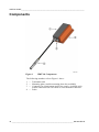
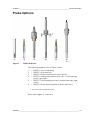
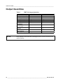
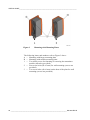
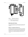
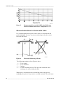
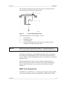
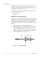
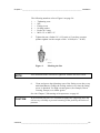
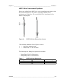
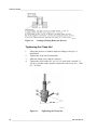
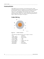
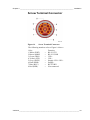

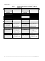
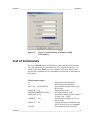
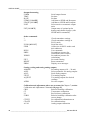

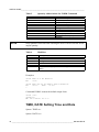
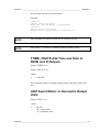
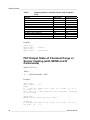
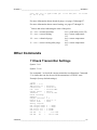


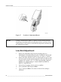
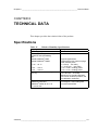

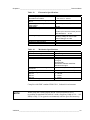
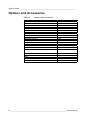
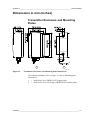
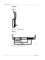
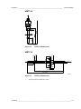
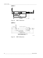
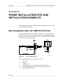
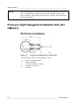
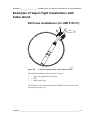
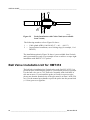
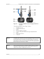


![View a product catalog[PDF/2.6 MB]](http://vs1.manualzilla.com/store/data/005774435_1-dc111fa54cd2566039eb2197a73b68ea-150x150.png)