1
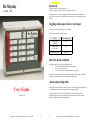
Keyboard
Dr.Mayday
The keys are labeled 1-8 referring to input No. 1-8.
The labels A-D refers to output A-D. (D has been assigned to battery test.)
ALARM - UNIT
To the right of each key 1-8 there are attached keys which are free to mark with information about
what is the use of the inputs. These “hidden” keys, though, has there own function shown by the text
beneath.
Toggling alarm supervision of each input
Press the key (1-8) to toggle alarm supervision of each input.
The red light shows the state of the specific input:
STATE
LIGHT INDICATION
SUPERVISION
SUSPENDED
OFF
SUPERVISION
ACTIVATED
ON
ALARM CONDITION
FLASHING
Reset the alarm condition
If an alarm condition occurs on a input, the red light will flash.
1.
Press the key and the alarm condition will be suspended
2.
Remove the cause of the alarm
3.
Press the key and the alarm supervision will be activated again
With Dr.Bell: If you cannot remove the cause of the alarm you may also press “hidden” key “RESET
to make the siren stop and the key will continue flashing to remind you later.
Alarm acknowledge filter
When an error is detected by an input it must stay for at least 5 seconds to trigger alarm condition. This
is to avoid that electrical noise and non important events are triggering the alarm
User’s Guide
You may rise this value from 5 seconds to a maximum of 255 seconds. This can be used for
monitoring water pressure systems. It is carried out by remote control from a telephone - through
Dr.Bell. See chapter: “Remote control through telephone”
Version No. 1.28
Mayday-128-Users Guide - Klima Design A/S - 11 June 2007
1
2
Mayday-128-Users Guide - Klima Design A/S - 11 June 2007
The “hidden “keys
SYSTEM and 12 VDC - lights
These functions are only available when connected to Dr.Bell speech computer
“HIDDEN” KEY
FUNCTION
Light
ON
SYSTEM
System OK
By alarm situation:
1. Silences the siren
2. Makes an acknowledgement of all alarm entries on
complete system (handled by Dr.Bell)
3.Announces the alarm entries regarding complete system
RESET
HORN
Indicates by lighting LEDs for how many minutes the siren
will sound.
Controlled by dip switch 6 and 7
MUTE
Silence the on-going stream of speech
STATION
PHONE
TEST
12 VDC
Indicates by lighting LEDs the station number series.
1 = Main unit
2= first expanding unit, 3 = second expanding unit and so on.
Controlled by dip switch 1, 2 and 3
Power
supply
(13.8 V)
OK
1. Alarm entry by local input
2. Alarm entry by other unit
3. Faulty communication
4. Faulty telephone line/system
5. Faulty power supply
1. service break
1. Power supply below 12.5 VDC for more then 15 minutes,
or below 11.5 VDC.
2. Power supply below 11.5 VDC during battery test. D-key
is also flashing
Remote control through telephone
Makes Dr.Bell go into setting mode. Only useable by fixed
line system
Please, do also read the user guide for Dr.Bell speech computer, which handles this function.
To test the siren.
Version number is announced in speaker when key is no
longer pressed.
Below: Some examples how to control Dr.Mayday through telephone.
1. Establish connection to Dr.Bell by calling the telephone number.
2. Enter code
3. Use the commands shown below
FUNCTION
Begin service break. Press this key to suspend alarm
supervision for 60 minutes. It will automatically return to
normal supervision when 60 minutes have passed. Or simply
press once more to return to normal supervision again.
SYSTEM light will indicate service break mode by flashing
slowly - once every two seconds.
PAUSE
Every 0.5 seconds:
Every 2.seconds:
Announces the alarm entries regarding complete system even
if they are acknowledged.
SYSTEM light flashes if there are any.
SPEECH
FLASHING
Toggle the alarm supervision ON and OFF
for each input.
Toggle output A, B and C ON and OFF
Battery test
Request announcement of alarm entries
Battery test uses output D to activate an input on the power supply which makes this switch to battery
power mode for 10 minutes. An additional load of power resistors are engaged. The light in the D-key
will be on.
If battery capacity is to low, i.e. voltage drops below 11.5 VDC, the test will stop, and an alarm
situation will be triggered. SYSTEM, 12 VDC and the D-key lights will be flashing. Press hidden key
RESET to acknowledge. New alarm will occur next day. In the meantime please change the battery.
Setting alarm entry acknowledgement time
1-255 seconds (Default 5 seconds)
Set the internal clock
Command sequence
Input 1:
401 * 0 #
...
Input 8: 408 * 0 #
Output A:
Output B:
Output C:
501 * 0 #
502 * 0 #
503 * 0 #
99 * #
601 * 4 * <seconds> #
601 * 29 * <time> #
(8.00, press 800)
Battery test will take place every 24 hours. The time of day may be settled by pressing D-key in 2
seconds at that time. Internal time will be set to 8.00. You may set the internal clock through
telephone, see chapter: “Remote control through telephone”
This function is controlled by dip switch No.5. ON-position means function activated.
Mayday-128-Users Guide - Klima Design A/S - 11 June 2007
3
4
Mayday-128-Users Guide - Klima Design A/S - 11 June 2007