1
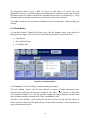
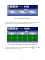
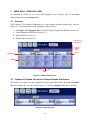
APX™ Personnel Accountability Application
User Manual
8 May 2015
Systems Definition, Inc.
5904 Richmond Highway
Suite 330
Alexandria, VA 22303
703-717-0222
www.systemsdefinition.com
www.firegroundaccountability.com
Copyright © 2015 Systems Definition, Inc., All Rights Reserved.
TABLE OF CONTENTS
INTRODUCTION.............................................................................................................. 1-1
1
1.1
1.2
1.3
2
APX PERSONNEL ACCOUNTABILITY APPLICATION OVERVIEW ................................................................... 1-1
DOCUMENT ORGANIZATION......................................................................................................................... 1-2
DOCUMENT CONVENTIONS .......................................................................................................................... 1-2
MAYDAYS ......................................................................................................................... 2-1
2.1
2.2
3
MANUAL MAYDAY ...................................................................................................................................... 2-1
VERBAL MAYDAY ........................................................................................................................................ 2-1
LAUNCHING APAA......................................................................................................... 3-1
3.1
4
STARTING APAA ON A PORTABLE COMPUTER ............................................................................................ 3-1
APAA OVERVIEW ........................................................................................................... 4-1
4.1 FUNCTION BUTTONS .................................................................................................................................... 4-1
4.1.1 Channels Button ........................................................................................................................................ 4-2
4.1.2 View Button .............................................................................................................................................. 4-2
4.1.3 Relieved Button ......................................................................................................................................... 4-4
4.1.4 Clear Button .............................................................................................................................................. 4-5
4.2 RF MODEM STATUS BOX ............................................................................................................................. 4-6
4.3 INCIDENT TIMER .......................................................................................................................................... 4-6
4.4 MEGAPHONE BUTTON .................................................................................................................................. 4-6
4.4.1 Evacuation ................................................................................................................................................. 4-7
4.4.2 PAR/Rollcall ........................................................................................................................................... 4-10
4.5 LAST TX ..................................................................................................................................................... 4-12
5
USING APAA - GRAPHICAL VIEW ............................................................................. 5-1
5.1 OVERVIEW ................................................................................................................................................... 5-1
5.2 COLLAPSE ALL/ EXPAND ALL UNITS AND COLLAPSE/EXPAND UNIT BUTTONS ........................................... 5-1
5.3 UNIT ASSIGNMENTS PULL-DOWN ................................................................................................................ 5-2
5.4 ROSTER BUTTONS ........................................................................................................................................ 5-3
5.5 MEMBER DIALOG BOXES ............................................................................................................................. 5-3
5.5.1 Mayday/Resolve Button ............................................................................................................................ 5-5
5.5.2 Account/Unaccount Button ....................................................................................................................... 5-6
5.5.3 Poll Radio Button ...................................................................................................................................... 5-8
6
USING APAA – TABLE VIEW ....................................................................................... 6-1
6.1 RADIO STATUS TABLE ................................................................................................................................. 6-1
6.1.1 Mayday Transmission Highlighting in Radio Status Table ....................................................................... 6-3
6.1.2 Assign and Resolve Mayday from Radio Status Table ............................................................................. 6-3
6.1.3 Radio Polling ............................................................................................................................................. 6-5
6.2 ALERTS TABLE............................................................................................................................................. 6-6
6.3 COMPANIES TABLE ...................................................................................................................................... 6-8
6.3.1 Company Roster ........................................................................................................................................ 6-8
7
LOG FILES ........................................................................................................................ 7-1
7.1
7.2
LOG VIEWER ................................................................................................................................................ 7-1
LOG FILES .................................................................................................................................................... 7-2
ii
LIST OF FIGURES
Figure 1-1. APX Personnel Accountability Application User Interface .................................................................... 1-2
Figure 3-1. ERROR: RFModem Not Detected .......................................................................................................... 3-1
Figure 4-1. APAA Main Screen (Graphical View) ................................................................................................... 4-1
Figure 4-2. Upper Main Screen ................................................................................................................................. 4-1
Figure 4-3. Select Your Channel ............................................................................................................................... 4-2
Figure 4-4. Graphical View - Received Mayday Message ........................................................................................ 4-3
Figure 4-5. Table View - Received Mayday Message ............................................................................................... 4-3
Figure 4-6. Relieve Companies Dialog Box .............................................................................................................. 4-4
Figure 4-7. Relieve Companies Dialog Box Showing a Company That Has Been Relieved .................................... 4-4
Figure 4-8. Clear Data Options .................................................................................................................................. 4-5
Figure 4-9. Incident Timer Reset and All Data Cleared (Graphical View) ............................................................... 4-6
Figure 4-10. Reset Incident Timer ............................................................................................................................. 4-6
Figure 4-11. Evacuation/PAR/Rollcall Buttons ......................................................................................................... 4-7
Figure 4-12. Begin Evacuation .................................................................................................................................. 4-7
Figure 4-13. Viewing Ongoing Evacuation Status .................................................................................................... 4-8
Figure 4-14. Manually View Status of Individual Member ....................................................................................... 4-9
Figure 4-15. End Evacuation ..................................................................................................................................... 4-9
Figure 4-16. Begin Rollcall ..................................................................................................................................... 4-10
Figure 4-17. Active Rollcall (Collapsed View) ....................................................................................................... 4-11
Figure 4-18. Expanded View PAR/Rollcall Showing 12 of 12 Members Accounted For....................................... 4-11
Figure 4-19. End Rollcall Button............................................................................................................................. 4-12
Figure 5-1. APAA Graphical View ........................................................................................................................... 5-1
Figure 5-2. Collapsed Units ....................................................................................................................................... 5-1
Figure 5-3. Individual Unit Collapsed/Expanded ...................................................................................................... 5-2
Figure 5-4. Assignment Pull-Down ........................................................................................................................... 5-2
Figure 5-5. Roster ...................................................................................................................................................... 5-3
Figure 5-6. Member Dialog box During Evacuation or PAR/Rollcall ...................................................................... 5-4
Figure 5-7. Member Dialog box When Not in Evacuation or PAR/Rollcall ............................................................. 5-4
Figure 5-8. Assign Mayday ....................................................................................................................................... 5-5
Figure 5-9. Mayday ................................................................................................................................................... 5-5
Figure 5-10. Resolve Mayday.................................................................................................................................... 5-6
Figure 5-11. Account for Member ............................................................................................................................. 5-6
Figure 5-12. Accounted For Member in Green ......................................................................................................... 5-7
Figure 5-13. Account Button is Unavailable until Mayday is Resolved.................................................................... 5-7
Figure 5-14. Manually Unaccount Button ................................................................................................................. 5-8
Figure 5-15. Unaccounted For Member in Yellow .................................................................................................... 5-8
Figure 5-16. Poll Radio ............................................................................................................................................. 5-9
Figure 5-17. Polling In Progress ................................................................................................................................ 5-9
Figure 5-18. Radio Unpollable ................................................................................................................................ 5-10
Figure 6-1. APAA Main Screen ................................................................................................................................ 6-1
Figure 6-2. Radio Status Table .................................................................................................................................. 6-2
Figure 6-3. Mayday ................................................................................................................................................... 6-2
Figure 6-4. Unpollable ............................................................................................................................................... 6-2
Figure 6-5. Channel Left ........................................................................................................................................... 6-3
Figure 6-6. Radio Off ................................................................................................................................................ 6-3
Figure 6-7. Mayday Transmission Highlighting in Radio Status Table .................................................................... 6-3
Figure 6-8. Assign Mayday from Radio Status Table ............................................................................................... 6-4
Figure 6-9. Resolve Mayday...................................................................................................................................... 6-4
Figure 6-10. Resolved Mayday in Alerts Table ......................................................................................................... 6-5
Figure 6-11. Polling from Radio Status Table ........................................................................................................... 6-5
Figure 6-12. Poll Radio Failure ................................................................................................................................. 6-6
Figure 6-13. Alerts Table Showing an Active Mayday and a Resolved Mayday ...................................................... 6-7
Figure 6-14. Accessing Radio Data Box from Alerts Table ...................................................................................... 6-7
Figure 6-15. Companies Table .................................................................................................................................. 6-8
iii
Figure 6-16. Companies Table Detail ........................................................................................................................ 6-8
Figure 6-17. Company Roster.................................................................................................................................... 6-9
Figure 6-18. Refresh Roster ....................................................................................................................................... 6-9
Figure 7-1. Log Viewer ............................................................................................................................................. 7-1
Figure 7-2. Current and Previous Log Files .............................................................................................................. 7-2
Figure 7-3. Log Files ................................................................................................................................................. 7-3
iv
ACRONYMS AND ABBREVIATIONS
Acronym
Definition
APAA
APX Personnel Accountability Application
APX
Designator For Motorola First Responder Radios
ID
Identification
MSI
Motorola Solutions, Inc.
NAC
Network Access Code
PAR
Personnel Accountability Request
PC
Personal Computer
PTT
Push-To-Talk
RF
Radio Frequency
SDI
Systems Definition, Inc.
TX
Transmit/Transmission
NOTES
Motorola and APX are trademarks or registered trademarks of Motorola Trademark Holdings, LLC.
EasyStaff® is a registered trademark of Systems Definition, Inc.
RECORD OF CHANGES
RELEASE
DATE
1
2
3
4
5
6
1 June 2013
15 June 2013
29 August 2013
9 October 2013
4 February 2014
8 May 2015
TITLE OR BRIEF DESCRIPTION
Initial Release
Revision Release
Revision Release
Revision Release
Revision Release
Revision Release
v
ENTERED BY
B. Seale
B. Seale
B. Seale
B. Seale
B. Seale
V. Barry
1
INTRODUCTION
This document provides user instruction and guidance to operate the APX Personnel
Accountability Application (APAA).
1.1
APX Personnel Accountability Application Overview
APAA assists incident commanders with personnel accountability and emergency alerting
capabilities through the use of Motorola Solutions, Inc. (MSI) APX portable subscriber radios in
conjunction with aggregated department radio identification and personnel data.
APAA provides accountability and emergency alerting capabilities when used with properly
configured APX radios. Figure 1-1 shows the APAA user interface. Table 1-1 summarizes
supported features. APAA runs on in-vehicle mobile terminals (e.g., Toughbook Personal
Computer) or in transportable units for conditions requiring “remote” application capability.
Major functions include:
•
Capturing, displaying, and storing emergency alert transmissions received from portable
APX radios
•
Immediately identifying subscriber radio Push-To-Talk (PTT) transmissions, including
emergency alert transmissions, by timestamp, member name, unit, and position
assignment using data from department data sources (if available)
•
Conducting rapid electronic Personnel Accountability Requests (PARs), rollcalls, and
evacuations via PTT
•
Conducting acknowledged evacuations
•
Recording detailed incident log files denoting PTT data and accountability events (e.g.,
rollcalls, alerts, etc.) to assist post-incident record-keeping and incident reviews
Table 1-1. APX Accountability Application Feature Set
Feature
Summary Description
PTT ID Display
Displays radio ID number or radio alias
Emergency Alert Indicator
Displays emergency alert message data
EVAC Alerting
Sends/receives evacuation message/evacuation acknowledgements
Accountability Registration
Detects/registers subscriber radio at power-up
Polling
Polls for subscriber radios in the vicinity
Power Down Indicator
Identifies subscriber radios that have powered off
Channel-Left Indicator
Identifies subscriber radios that have changed channels
Battery Level Indicator
Identifies subscriber radios with low battery levels
1-1
Figure 1-1. APX Personnel Accountability Application User Interface
1.2
Document Organization
This document is organized as follows:
•
•
•
•
•
•
•
1.3
Section 1 – Introduction
Section 2 – Maydays
Section 3 – Launching APAA
Section 4 – APAA Overview
Section 5 – Using APAA – Graphical View
Section 6 – Using APPA – Table View
Section 7 – Log Files
Document Conventions
Throughout this document, text in Courier Bold reflects actual text on the APAA screen,
usually on a button or title bar.
Red text and arrows are used for labeling purposes and do not appear on the actual APAA
screen.
Text for Emergency Alert buttons, Companies table, and Company are configurable through the
APAA Configuration Utility. The terms Emergency Alert, Mayday, Companies, and Company
are used in this document.
Users can use either the touch-screen or the touch-pad mouse on the keyboard to interact with the
APAA. The terms “select” and “click” are used throughout this document to indicate touching
the touch-screen or clicking with the touch-pad mouse.
1-2
2
MAYDAYS
For the purposes of APAA, there are two types of Maydays:
• Manual Mayday (section 2.1)
• Verbal Mayday (section 2.2)
To notify of a Mayday message being received, APAA emits an audible alarm and the title bars,
buttons, and other APAA screen elements flash red. The member’s box in the Unit Radio Data
area and the row in the Radio Status table row are highlighted in red (section 5.5.1 and
6.1.1). The Mayday also appears highlighted red in the Alerts table (section 6.2). If available
and configured, the Mayday information may be sent to a printer to create a hard-copy record.
2.1
Manual Mayday
A manual Mayday occurs when a member pushes the radio Mayday (Emergency Alert) button
on the subscriber radio causing the radio to transmit a Mayday message.
Manual Maydays can be resolved either by the member pushing the Mayday button again to
clear the alert, or by the APAA user (section 5.5.1). Note that resolving the Mayday on APAA
does not act on the subscriber radio; the member is still required to push and hold the Mayday
button on the radio to clear the message.
If radio communications is hindered, it may be necessary for the APAA user to resolve the
Mayday displayed on-screen even if the member has already pushed the Mayday button a second
time (thereby clearing the message at the subscriber radio).
2.2
Verbal Mayday
A verbal Mayday is initiated by the APAA user (section 5.5.1) when a member gives a Mayday
(member in distress) verbally over the handie-talkie radio, but does not push the Mayday button.
Verbal Emergency Alerts can be resolved by the APAA user (section 5.5.1).
2-1
3
LAUNCHING APAA
This section provides information on how to start APAA on a portable Personal Computer (PC).
APAA installation and configuration information is contained within separate documentation
(APAA Installation and Configuration Guide).
3.1
Starting APAA on a Portable Computer
To start APAA on a portable unit:
1. Open the PC.
2. Power on the PC.
3. Launch APAA by selecting APAA from the list of available programs on the Windows
Start menu. A shortcut to the application may be created on the PC desktop to reduce
required navigation steps.
When a connection to the Radio Frequency (RF) Modem is established, the channel name is
displayed in the tab below the main buttons and the Modem status box is highlighted in green
(section 4.1.1). Depending on the APAA configuration settings, there may also be an audible
alert notifying the user that the RF Modem has connected to a radio channel.
APAA supports the use of one channel at a time and permits selection of any available,
configured Department channel.
If the ERROR: RFModem Not Detected dialog box is displayed upon launching APAA, as
shown in Figure 3-1, use the APAA Configuration utility to assign the correct RF Modem
module.
Figure 3-1. ERROR: RFModem Not Detected
3-1
4
APAA OVERVIEW
This section provides an overview of APAA. Figure 4-1 shows the main APAA components.
Figure 4-1. APAA Main Screen (Graphical View)
The upper portion of the main APAA screen (see Figure 4-2) contains the function buttons, the
RF modem status box, the incident timer, the megaphone button, and a notification of the radio
that transmitted last (Last Tx :).
FUNCTION
BUTTONS
MEGAPHONE
BUTTON
RF MODEM
STATUS
INCIDENT
TIMER
RADIO THAT LAST
TRANSMITTED
Figure 4-2. Upper Main Screen
4.1
Function Buttons
The following function buttons are described in more detail in the referenced sections:
•
Channels (section 4.1.1)
•
View (section 4.1.2)
4-1
•
Relieved (section 4.1.3)
•
Clear (section 4.1.4)
4.1.1 Channels Button
APAA supports the use of one channel at a time and permits selection of any available,
configured Department channel.
To designate the radio channel being monitored by APAA, click the Channels button to
launch the Select Your Channel dialog box (Figure 4-3).
Figure 4-3. Select Your Channel
In the Select Your Channel dialog box, click the button for the desired channel, then
click Select to connect to the new channel. Click Cancel to close the dialog box without
making any changes.
Please note that during the brief channel reconnect period, APAA will not monitor radio
transmissions.
4.1.2 View Button
Clicking the View button displays the icons for the two views available in APPA — the
Graphical view (section 5) and the Table view (section 6). These two views display
accountability activities and status in different ways. Figure 4-4 and Figure 4-5 illustrate the two
different views during a received Mayday.
The Graphical view provides a top-level, visual look at accountability status, generally organized
by department unit. It enables setting of unit timers and unit assignments, among other features.
4-2
Figure 4-4. Graphical View - Received Mayday Message
The Table view provides a column- and row-based display of personnel and status. The Table
view also displays an Alerts table, which identifies active or resolved Maydays.
Figure 4-5. Table View - Received Mayday Message
APAA users may prefer one view over the other, as each view provides different visualization of
accountability activities, status, and data along with different features and functions.
4-3
4.1.3 Relieved Button
The Relieved button allows users to view Department Companies and to filter on desired
Companies. Click the Relieved button to display the Relieve Companies dialog box (see
Figure 4-6).
NUMBER OF
COMPANIES
ACTIVE/SELECTED
Figure 4-6. Relieve Companies Dialog Box
The left column in the Relieve Companies dialog box lists applicable Departments. The
Department highlighted in green is the active Department with its associated Companies listed to
the right. The numbers in parentheses following the Department name denote the number of
Companies active/selected as compared to the overall number of Companies in the Department
(see Figure 4-6).
Companies with radios detected on-scene are shown in green. Grey indicates no radios from that
Company have been detected on scene. As shown in Figure 4-7, the Incident Commander can
select an individual Company to filter out PTT traffic from (note the red strike-out symbol in
Engine 3). The PTT data is still collected in the log files, but is not shown in APAA.
PTT TRAFFIC FROM
THIS COMPANY HAS
BEEN FILTERED OUT
Figure 4-7. Relieve Companies Dialog Box Showing a Company That Has Been Relieved
4-4
The Department shown in grey (“BFD”) in Figure 4-6 and Figure 4-7 on the left is not
highlighted and may be selected to display that Department’s Companies on the right. Multiple
Departments may be available within APAA depending on how APAA is configured (e.g., set-up
to identify other local Departments that may participate at mutual aid incidents).
Click OK to complete your selections or Cancel to close the dialog box without making any
changes.
4.1.4 Clear Button
To clear data from the Graphical and Table views, click the Clear button. In the dialog box
that appears (see Figure 4-8), select/unselect the following (default is all items checked):
•
Clear Rosters
•
Reset Incident Timer
•
Clear Radio Data
Figure 4-8. Clear Data Options
Click Cancel to close the dialog box without making any changes.
Click the Clear button with all items checked to remove all radio transmission data,
unit/roster data, and timer data from the Graphical and Table views. Figure 4-9 shows data
cleared from the Graphical view. Please note that clearing data removes Mayday and other alert
data, including alert data contained in the Table view Alerts table.
Note that, even if all data is cleared using this function of APAA, the log files that capture all
radio transmission data will still capture and save all data. Refer to section 7 of this document for
more information on log files.
4-5
Figure 4-9. Incident Timer Reset and All Data Cleared (Graphical View)
4.2
RF Modem Status Box
The RF modem status box is highlighted in green when APAA is connected to the RF modem.
The box is highlighted in red when there is no connection to the RF modem. The box may be
highlighted in yellow during a brief initialization phase.
4.3
Incident Timer
The incident timer starts when APAA loads and begins operations (e.g., at vehicle power-up).
Click on the incident timer then click on OK in the Reset Incident Timer dialog box to reset it to
00:00:00 (see Figure 4-10). Click Cancel to close the dialog box without making any changes.
Figure 4-10. Reset Incident Timer
4.4
Megaphone Button
Evacuation and PAR/Rollcall functions are accessed by clicking the megaphone icon
reveal a pull-down with the Evac and PAR/Rollcall buttons (see Figure 4-11).
4-6
to
MEGAPHONE
BUTTON
EVAC
BUTTON
PAR/ROLLCALL
BUTTON
Figure 4-11. Evacuation/PAR/Rollcall Buttons
4.4.1 Evacuation
One of the most important functions of APAA is to provide the capability to evacuate members
at an incident by allowing the Incident Commander to initiate an evacuation command from
APAA. The evacuation command is sent from APAA via the mobile radio connected to the
APAA PC to all portable radios at the incident. The portable radios receive the evacuation
command and begin to emit a loud tone. Members then press their radio’s PTT button to
acknowledge receipt of the evacuation command. In the Graphical view, APAA tracks the
received acknowledgements and identifies members that have acknowledged the evacuation
command as well as members who have not acknowledged the command.
Select the megaphone icon and then click the Evac button to launch the Initiate
Evacuation dialog box. See Figure 4-12. Click the Begin Evacuation button to start
evacuation.
Figure 4-12. Begin Evacuation
4-7
During Evacuation activities, APAA automatically switches to the Graphical view and displays
the number of members accounted for, along with the total number of members to account for, in
the upper/status area next to the Megaphone button.
Each member’s acknowledgement status is shown via the color-coded status box (see Figure
4-13). Green indicates acknowledgement received, yellow indicates no acknowledgement
received, and red indicates Mayday received. For convenience (e.g., in the case of a large
incident with many responding units), evacuation may be conducted in the collapsed view
(member details hidden) or expanded view (member details shown).
Figure 4-13. Viewing Ongoing Evacuation Status
During Evacuation, the Incident Commander may perform additional accountability actions for
an individual member by selecting their name to display relevant member details (see Figure
4-14). These actions include manually assigning Mayday (emergency alert) status. For example,
during evacuation, if a member indicates verbally that he or she is in immediate peril, the
Incident Commander could click the Mayday button for that member. Selecting Mayday will
cause that member’s details box to be highlighted in red, allowing the Incident Commander to
easily maintain identity of that member and to focus assistance for that member.
The Incident Commander can also manually account for a member, or poll a member’s radio, to
determine whether the radio is still within the vicinity and powered on.
To terminate evacuation activities, click the End evacuate button
Evacuation in the dialog box. See Figure 4-15.
then click End
Click Cancel to close the dialog box without ending the Evacuation.
Please note that automatic radio polling, if selected as part of APAA configuration settings, is
halted during evacuation activities.
A log file is created for each evacuation conducted. Refer to section 7 of this document for
additional information on log files.
4-8
Figure 4-14. Manually View Status of Individual Member
Figure 4-15. End Evacuation
4-9
4.4.2 PAR/Rollcall
Another important function of APAA is to provide the capability to conduct a PTT-based PAR
check or Rollcall to rapidly account for members by capturing member PTT acknowledgements.
This significantly reduces the time required to conduct a PAR/Rollcall and reduces the load on
the radio system by minimizing voice coordination typically required to complete a
PAR/Rollcall. It is similar in some respects to conducting evacuation activities. However, unlike
the EVAC command message, there is no PAR/Rollcall command sent out by APAA over the
mobile radio. The Incident Commander must initiate the PAR check or Rollcall via voice.
The PAR button (previously shown in Figure 4-11) allows APAA users to initiate a PAR check
or Rollcall during which members acknowledge by keying their portable radios. Clicking the
PAR/Rollcall button launches the Rollcall dialog box, as shown in Figure 4-16.
Figure 4-16. Begin Rollcall
APAA PAR/Rollcall activities are performed as summarized below:
1. The Incident Commander clicks the Begin Rollcall button (see Figure 4-16) to display the
APAA PAR/Rollcall dialog box.
2. The Incident Commander requests a PAR check or Rollcall via voice over the radio system to
on-scene members. Typically, the Incident Commander states the purpose (e.g., conducting a
PAR check of some or all units to determine a member head count and member status). It is
useful for the Incident Commander to remind members to respond by selecting the radio PTT
key.
3. Members then click the radio PTT button to acknowledge their presence back to the Incident
Commander (see Figure 4-17). In the Graphical view, APAA tracks the received PTT
acknowledgements, identifying members who have acknowledged and members who have
not acknowledged. The Rollcall dialog box displays units, radios, and personnel at the
incident. Accounted-for radios are displayed in green, unaccounted-for radios are displayed
in yellow, and radios that have sent a Mayday are displayed in red.
4-10
Figure 4-17. Active Rollcall (Collapsed View)
The default PAR/Rollcall view shows the units in collapsed view. The units can be expanded to
see additional member data by clicking the Expand All button. See Figure 4-18.
Figure 4-18. Expanded View PAR/Rollcall Showing 12 of 12 Members Accounted For
To terminate PAR/Rollcall activities, click the End Rollcall button
Rollcall in the dialog box (see Figure 4-19).
4-11
and select End
Figure 4-19. End Rollcall Button
Click Cancel to close the dialog box without ending the PAR/Rollcall.
Please note that an evacuation cannot be conducted during an active PAR/Rollcall. After a
PAR/Rollcall is started, the Evacuate button cannot be clicked until the Rollcall dialog
box is closed.
Please note also that automatic radio polling is halted during PAR/Rollcall.
4.5
Last Tx
The Last Tx status line to the right of the Megaphone button displays the name of the radio
that was last keyed and detected by the RF modem.
4-12
5
USING APAA - GRAPHICAL VIEW
As explained in section 4.1.2, to access the Graphical View in APAA, click on the View
function button then click Graphical.
5.1
Overview
The Graphical View displays information in a visual manner generally organized by unit (see
Figure 5-1). The main functions and capabilities of this view are:
•
Collapse All/Expand All Units and Collapse/Expand Unit Buttons (section 5.2)
•
•
•
Unit Assignments Pull-Downs (section 5.3)
Roster Buttons (section 5.4)
Member Boxes (section 5.5)
COLLAPSE ALL/
EXPAND ALL
COLLAPSE/
EXPAND
UNIT
ROSTER
ASSIGNMENTS
MEMBER
UNITS
Figure 5-1. APAA Graphical View
5.2
Collapse All/ Expand All Units and Collapse/Expand Unit Buttons
The default view shows all units expanded to include applicable details. Selecting Collapse
All will collapse the view for all units (Figure 5-2). Selecting Expand All shows all units.
Figure 5-2. Collapsed Units
5-1
Each unit can also be expanded or collapsed individually by clicking the Collapse/Expand button
(see Figure 5-3). Note that the accountability status colors (green, yellow, red) are
maintained whether the unit is displayed in a collapsed or expanded view.
Figure 5-3. Individual Unit Collapsed/Expanded
5.3
Unit Assignments Pull-Down
APAA allows the Incident Commander to assign units to specific assignments. Assignments are
defined within the APAA Configuration Utility. The Assignments pull-down list is used to
designate a unit with a role/location at an incident (see Figure 5-4).
Figure 5-4. Assignment Pull-Down
5-2
Units with designated assignments will be displayed left-most in priority-order, matching the
order of the assignments within the pull-down list. Units with the default "Unassigned"
classification will be shown to the right.
5.4
Roster Buttons
The Roster icon
displays ride list data, if available, within the accountability system. For
example, SDI’s EasyStaff® application is bundled with APAA to provide departments with the
capability to create on-line ride lists/tour rosters that can be downloaded to APAA. In this way,
the Incident Commander sees the names of members on the fireground.
The Roster can be refreshed to display the most current data by selecting the Refresh
Roster button (see Figure 5-5).
Figure 5-5. Roster
5.5
Member Dialog Boxes
Selecting a member from the Unit Radio Data box launches the Member dialog box. The
Member dialog box, as shown in Figure 5-6 and Figure 5-7 includes the following buttons:
•
•
Mayday/Resolve: Click this button to assign a Mayday to the selected member or
resolves a Mayday (section 5.5.1).
Account/Unaccount: Only available/viewable when system is in PAR/Rollcall or
Evacuation mode (Figure 5-6). Click this button to account/unaccount for the selected
member (section 5.5.2). The Account button is only displayed when the selected
member is unaccounted for, and vice-versa. Note that when not in a PAR/Rollcall or
Evacuation mode, the Account/Unaccount button is unavailable.
Poll Radio: Click this button to manually poll for a radio (section 5.5.3).
•
Cancel: Click this button to close the Member dialog box without making changes.
•
5-3
Figure 5-6. Member Dialog box During Evacuation or PAR/Rollcall
Figure 5-7. Member Dialog box When Not in Evacuation or PAR/Rollcall
5-4
5.5.1 Mayday/Resolve Button
To manually assign a Mayday, click the Member box. The Member dialog box is displayed. If
the selection is incorrect, click the Cancel button to close the dialog box without assigning a
Mayday. If the selection is correct, click the Mayday button (see Figure 5-8).
Figure 5-8. Assign Mayday
The member turns red to indicate a Mayday. The application’s background flashes red as well
(Figure 5-9). An accounted-for member assigned a Mayday will no longer be considered
accounted for.
Figure 5-9. Mayday
5-5
To resolve the Mayday, click on the Member again and click the Resolve button in the
Member dialog box (see Figure 5-10).
Figure 5-10. Resolve Mayday
5.5.2 Account/Unaccount Button
To manually account for a member during an electronic PAR/Rollcall, click the Account
button from the Member dialog box (see Figure 5-11).
Figure 5-11. Account for Member
5-6
The member’s name is now highlighted in green, as shown in Figure 5-12.
Figure 5-12. Accounted For Member in Green
An active Mayday must be resolved before that member can be manually accounted for (see
section 5.5.1 for information on resolving Maydays).
Figure 5-13. Account Button is Unavailable until Mayday is Resolved
To manually designate a member as unaccounted for, click the Unaccount button in the
Member dialog box (see Figure 5-14).
5-7
Figure 5-14. Manually Unaccount Button
The member’s name is now highlighted in yellow, as shown in Figure 5-15.
Figure 5-15. Unaccounted For Member in Yellow
5.5.3 Poll Radio Button
To manually poll a radio, click the Poll Radio button in the Member dialog box (Figure
5-16).
5-8
Figure 5-16. Poll Radio
The Poll Status displays Polling… and the Poll Radio button is grayed-out while the
RF Modem polls for the selected radio, as shown in Figure 5-17. The Poll Status changes
to Success! if the selected radio is detected.
Figure 5-17. Polling In Progress
5-9
The Poll Status changes to Failed and the Radio Unpollable Icon displays if the radio is
not detected, as shown in Figure 5-18.
RADIO
UNPOLLABLE
ICON IS
DISPLAYED
WHEN RADIO
POLL FAILS
Figure 5-18. Radio Unpollable
To enable the manual polling and the Poll Radio button, see the APAA Installation and
Configuration Guide.
5-10
6
USING APAA – TABLE VIEW
This section provides instructions to use APAA in Table View. Figure 6-1 highlights the
following components of the APAA Table View screen:
•
Radio Status Table (section 6.1)
•
Alerts Table (section 6.2)
•
Companies Table (section 6.3)
COMPANIES
TABLE
RADIO
STATUS
TABLE
ALERTS
TABLE
Figure 6-1. APAA Main Screen
6.1
Radio Status Table
Click the View function button at the top of the screen to view the Radio Status table. This
view allows users to see a log of transmissions as they occur. Each row represents a PTT
transmission, as shown in Figure 6-2.
6-1
Figure 6-2. Radio Status Table
The most recent transmission displays at the top of the table by default. The sort order of the
Radio Status table can be modified using the APAA Configuration tool. See APAA Installation
and Configuration Guide.
The Radio Status table columns display the following:
•
Radio Assignment: Member’s unit and position
•
Name: Member’s name
•
Transmit Time: Time of most recent transmission
•
Battery: Percentage of radio battery available
•
Status: Identifies any known alerts for a member using the following icons:
o Mayday: Yellow triangle with exclamation point; notifies the user that the
associated radio has an active Emergency Alert, as shown in Figure 6-3.
Figure 6-3. Mayday
o Unpollable: Radio with question mark; notifies the user that the associated radio
was not reached through polling within the predetermined time interval (see the
APAA Installation and Configuration Guide), as shown in Figure 6-4.
Figure 6-4. Unpollable
6-2
o Channel Left: CHAN LEFT text; notifies the user that the associated radio has
left the channel currently selected by the RF modem, as shown in Figure 6-5.
Figure 6-5. Channel Left
o Radio Off: RADIO OFF text; notifies the user that the associated radio is off, as
shown in Figure 6-6.
Figure 6-6. Radio Off
Please note that radios in orange are minor alerts (e.g., low battery, radio off, etc.), radios in red
are major alerts (e.g., Mayday), and radios in yellow are resolved major alerts (e.g., resolved
Emergency Alerts).
6.1.1 Mayday Transmission Highlighting in Radio Status Table
The Radio Status table displays active Emergency Alerts highlighted red, as shown in
Figure 6-7. Emergency Alerts remain highlighted red until they are resolved.
Figure 6-7. Mayday Transmission Highlighting in Radio Status Table
6.1.2 Assign and Resolve Mayday from Radio Status Table
To assign a Mayday, select the member’s row from the Radio Status table then click the
Mayday button in the resulting dialog box. Click Cancel button to close the dialog box
without assigning an Emergency Alert (see Figure 6-8).
6-3
Figure 6-8. Assign Mayday from Radio Status Table
To resolve a Mayday, click the Resolve button (see Figure 6-9).
Figure 6-9. Resolve Mayday
6-4
The resolved alert is highlighted in yellow in the Alerts table (see Figure 6-10).
Figure 6-10. Resolved Mayday in Alerts Table
6.1.3 Radio Polling
To manually poll a radio, select the radio in the Radio Status table then click the Poll Radio
button. The Poll Status displays Polling… and the Poll Radio button is grayed-out
while the RF Modem polls for the selected radio, as shown in Figure 6-11.
Figure 6-11. Polling from Radio Status Table
The Poll Status changes to Success! if the selected radio is detected. The Poll
Status changes to Failed and the Radio Unpollable icon is displayed if the radio is
not detected, as shown in Figure 6-12.
6-5
Figure 6-12. Poll Radio Failure
To enable manual polling and the Poll Radio button, see the APAA Installation and
Configuration Guide.
6.2
Alerts Table
The Alerts table displays active and resolved Maydays. Each table row represents a Mayday
transmission, with the most recent Maydays displayed at the top of the table.
The Alerts table columns display the following Emergency Alert information:
•
Radio Assignment: Member’s unit and position
•
Name: Name of member who sent the Emergency Alert transmission
•
Given: Time of Emergency Alert transmission
•
Resolved: Time of Mayday resolution
• Type: VERBAL or MANUAL (refer back to section 2 of this document)
Rows for active Maydays are highlighted red. The procedure to manually resolve a Mayday
from the Alerts table is the same as for manually resolving a Mayday from the Radio Status
table. Click the Resolve button. When a Mayday is resolved, the row for that alert highlights
yellow (see Figure 6-13).
6-6
Figure 6-13. Alerts Table Showing an Active Mayday and a Resolved Mayday
Accounting/unaccounting for radios and Polling Radios from the Alerts table uses the same
procedures as for the Radio Status table (section 5.5.2 and section 5.5.3). Select
Account/Unaccount to either account or unaccount for a radio or select Poll Radio to poll the
radio (Figure 6-14).
CLICK A RADIO
ASSIGNMENT IN
ALERT TABLE
TO OPEN
RADIO DATA BOX
Figure 6-14. Accessing Radio Data Box from Alerts Table
6-7
6.3
Companies Table
The Companies table displays companies with radio activity, as shown in Figure 6-15. Radio
transmissions from companies in the Companies table are displayed in the Radio Status table.
COMPANIES TABLE
RADIO TRANSMISSION
DATA FROM COMPANIES
LISTED IN COMPANIES
TABLE
Figure 6-15. Companies Table
The Companies table (Figure 6-16) columns display the following:
•
Company Name: Company identification
•
Added: Time the company was added to the table (e.g., time that first transmission was
received from a member of that company, or dispatched time, if available)
Figure 6-16. Companies Table Detail
6.3.1 Company Roster
To view a company’s roster information, select its table row from the Companies table. A
dialog box labeled with the Company name appears, as shown in Figure 6-17.
The Company Roster displays a table with one row for each member of the company. Columns
list the following member information:
•
Assignment: Member’s unit and position
•
Radio: Radio ID
•
Full Name: Member’s name
6-8
Figure 6-17. Company Roster
To download the most recent ride list information for a company, click the Refresh Roster
button. The button becomes grayed out and reads Attempting Roster Update…, as
shown in Figure 6-18, while APAA attempts to update the company’s ride list.
Figure 6-18. Refresh Roster
Upon downloading the most recent ride list information, the Refresh Roster button
returns to the default setting and the new ride list information is displayed. If the APAA is unable
to update the company’s ride list, the button does not return to the default setting, and a dialog
box notifies the user of the failed attempt.
6-9
7
LOG FILES
APAA generates and records log files each time the application is used. Users can view log files
either from the APAA application or from the logs folder contained within the PC’s APAA
folder. Four types of log files are generated:
•
•
7.1
Incident: Captures information pertaining to incident data (e.g., application start,
portable radio transmissions, etc.)
Diagnostic: Captures information pertaining to APAA status (e.g., software module
upload, roster/radio list download status, error messages, etc.)
•
PAR/Rollcall: Captures information pertaining to PAR/Rollcall data (e.g., PAR/Rollcall
start/end, accounted for personnel, etc.); this file is only created only if a PAR/Rollcall
was conducted during the application session.
•
Evacuation: Captures information pertaining to evacuation data (e.g., when a Mayday
was received, who had a Mayday, who was unaccounted for, etc.)
Log Viewer
With the APAA application open, press CTRL+SHIFT+L to open the Log Viewer dialog box,
as shown in Figure 7-1. This dialog box allows the user to view log files for the APAA.
Figure 7-1. Log Viewer
Check the Current Files Only box to display log files for the current APAA session.
Uncheck this box, then click the drop-down list to display log files for current and previous
logged APAA sessions, as shown in Figure 7-2. Log file dates and times are appended to the
beginning of the log file name.
7-1
Figure 7-2. Current and Previous Log Files
Click the Refresh Current button to view log data created since the initial log selection or
last refresh.
Click the X in the top right corner of the window to close the Log Viewer.
7.2
Log Files
APAA log files are stored in the logs folder located within the APAA folder on the PC. Log
files are labeled by date, time, and type (e.g., incident, diagnostic, evac, or rollcall), as shown in
Figure 7-3.
To view the logs, open the logs folder and right-click the desired log file. Select Open With
and select WordPad.
7-2
Figure 7-3. Log Files
7-3