1
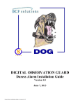
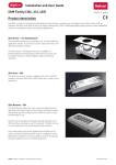
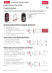
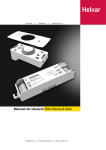
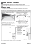
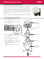
Installation and User Guide
DALI External Light Sensor (329)
The 329 DALI External Light Sensor, when used in conjunction with a Helvar Lighting Router based
controls system, can provide energy savings by adjusting light levels based on the available daylight.
For instance, bright sunlight will raise the overall light level in the rooms of a building. The sensor
will detect this, and the system will reduce the energy levels supplied to the lamps. If the day
then becomes overcast, the system will respond to the lower levels of ambient light by increasing
the energy provided to the lamps. By profiling the building (measuring the daylight contribution
per room) the system can be used to maintain an approximate constant light level, and thereby
reduce energy use.
The 329 is for mounting outdoors. The unit head assembly is waterproof when correctly installed
and mounted vertically, and can tolerate a wide range of operating temperatures and conditions.
1. Assembly and connection
1. Put the sealing gasket in place on the base assembly.
2. Thread the DALI cable through the base asssembly, up
through the sealing gasket.
Head assembly
(sensor head
circuitry and cover)
3. Connect the DALI wires to the connectors of the socket
assembly:
N
DALI +
L0
DALI -
L
Do not connect.
L
+
Function
Connector tabs
DAL
I
Terminal
L0
I-
L
DA
N
4. Check that the sealing gasket is in position, and then
screw the socket assembly into the base assembly (use
the 2 screws supplied).
Socket assembly
5. Mount the base assembly in your chosen outdoor
location. See the ‘Mounting’ section for details.
6. Attach the head assembly to the socket assembly:
-Align the connector tabs with the sockets (note that the
‘N’ tab is larger than the others)
-Push the head assembly down into the socket
assembly.
-Twist the head assembly clockwise to lock it into
position.
Sealing gasket
Base assembly
(including mounting
plate)
DALI
Helvar 329 DALI External Light Sensor: Installation and User Guide
1
2. Mounting
WARNING:
TO AVOID THE POSSIBLE RISK OF LIGHTNING STRIKES, NEVER INSTALL THE
329 DALI EXTERNAL LIGHT SENSOR AT THE HIGHEST POINT ON A BUILDING.
Mounting position
Mount the 329 DALI External Light Sensor outdoors.
Mount the unit vertically.
Any convenient surface may be used as long as the sensor element has a reasonably
unrestricted view of the sky.
Fixing screws
M4 thread or No 8 wood screw: select according to mounting surface.
Use round-head or cheese-head screws. Do not use counter-sunk type screw heads.
Mount the 329 vertically
and outdoors.
Procedure
1. Drill and prepare the screw fixing holes as shown in Fixing Centre Locations diagram in the
Technical Data section.
2. To access the top mounting screw, remove the 329 Head assembly, by twisting the head
assembly anti‑clockwise and lifting it.
3. Screw in the fixing screws.
4. With the bracket located under the top screws, secure the lower screw.
NOTE
Avoid over-tightening the screws as this may weaken or break the bracket material.
Helvar 329 DALI External Light Sensor: Installation and User Guide
2
3. Operation
Light level output
Light level reading output
The external light sensor is calibrated to provide a scaled light level output of 0 to 200 covering the full range of daylight.
The sensitivity of the external light sensor is factory-set and no adjustment is required.
200
180
160
140
120
100
80
60
40
20
0
1
10
100
1000
10,000
Incident light (lux)
100,000
Incident Light
(lux)
Light Level
Equivalent To
Reading Output
Value
≤1
0
2
11
5
26
10
38
20
49
50
65
100
76
200
87
500
102
1,000
114
2,000
125
5,000
140
10,000
152
20,000
163
50,000
178
100,000
190
Darkness
Twilight
Dark day
Overcast day
Full daylight
Bright sunlight
Cleaning the sensor head cover
A build-up of dust and dirt on the clear cover of the sensor head may reduce the efficiency of the light sensor unit.
We recommend that the cover is examined periodically and, if necessary, cleaned with a soft damp cloth. Use a mild detergent
for stubborn marks.
Light sensing angle
Vertical plane: unrestricted viewing angle of 170°.
Horizontal plane: 360° viewing angle.
85º
85º
Helvar 329 DALI External Light Sensor: Installation and User Guide
3
4. Technical Data
Connections
Dimensions (mm)
DALI:
Wire size: 1.0 mm - 2.5 mm
2-core solid, flexible or stranded
Max. length: 300 m @ 2.5 mm2
(part of DALI subnet)
Connector type:
Screw terminals:
N: DALI +
L0:DALI L: Do not connect.
Power cable rating:
All cables must be mains rated
2
2
82
Power
68
DALI power supply:
13 - 22 V
DALI consumption:
10 mA
148
Sensor
Sensor element:
Photodiode matched to human eye
response
Light sensing angle:
When mounted vertically:
85° from vertical;
Horizontal plane: 360°.
Working light range:
1 - 100,000 Lux
Light level reading
output:
0 - 200
93
29
87
Fixing centre locations
(Dimensions in mm)
Mounting
Mounting angle:
Vertical (clear sensor head at top)
Mounting points:
2 x M4 (No. 8 woodscrew) (for fixing
centres see Fig. 2)
Mechanical Data
Ø5
93
81
Overall dimensions (mm): 148 (H) x 82 (W) x 87 (D)
Materials:
Base & mounting bracket Black ABS
Socket & sensor ass’y Black glass-filled nylon
Sensor cover
Toughened acrylic (UV stable)
IP rating:
IP 65
Weight:
250 g
Ø5
29
Operating Conditions
Ambient temperature:
-35°C to +70°C
Relative humidity:
Max 90%, non-condensing
Storage temperature:
-35°C to +70°C
Conformity and Standards
EMC: Emissions
EN 55015
Immunity:
EN 61547
Safety:
EN 60950
Environment:
Complies with WEEE and RoHS
directives
www.helvar.com
Data subject to change without notice
Doc. 7860306, issue 01
04:04:2013