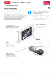
1
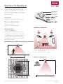
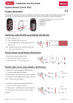
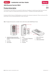
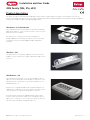
Installation and User Guide
iDIM Family (304, 316, 403)
Product description
The iDim concept is a luminaire based lighting control solution comprising an intelligent sensor (iDim Sense 316), an
interface unit (iDim Solo 403) as well as a range of ballasts (EL-iDim). Combined together they provide a unique standalone
solution for intelligent single-room lighting applications.
iDim Sense – 316 (Standalone)
This luminaire based sensor provides 6 out-of-box standalone
application modes. It connects via its RJ-style connector to the
iDim Solo interface module.
The iDim Sense – 315 (system version) is available to
provide additional functionality as PIR extension sensor and
as network sensor on Helvar Digidim Toolbox and Router
networks.
iDim Solo – 403
The iDim Solo acts as a power supply as well as an interface
module to connect iDim Sense, DALI loads and a range of user
interfaces.
iDim Remote – 304
The iDim Remote allows the user to easily modify the preset
light levels (Constant Light or Fixed Light), recall/store scenes
and activate special functions such as 100-hour burn-in test
and PIR walk-in test.
Another use is to program advanced settings through use of
USB-interface and easy-to-use PC-software. The iDim remote
can also operate as a personal desktop user interface.
As an alternative solution the Digidim Remote (303) can be
used in conjunction with the iDim Sense to modify the preset
light levels, recall/store scenes as well as activate its specials
functions (100-hour burn-in and PIR walk test).
Helvar | Data is subject to change without notice.
www.helvar.com
i
Contents
Product description
i
iDim Sense 316 (Standalone) 1
iDim Solo 403 (Interface Module)
3
iDim Physical Installation
4
Connections5
Connection Methods
5
Mode Selection
7
Mode Selection
ii
9
Typical Mode Setup
10
LED Feedback
13
Ordering Information
14
Technical Data
15
Helvar | Data is subject to change without notice.
www.helvar.com
iDim Sense 316 (Standalone)
The iDim Sense is a luminaire based sensor. It
combines a movement detector (PIR), remote
control receiver (IR) and photocell (CL) in one
enclosure. The manual mode selector allows
the user to easily select one of the 6 out-of-box
application modes.
Photocell (CL)
Movement
detector (PIR)
control
(IR)
Key Features
PIR, photocell (CL) and Infrared control (IR)
Fascia
Easy to select application modes
Clip-on fascia in different colours
Clip-on PIR restrictor
Mode Selector with LED feedback
Mounting Considerations
Installation Notes
Multiple mounting options:
A
B
1) Mount from outside luminaire. ‘Click fit’
2) Mount from inside luminaire. ‘Bracket fit’
3) Combined with louvre adapter. ‘Adapter fit’
Isolate the mains supply before installation.
All cabling must be 230 VAC mains rated when
used outside luminaire.
Movement Detector (PIR) Coverage with Top Down View
85°
3.0 m
A) Do not mount sensor in direct line of artificial light
sources e.g. lamps, uplighters
B) Do not mount sensor in direct sunlight
Photocell Coverage (CL)
4.5 m without restrictor
60°
3m
0m
4.5 m
1m
2m
3.5 m
3m
1
2m
1m
0m
Helvar 304 316 403 iDIM Sense Solo: Installation and User Guide
Doc. D004735 issue 06_062014Update
[12.06.2014]
iDim Sense 316 (Standalone)
Connections
Detector locations: PIR, IR remote control receiver (IR)
and light sensor for constant light (CL)
316 DA – and
DA+ are for PIR
extension use only.
Ø 9.5
10.5
Ø 9.5
Ø 21
1717
mm
1717mm
10.5
55
Dimensions (mm)
iDim Sense without fascia
iDim Sense with fascia
55
25
21.4
12.3
12.3
7.3
2
0.6 - 2.4
20
Helvar 304 316 403 iDIM Sense Solo: Installation and User Guide
58
28.5
Doc. D004735 issue 06_062014Update
[12.06.2014]
iDim Solo 403 (Interface Module)
The iDim Solo is used as an interface module to
connect the iDim Sense (316 Standalone) and iDim
ballasts as well as user interfaces. Additionally, the iDim
Solo can be used as a DALI power supply unit (PSU).
The unit is housed in a standard ballast-style enclosure
making it easy to assemble.
Key Features
• Power capability: 64 mA (DALI 1), 32 mA (DALI 2) or
96 mA when operating in parallel
• 2 × DALI outputs
• 2 × Switch control inputs
iDim Solo as Interface Module
• iDim Sense connection (RJ style, 4P4C)
• Mains connection
iDim Sense
(Master)
Installation Notes
• All cabling must be 230 VAC mains rated and
considered live when operating outside luminaire
230 V
RJ Style Cable
( 4P4C )
iDim Solo
• Isolate the mains supply before installation
L
• The external mains supply to the unit must be
protected.
www.helvar.com
0,5...1,5
iDim Solo
Interface Module
com
9 mm
100 - 240 V 50 - 60 Hz
40 mA
ta: 10°C...50°C
tc: 75°C
SW 2
com
• Install in a restricted access location only, e.g.
luminaire housing
iDim Sense
tc
N
SW 1
DALI 1
64 mA
+
-
DALI 2
32 mA
+
-
Switch
Control
DALI 2
32 mA
DA (+)
DA (-)
iDim Ballasts
DALI 1
64 mA
DA (+)
DA (-)
iDim Solo as a Power Supply Unit (PSU)
...
DA )+(
DA )-(
DA )+(
DA )-(
iDim Ballasts
230 V
L
N
SW 1
com
SW 2
com
100 - 240 V 50 - 60 Hz
40 mA
ta: 10°C...50°C
tc: 75°C
9 mm
16
DALI 1
64 mA
+
-
DALI 2
32 mA
+
-
DA
DA
DALI 1
64 mA
)+(
)-(
...
DA )+(
DA )-(
DA )+(
DA )-(
DALI 2
32 mA
DA )+(
DA )-(
Helvar 304 316 403 iDIM Sense Solo: Installation and User Guide
0,5...1,5
iDim Solo
Interface Module
iDim Solo
3
iDim Sense
tc
www.helvar.com
Doc. D004735 issue 06_062014Update
[12.06.2014]
iDim Physical Installation
Below you will find the recommended methods for installing the iDim Sense and Solo into your luminaire.
3.1 iDim Sense Installation
There are 3 possible ways for mounting the iDim Sense to the luminaire.
External Mounting
1. Cut opening in luminaire 56.5 × 26 mm ± 0.25 mm.
2. Click Fascia to iDim Sense.
3. Click iDim Sense into luminaire.
1
26 mm
3
Note: Opening dimensions are applicable for a luminaire
with a housing thickness of 0.6 mm to 2.4 mm max.
56.5 mm
2
Fabricate Louvre Adapter
1. F
abricate a louvre adapter to fit at either end of the
luminaire. (Opening dimensions: 56.5 × 26 mm ± 0.25 mm.)
2. Click iDim Sense into louvre adapter opening.
1
3. Fit complete assembly to louvre.
3
2
Internal Mounting
1. Cut three holes in the luminaire.
(See adjacent diagram for dimensions).
2. Insert iDim Sense from inside the luminaire.
3. Fabricate a bracket to secure iDim Sense in place.
Note: Fascia not required when mounting the iDim Sense
internally.
3.2 iDim Solo Installation
Use these screw types when mounting the iDim Solo:
• Pan head Machine Screw M4
4.2 mm
L
N
• Pan head Self Tapping Screw No. 8
SW 1
www.helv
iDim Solo
Interface M
100 - 240 V 50
SW 2 40 mA
ta: 10°C...50°C
com tc: 75°C
3.3 Mounting the optional PIR Restrictor
X
1. Select a mode before mounting PIR restrictor.
2. Position PIR restrictor to cover the area to be hidden.
3. Push PIR restrictor over the mode selector.
1
Caution: Do NOT adjust PIR restrictor while it is attached to
the iDim Sense.
3
2
Helvar 304 316 403 iDIM Sense Solo: Installation and User Guide
DALI 1
DALI 2
Note: Countersunk screws should not be used.
4
iDim Sense
com
Doc. D004735 issue 06_062014Update
[12.06.2014]
Connections
Cable Requirements
Note 1: DALI cable must be mains rated and the maximum voltage drop along the length of the cable must not exceed 2 V.
Note 2: RJ cabling used outside of luminaire fitting must be mains rated. Use Alpha 1174C or 6642.
Connection
Cable Type
iDim Solo DALI
1.0 mm to 1.5 mm (recommended)
max. 300 m @ 1.5 mm2
iDim Sense (316
Standalone)
RJ style 4P4C connector (crossover)
max. 3 m between iDim Solo and iDim Sense
Switch Control
0.5 mm2 to 1.5 mm2 (recommended)
max. 50 m
Mains Supply Cable
0.5 mm to 1.5 mm
-
2
2
Cable Length
2
2
Connection Methods
Important! iDim Solos contain DALI power supplies and therefore must always be connected DA+ to DA+ and DA–
to DA–.
4.1 iDim Standalone
The adjacent diagram shows the iDim Sense (316), iDim
Solo and iDim ballasts connected as a basic standalone
system.
RJ Style
4P4C Cable
iDim Sense (316)
(Master)
230 V
iDim Solo
L
iDim Sense
tc
N
www.helvar.com
SW 1
com
SW 2
com
0,5...1,5
iDim Solo
Interface Module
9 mm
100 - 240 V 50 - 60 Hz
40 mA
ta: 10°C...50°C
tc: 75°C
16
DALI 1
64 mA
+
-
DALI 2
32 mA
+
-
DALI 2
32 mA
DA (+)
DA (-)
iDim Ballasts
DALI 1
64 mA
DA (+)
DA (-)
4.2 iDim Networked
Important! Only available with iDim Sense 315.
iDim Ballasts
DIGIDIM 910 Router
)+(
)-(
iDim Sense
(315)
DA
DA
• T
he adjacent diagram shows the iDim Sense 315
(system) connected directly to a Helvar 910/920 router
via the push wire DALI connectors located on the
reverse of the device.
In luminaire
Power/Status
Dali 1
910
Dali 2
Digidim Router
(85 to 264)VAC
• iDim Sense 315 can also be used in conjunction with
Helvar Digidim Toolbox systems.
• Using the iDim Sense 315 with a 910 or 920 router will
cause the iDim Sense mode selector to be ignored. All
configuration is done via Designer software where the
iDim Sense 315 behaves like a 312 Multisensor.
5
Helvar 304 316 403 iDIM Sense Solo: Installation and User Guide
L
N
E
SC
Link/Activity
www.helvar.com
DALI11
Dali
DA- DA+
Dali 2
DA- DA+
2 Wire
DALI Cable
DIGIDIM
Panels
DIGIDIM
303 Remote
Control
Doc. D004735 issue 06_062014Update
[12.06.2014]
4.3 iDim Solo as a PSU
• The adjacent diagram shows the iDim Solo working as
a PSU.
• Outputs are paralleled to provide 96 mA of power.
...
• RJ 4P4C Connector and Switch Inputs are not used
when iDim Solo operates as a DALI power supply.
Note: For maximum number of ballasts, see
manufacturer data.
DA
DA
iDim Ballasts
230 V
)+(
)-(
DA
DA
)+(
)-(
DA
DA
)+(
)-(
Not
used
L
Not
used
iDim Sense
tc
N
www.helvar.com
SW 1
com
SW 2
com
0,5...1,5
iDim Solo
Interface Module
9 mm
100 - 240 V 50 - 60 Hz
40 mA
ta: 10°C...50°C
tc: 75°C
16
DALI 1
64 mA
+
-
DALI 2
32 mA
+
-
DALI 1
64 mA
Paralleled
DALI 2
32 mA
iDim Solo
4.4 Device Combinations
• T
he adjacent diagram shows all possible device
combinations.
• S
ee table 1 for possible system device capacities using
the iDim Sense and Solo.
Multisensor 312 ,
(PIR extension)
• SW1 and SW 2, are switch-control inputs giving scene 1/
off and level control of DALI 1 and 2 respectively.
• PIR movement generates scene 1 when lights are Off or
extends the scene already selected when lights are on.
iDim Sense (316)
(Master)
RJ Style
DA
DA
4P4C Cable
DALI 1
64 mA
230 V
iDim Sense 315 or 316
(PIR extension)
)+(
)-(
iDim Ballasts
L
N
SW 1
com
SW 2
com
iDim Sense
tc
www.helvar.com
0,5...1,5
iDim Solo
Interface Module
100 - 240 V 50 - 60 Hz
40 mA
ta: 10°C...50°C
tc: 75°C
Switch
Control
9 mm
16
DALI 1
64 mA
+
-
DALI 2
32 mA
+
-
DALI 2
32 mA
DA )+(
DA )-(
iDim Solo
Input 1
DIGIDIM
Panels
Sw1 Sw 2
Switch Control
via DIGIDIM 444
Input 2
Table 1: iDim Sense and iDim Solo device capacity combinations.
iDim Sense 316
iDim ballast
Ceiling multisensor
(Master)
2 mA
(PIR extension)
15 mA
+ iDim Solo
DALI 1
(64 mA -10 mA)**
DALI 2
(32 mA)
iDim Sense 315
or 316
(PIR extension)
10 mA
DIGIDIM
button panel
10 mA
up to 27 *
up to 3 *
up to 5 *
up to 5 *
up to 16 *
up to 2 *
up to 3 *
up to 3 *
* The total number of devices depends on the overall combination.
** 10 mA is consumed by one iDim Sense Master unit.
iDim Solos contain power supplies. Always ensure you do not exceed a current of 250 mA on any DALI connection.
6
Helvar 304 316 403 iDIM Sense Solo: Installation and User Guide
Doc. D004735 issue 06_062014Update
[12.06.2014]
Mode Selection
There are 6 default modes which can be set by turning the mode selector located on the sensor unit.
1
1) To locate mode 1 (Classroom mode), rotate the mode selector counterclockwise until it stops.
2
6
2) If changing modes during power on, the red LED will blink 1 to 6 times to indicate mode
selected.
Note: Ensure that the PIR restrictor is not attached to the iDim Sense during mode selection.
3
5
4
Table 2: Default iDim
configuration:
CLASS-
SINGLE
OPEN PLAN
CORRIDOR
CORRIDOR
MEETING
ROOM
OFFICE
OFFICE
LINK
HOLD
ROOM
15 min
15 min
15 min
5 min
15 min
15 min
Transition
1 min
1 min
60 min
30 min
1 min
1 min
Timeout (level)
(20 %)
(20 %)
(20 %)
(20 %)
(20 %)
(20 %)
Enabled /
Disabled
Enabled
Enabled
Enabled
Enabled
Disabled
Disabled
Enabled /
Manual On
Enabled
Auto On
Enabled
Auto On
Enabled
Auto On
Enabled
Auto On
Enabled
Manual On
Enabled
Disabled
Auto Off
Auto Off
Auto Off
Auto Off
Auto Off
Auto Off
DALI 1
CL 1
CL 1
CL 1
FL (100 %) 1
CL
CL
DALI 2
Offset1
Offset1
Offset 1
FL (100 %) 1
DALI 1
CL 1
CL 1
CL 1
FL (70 %) 1
DALI 2
Offset 1
Offset 1
Offset 1
FL (70 %) 1
DALI 1
FL (100 %)
FL (100 %)
FL (100 %)
FL (40 %) 1
DALI 2
FL (100 %)
FL (100 %)
FL (100 %)
FL (40 %) 1
DALI 1
FL (40 %)
FL (40 %)
FL (40 %)
FL (10 %) 1
DALI 2
FL (40 %)
FL (40 %)
FL (40 %)
FL (10 %) 1
Occupancy
TIMING
& LEVEL
Timeout
When On
BRIGHT OUT
When Off
PRESENCE
ABSENCE
iDim
Controller
Scene 1
iDim
Controller
Scene 2
iDim
Controller
Scene 3
iDim
Controller
Scene 4
Link to
See notes
Corridor 2
below 3
CL
-
Link to
Corridor 2
FL (100 %)
Link to
Corridor 2
FL (40 %)
Link to
Corridor 2
FL (100 %)
FL (0 %)
FL (40 %)
FL (20 %)
Table Information
In this table ‘iDim Controller’ refers to Remote Control, Switches and Panels unless specified.
1
iDim Solo SW1 and SW 2 are switch-control inputs. In modes where DALI 2 is ‘offset’ from DALI 1 and in Corridor Hold
mode, they control the level of both DALI 1 and DALI 2.
2
In Corridor Hold (Mode 5) DALI 2 is only used to connect an office to the corridor.
3
In Meeting Room (Mode 6), iDim Solo SW1 input operates DALI 1 CL / Off and SW2 input operates DALI 2 FL (100 %) / Off.
As SW1 is located at the entrance of a room, switching off SW1 will cause both DALI 1 and DALI 2 circuits to go off.
General Information
Long key presses of a controller give Up / Down level control of DALI 1 and DALI 2. They operate independently except
when in CL + Offset scenes where they operate together.
Short key presses of a switch give Scene 1 / Off control of DALI 1 and DALI 2 together except in Meeting Room (Mode 6).
(Refer to point 3 above).
7
Helvar 304 316 403 iDIM Sense Solo: Installation and User Guide
Doc. D004735 issue 06_062014Update
[12.06.2014]
The following settings can be modified using the Helvar iDim Studio software:
Occupancy Timeout: Time when PIR detects no movement and maintains level before moving to transition timeout (e.g. 15 mins).
Transition Timeout: Lights are lowered to energy saving level for a specific time before switching off (e.g. 60 secs).
For example:
Relative
light level (%)
e.g 15 mins
e.g. 60 secs
Time
Exit
Entry
Presence
Presence Detection enables PIR movement to switch on lights. This function can be either enabled or disabled.
Absence
Absence Detection enables automatic switch off of lights. This function can be either enabled or disabled.
iDim Remote / Controller Scenes 1– 4
DALI 1 and DALI 2 outputs operate as a combination of Constant Light (CL), Fixed Light (FL) and Offset. These terms are
discussed in greater detail below. The Constant Light and Fixed Light level settings can be modified using the iDim
Remote Control or a DIGIDIM button panel. For further information on these settings, see iDim Remote User Manual
(D004744).
Constant Light
Constant Light (CL) is a method of automatically controlling the level of the system’s lights by utilising the natural light of
an area and adapting the light level accordingly. This setting is configurable using the iDim Remote however it is important
to remember constant light should always be configured in a darkended room or at dusk to avoid natural light affecting the
configuration of the target level.
Fixed Light
Fixed Light is where the load output is NOT adjusted by the Light Sensor. Lights will remain at at a certain level unless
altered.
Offset
The Offset figure is the difference between DALI 1 and DALI 2. When working with CL, the offset amount will maintain
the level difference no matter how lighting condtions change.
Constant Light (CL) & Fixed Light (FL)
The adjacent example shows DALI 2 operating with
Fixed Light settings. Only DALI 1 (Constant Light)
levels increase /decrease subject to natural light
changes.
8
Helvar 304 316 403 iDIM Sense Solo: Installation and User Guide
Doc. D004735 issue 06_062014Update
[12.06.2014]
Mode Selection
Constant Light (CL) & Offset
The adjacent example shows the default Offset of 20 %.
When more natural light is detected by the Constant Light
sensor, DALI 2 (Offset) will lower the light level at the same
rate as DALI 1 (CL) while maintaining the 20 % gap.
Bright Out
Bright out is an optional feature of constant light operation that allows further energy saving by reducing light level
during times of adequate natural light. By default, bright out settings for all preset iDim modes are enabled. Bright
out settings can be either enabled or disabled in iDim Studio.
Bright Out - When Off: If lights are off and there is enough natural light, the lights will go to power save level (default 10 %)
when switched on.
Bright Out - When On: If lights are on and there is enough natural light, the lights will reduce to power save level after
10 mins.
Bright out - Upper threshold: Specific threshold above the target light level. Configurable using iDim Studio software.
Bright out - Lower threshold: Specific threshold below the target light level. Configurable using iDim Studio software.
For example:
Note: If the light level is
ever less than the power
save level, then it will stay at
the lower level and not go to
the power save level.
If necessary, the power save
level can be set to off (0 %)
via iDim Studio Editor.
When scene is selected/triggered: Lights go to power save level (10 % by default) if natural light is above the upper level
threshold. If light level goes below the lower level threshold, then the lights revert to Constant Light.
When scene is already selected: Lights reduce to power save level if natural light is above the upper level threshold for
more than 10 minutes. If the light level goes below the lower level threshold, then the lights revert to Constant Light.
Power Up Procedure
When lights are powered up, they will go to 100 % for 5 minutes. If there is no PIR movement within this time, they will go
off (0 %).
If movement is detected anytime during this period, then the system will start to operate as normal. As this is a standard safety
feature it is NOT configurable in iDim Studio.
User Defined Mode
iDim Sense enters User Defined Mode as soon as scenes and settings are stored via the iDim Remote Control.
When in User Defined Mode the iDim Sense Mode Selector ring will be ignored.
To leave User Defined Mode and reset to default settings at any time, hold button 3 + 4 on the Remote for 10 seconds.
9
Helvar 304 316 403 iDIM Sense Solo: Installation and User Guide
Doc. D004735 issue 06_062014Update
[12.06.2014]
Typical Mode Setup
Please see below for suggested installation methods for each of the six modes.
Note: The following modes show DALI 1 and DALI 2 when scene 1 is selected. See table 2 for further information.
Key:
iDim Sense
Panels:
iDim Solo
Control
iDim Ballasts
(Switch) or
(7 button panel)
iDim Remote
6.1 Classroom Setup (Mode 1)
Presence Detection : Disabled, Absence Checking : Enabled, Bright Out : Enabled, Occupancy Timeout : 15 minutes,
Transition : 60 seconds @ 20 % , Exit delay : 90 seconds
Note: For an alternative
classroom setup please
refer to 6.6 Meeting Room
(Alternative Classroom).
6.2 Single Office Setup (Mode 2)
Presence Detection : Enabled, Absence Checking : Enabled, Bright Out : Enabled, Occupancy Timeout : 15 minutes,
Transition : 60 seconds @ 20 % , Exit delay : 90 seconds
(Optional)
DALI 2
(OFFSET)
(Optional)
DALI 1
(CL)
10
Helvar 304 316 403 iDIM Sense Solo: Installation and User Guide
Doc. D004735 issue 06_062014Update
[12.06.2014]
6.3 Open Plan Office Setup (Mode 3)
Presence Detection : Enabled, Absence Checking : Enabled, Bright Out : Enabled, Occupancy Timeout : 15 minutes,
Transition : 60 minutes @ 20 % , Exit delay : 90 seconds
DALI 1 (CL)
DALI 2
(OFFSET)
DALI 2 (OFFSET)
DALI 2 (OFFSET)
DALI 1 (CL)
DALI 1 (CL)
DALI 1 (CL)
DALI 1 (CL)
6.4 Corridor Link Setup (Mode 4)
Presence Detection : Enabled, Absence Checking : Enabled, Bright Out : Enabled, Occupancy Timeout : 5 minutes,
Transition : 30 minutes @ 20 % , Exit delay : 90 seconds
Note: The corridor is wired DALI (1 or 2) to DALI (1 or 2) along the corridor. Corridor loads and controls can be
connected to either DALI output. The contributing iDim Solo supplies must not exceed 250 mA on any DALI connection.
iDim Solos contain DALI power supplies and therefore must always be connected DA+ to DA+ and DA– to DA–.
11
Helvar 304 316 403 iDIM Sense Solo: Installation and User Guide
Doc. D004735 issue 06_062014Update
[12.06.2014]
6.5 Corridor Hold Setup
(Mode 5) +
(Mode 4 for corridor wiring)
Presence Detection : Enabled, Absence Checking : Enabled, Bright Out : Enabled, Occupancy Timeout : 15 minutes,
Transition : 60 seconds @ 20 % , Exit delay : 90 seconds
Mode 4
Mode 5
Note: The corridor will remain lit when any of the lights are on in single cell offices.
Office loads and controls must be connected to the DALI 1 output (64 mA current limit – limited by Solo DALI 1 supply).
The DALI 2 output is only for connection from the office to the corridor.
iDim Solos contain DALI power supplies and therefore must always be connected DA+ to DA+ and DA– to DA–.
6.6 Meeting Room (Alternative Classroom)
(Mode 6)
Presence Detection : Disabled, Absence Checking : Enabled, Bright Out : Enabled, Occupancy Timeout : 15 minutes,
Transition : 60 seconds @ 20 % , Exit delay : 90 seconds
SW 2
SW 1
Note: iDim Solo SW1 input operates DALI 1 CL / Off and SW2 input operates DALI 2 FL (100 %) / Off.
As SW1 is located at the entrance of a room, switching off SW1 will cause both DALI 1 and DALI 2 circuits to go off.
12
Helvar 304 316 403 iDIM Sense Solo: Installation and User Guide
Doc. D004735 issue 06_062014Update
[12.06.2014]
LED Feedback
The iDim Sense contains 2 LEDs, red and green, that provide user feedback for different functions.
Function
LED Flash Feedback
User Defined Mode Selected*
Mode Unmodified
Mode 1 Selected
(Classroom Mode)
Mode 2 Selected
(Single Office)
Mode 3 Selected
(Open Plan Office)
Mode 4 Selected
(Corridor Link)
Mode 5 Selected
(Corridor Hold)
Mode 6 Selected
(Meeting Room)
250
250
msms
250
ms
250
ms
250
ms
250
ms
250
ms
250
ms
250
ms
250
ms
250
ms
250
ms
250
ms
250
ms
250
ms
250
ms
250
ms
250
ms
250
ms
250
ms
250
ms
250
ms
250
ms
250
250
msms
250
250
msms
250
250
msms
250
250
msms
250
250
msms
250
250
ms
ms
250
250
msms
250
250
msms
250
250
msms
250
250
msms
250
250
msms
250
250
msms
250
250
msms
250
250
msms
250
250
msms
250
250
msms
250
250
msms
250
250
msms
250
250
msms
PIR Walk Test Mode
Sequence repeats until walk test is
complete.
100 hour Burn-In Mode
Sequence repeats until burn-in is
complete.
DALI Errors
1 sec
Typically follows a PIR detection.
Data received from IR Remote
Enabling / Disabling of IR Receiver
250
ms
250
ms
250
ms
30 sec
250
ms
250
ms
250
ms
...
1 sec
250
ms
30 sec
250
ms
Sequence repeats until error clears.
Change from unoccupied to occupied
1 sec
250
250
msms
250
ms
...
...
125
ms
125
ms
125
ms
Successful Scene Store
625 ms
Failed Scene Store
625 ms
Successful Upload from IR Remote
Failed Upload from IR Remote
625 ms
125
ms
125
ms
625 ms
125
ms
125
ms
125
ms
125
ms
125
ms
125
ms
Note: iDim Sense LED feedback flashes apply to all iDim units of v5.3 and onwards
* To leave User Defined mode and reset iDim Sense to default settings at any time, hold button 3 + 4 on the iDim Remote
Control for 10 seconds while the remote is in ‘Special function mode’.
13
Helvar 304 316 403 iDIM Sense Solo: Installation and User Guide
Doc. D004735 issue 06_062014Update
[12.06.2014]
Ordering Information
A large selection of accessories can be used in conjunction with the iDim family to support your individual lighting needs.
Sensors & Interface Module
Accessories
312 Multisensor
50630 iDim Cable (Pack of 30)
(PIR extension only)
50cm RJ-style cable
(4P4C crossover)
315 iDim Sense
(System & Standalone)
iDim Fascia
316 iDim Sense
white or grey supplied as
standard with iDim Sense other colours optional.
(Standalone)
403 iDim Solo
Digidim 444 Mini Input Unit
(Interface Module)
User Interfaces
304 iDim Remote
Software
Dedicated iDim remote featuring
USB port for advanced settings and
PC desktop control.
Digidim ‘iDim Ready’ Panels
121, 122, 124, 125, 126
iDim Demonstrator
Freeware to simulate the iDim
standalone system operation for
training purposes.
iDim Studio Editor
Digidim 303 IR Remote Control.
Standard remote control to modify
target light levels, scene recall /
store and recall test functions.
Freeware that allows to create either
graphical user interface applets for the
iDim Remote, or modify advanced iDim
system
settings.
For detailed information about all Helvar products, please visit www.helvar.com.
Product Code
Description
Package Dimensions
315
Single packaged iDim Sense (System & Standalone), including white and grey
fascia and PIR restrictor.
65 mm × 34 mm × 30 mm
316
Single packaged iDim Sense (Standalone), including white and grey fascia and
PIR restrictor.
65 mm × 34 mm × 30 mm
31630W
Tray of 30 pieces non-packaged iDim Sense (Standalone), including 30 pieces
white fascia and PIR restrictor.
395 mm × 232 mm × 52 mm
31630G
Tray of 30 pieces non-packaged iDim Sense (Standalone), including 30 pieces
grey fascia and PIR restrictor.
395 mm × 232 mm × 52 mm
403
Single packaged iDim Solo Interface Module.
123 mm × 32 mm × 22 mm
40330
Tray of 30 pieces non-packaged iDim Solo Interface Modules.
367 mm × 309 mm × 30 mm
50630
14
Set of 30 pieces iDim Cable, RJ-style connectors (4P4C) each 500mm length.
Helvar 304 316 403 iDIM Sense Solo: Installation and User Guide
-
Doc. D004735 issue 06_062014Update
[12.06.2014]
Technical Data
Connections
PC to remote:
Connections
USB 2.0 A Cable to Mini B Cable
Power
Power supply:
2 × AAA (LR03) 1.5 V batteries
RJ Style 4P4C
Connector
Range
Operating range:
Approx. 10 m
Operating frequency:
36 kHz
DALI 1
DALI 2
DA (+) DA (-) DA (+) DA (-)
iDim Sense
(316)
0.5 - 1.5 mm
2
9 mm
+
DALI 2
32 mA
16
9 mm
com
SW
SW 22
iDim Solo
Interface Module
2 × No 6 – ¾” (3.5 mm × 20 mm)
pan pozi head screws
100 - 240 V 50 - 60 Hz
40 mA
ta: 10°C...50°C
tc: 75°C
Bracket screws:
com
40 g
SW 1
SW
SW 12
Traffic White (RAL 9016)
Weight:
tc
Colour (housing):
www.helvar.com
Non-flammable polycarbonate,
halogen free
N
Material (housing):
L
59 mm × 21 mm × 110 mm
L
N
Dimensions:
0,5...1,5
Mechanical data
DALI 1
64 mA
iDim Sense
Infrared remote control: Modify preset light levels
(Constant light or fixed light);
Scene store and recall;
Activate special test functions
+
-
Remote control functions
Operating conditions
0.5 - 1.5 mm
Ambient temperature:
0 °C to +40 °C
Relative humidity:
Max. 90 %, non-condensing
Storage temperature:
–10 °C to +70 °C
9 mm
L
N
Conformity and standards
EMC emission:
EN 61000–6–3
EMC immunity:
EN 61006–1
Safety:
EN 60950–1
Environment:
Complies with WEEE and RoHS
directives
2
SW
SW
Dimensions
L
N
30 mm
SW 1
com
SW 2
com
iDim Sense
tc
www.helvar.com
0,5...1,5
iDim Solo
Interface Module
100 - 240 V 50 - 60 Hz
40 mA
ta: 10°C...50°C
tc: 75°C
9 mm
16
DALI 1
64 mA
DALI 2
32 mA
+
+
-
4.2 mm
102 mm
112 mm
21 mm
121 mm
15
Helvar 304 316 403 iDIM Sense Solo: Installation and User Guide
Doc. D004735 issue 06_062014Update
[12.06.2014]