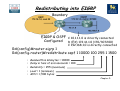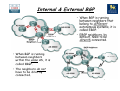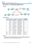
1
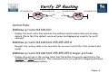
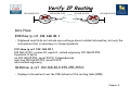
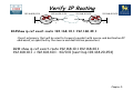
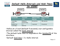
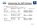
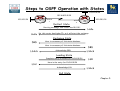
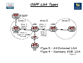
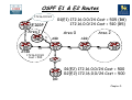
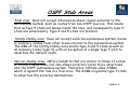
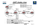
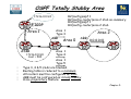
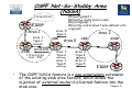
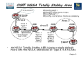
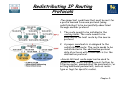
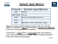
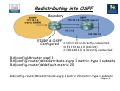
Chapter 5 – Maintaining &
Troubleshooting Routing Solutions
Objectives
• Describe EIGRP operation & troubleshooting
techniques.
• Describe OSPF operation & troubleshooting
techniques.
• Describe BGP operation & troubleshooting
techniques.
• Describe route redistribution operation &
troubleshooting techniques.
Chapter 5
Packet Forwarding
IP Address: 1.2
MAC: A
L3 Packet
L2
Frame
Dest
3.3
Dest
C
Source
1.2
Source
A
Dest
3.3
Dest
H
L3 Packet
L2
Frame
IP Address:1.1
MAC: C
Source
1.2
Source
F
IP Address:3.1
MAC: F
Switch
B
A
IP Address: 3.2
MAC: G
Switch
R1
R2
C
IP Address:2.1 IP Address:2.2
MAC: D
MAC: E
IP Address:1.3
MAC: B
L3 Packet
L2
Frame
Dest
3.3
Dest
E
•Executing different table lookups and combining the
information to construct a frame every time a packet
needs to be routed is an inefficient approach to
forwarding IP packets.
•To improve this process and increase the performance
of IP packet switching operations, Cisco routers employ
CEF.
Source
1.2
Source
D
IP Address:3.3
MAC: H
Identify the correct destination and
source addresses at points A, B & C
If 1.2 sends a packet to 3.3
Chapter 5
Verify IP Routing
192.168.10.0/24
192.168.20.0/24
.254
Fa0/0
.1
R1
S0/0/0
.1
192.168.30.0/24
192.168.40.0/24
.254
S0/0/0
.1
R2
Fa0/0
.1
Control Plane:
R1#show ip route 192.168.40.1
• Display the best route that matches the address and all associated control plane
details. (Note that the default route will never be displayed as a match for an IP
address).
R1#show ip route 192.168.40.0 255.255.255.0
• Request the routing table to be searched for an exact match (for that network and
mask).
R1#show ip route 192.168.40.0 255.255.255.0 longer-prefixes
• Display all prefixes in the routing table that fall within the prefix specified by the
network and mask parameters. This command can be very useful to diagnose problems
related to route summarization.
Chapter 5
Verify IP Routing
192.168.20.0/24
192.168.10.0/24
.254
Fa0/0
.1
R1
S0/0/0
.1
192.168.30.0/24
192.168.40.0/24
.254
S0/0/0
.1
R2
Fa0/0
.1
Data Plane:
R1#show ip cef 192.168.40.1
• Displayed results do not include any routing protocol related information, but only the
information that is necessary to forward packets.
R1# show ip cef 192.168.40.1
192.168.1.0/24, version 42, epoch 0, cached adjacency 192.168.20.254
0 packets, 0 bytes
via 192.168.20.254, serial 0/0/0, 0 dependencies
next hop 192.168.20.254, serial 0/0/0,
valid cached adjacency
R1#show ip cef 192.168.40.0 255.255.255.0
• Displays information from the FIB instead of the routing table (RIB).
Chapter 5
Verify IP Routing
192.168.10.0/24
192.168.20.0/24
.254
Fa0/0
.1
R1
S0/0/0
.1
192.168.30.0/24
192.168.40.0/24
.254
S0/0/0
.1
R2
Fa0/0
.1
R1#show ip cef exact-route 192.168.10.1 192.168.40.1
•Exact adjacency that will be used to forward a packet with source and destination IP
addresses, as specified by the source and destination parameters.
R2# show ip cef exact-route 192.168.10.1 192.168.40.1
192.168.10.1 -> 192.168.40.1 : S0/0/0 (next hop 192.168.20.254)
Chapter 5
EIGRP Features
• EIGRP is an advanced distance vector routing protocol
but also acts as a link-state protocol in the way that it
updates neighbors and maintains routing information.
• The following are advantages of EIGRP over simple
distance vector protocols:
•Rapid convergence
•Efficient use of bandwidth
•Support for VLSM and CIDR
•Multiple network layer support
•Independence from routed protocols
•Routing update Authentication
Chapter 5
Default Hello Intervals and Hold Times
for EIGRP
Hello?
R1
S0/0/0
Hello?
S0/0/0
R2
•Hellos at a fixed (default 5 seconds), but configurable
interval called the hello interval.
•The default hello interval depends on the bandwidth of the
interface.
•Default hold time = 3 x hello interval.
Chapter 5
EIGRP Tables
Router C’s tables:
Topology
Chapter 5
EIGRP Neighbor Table
•Adjacency information is stored within a neighbour table.
The router must have an entry for each neighbouring
router in order to function.
•For an adjacency to form, EIGRP neighbours must share
the same subnet, AS number, k-values and authentication
parameters
Chapter 5
EIGRP Topology Table
•When the router dynamically discovers a new neighbour, it sends an
update about the routes that it knows to its new neighbour.
•These updates populate the topology table, which contains all the
destinations advertised by neighbouring routers.
R1#show ip eigrp topology
IP-EIGRP Topology Table for AS(100)/ID(192.168.1.101)
Codes: P - Passive, A - Active, U - Update, Q - Query, R - Reply,
r - reply Status, s - sia Status
P 192.168.1.96/27, 1 successors, FD is 40512000
via Connected, Serial0/0/1
P 192.168.1.0/24, 1 successors, FD is 40512000
via Summary (40512000/0), Null0
P 172.16.0.0/16, 1 successors, FD is 28160
via Summary (28160/0), Null0
P 172.16.1.0/24, 1 successors, FD is 28160
via Connected, FastEthernet0/0
P 172.17.0.0/16, 1 successors, FD is 40514560
via 192.168.1.102 (40514560/28160), Serial0/0/1
•The topology table is updated when a directly connected route or
interface changes or when a neighbouring router reports a change to a
route.
Chapter 5
EIGRP Topology Table
• To view detailed information about the metrics of a specific entry in
the topology table, add the optional parameter [network] to the show
ip eigrp topology command:
Chapter 5
EIGRP Routing Table
R1#show ip route eigrp
D
172.17.0.0/16 [90/40514560] via 192.168.1.102, 00:07:01, Serial0/0/1
172.16.0.0/16 is variably subnetted, 2 subnets, 2 masks
D
172.16.0.0/16 is a summary, 00:05:13, Null0
192.168.1.0/24 is variably subnetted, 2 subnets, 2 masks
D
192.168.1.0/24 is a summary, 00:05:13, Null0
R1#show ip route
<output omitted>
Gateway of last resort is not set
D
172.17.0.0/16 [90/40514560] via 192.168.1.102, 00:06:55, Serial0/0/1
172.16.0.0/16 is variably subnetted, 2 subnets, 2 masks
D
172.16.0.0/16 is a summary, 00:05:07, Null0
C
172.16.1.0/24 is directly connected, FastEthernet0/0
192.168.1.0/24 is variably subnetted, 2 subnets, 2 masks
C
192.168.1.96/27 is directly connected, Serial0/0/1
D
192.168.1.0/24 is a summary, 00:05:07, Null0
Chapter 5
Monitoring EIGRP
• The following debug commands can be used to observe the
transmission and reception of EIGRP packets and the exchange of
routing information:
1. debug ip routing: This command is not specific to EIGRP, but
displays any changes that are made to the routing table, such as
installation or removal of routes. This can be useful to diagnose
routing protocol instabilities.
2. debug eigrp packets: This command displays the transmission and
reception of EIGRP packets. Either all packets can be displayed, or
packets of a particular type, such as hellos, updates, queries, and
replies can be selected.
3. debug ip eigrp: This command displays EIGRP routing events, such
as updates, queries, and replies sent to or received from neighbours.
Focuses on the routing information contained in the packets and the
actions that EIGRP takes as a result of the information received.
Chapter 5
Monitoring EIGRP
192.168.10.0/24
Fa0/0
.1
192.168.40.0/24
192.168.20.0/30
R1
EIGRP 100
S0/0/0
.1
S0/0/0
.2
R2
Fa0/0
.1
EIGRP 100
• The output of the debug eigrp packets and debug ip eigrp commands
can be further limited by use of two additional debug commands:
R1#debug ip eigrp neighbor 100 192.168.20.2
• By imposing this extra condition, the output of the debug eigrp packets and debug ip
eigrp commands will be limited to information that is associated with the specified
neighbour.
R1#debug ip eigrp 100 192.168.20.0 255.255.255.252
• By imposing this extra condition, the output of the debug eigrp packets and debug ip
eigrp commands will be limited to information that is associated with the network
specified by the network and mask options.
Chapter 5
Features of OSPF
• OSPF is link-state routing protocol, so is not susceptible to routing
loops, split-horizon, and other issues.
• Generate routing updates only when a change occurs in the network
topology. When a link-state changes, the device that detected the
change creates a link-state advertisement (LSA) concerning that link.
• LSAs are reliable; there is a method for acknowledging the delivery
of LSAs.
• LSAs are flooded throughout the area (or throughout the domain if
there is only one area).
• LSAs have a sequence number and a set lifetime so that each router
recognizes that it has the most up-to-date version of the LSA.
Chapter 5
OSPF Router Types
Chapter 5
Link State Advertisements (LSA)
Link-state information must be synchronized between
routers, which means the following:
• LSAs are reliable; there is a method for acknowledging
the delivery of LSAs.
• LSAs are flooded throughout the area (or throughout the
domain if there is only one area).
• LSAs have a sequence number and a set lifetime so that
each router recognizes that it has the most up-to-date
version of the LSA.
• LSAs are periodically refreshed to confirm topology
information before the information ages out of the linkstate database.
Chapter 5
OSPF Neighbour Relationship
• OSPF discovers neighbours through the transmission of periodic
Hello packets. Two routers will become neighbours only if the
following parameters match in the Hello packets:
1.Hello and dead timers: Neighbours must use the same Hello and dead
time. OSPF area number: Two routers will become neighbours on a link
only if they both consider that link to be in the same area.
2.OSPF area type: Neighbours must both consider the area to be the
same type of area (normal, stub, or not-so-stubby area [NSSA]).
3.IP subnet and subnet mask: Two routers will not become neighbours if
they are not on the same subnet. The exception to this rule is on a
point-to-point link, where the subnet mask is not verified.
4.Authentication type and authentication data: Neighbours must use the
same authentication type (null, clear text, or MD5). If they use
authentication, the authentication data (password or hash value) also
needs to match.
Chapter 5
OSPF Databases
• OSPF maintains three databases:
1. Interface Database (show ip ospf interface
brief)
2. Adjacency Database (show ip ospf neighbor)
3. Link-state Database (show ip ospf database)
4. Routing Information Database (show ip route)
Chapter 5
Interpreting the OSPF Database
RouterA#show ip ospf database
OSPF Router with ID (10.0.0.11) (Process ID 1)
Router Link States (Area 0)
Link ID
ADV Router
Age
Seq#
count
10.0.0.11
10.0.0.11
548
0x80000002
10.0.0.12
10.0.0.12
549
0x80000004
100.100.100.100 100.100.100.100 548
0x800002D7
Link ID
172.31.1.3
Net Link States (Area 0)
ADV Router
Age
100.100.100.100 549
Checksum Link
0x00401A 1
0x003A1B 1
0x00EEA9 2
Seq#
Checksum
0x80000001 0x004EC9
Summary Net Link States (Area 0)
Link ID
ADV Router
Age
Seq#
Checksum
10.1.0.0
10.0.0.11
654
0x80000001 0x00FB11
10.1.0.0
10.0.0.12
601
0x80000001 0x00F516
<output omitted>
Chapter 5
Interpreting the Routing Table
•0 – Describes routes found within an area, carried by Router
(1) and Network (2) LSAs.
•O IA – Describes routes from other areas, carried by
Summary LSA (3 & 4).
•O E1/E2 – Describes routes from other autonomous systems,
carried by AS External LSA (5).
Chapter 5
Steps to OSPF Operation with States
1. Establishing router adjacencies (Routers are adjacent)
•Down State – No Hello received
•Init State – Hello received, but not with this router’s Router ID
“Hi, my name is R1.”
“Hi, my name is R2.”
•Two-way State – Hello received, and with this router’s Router ID
“Hi, R1, my name is R2.” “Hi, R2, my name is R1.”
2. Electing DR and BDR – Multi-access (broadcast) segments only
•ExStart State with DR and BDR
•Two-way State with all other routers
3. Discovering Routes
•ExStart State
•Exchange State
•Loading State
•Full State (Routers are “fully adjacent”)
4. Calculating the Routing Table
5. Maintaining the LSDB and Routing Table
Chapter 5
Steps to OSPF Operation with States
10.0.40.0/24
192.168.20.0/30
10.0.10.1/24
Lo0/0
R1
S0/0/0
.1
S0/0/0
.2
Lo0/0
R2
10.0.20.1/24
Exstart State
Starting exchange, this router has 10.0.10.1
Hello
Hello
No, this router has higher ID, so it will start the exchange
Exchange State
DBD
Here is a summary of link-state database
Here is a summary of link-state database
LSAck
Acknowledge DBD
DBD
LSAck
Loading State
Complete entry is needed for 10.0.40.0/24
LSU
LSR
Here is the entry for 10.0.40.0/24
Acknowledge LSU
LSAck
Full State
Chapter 5
OSPF LSA Types
EIGRP
R6
Area 1
Area 1
Type 1
R5
ASBR
Area 0
ABR
R1
Area 0
Type 1
Area 0
Type 3
Area 2
ABR
R4
R2
Area 0
Type 3
Type 2 Area 2
Type 3
R3
DR
Area 2
Type 1
Area 2
Type 3
•Type 1 – Router LSA
•Type 2 – Network LSA
•Type 3 – Summary LSA
Chapter 5
OSPF LSA Types
R6
EIGRP
Area 1
Area 1
Type 5
R5
Area 0
ABR
R1
ASBR Area 1
Type 1 = ASBR
R3
DR
Area 1
Type 5
Area 1
Type 4
Area 2
ABR
R2
R4
•Type 5 – AS External LSA
•Type 4 – Summary ASB LSA
Chapter 5
OSPF E1 & E2 Routes
172.16.0.0/24
R1(E1) 172.16.0.0/24 Cost = 505 (R8)
172.16.0.0/24 Cost = 510 (R5)
EIGRP
R6
Area 1
R8
R5
10
Area 0
5
ABR
R1
Area 2
ABR
10
R2
10
R4
ASBR
172.16.0.0/24
Cost = 500
R3
DR
R1(E2) 172.16.0.0/24 Cost = 500
R2(E2) 172.16.0.0/24 Cost = 500
Chapter 5
OSPF Stub Areas
• Stub area: Does not accept information about routes external to the
autonomous system, such as routes from non-OSPF sources. This means
that no type 5 LSAs are known inside the area, and consequently type 4
LSAs are unnecessary. Type 4 and 5 LSAs are blocked.
• Totally stubby area: Does not accept external autonomous system routes
or summary routes from other areas internal to the autonomous system.
The ABR of the totally stubby area blocks type 4 and 5 LSAs as well as
all summary LSAs (type 3), with an exception of a single type 3 LSA to
advertise the default route.
• Not-so-stubby area: Offers benefits that are similar to those of a stub
or totally stubby area, but also allows external routes to be advertised
into the OSPF autonomous system. Therefore, NSSAs allow ASBRs,
which is against the rule in a stub area. The ASBR originates type 7 LSAs
to advertise the external destinations.
Chapter 5
OSPF Stubby Area
R2(config)ospf 1
R2(config-router)area 2 stub
R4(config)ospf 1
R4(config-router)area 2 stub
172.16.0.0/24
EIGRP
R6
Area 1
Area 1
Type 3
ABR
R5
ASBR
172.16.0.0/24
Cost = 500
Area 0
R1
Area 2
ABR
R2
0.0.0.0/0
R4
Area 1
Type 4
Area 1
Type 5
•
•
•
•
•
•
Type 4 & 5 LSAs are blocked.
There is a single exit point from that area.
All routers inside the stub area must be configured as stub routers.
There is no ASBR inside the stub area.
The area is not the backbone area (area 0).
The area is not needed as a transit area for virtual links.
Chapter 5
OSPF Totally Stubby Area
R2(config)ospf 1
R2(config-router)area 2 stub no-summary
R4(config)ospf 1
R4(config-router)area 2 stub
172.16.0.0/24
EIGRP
R6
Area 1
Area 1
Type 3
ABR
R5
ASBR
172.16.0.0/24
Cost = 500
Area 0
Area 2
ABR
R1
R2
0.0.0.0/0
R4
Area 1
Type 4
Area 1
Type 5
•
•
•
•
•
Type 3, 4 & 5 LSAs are blocked.
Routing table is reduced to a minimum.
All routers must be configured as stub.
ABR must be configured as totally stubby.
Cisco proprietary feature.
Chapter 5
OSPF Not-So-Stubby Area
(NSSA)
172.16.0.0/24
EIGRP
R6
Area 1
Area 1
Type 7
R5
ASBR
0.0.0.0/0
172.16.0.0/24
Cost = 500
•
Area 0
Type 3
ABR
R5(config)ospf 1
R5(config-router)area 1 nssa
R1(config)ospf 1
R1(config-router)area 1 nssa default-info
originate
Area 2
Area 0
R1
ABR
ASBR
R2
R4
Area 1
Type 4
Area 2
Type 4
Area 1
Type 5
Area 2
Type 5
EIGRP
R6
The OSPF NSSA feature is a non-proprietary extension
of the existing stub area feature, which allows the
injection of external routes in a limited fashion into the
Chapter 5
stub area.
OSPF NSSA Totally Stubby Area
R5(config)ospf 1
R5(config-router)area 1 nssa
R1(config)ospf 1
R1(config-router)area 1 nssa no-summary
172.16.0.0/24
EIGRP
R6
Area 1
Area 1
Type 7
R5
ASBR
0.0.0.0/0
172.16.0.0/24
Cost = 500
•
Area 2
ABR
Area 0
R1
ABR
ASBR
R2
R4
Area 1
Type 4
Area 2
Type 4
Area 1
Type 5
Area 2
Type 5
EIGRP
R6
An NSSA Totally Stubby ABR injects a single default
route into the NSSA, and blocks all Type 3, 4 & 5 LSAs.
Chapter 5
Monitoring OSPF
• The following debug commands can be used to observe the
transmission and reception of OSPF packets and the exchange of
routing information:
1. debug ip routing: displays any changes that are made to the routing
table, such as installation or removal of routes.
2.
debug ip ospf packet: displays the transmission and reception of
OSPF packets. Useful to verify if Hellos are sent and received as
expected.
3. debug ip ospf events: displays reception and transmission of Hellos,
establishment of neighbor relationships and the reception or
transmission of LSAs.
4. debug ip ospf adj: displays neighbor relationship transition from
one state to the next.
5. debug ip ospf monitor: displays when the SPF algorithm is
scheduled to run and displays the triggering LSA and a summary of
the results after the SPF algorithm has completed.
Chapter 5
Redistributing IP Routing
Protocols
•Two important conditions that must be met for
a prefix learned from one protocol (using
redistribution) to be successfully advertised
through another protocol:
1. The route needs to be installed in the
routing table: The route needs to be
selected as the best route by the source
protocol.
2. A proper seed metric is assigned to the
redistributed route: The route needs to be
redistributed in the destination protocol
data structures with a valid metric for the
destination protocol.
•Access lists and route maps can be used to
influence the redistribution process further by
filtering routes, manipulating the seed metric, or
setting additional parameters, such as routetype or tags for specific routes.
Chapter 5
Default Seed Metrics
Protocol
RIP
Default Seed Metrics
Infinity
IGRP/EIGRP Infinity
OSPF
20 for all except BGP, which is 1
IS-IS
0
BGP
BGP metric is set to IGP metric value
•When a router redistributes routes from one routing
domain to another, metric information cannot be translated
from one routing protocol to another.
•Therefore, a seed metric artificially sets the distance,
cost, and so on, to each external (redistributed) network
from the redistribution point.
Chapter 5
Redistributing into OSPF
Boundary
S1
S2
EIGRP & OSPF
Configured C 10.1.1.1.0 is directly connected
O E1 172.16.1.0 (110/21)
C 192.168.1.0 is directly connected
RA(config)#router ospf 1
RA(config-router)#redistribute eigrp 1 metric-type 1 subnets
RA(config-router)#default-metric 20
RA(config-router)#redistribute eigrp 1 metric 20 metric-type 1 subnets
Chapter 5
Redistributing into EIGRP
Boundary
S1
S2
EIGRP & OSPF C 10.1.1.1.0 is directly connected
Configured D (EX) 172.16.1.0 (170/307200)
C 192.168.1.0 is directly connected
RA(config)#router eigrp 1
RA(config-router)#redistribute ospf 1 10000 100 255 1 1500
•
•
•
•
•
Bandwidth in kilobytes = 10000
Delay in tens of microseconds = 100
Reliability = 255 (maximum)
Load = 1 (minimum)
MTU = 1,500 bytes
Chapter 5
Route Maps and Redistribution
• Routes matching either access list 23 or 29 are redistributed with an OSPF cost of
500, external type 1.
• Routes permitted by access list 37 are not redistributed.
• All other routes are redistributed with an OSPF cost metric of 5000, external type
2.
R1(config)#access-list 23 permit 10.1.0.0 0.0.255.255
R1(config)# access-list 29 permit 172.16.1.0 0.0.0.255
R1(config)# access-list 37 permit 10.0.0.0 0.255.255.255
R1(config)#route-map REDIS_RIP permit 10
R1(config-route-map)#match ip address 23 29
R1(config-route-map)#set metric 500
R1(config-route-map)#set metric-type type-1
R1(config-route-map)#route-map REDIS_RIP deny 20
R1(config-route-map)#match ip address 37
R1(config-route-map)#route-map REDIS_RIP permit 30
R1(config-route-map)#set metric 5000
R1(config-route-map)# set metric-type type-2
R1(config)# router ospf 10
R1(config-router)# redistribute rip route-map REDIS_RIP
Chapter 5
BGP Peers = BGP Neighbors
• A “BGP peer,” also known as a “BGP neighbor,” is a
specific term that is used for BGP speakers that
have established a neighbor relationship.
• Any two routers that have formed a TCP connection
to exchange BGP routing information are called BGP
peers or BGP neighbors.
Chapter 5
Internal & External BGP
• When BGP is running
between neighbors that
belong to different
autonomous systems, it is
called EBGP.
• EBGP neighbors, by
default, need to be
directly connected.
• When BGP is running
between neighbors
within the same AS, it is
called IBGP.
• The neighbors do not
have to be directly
connected.
Chapter 5
BGP Features
• BGP is used by ISPs so that they can communicate and
exchange packets. The ISPs have multiple connections to
each other and agreements to exchange updates.
• BGP is categorized as an advanced distance vector
protocol, but it is actually a path-vector protocol. BGP is
very different from standard distance vector protocols,
such as RIP.
• BGP uses TCP (port 179) as its transport protocol, which
provides connection-oriented reliable delivery.
• Two routers using BGP form a TCP connection with one
another and exchange messages to open and confirm the
connection parameters. These two BGP routers are called
peer routers, or neighbors.
Chapter 5
BGP Features
• After the connection is made, BGP peers exchange full
routing tables. However, since the connection is reliable,
BGP peers subsequently send only changes (incremental or
triggered updates) after that.
• Reliable links do not require periodic routing updates;
therefore, routers use triggered updates instead. BGP
sends keepalive messages, similar to the hello messages
sent by OSPF, IS-IS, and EIGRP.
• BGP is the only IP routing protocol to use TCP as its
transport layer. OSPF and EIGRP reside directly above
the IP layer, and RIPv1 and RIPv2 use User Datagram
Protocol (UDP) for their transport layer.
Chapter 5
BGP Attributes
Attribute
Category
Description
Aggregator
Optional, Transitive
Router IS and AS of router that
summarised. Not used in path selection.
AS-Path
Well-Known, Mandatory
List of AS route has passed through.
Prefer shortest path.
Atomic Aggregate
Well-Known, Discretionary
Summary includes multiple AS. Not used
in path selection.
Cluster ID
Optional, Non-transitive
Originating cluster. Not used in path
selection.
Community
Optional, Transitive
Route tag. Not used in route selection.
Local Preference
Well-Known, Discretionary
Metric for external paths, for internal
neighbours. Prefer highest.
Multiple Exit
Discriminator (MED)
Next Hop
Optional, Non-transitive
Inform external peers which path to take
into the autonomous system. Prefer
lowest.
Well-Known, Mandatory
External peer in neighbouring AS. Not
used in path selection.
Origin
Well-Known, Mandatory
Lowest origin type preferred: (i) IGP is
lower than (e) EGP, and EGP is lower that
(?) incomplete.
Originator ID
Optional, Non-transitive
Identifies Route Reflector. Not used in
path selection.
Weight
Optional, not communicated to
peers
Administrative Cisco attribute. Prefer
highest.
Chapter 5
BGP Path Selection
Order
Attribute
Preference
Description
0
Synchronised
True
Use only routes that meet the
synchronisation requirement
1
Weight
Highest
Administrative override
2
Local Preference Highest
Used internally to pick path out of AS
3
Self Originated
True
Used to prefer paths originated on
this router
4
AS-Path
Shortest
Minimise AS-hops
5
Origin
i<?
Prefer stability
6
MED
Lowest
Used external to come in
7
External
EBGP<IBGP
External path preferred over internal
path
8
IGP Cost
Lowest
Look for more information
9
EBGP Peering
Oldest
Prefer stability
10
RID
Lowest
Chose lowest BGP router ID
Chapter 5
BGP Databases
• Neighbor table:
•List of BGP neighbors
• BGP table (forwarding database):
•List of all networks learned from each neighbor
•Can contain multiple paths to destination networks
•Contains BGP attributes for each path
• IP routing table:
•List of best paths to destination networks
Chapter 5
BGP States
When establishing a BGP session, BGP goes through the following steps:
• Idle: Router is searching routing table to see if a route exists to
reach the neighbor.
• Connect: Router found a route to the neighbor and has completed the
three-way TCP handshake.
• Open sent: Open message sent, with the parameters for the BGP
session.
• Open confirm: Router received agreement on the parameters for
establishing session.
•Alternatively, router goes into Active state if no response to open
message
• Established: Peering is established; routing begins.
•In Cisco IOS Software Release 12.4, you use the debug ip bgp ipv4 unicast to view BGP
events. Earlier Cisco IOS releases use debug ip bgp events.
Chapter 5
BGP Peering
RouterA# show ip bgp summary
BGP router identifier 10.1.1.1, local AS number 65001
BGP table version is 124, main routing table version 124
9 network entries using 1053 bytes of memory
22 path entries using 1144 bytes of memory
12/5 BGP path/bestpath attribute entries using 1488 bytes of memory
6 BGP AS-PATH entries using 144 bytes of memory
0 BGP route-map cache entries using 0 bytes of memory
0 BGP filter-list cache entries using 0 bytes of memory
BGP using 3829 total bytes of memory
BGP activity 58/49 prefixes, 72/50 paths, scan interval 60 secs
Neighbor
V
AS MsgRcvd MsgSent
10.1.0.2
172.31.1.3
172.31.11.4
4 65001
4 64998
4 64999
11
21
11
11
18
10
TblVer
124
124
124
InQ OutQ Up/Down
0
0
0
State/PfxRcd
0 00:02:28
0 00:01:13
0 00:01:11
8
6
6
•Note that the state column is blank, which indicates that BGP is
established between neighbours.
•If there is an entry in the state column, there is a problem with the
neighbour relationship.
Chapter 5
BGP Active State Troubleshooting
• Active: The router has sent out an open packet
and is waiting for a response.
• The state may cycle between active and idle.
The neighbor may not know how to get back to
this router because of the following reasons:
1. Neighbor does not have a route to the source IP
address of the BGP open packet generated by this
router
2. Neighbor peering with the wrong address
3. Neighbor does not have a neighbor statement for
this router
4. AS number mis-configuration
Chapter 5
BGP Neighbors
RouterA#sh ip bgp neighbors
BGP neighbor is 172.31.1.3,
remote AS 64998, external link
BGP version 4, remote router ID 172.31.2.3
BGP state = Established, up for 00:19:10
Last read 00:00:10, last write 00:00:10, hold time is 180,
keepalive interval is 60 seconds
Neighbor capabilities:
Route refresh: advertised and received(old & new)
Address family IPv4 Unicast: advertised and received
Message statistics:
InQ depth is 0
OutQ depth is 0
Sent
Rcvd
Opens:
7
7
Notifications:
0
0
13
38
Updates:
<output omitted>
Chapter 5
BGP Table
RouterA# show ip bgp
BGP table version is 14, local router ID is 172.31.11.1
Status codes: s suppressed, d damped, h history, * valid, > best, i internal, r RIB-failure, S Stale
Origin codes: i - IGP, e - EGP, ? - incomplete
Network
Next Hop
Metric LocPrf Weight Path
*> 10.1.0.0/24
0.0.0.0
0
32768 i
* i
10.1.0.2
0
100
0 i
*> 10.1.1.0/24
0.0.0.0
0
32768 i
*>i10.1.2.0/24
10.1.0.2
0
100
0 i
*> 10.97.97.0/24
172.31.1.3
0 64998 64997
*
172.31.11.4
0 64999 64997
* i
172.31.11.4
0
100
0 64999 64997
*> 10.254.0.0/24
172.31.1.3
0
0 64998 i
*
172.31.11.4
0 64999 64998
* i
172.31.1.3
0
100
0 64998 i
r> 172.31.1.0/24
172.31.1.3
0
0 64998 i
r
172.31.11.4
0 64999 64998
r i
172.31.1.3
0
100
0 64998 i
*> 172.31.2.0/24
172.31.1.3
0
0 64998 i
<output omitted>
i
i
i
i
i
Displays networks from lowest to highest.
Chapter 5
Injecting Routing Information into BGP
AS 65101
10.2.2.0/30
.2
A
BGP
EIGRP
.1
AS 65102
BGP
D
B
EIGRP
.5
.2
10.2.2.4/30
192.168.1.0/30
.6
C
.1
BGP
EIGRP
RouterC(config)# router bgp 65101
RouterC(config-router)# neighbor 10.2.2.1 remote-as 65101
RouterC(config-router)# neighbor 192.168.1.2 remote-as 65102
RouterC(config-router)# network 10.2.2.4 mask 255.255.255.252
RouterC(config-router)# network 10.2.2.0 mask 255.255.255.252
•At least one subnet of the specified major network must be present in the
IP routing table to allow BGP to start announcing the classful network as a
BGP route
Chapter 5
Monitoring BGP
192.168.10.0/24
Fa0/0
.1
192.168.40.0/24
192.168.20.0/30
R1
BGP 100
S0/0/0
.1
S0/0/0
.2
R2
Fa0/0
.1
BGP 100
• The following debug commands can be used to observe the transmission
and reception of BGP packets and the exchange of routing information:
• debug ip bgp : provides real-time information about BGP events, such as
the establishment of a peering relationship.
• debug ip bgp updates: shows real-time information about BGP updates
sent and received by a BGP router.
• The output of this debug can be limited to a specific neighbor and
specific prefixes by use of extra options:
R1#debug ip bgp ip-address updates 10
R1(config)#access-list 10 permit host 192.168.20.2
• If no restrictions are imposed by use of the access-list option, this
command can generate a large amount of output and affect the router’s
performance.
Chapter 5
Chapter 5 – Maintaining &
Troubleshooting Routing Solutions
Objectives
• Describe EIGRP operation & troubleshooting
techniques.
• Describe OSPF operation & troubleshooting
techniques.
• Describe BGP operation & troubleshooting
techniques.
• Describe route redistribution operation &
troubleshooting techniques.
Chapter 5
Any
Questions?
Chapter 5