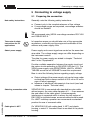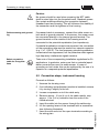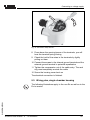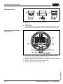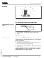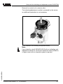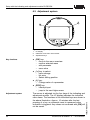
1
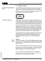
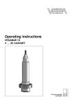
Operating Instructions
VEGAPULS 66 enamel
4 ... 20 mA/HART
Contents
Contents
1
About this document
1.1
1.2
1.3
2
.
.
.
.
.
.
.
.
.
.
.
.
.
.
.
.
.
.
.
.
.
.
.
.
.
.
.
.
.
.
.
.
.
.
.
.
.
.
.
.
.
.
.
.
.
.
.
.
.
.
.
.
.
.
.
.
.
.
.
.
.
.
.
.
.
.
.
.
..
..
..
..
11
12
13
13
General instructions. . . . . . . . . . . . . . . . . . . . . 15
Mounting instructions . . . . . . . . . . . . . . . . . . . . 16
Preparing the connection . . . . . . . . . . . . .
Connection steps, instrument housing. . . .
Wiring plan, single chamber housing. . . . .
Wiring plan, double chamber housing . . . .
Wiring plan, double chamber housing Exd.
Wiring plan, version IP 66/IP 68, 1 bar . . .
Switch-on phase . . . . . . . . . . . . . . . . . . .
.
.
.
.
.
.
.
.
.
.
.
.
.
.
..
..
..
..
..
..
..
23
24
25
27
29
31
31
Setup with the indicating and adjustment module
PLICSCOM
Short description . . . . . . . . . . . . . . . . . . . .
Insert the indicating and adjustment module
Adjustment system . . . . . . . . . . . . . . . . . .
Setup procedure . . . . . . . . . . . . . . . . . . . .
Menu schematic . . . . . . . . . . . . . . . . . . . .
.
.
.
.
.
..
..
..
..
..
32
32
34
35
42
VEGAPULS 66 enamel - 4 ... 20 mA/HART
31953-EN-070201
6.1
6.2
6.3
6.4
6.5
2
Configuration. . . . . . .
Principle of operation .
Operation . . . . . . . . .
Storage and transport
Connecting to voltage supply
5.1
5.2
5.3
5.4
5.5
5.6
5.7
6
6
6
6
6
7
7
8
8
9
9
Mounting
4.1
4.2
5
Authorised personnel . . . . . . . . . . . . . . . . . . . .
Appropriate use. . . . . . . . . . . . . . . . . . . . . . . .
Warning about misuse . . . . . . . . . . . . . . . . . . .
CE conformity . . . . . . . . . . . . . . . . . . . . . . . . .
Fulfilling NAMUR recommendations . . . . . . . . .
FCC and IC conformity (only for USA/Canada) .
Safety instructions for Ex areas . . . . . . . . . . . .
Manufacturer declaration . . . . . . . . . . . . . . . . .
Functional range of approved instruments . . . . .
Environmental instructions . . . . . . . . . . . . . . . .
Product description
3.1
3.2
3.3
3.4
4
5
5
5
For your safety
2.1
2.2
2.3
2.4
2.5
2.6
2.7
2.8
2.9
2.10
3
Function . . . . . . . . . . . . . . . . . . . . . . . . . . . . .
Target group . . . . . . . . . . . . . . . . . . . . . . . . . .
Symbolism used . . . . . . . . . . . . . . . . . . . . . . .
Contents
6.6
7
Setup with PACTware™ and other adjustment
programs
7.1
7.2
7.3
7.4
8
Connecting the PC . . . . . . . . . . . . . . . . . . .
Parameter adjustment with PACTware™. . . .
Parameter adjustment with AMS™ and PDM
Saving the parameter adjustment data . . . . .
..
..
..
..
45
46
47
47
..
..
..
..
48
48
50
50
Maintenance and fault rectification
8.1
8.2
8.3
8.4
9
Saving the parameter adjustment data . . . . . . . 44
Maintenance . . . . . . . . . . . . . . . . . .
Remove interferences . . . . . . . . . . .
Exchange of the electronics module .
Instrument repair . . . . . . . . . . . . . . .
.
.
.
.
.
.
.
.
.
.
.
.
.
.
.
.
.
.
.
.
.
.
.
.
Dismounting
9.1
9.2
Dismounting steps . . . . . . . . . . . . . . . . . . . . . . 52
Disposal . . . . . . . . . . . . . . . . . . . . . . . . . . . . . 52
10 Supplement
Technical data. . . . . . . .
Dimensions . . . . . . . . . .
Industrial property rights.
Trademark . . . . . . . . . .
.
.
.
.
.
.
.
.
.
.
.
.
.
.
.
.
.
.
.
.
.
.
.
.
.
.
.
.
.
.
.
.
.
.
.
.
.
.
.
.
.
.
.
.
.
.
.
.
.
.
.
.
.
.
.
.
.
.
.
.
..
..
..
..
53
61
63
63
31953-EN-070201
10.1
10.2
10.3
10.4
VEGAPULS 66 enamel - 4 ... 20 mA/HART
3
Contents
Supplementary operating instructions manuals
Information:
VEGAPULS 66 is available in many versions and is therefore
supplied according to customer order. Depending on the
selected version, supplementary operating instructions manuals also come with the delivery. You will find the supplementary operating instructions manuals in chapter "Product
description".
Operating instructions manuals for accessories and
replacement parts
Tip:
To ensure reliable setup and operation of your VEGAPULS 66,
we offer accessories and replacement parts. The associated
documents are:
l
l
4
VEGAPULS 66 enamel - 4 ... 20 mA/HART
31953-EN-070201
l
Operating instructions manual "External indicating and
adjustment unit VEGADIS 61"
Operating instructions manual "Oscillator VEGAPULS
series 60"
Supplementary instructions manual "Flanges according to
DIN-EN-ASME-JIS"
About this document
1 About this document
1.1 Function
This operating instructions manual has all the information you
need for quick setup and safe operation. Please read this
manual before you start setup.
1.2 Target group
This operating instructions manual is directed to trained,
qualified personnel. The contents of this manual should be
made available to these personnel and put into practice by
them.
1.3 Symbolism used
Information, tip, note
This symbol indicates helpful additional information.
Caution: If this warning is ignored, faults or
malfunctions can result.
Warning: If this warning is ignored, injury to persons and/or
serious damage to the instrument can result.
Danger: If this warning is ignored, serious injury to persons
and/or destruction of the instrument can result.
Ex applications
This symbol indicates special instructions for Ex applications.
List
The dot set in front indicates a list with no implied sequence.
à
Action
This arrow indicates a single action.
1
Sequence
Numbers set in front indicate successive steps in a procedure.
31953-EN-070201
l
VEGAPULS 66 enamel - 4 ... 20 mA/HART
5
For your safety
2 For your safety
2.1 Authorised personnel
All operations described in this operating instructions manual
must be carried out only by trained specialist personnel
authorised by the operator. For safety and warranty reasons,
any internal work on the instruments must be carried out only
by personnel authorised by the manufacturer.
2.2 Appropriate use
VEGAPULS 66 is a sensor for continuous level measurement.
Detailed information on the application range of VEGAPULS
66 is available in chapter "Product description".
2.3 Warning about misuse
Inappropriate or incorrect use of the instrument can give rise to
application-specific hazards, e.g. vessel overfill or damage to
system components through incorrect mounting or adjustment.
2.4 General safety instructions
VEGAPULS 66 is a high-tech instrument requiring the strict
observance of standard regulations and guidelines. The
emitting frequencies of all radar sensors are in the C or K-band
range (depending on the instrument version). The low transmitting power is far below the internationally permitted limit
values, and when the instrument is used correctly, no healthendangering effects are to be expected. There are no
restrictions on using the instrument on the outside of metallic,
closed vessels.The user must take note of the safety
instructions in this operating instructions manual, the countryspecific installation standards (e.g. the VDE regulations in
Germany) as well as all prevailing safety regulations and
accident prevention rules.
2.5 CE conformity
Conformity has been judged according to the following
standards:
l
6
EMC: EN 61326: 2004
VEGAPULS 66 enamel - 4 ... 20 mA/HART
31953-EN-070201
VEGAPULS 66 is in CE conformity with EMVG (89/336/EWG),
R & TTE directive (1999/5/EC) and LVD (73/23/EWG).
For your safety
-
-
Emission: Class B
Susceptibility: Industrial areas
l
R & TTE directive: I-ETS 300-440 Expert opinion No.
0043052-01/SEE, Notified Body No. 0499
l
LVD: EN 61010-1: 2002
2.6 Fulfilling NAMUR recommendations
With regard to interference resistance and interference
emission, VEGAPULS 66 fulfils NAMUR recommendation
NE 21.
VEGAPULS 66 and its indicating and adjustment components
fulfill NAMUR recommendation NE 53 in respect to compatibility. VEGA instruments are generally upward and downward
compatible:
l
l
l
Sensor software to DTM VEGAPULS 66 HART, PA or FF
DTM VEGAPULS 66 for adjustment software PACTware™
Indicating and adjustment module for sensor software
The parameter adjustment of the basic sensor functions is
independent of the software version. The range of available
functions depends on the respective software version of the
individual components.
The software version of VEGAPULS 66 can be determined as
follows:
l
l
l
via PACTware™
on the type label of the electronics
via the indicating and adjustment module
You can view all software histories on our website www.vega.
com. Make use of this advantage and get registered for update
information via e-mail.
2.7 FCC and IC conformity (only for USA/Canada)
VEGAPULS 66 is FCC and IC approved:
l
31953-EN-070201
l
FCC ID: O6QPULS6566
IC: 3892A-PS6566
Modifications not expressly approved by VEGA will lead to
expiry of the operating licence according to FCC.
VEGAPULS 66 is in conformity with part 15 of the FCC
regulations. Take note of the respective operating regulations:
l
The instrument must not cause any interfering emissions
VEGAPULS 66 enamel - 4 ... 20 mA/HART
7
For your safety
l
The instrument must be insensitive to interfering emissions, also to such that may cause unwanted operating
conditions.
VEGAPULS 66 was tested and meets the limit values for a
digital instrument of class B, according to part 15 of the FCC
regulations. The limit values are for protection against
interfering emissions during operation in industrial environment.
The instrument can generate, use and emit high frequency
energy and can generate interfering emissions if not used as
described in the operator's manual. Because interfering
emissions have to be reckoned with when the instrument is
used in residential areas, the user must make sure necessary
countermeasures are implemented.
2.8 Safety instructions for Ex areas
Please note the Ex-specific safety information for installation
and operation in Ex areas. These safety instructions are part of
the operating instructions manual and come with the Exapproved instruments.
2.9 Manufacturer declaration
In conformity with DIN EN 60079-14/2004, para. 5.2.3, point
c1, VEGAPULS 66 is suitable for use in zone 2.
The operator must use the instrument as it was intended to be
used and follow the specifications of the following documents:
l
l
l
this operating instructions manual
this manufacturer declaration (24626)
the applicable installation regulations
Max. increase of the surface temperature during operation:
27 K (individual components in the instrument)
With an ambient temperature of 70 °C (158 °F) on the housing
and a process temperature of 70 °C (158 °F), the max. ambient
temperature during operation is 97 °C (207 °F).
Measures to maintain explosion protection during operation:
l
VEGAPULS 66 enamel - 4 ... 20 mA/HART
31953-EN-070201
8
Operate the instrument in the range of the specified
electrical limit values. Permissible supply voltage: see
"Technical data"
For your safety
l
l
l
l
l
l
l
Mount and operate the instrument in such a way that no
danger of ignition from electrostatic charges is to be
expected. The antenna, the process fitting or the housing
(as the case may be depending on instrument version) are
made of electrically non-conductive plastic.
Make sure that the seal is mounted correctly between
lower part of the housing and cover. Screw the cover on
tightly.
Make sure there is no explosive atmosphere present if you
intend to operate the instrument with opened cover
Make sure that the cable gland is tight and strain-relieved.
The outer diameter of the connection cable must be
adapted to the cable gland. Tighten the pressure screw of
the cable gland carefully.
Cover unused openings for cable glands tightly
Mount the instrument in such a way that the sensor cannot
touch the vessel wall or vessel installations. Keep in mind
the influence of product movement in the vessel.
The surface temperature of the housing must not exceed
the ignition temperature of the surrounding explosive
atmosphere
This instrument was assessed by a person who fulfils the DIN
EN 60079-14 requirements.
2.10 Functional range of approved instruments
Instruments with national approvals such as according to FM
or CSA are partly supplied with a previous hardware or
software version. For approval-technical reasons, some
functions for these instruments will be only available at a later
date.
You will find corresponding instructions in the description of
the individual functions in this operating instructions manual.
31953-EN-070201
2.11 Environmental instructions
Protection of the environment is one of our most important
duties. That is why we have introduced an environment
management system with the goal of continuously improving
company environmental protection. The environment management system is certified according to DIN EN ISO 14001.
Please help us fulfil this obligation by observing the environmental instructions in this manual:
l
Chapter "Storage and transport"
VEGAPULS 66 enamel - 4 ... 20 mA/HART
9
For your safety
l
Chapter "Disposal"
31953-EN-070201
10
VEGAPULS 66 enamel - 4 ... 20 mA/HART
Product description
3 Product description
3.1 Configuration
Scope of delivery
The scope of delivery encompasses:
l
l
Components
VEGAPULS 66 radar sensor
Documentation
- this operating instructions manual
- Supplementary instructions manual "Safety Manual
according to IEC 61508/IEC 61511 (SIL)"
- Operating instructions manual "Indicating and adjustment module" (optional)
- Supplementary instructions manual "Heating for indicating and adjustment module" (optional)
- Supplementary instructions manual "Plug connector for
continuously measuring sensors" (optional)
- Ex-specific "Safety instructions" (with Ex-versions)
- if necessary, further certificates
VEGAPULS 66 consists of the following components:
l
l
l
Process fitting with enamelled antenna system
Housing with electronics, optionally available with plug
connector, optionally available with connection cable
Housing cover, optionally available with indicating and
adjustment module PLICSCOM
31953-EN-070201
The components are available in different versions.
VEGAPULS 66 enamel - 4 ... 20 mA/HART
11
Product description
1
2
3
Fig.
1
2
3
1: VEGAPULS 66 in enamel version with plastic housing
Housing cover with integrated PLICSCOM (optional)
Housing with electronics
Process fitting with antenna system
3.2 Principle of operation
Area of application
VEGAPULS 66 is a radar sensor in C-band technology for
continuous level measurement.
The version with enamelled antenna is particularly suitable
for measurement of highly corrosive liquids, preferably in
enamelled vessels under difficult process conditions such as
buildup, condensation and foam generation as well as strong
product movement.
12
The antenna of the radar sensor emits short radar pulses with
a duration of approx. 1 ns. These pulses are reflected by the
product and received by the antenna as echoes. The running
time of the radar pulses from emission to reception is
VEGAPULS 66 enamel - 4 ... 20 mA/HART
31953-EN-070201
Functional principle
Product description
proportional to the distance and hence to the level. The
determined level is converted into an appropriate output signal
and outputted as measured value.
Supply
Two-wire electronics 4 … 20 mA/HART for power supply and
measured value transmission over the same cable.
The supply voltage range can differ depending on the
instrument version.
The data for power supply are stated in chapter "Technical
data" in the "Supplement".
The backlight of the indicating and adjustment module is
powered by the sensor. The prerequisite for this is a supply
voltage at a certain level. The exact voltage specifications are
stated in chapter "Technical data" in the "Supplement".
For instruments with national approvals such as e.g. according
to FM and CSA, this function only available at a later date.
The optional heating requires its own power supply. You can
find further details in the supplementary instructions manual
"Heating for indicating and adjustment module".
This function is generally not available for approved instruments.
3.3 Operation
VEGAPULS 66 can be adjusted with different adjustment
media:
l
l
l
l
with indicating and adjustment module
with the suitable VEGA DTM in conjunction with an
adjustment software according to the FDT/DTM standard,
e.g. PACTware™ and PC
with manufacturer-specific adjustment programs AMS™ or
PDM
a HART handheld
31953-EN-070201
The entered parameters are generally saved in VEGAPULS
66, optionally also in the indicating and adjustment module or
in PACTware™.
3.4 Storage and transport
Packaging
Your instrument was protected by packaging during transport.
Its capacity to handle normal loads during transport is assured
by a test according to DIN EN 24180.
VEGAPULS 66 enamel - 4 ... 20 mA/HART
13
Product description
The packaging of standard instruments consists of environment-friendly, recyclable cardboard. For special versions, PE
foam or PE foil is also used. Dispose of the packaging material
via specialised recycling companies.
Storage and transport temperature
l
l
Storage and transport temperature see "Supplement Technical data - Ambient conditions"
Relative humidity 20 … 85 %
31953-EN-070201
14
VEGAPULS 66 enamel - 4 ... 20 mA/HART
Mounting
4 Mounting
4.1 General instructions
Installation position
Select an installation position you can easily reach for
mounting and connecting as well as later retrofitting of an
indicating and adjustment module. The housing can be rotated
by 330° without the use of any tools. You can also install the
indicating and adjustment module in four different positions
(each displaced by 90°).
Moisture
Use the recommended cables (see chapter "Connecting to
power supply") and tighten the cable gland.
You can give your VEGAPULS 66 additional protection against
moisture penetration by leading the connection cable downward in front of the cable entry. Rain and condensation water
can thus drain off. This applies mainly to mounting outdoors, in
areas where moisture is expected (e.g. by cleaning processes)
or on cooled or heated vessels.
Fig. 2: Measures against moisture penetration
The reference plane for the measuring range is the lower edge
of the flange.
31953-EN-070201
Measuring range
VEGAPULS 66 enamel - 4 ... 20 mA/HART
15
Mounting
1
2
3
4
100%
0%
Fig.
1
2
3
4
3: Measuring range (operating range) and max. measuring distance
full
empty (max. measuring distance)
Measuring range
Reference plane
Information:
If the medium reaches the antenna, buildup can form on it and
cause faulty measurements later on.
Materials, wetted parts
Make sure that the wetted parts of VEGAPULS 66, especially
the seal and process fitting, are suitable for the existing
process conditions such as pressure, temperature etc. as well
as the chemical properties of the medium.
You will find specification in chapter "Technical data" in the
"Supplement".
Enamel coating
Instruments with enamel coating should be treated very
carefully and shocks should be avoided. Unpack VEGAPULS
66 directly before installation. Insert VEGAPULS 66 carefully
into the vessel opening and avoid touching any sharp vessel
parts.
4.2 Mounting instructions
Installation position
VEGAPULS 66 enamel - 4 ... 20 mA/HART
31953-EN-070201
16
Mount VEGAPULS 66 at least 500 mm (19.685 in) from the
vessel wall. If the sensor is installed in the center of vessels
with dished or round tops, multiple echoes can arise. These
can, however, be suppressed by an appropriate adjustment
(see "Setup").
Mounting
If this distance cannot be maintained, a false echo storage
should be carried out during setup. This applies particularly if
buildup on the vessel wall is expected. In such case, we
recommend repeating the false echo storage later on with
existing buildup.
1
2
> 500 mm
Fig. 4: Mounting on round vessel tops
1 Reference plane
2 Vessel center or symmetry axis
31953-EN-070201
In vessels with conical bottom it can be advantageous to
mount the sensor in the center of the vessel, as measurement
is then possible down to the lowest point of the vessel bottom.
Fig. 5: Vessel with conical bottom
VEGAPULS 66 enamel - 4 ... 20 mA/HART
17
Mounting
Inflowing medium
Do not mount the instruments in or above the filling stream.
Make sure that you detect the product surface and not the
inflowing product.
Fig. 6: Inflowing liquid
Socket pieces should be dimensioned such that the antenna
end protrudes at least 10 mm (0.4 in) out of the socket.
ca. 10 mm
Socket
Fig. 7: Recommended socket mounting
Sensor orientation
In liquids, direct the sensor as perpendicular as possible to the
product surface to achieve an optimum measurement.
31953-EN-070201
18
VEGAPULS 66 enamel - 4 ... 20 mA/HART
Mounting
Fig. 8: Orientation in liquids
Vessel installations
The mounting location of the radar sensor should be a place
where no other equipment or fixtures cross the path of the
microwave signals.
Vessel installations such as, for example, ladders, limit
switches, heating spirals, struts, etc. can cause false echoes
that get superimposed on the useful echo. Make sure when
planning your measuring site that the radar sensor has a "clear
view" to the measured product.
If there are existing vessel installations, a false echo storage
should be carried out during setup.
If large vessel installations such as struts or supports cause
false echoes, these can be attenuated through supplementary
measures. Small, inclined sheet metal baffles above the
installations scatter the radar signals and prevent direct
interfering reflections.
Fig. 9: Cover smooth profiles with deflectors
If there are agitators in the vessel, a false echo storage should
be carried out with the agitators in motion. This ensures that
the interfering reflections from the agitators are saved with the
blades in different positions.
31953-EN-070201
Agitators
VEGAPULS 66 enamel - 4 ... 20 mA/HART
19
Mounting
Fig. 10: Agitators
Foam generation
Through the action of filling, stirring and other processes in the
vessel, dense foams which considerably damp the emitted
signals may form on the product surface.
If foams are causing measurement errors, the biggest possible
radar antenna should be used.
VEGAFLEX sensors with guided microwaves are not influenced by foam generation and are particularly suitable for such
applications.
Measurement in the standpipe (surge or bypass tube)
By using a standpipe, the influence of vessel installations and
turbulence can be excluded. Under these prerequisites, the
measurement of products with low dielectric values (from DK
value 1.6) is possible.
Surge or bypass tubes must extend all the way down to the
requested min. level, as measurement is only possible within
the tube.
Surge pipe
Make sure you provide the necessary upper vent hole in the
surge pipe. The hole must be aligned so that it and the
polarisation marking on the sensor flange are in the same
plane (see illustration: "Pipe antenna system in a tank").
31953-EN-070201
20
VEGAPULS 66 enamel - 4 ... 20 mA/HART
Mounting
1
max.
2
min.
Fig. 11: Pipe antenna system in a tank. The vent hole in the surge pipe must be
in one plane with the polarisation marking on the sensor.
1 Marking of the polarisation direction
2 Vent holde max. ø 5 mm (0.2 in)
If possible, the diameter of the sensor antenna should
correspond to the inner diameter of the tube. With VEGAPULS
66 this is approx. 50 mm (1.969 in) depending on the antenna.
The sensor can be used with tube diameters between
50 … 250 mm (1.969 … 9.843 in).
Bypass tube
As an alternative to the surge pipe in the vessel, a pipe system
can be mounted outside of the vessel as a bypass tube. For
setup, select the function "Bypass tube".
31953-EN-070201
Align the sensor in such a way that the polarisation marking on
the sensor flange is in the same plane as the tube holes or the
tube connection openings (see illustration: "VEGAPULS in a
bypass tube").
VEGAPULS 66 enamel - 4 ... 20 mA/HART
21
Mounting
100%
> 500 mm
1
0%
Fig. 12: VEGAPULS 66 in a bypass tube. The polarisation marking on the
process fitting must be in one plane to the tube holes or the tube connection
openings.
1 Marking of the polarisation direction
When the sensor is mounted on a bypass tube, the distance
from VEGAPULS 66 to the upper tube connection should be
approx. 500 mm (19.685 in) or more. In case of extremely
rough tube inner walls, you should use an inserted tube (tube
in tube) or a radar sensor with tube antenna.
Information:
With VEGAPULS 66 in flange version, the polarisation plane
always lies in centre between two flange holes.
31953-EN-070201
22
VEGAPULS 66 enamel - 4 ... 20 mA/HART
Connecting to voltage supply
5 Connecting to voltage supply
5.1 Preparing the connection
Note safety instructions
Generally note the following safety instructions:
l
l
Connect only in the complete absence of line voltage
If overvoltage surges are expected, overvoltage arresters
should be installed
Tip:
We recommend using VEGA overvoltage arresters ÜS-F-LB-I
and ÜSB 62-36G.X.
Take note of safety
instructions for Ex
applications
In hazardous areas you should take note of the appropriate
regulations, conformity and type approval certificates of the
sensors and power supply units.
Select power supply
Power supply and current signal are carried on the same twowire cable. The voltage supply range can differ depending on
the instrument version.
The data for power supply are stated in chapter "Technical
data" in the "Supplement".
Provide a reliable separation between the supply circuit and
the mains circuits according to DIN VDE 0106 part 101. The
VEGA power supply units VEGATRENN 149A Ex, VEGASTAB 690 as well as all VEGAMETs meet this requirement.
Bear in mind the following factors regarding supply voltage:
l
31953-EN-070201
l
Output voltage of the power supply unit can be lower under
nominal load (with a sensor current of 20.5 mA or 22 mA in
case of failure message)
Influence of additional instruments in the circuit (see load
values in chapter "Technical data")
Selecting connection cable
VEGAPULS 66 is connected with standard two-wire cable
without screen. An outer cable diameter of 5 … 9 mm ensures
the seal effect of the cable gland. If electromagnetic
interference is expected which is above the test values of
EN 61326 for industrial areas, screened cable should be used.
For HART multidrop operation we recommend as standard
practice the use of screened cable.
Cable gland ½ NPT
On VEGAPULS 66 with cable gland ½ NPT and plastic
housing, a metal ½" threaded insert is moulded in the plastic
housing.
VEGAPULS 66 enamel - 4 ... 20 mA/HART
23
Connecting to voltage supply
Caution:
No grease should be used when screwing the NPT cable
gland or steel tube into the threaded insert. Standard grease
can contain additives affecting the connection between
threaded insert and housing. This will influence the stability of
the connection and the tightness of the housing.
Cable screening and grounding
If screened cable is necessary, connect the cable screen on
both ends to ground potential. In the sensor, the screen must
be connected directly to the internal ground terminal. The
ground terminal on the outside of the housing must be
connected to the potential equalisation (low impedance).
If potential equalisation currents are expected, the connection
on the processing side must be made via a ceramic capacitor
(e.g. 1 nF, 1500 V). The low frequency potential equalisation
currents are thus suppressed, but the protective effect against
high frequency interference signals remains.
Select connection
cable for Ex applications
Take note of the corresponding installation regulations for Ex
applications. In particular, make sure that no potential equalisation currents flow over the cable screen. In case of
grounding on both sides this can be achieved by the use of a
capacitor or a separate potential equalisation.
5.2 Connection steps, instrument housing
Proceed as follows:
Unscrew the housing cover
2
If an indicating and adjustment module is installed, remove
it by turning it slightly to the left.
3
Loosen compression nut of the cable entry
4
Remove approx. 10 cm (4 in) of the cable mantle, strip
approx. 1 cm (0.4 in) insulation from the ends of the
individual wires
5
Insert the cable into the sensor through the cable entry
6
Lift the opening levers of the terminals with a screwdriver
(see following illustration)
7
Insert the wire ends into the open terminals according to
the wiring plan
VEGAPULS 66 enamel - 4 ... 20 mA/HART
31953-EN-070201
24
1
Connecting to voltage supply
Fig. 13: Connection steps 6 and 7
8
Press down the opening levers of the terminals, you will
hear the terminal spring closing
9
Check the hold of the wires in the terminals by lightly
pulling on them
10 Connect the screen to the internal ground terminal and the
external ground terminal to potential equalisation
11 Tighten the compression nut of the cable entry. The seal
ring must completely encircle the cable
12 Screw the housing cover back on
The electrical connection is finished.
5.3 Wiring plan, single chamber housing
31953-EN-070201
The following illustrations apply to the non-Ex as well as to the
Ex ia version.
VEGAPULS 66 enamel - 4 ... 20 mA/HART
25
Connecting to voltage supply
Housing overview
4
4
1
Fig.
1
2
3
4
4
2
3
14: Material versions, single chamber housing
Plastic
Aluminium
Stainless steel
Filter element for air pressure compensation of all material versions. Blind
stopper with version IP 66/IP 68, 1 bar for Aluminium and stainless steel
Electronics and connection
compartment
Display
I2C
4
1
2
5 6 7 8
1
2
3
Fig. 15: Electronics and connection compartment, single chamber housing
1 Plug connector for VEGACONNECT (I²C interface)
2 Spring-loaded terminals for connection of the external indication VEGADIS
61
3 Ground terminal for connection of the cable screen
4 Spring-loaded terminals for voltage supply
31953-EN-070201
26
VEGAPULS 66 enamel - 4 ... 20 mA/HART
Connecting to voltage supply
Wiring plan
Display
I2C
1
2
5
6
7
8
1
Fig. 16: Wiring plan, single chamber housing
1 Power supply/Signal output
5.4 Wiring plan, double chamber housing
The following illustration apply to non-Ex as well as Ex ia
versions. The Exd version is described in the next subchapter.
Housing overview
1
2
3
4
Fig.
1
2
3
4
31953-EN-070201
5
1)
1)
5
17: Double chamber housing
Housing cover, connection compartment
Blind stopper or plug M12x1 for VEGADIS 61 (option)
Housing cover, electronics compartment
Filter element for pressure compensation or blind stopper with version IP 66/
IP 68, 1 bar1)
Cable entry or plug
Version IP 66/IP 68, 1 bar not with four-wire instruments
VEGAPULS 66 enamel - 4 ... 20 mA/HART
27
Connecting to voltage supply
Electronics compartment
1
Display
I2C
1
2
5 6 7 8
2
3
Fig.
1
2
3
18: Electronics compartment, double chamber housing
Plug connector for VEGACONNECT (I²C interface)
Internal connection cable to the connection compartment
Terminals for VEGADIS 61
Display
Connection compartment
1
3
1
2
I²C
2
Fig.
1
2
3
19: Connection compartment, double chamber housing
Plug connector for VEGACONNECT (I²C interface)
Ground terminal for connection of the cable screen
Spring-loaded terminals for voltage supply
31953-EN-070201
28
VEGAPULS 66 enamel - 4 ... 20 mA/HART
Connecting to voltage supply
Wiring plan
I2C
1
2
1
Fig. 20: Wiring plan, double chamber housing
1 Power supply/Signal output
5.5 Wiring plan, double chamber housing Exd
Housing overview
1
2
3
4
Fig.
1
2
3
4
31953-EN-070201
5
2)
2)
5
21: Double chamber housing
Housing cover, connection compartment
Blind stopper or plug M12x1 for VEGADIS 61 (option)
Housing cover, electronics compartment
Filter element for pressure compensation or blind stopper with version IP 66/
IP 68, 1 bar2)
Cable entry or plug
Version IP 66/IP 68, 1 bar not with four-wire instruments
VEGAPULS 66 enamel - 4 ... 20 mA/HART
29
Connecting to voltage supply
Electronics compartment
1
Display
I2C
1
2
5 6 7 8
2
3
Fig.
1
2
3
22: Electronics compartment, double chamber housing
Plug connector for VEGACONNECT (I²C interface)
Internal connection cable to the connection compartment
Terminals for VEGADIS 61
Connection compartment
1
1 2
2
Fig. 23: Connection compartment, double chamber housing Exd
1 Spring-loaded terminals for power supply and cable screen
2 Ground terminal for connection of the cable screen
31953-EN-070201
30
VEGAPULS 66 enamel - 4 ... 20 mA/HART
Connecting to voltage supply
Wiring plan
1
2
1
Fig. 24: Wiring plan, double chamber housing Exd
1 Power supply/Signal output
5.6 Wiring plan, version IP 66/IP 68, 1 bar
Wire assignment, connection
cable
+
1
2
Fig. 25: Wire assignment, connection cable
1 brown (+) and blue (-) to power supply or to the processing system
2 Screen
5.7 Switch-on phase
Switch-on phase
After connecting VEGAPULS 66 to power supply or after a
voltage recurrence, the instrument carries out a self-check for
approx. 30 seconds:
l
l
31953-EN-070201
l
Internal check of the electronics
Indication of the instrument type, the firmware as well as
the sensor TAGs (sensor designation)
Output signal jumps briefly (approx. 10 seconds) to the set
fault current
Then the corresponding current is outputted to the cable (the
value corresponds to the actual level as well as the settings
already carried out, e.g. factory setting).
VEGAPULS 66 enamel - 4 ... 20 mA/HART
31
Setup with the indicating and adjustment module PLICSCOM
6 Setup with the indicating and
adjustment module PLICSCOM
6.1 Short description
Function/Configuration
The indicating and adjustment module is used for measured
value display, adjustment and diagnosis. It can be mounted in
the following housing versions and instruments:
l
l
All sensors of the plics® instrument family, in the single as
well as in the double chamber housing (optionally in the
electronics or connection compartment)
External indicating and adjustment unit VEGADIS 61
From a hardware revision …- 01 or higher of the indicating and
adjustment module as well as of the corresponding sensor, an
integrated backlight can be switched on via the adjustment
menu. The hardware revision is stated on the type label of the
indicating and adjustment module or the sensor electronics.
Information:
For instruments with national approvals such as e.g. according
to FM and CSA, this function only available at a later date.
Note:
You will find detailed information on the adjustment in the
operating instructions manual of the "Indicating and adjustment
module".
6.2 Insert the indicating and adjustment module
Mounting/dismounting the indicating and adjustment
module
The indicating and adjustment module can be inserted into the
sensor and removed again at any time. It is not necessary to
interrupt the power supply.
Proceed as follows:
Unscrew the housing cover
2
Place the indicating and adjustment module in the desired
position on the electronics (you can choose any one of four
different positions - each displaced by 90°)
3
Press the indicating and adjustment module onto the
electronics and turn it to the right until it snaps in.
4
Screw housing cover with inspection window tightly back
on
VEGAPULS 66 enamel - 4 ... 20 mA/HART
31953-EN-070201
32
1
Setup with the indicating and adjustment module PLICSCOM
Removal is carried out in reverse order.
The indicating/adjustment module is powered by the sensor,
an additional connection is not necessary.
Fig. 26: Installation of the indicating and adjustment module
31953-EN-070201
Note:
If you intend to retrofit VEGAPULS 66 with an indicating and
adjustment module for continuous measured value indication,
a higher cover with an inspection glass is required.
VEGAPULS 66 enamel - 4 ... 20 mA/HART
33
Setup with the indicating and adjustment module PLICSCOM
6.3 Adjustment system
2
1
1.1
3
Key functions
Adjustment system
27: Indicating and adjustment elements
LC display
Indication of the menu item number
Adjustment keys
l
[OK] key:
- move to the menu overview
- confirm selected menu
- edit parameter
- save value
l
[->] key to select:
- menu change
- list entry
- Select editing position
l
[+] key:
- Change value of a parameter
l
[ESC] key:
- interrupt input
- jump to the next higher menu
The sensor is adjusted via the four keys of the indicating and
adjustment module. The LC display indicates the individual
menu items. The functions of the individual keys are shown in
the above illustration. Approx. 10 minutes after the last
pressing of a key, an automatic reset to measured value
indication is triggered. Any values not confirmed with [OK] will
not be saved.
VEGAPULS 66 enamel - 4 ... 20 mA/HART
31953-EN-070201
34
Fig.
1
2
3
Setup with the indicating and adjustment module PLICSCOM
6.4 Setup procedure
Address setting HART-Multidrop
In HART-Multidrop mode (several sensors on one input) the
address must be set before continuing with the parameter
adjustment. You will find a detailed description in the operating
instructions manual "Indicating and adjustment module" or in
the online help of PACTware™ or DTM.
HART mode
Standard
Address 0
Parameter adjustment
As VEGAPULS 66 is a distance measuring instrument, the
distance from the sensor to the product surface is measured.
To have the real product level displayed, an allocation of the
measured distance to the percentage height must be made. To
carry out this adjustment, the distance is entered with full and
empty vessel. If these values are not known, an adjustment
with the distance values, e.g. 10 % and 90 % is also possible.
Starting point for these distance specifications is always the
seal surface of the thread or flange. With these settings, the
real level is calculated. Furthermore the operating range of the
sensor is limited from maximum to the required range.
The real product level during this adjustment is not important,
because the min./max. adjustment is always carried out
without changing the product level. These settings can be
made ahead of time without the instrument having to be
installed.
Caution:
If there is a separation of liquids with different dielectric values
in the vessel, e.g. by condensation, VEGAPULS 66 can detect
under certain circumstances only the medium with the higher
dielectric value.
Keep in mind that interfaces can cause faulty measurements.
31953-EN-070201
If you want to measure the total height of both liquids reliably,
please contact our service department or use an instrument
specially designed for interface measurement.
In the main menu item "Basic adjustment", the individual
submenu items should be selected one after the other and
provided with the correct parameter values.
VEGAPULS 66 enamel - 4 ... 20 mA/HART
35
Setup with the indicating and adjustment module PLICSCOM
Start your parameter adjustment with the following menu items
of the basic adjustment:
Carrying out min. adjustment
Proceed as follows:
1
▶
2
Move from the measured value display to the main menu
by pushing [OK].
Basic adjustment
Indication
Diagnostics
Service
Info
Select the menu item "Basic adjustment" with [->] and
confirm with [OK]. Now the menu item "Min. adjustment" is
displayed.
Min. adjustment
0.00 %
=
5,000 m(d)
4,000 m(d)
Carrying out max. adjustment
3
Prepare the % value for editing with [OK] and set the
cursor to the requested position with [->]. Set the
requested percentage value with [+] and save with [OK].
The cursor jumps now to the distance value.
4
Enter the appropriate distance value in m (corresponding
to the percentage value) for the empty vessel (e.g. distance
from the sensor to the vessel bottom).
5
Save the settings with [OK] and move to "Max. adjustment"
with [->].
Proceed as follows:
Min. adjustment
100.00 %
=
1,000 m(d)
2,000 m(d)
Prepare the % value for editing with [OK] and set the
cursor to the requested position with [->]. Set the
requested percentage value with [+] and save with [OK].
The cursor jumps now to the distance value.
2
Enter the appropriate distance value in m (corresponding
to the percentage value) for the full vessel. Keep in mind
that the max. level must lie below the dead band.
3
Save the settings with [OK] and move to "Medium
selection" with [->].
VEGAPULS 66 enamel - 4 ... 20 mA/HART
31953-EN-070201
36
1
Setup with the indicating and adjustment module PLICSCOM
Medium selection
Each product has different reflective properties. In addition,
there are various interfering factors which have to be taken into
account: agitated product surfaces and foam generation (with
liquids); dust generation, material cones and echoes from the
vessel wall (with solids). To adapt the sensor to these different
conditions, you should first select "Liquid" or "Solid".
Medium
Liquid
According to the conductivity and the dielectric value of liquids,
the reflection properties can differ considerably. Therefore
additional options such as "Solvent", "Chem. mixture" and
"Water based" are offered below the menu item Liquid.
With solids, you can also choose between "Powder/Dust",
"Granular/Pellets" or "Ballast/Pebbels".
Through this additional selection, the sensor is adapted
perfectly to the product and measurement reliability, particularly in products with bad reflective properties, is considerably
increased.
Enter the requested parameter via the appropriate keys, save
your settings and jump to the next menu item with the [->] key.
Vessel form
Apart from the medium, the vessel shape can also influence
the measurement. To adapt the sensor to these measuring
conditions, this menu item offers different options depending
on whether liquid or solid is selected. With "Liquid" these are
"Storage tank", "Stilling tube", "Open vessel" or "Stirred
vessel", with "Solid", "Silo" or "Bunker".
Vessel form
Storage tank
Enter the requested parameter via the appropriate keys, save
your settings and jump to the next menu item with the [->] key.
31953-EN-070201
Linearisation curve
A linearization is necessary for all vessels in which the vessel
volume does not increase linearly with the level - e.g. with a
cylindrical or spherical tank - and the indication or output of the
volume is required. Corresponding linearization curves are
preprogrammed for these vessels. They represent the
correlation between the level percentage and vessel volume.
VEGAPULS 66 enamel - 4 ... 20 mA/HART
37
Setup with the indicating and adjustment module PLICSCOM
By activating the appropriate curve, the volume percentage of
the vessel is displayed correctly. If the volume should not be
displayed in percent but e.g. in l or kg, a scaling can be also
set in the menu item "Display".
Linearisation curve
linear
Enter the requested parameter via the appropriate keys, save
your settings and jump to the next menu item with the [->] key.
Caution:
Note the following, if VEGAPULS 66 is used as part of an
overfill protection system according to WHG:
If a linearisation curve is selected, the measuring signal is no
longer compulsorily linear proportional to the level. This must
be taken into consideration by the user, particularly when
adjusting the switching point on the level switch.
Gating out of false signals
High sockets or vessel installations, such as e.g. struts or
agitators as well as buildup and weld joints on the vessel walls
cause interfering reflections which can impair the measurement. A false echo storage detects and marks these false
echoes, so that they are no longer taken into account for the
level measurement. A false echo memory should be created
with empty vessel so that all potential interfering reflections will
be detected.
Gating out of false signals
Change now?
Proceed as follows:
1
Move from the measured value display to the main menu
by pushing [OK].
2
Select the menu item "Service" with [->] and confirm with
[OK]. Now the menu item "False signal suppression" is
displayed.
31953-EN-070201
38
VEGAPULS 66 enamel - 4 ... 20 mA/HART
Setup with the indicating and adjustment module PLICSCOM
3
Confirm "False signal suppression - Change now" with
[OK] and select in the below menu "Create new". Enter the
actual distance from the sensor to the product surface. All
false signals in this area are detected by the sensor and
saved after confirming with [OK].
Note:
Check the distance to the product surface, because if an
incorrect (too large) value is entered, the existing level will be
saved as false signal. The filling level would then no longer be
detectable in this area.
The menu item "Extended setting" offers the possibility to
optimise VEGAPULS 66 for applications in which the level
changes very quickly. For this reason, select the function
"Quick level change >1m/min.".
Extended setting
None
Note:
Because the average value generation of the signal processing is clearly reduced with the function "Quick level change
>1m/min.", false reflections caused by agitators or vessel
installations can cause measured value fluctuations. A false
echo storage is recommended.
This function enables reading out parameter adjustment data
as well as writing parameter adjustment data into the sensor
via the indicating and adjustment module. A description of the
function is available in the operating instructions manual
"Indicating and adjustment module".
The following data are read out or written with this function:
l
l
l
l
31953-EN-070201
l
l
l
l
l
l
Measured value presentation
Adjustment
Medium
Inner diameter of the standpipe (with standpipe versions)
Vessel form
Damping
Linearisation curve
Sensor-TAG
Displayed value
Display unit
VEGAPULS 66 enamel - 4 ... 20 mA/HART
39
VEGA Grieshaber KG
Am Hohenstein 113
77761 Schiltach
Germany
Phone +49 7836 50-0
Fax +49 7836 50-201
E-mail: [email protected]
www.vega.com
ISO 9001
All statements concerning scope of delivery, application,
practical use and operating conditions of the sensors and
processing systems correspond to the information available at the time of printing.
© VEGA Grieshaber KG, Schiltach/Germany 2007
Subject to change without prior notice
31953-EN-070201