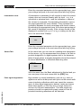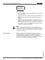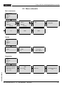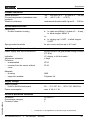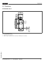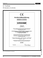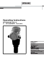
1
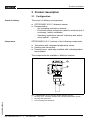
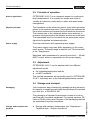
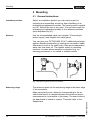
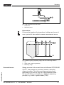
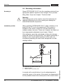
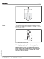
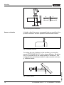
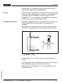
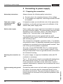
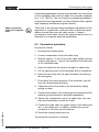
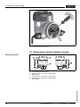
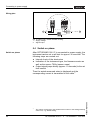
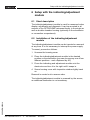
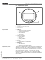
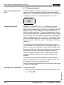
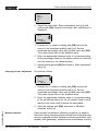
Operating Instructions
OPTISOUND 3010 C
4 ... 20 mA/HART - four-wire
Contents
Contents
1
About this document
1.1
1.2
1.3
2
.
.
.
.
.
.
.
.
.
.
.
.
.
.
.
.
.
.
.
.
.
..
..
..
..
..
..
..
6
6
6
6
6
6
7
Configuration. . . . . . .
Principle of operation .
Adjustment . . . . . . . .
Storage and transport
.
.
.
.
.
.
.
.
.
.
.
.
.
.
.
.
.
.
.
.
.
.
.
.
.
.
.
.
.
.
.
.
.
.
.
.
.
.
.
.
.
.
.
.
.
.
.
.
.
.
.
.
.
.
.
.
.
.
.
.
.
.
.
.
.
.
.
.
..
..
..
..
8
9
9
9
General instructions. . . . . . . . . . . . . . . . . . . . . 11
Mounting information . . . . . . . . . . . . . . . . . . . . 13
..
..
..
..
19
20
21
23
Short description . . . . . . . . . . . . . . . . . . . . . . .
Installation of the indicating/adjustment module .
Adjustment system . . . . . . . . . . . . . . . . . . . . .
Setup procedure . . . . . . . . . . . . . . . . . . . . . . .
Menu schematic . . . . . . . . . . . . . . . . . . . . . . .
24
24
26
27
31
Preparing the connection . . . . . . . . . .
Connection procedure . . . . . . . . . . . .
Wiring plans, double chamber housing
Switch on phase . . . . . . . . . . . . . . . .
.
.
.
.
.
.
.
.
.
.
.
.
.
.
.
.
.
.
.
.
Maintenance and fault rectification
Maintenance . . . . . . . . . . .
Fault rectification . . . . . . . .
Exchanging the electronics.
Instrument repair . . . . . . . .
.
.
.
.
.
.
.
.
.
.
.
.
.
.
.
.
.
.
.
.
.
.
.
.
.
.
.
.
.
.
.
.
.
.
.
.
.
.
.
.
.
.
.
.
.
.
.
.
.
.
.
.
..
..
..
..
34
34
35
36
OPTISOUND 3010 C - 4 ... 20 mA/HART - four-wire
30504-EN-050914
7.1
7.2
7.3
7.4
2
.
.
.
.
.
.
.
Setup with the indicating/adjustment module
6.1
6.2
6.3
6.4
6.5
7
.
.
.
.
.
.
.
Connecting to power supply
5.1
5.2
5.3
5.4
6
.
.
.
.
.
.
.
Mounting
4.1
4.2
5
Authorised personnel . . . . . . . . . . . .
Appropriate use. . . . . . . . . . . . . . . .
Warning about misuse . . . . . . . . . . .
General safety instructions . . . . . . . .
CE conformity . . . . . . . . . . . . . . . . .
Compatibility acc. to NAMUR NE 53.
Safety information for Ex areas. . . . .
Product description
3.1
3.2
3.3
3.4
4
5
5
5
For your safety
2.1
2.2
2.3
2.4
2.5
2.6
2.7
3
Function . . . . . . . . . . . . . . . . . . . . . . . . . . . . .
Target group . . . . . . . . . . . . . . . . . . . . . . . . . .
Symbolism used . . . . . . . . . . . . . . . . . . . . . . .
Contents
8
Dismounting
8.1
8.2
9
Dismounting procedure . . . . . . . . . . . . . . . . . . 37
Disposal . . . . . . . . . . . . . . . . . . . . . . . . . . . . . 37
Supplement
9.1
9.2
9.3
Technical data. . . . . . . . . . . . . . . . . . . . . . . . . 38
Dimensions . . . . . . . . . . . . . . . . . . . . . . . . . . . 42
Certificate . . . . . . . . . . . . . . . . . . . . . . . . . . . . 43
30504-EN-050914
Supplementary operating instructions manuals
Information:
OPTISOUND 3010 C is available in different versions and is
supplied order-specifically. Depending on the selected version, supplementary operating instructions manuals come with
the shipment. The supplementary operating instructions are
stated in paragraph "3. Product description".
OPTISOUND 3010 C - 4 ... 20 mA/HART - four-wire
3
About this document
1 About this document
1.1 Function
This operating instructions manual has all the information you
need for quick setup and safe operation of OPTISOUND 3010
C. Please read this manual before you start setup.
1.2 Target group
This operating instructions manual is directed to trained
personnel. The contents of this manual should be made
available to these personnel and put into practice by them.
1.3 Symbolism used
Information, tip, note
This symbol indicates helpful additional information.
Caution, warning, danger
This symbol informs you of a dangerous situation that could
occur. Ignoring this cautionary note can impair the person and/
or the instrument.
Ex applications
This symbol indicates special instructions for Ex applications.
l
List
The dot set in front indicates a list with no implied sequence.
à
Action
This arrow indicates a single action.
1
Sequence
Numbers set in front indicate successive steps in a procedure.
30504-EN-050914
4
OPTISOUND 3010 C - 4 ... 20 mA/HART - four-wire
For your safety
2 For your safety
2.1 Authorised personnel
All operations described in this operating instructions manual
must be carried out only by trained, specialised personnel
authorised by the operator. For safety and warranty reasons,
any internal work on the instruments must be carried out only
by personnel authorised by the manufacturer.
2.2 Appropriate use
OPTISOUND 3010 C is a sensor for continuous level
measurement.
2.3 Warning about misuse
Inappropriate or incorrect use of the instrument can give rise to
application-specific hazards, e.g. vessel overfill or damage to
system components through incorrect mounting or adjustment.
2.4 General safety instructions
OPTISOUND 3010 C is a high-tech instrument requiring the
strict observance of standard regulations and guidelines. The
user must take note of the safety instructions in this operating
instructions manual, the country-specific installation standards
(e.g. the VDE regulations in Germany) as well as all prevailing
safety regulations and accident prevention rules.
2.5 CE conformity
OPTISOUND 3010 C is in CE conformity with EMC (89/336/
EWG), fulfils the NAMUR recommendation NE 21 and is in CE
conformity with LVD (73/23/EWG).
30504-EN-050914
Conformity has been judged acc. to the following standards:
l
EMC:
- Emission EN 61326: 1997 (class A)
- Susceptibility EN 61326: 1997/A1: 1998
l
LVD: EN 61010-1: 2001
2.6 Compatibility acc. to NAMUR NE 53
OPTISOUND 3010 C meets NAMUR recommendation NE 53.
OPTISOUND 3010 C - 4 ... 20 mA/HART - four-wire
5
For your safety
The parameter adjustment of the basic sensor functions is
independent of the software version. The range of available
functions depends on the respective software version of the
individual components.
The software version of OPTISOUND 3010 C can be
determined as follows:
l
l
on the type label of the electronics
via the indicating/adjustment module.
You can find all software histories on our website www.krohne.
com.
2.7 Safety information for Ex areas
Please note the Ex-specific safety information for installation
and operation in Ex areas. These safety instructions are part of
the operating instructions manual and come with the Exapproved instruments.
30504-EN-050914
6
OPTISOUND 3010 C - 4 ... 20 mA/HART - four-wire
Product description
3 Product description
3.1 Configuration
Scope of delivery
The scope of delivery encompasses:
l
l
Components
OPTISOUND 3010 C ultrasonic sensor
Documentation
- this operating instructions manual
- Ex-specific safety instructions (with Ex versions) and, if
necessary, further certificates
- Operating instructions manual "Indicating and adjustment module" - optional
OPTISOUND 3010 C consists of the following components:
l
l
l
Transducer with integrated temperature sensor
Housing with electronics
Housing cover, optionally available with indicating/adjustment module
The components are available in different versions.
1
2
3
1: OPTISOUND 3010 C with Alu double chamber housing
Housing cover, optionally available with indicating/adjustment module
Housing with electronics
Process fitting with transducer
30504-EN-050914
Fig.
1
2
3
OPTISOUND 3010 C - 4 ... 20 mA/HART - four-wire
7
Product description
3.2 Principle of operation
Area of application
OPTISOUND 3010 C is an ultrasonic sensor for continuous
level measurement. It is suitable for liquids and solids in
virtually all industries, particularly in water and waste water
management.
Physical principle
The transducer of the ultrasonic sensor emits short ultrasonic
pulses to the measured product. These pulses are reflected by
the product surface and received by the transducer as echoes.
The running time of the ultrasonic pulses from emission to
reception is proportional to the distance and hence to the level.
The determined level is converted into an appropriate output
signal and outputted as measured value.
Power supply
Four-wire electronics with separate power supply.
The power supply range can differ depending on the instrument version. The exact range is stated in the "Technical data"
in the "Supplement".
Measured value transmission is carried out via the 4 ... 20 mA/
HART output, which is separated from the power supply.
3.3 Adjustment
OPTISOUND 3010 C can be adjusted with two different
adjustment media:
l
l
the indicating/adjustment module
a HART handheld
The entered parameters are generally saved in OPTISOUND
3010 C, optionally also in the indicating/adjustment module.
3.4 Storage and transport
Packaging
Your instrument was protected by packaging during transport.
Its capacity to handle normal loads during transport is assured
by a test acc. to DIN EN 24180.
Storage and transport temperature
8
l
Storage and transport temperature see "Supplement –
Technical data – Ambient conditions"
OPTISOUND 3010 C - 4 ... 20 mA/HART - four-wire
30504-EN-050914
The packaging of standard instruments consists of environment-friendly, recyclable cardboard. For special versions, PE
foam or PE foil is also used. Dispose of the packaging material
via specialised recycling companies.
Product description
Relative humidity 20 … 85 %
30504-EN-050914
l
OPTISOUND 3010 C - 4 ... 20 mA/HART - four-wire
9
Mounting
4 Mounting
4.1 General instructions
Installation position
Select an installation position you can easily reach for
mounting and connecting as well as later retrofitting of an
indicating and adjustment module. The housing can be rotated
by 330° without the use of any tools. You can also install the
indicating and adjustment module in four different positions
(each displaced by 90°).
Moisture
Use the recommended cable (see chapter "Connecting to
power supply") and thighten the cable gland.
You can give your OPTISOUND 3010 C additional protection
against moisture penetration by leading the connection cable
downward in front of the cable entry. Rain and condensation
water can thus drain off. This applies mainly to mounting
outdoors, in areas where moisture is expected (e.g. by
cleaning processes) or on cooled or heated vessels.
Fig. 2: Measures against moisture penetration
Measuring range
The reference plane for the measuring range is the lower edge
of the transducer.
10
OPTISOUND 3010 C - 4 ... 20 mA/HART - four-wire
30504-EN-050914
Make sure that the min. distance, corresponding to the so
called dead band, is maintained below the reference plane measurement is not possible in this areas. The exact value of
the dead band is stated in chapter "Technical data" in the
Supplement.
Mounting
2
1
Fig. 3: Min. distance to the max. level
1 Dead zone
2 Reference plane
Information:
If the product reaches the transducer, buildup can form on it
over a period of time and later cause measurement errors.
1
2
3
100%
0%
Fig.
1
2
3
30504-EN-050914
Pressure/Vacuum
4: Measuring range (operating range) and max. measuring distance
full
empty (max. measuring distance)
Measuring range
Gauge pressure in the vessel does not influence OPTISOUND
3010 C. Low pressure or vacuum, however, damp the
ultrasonic pulses. This influences the measuring result,
particularly if the level is very low. With pressures under 0.2 bar (-20 kPa) you should use a different measuring
principle, e.g. radar or guided radar (TDR).
OPTISOUND 3010 C - 4 ... 20 mA/HART - four-wire
11
Mounting
4.2 Mounting information
Screwing in
Screw OPTISOUND 3010 C into the mounting socket with an
appropriate spanner applied to the hexagon of the process
fitting. Max. torque see chapter "Technical data".
Warning:
The housing must not be used to screw the instrument in!
Applying tightening force to the housing can damage its
internal mechanical components.
Installation position
When mounting OPTISOUND 3010 C, keep a distance of at
least 200 mm (7.9 in) to the vessel wall. If the sensor is
installed in the center of dished or rounded vessel tops,
multiple echoes can arise. These can, however, be faded out
by an appropriate adjustment (see chapter "Setup").
If this distance cannot be maintained, a false echo storage
should be carried out during setup. This applies particularly if
buildup on the vessel wall is expected. In this case, we
recommend repeating the false echo storage later on with
existing buildup.
2
1
> 200 mm
Fig. 5: Mounting on dished vessel tops
1 Reference plane
2 Vessel center or symmetry axis
12
OPTISOUND 3010 C - 4 ... 20 mA/HART - four-wire
30504-EN-050914
In vessels with conical bottom it can be advantageous to
mount the sensor in the center of the vessel, as measurement
is then possible down to the lowest point of the vessel bottom.
Mounting
Fig. 6: Vessel with conical bottom
The mounting socket should preferably be dimensioned to
allow the lower edge of the transducer to protrude at least 10
mm out of the socket.
ca. 10 mm
Socket
30504-EN-050914
Fig. 7: Recommended socket mounting
If the reflective properties of the medium are good, you can
mount OPTISOUND 3010 C on sockets higher than the
transducer length. You will find recommended values for
socket heights in the following illustration. The socket end
should be smooth and burr-free, if possible also rounded.
Carry out a false echo storage.
OPTISOUND 3010 C - 4 ... 20 mA/HART - four-wire
13
h
> 10 mm
Mounting
d
100 mm/4"
150 mm/6"
h
300 mm/12"
400 mm/16"
d
Fig. 8: Deviating socket dimensions
Sensor orientation
In liquids, direct the sensor as perpendicular as possible to the
product surface to achieve optimum measurement results.
Fig. 9: Orientation in liquids
00
x4
00
~4
45°
To reduce the min. distance to the medium, you can also
mount OPTISOUND 3010 C with a beam deflector. By doing
this, it is possible to fill the vessel nearly to maximum. This
arrangement is particularly suitable for open vessels such as e.
g. overflow basins.
~200
14
OPTISOUND 3010 C - 4 ... 20 mA/HART - four-wire
30504-EN-050914
Fig. 10: Beam deflector
Mounting
Vessel installations
The ultrasonic sensor should be installed at a location where
no installations cross the ultrasonic beam.
Vessel installations such as for example, ladders, limit
switches, heating spirals, struts etc. can cause false echoes
superimposed on the useful echo. Make sure when planning
your measuring site that the ultrasonic signals have "free
access" to the measured product.
If there are existing vessel installations, a false echo storage
should be carried out during setup.
If large vessel installations such as struts or supports cause
false echoes, these can be attenuated through supplementary
measures. Small, inclined sheet metal or plastic baffles above
the installations scatter the ultrasonic signals and avoid direct
false echoes.
Fig. 11: Cover smooth profiles with deflectors
If there are agitators in the vessel, a false echo storage should
be carried out with the agitators in motion. This ensures that
the interfering reflections from the agitators are saved with the
blades in different positions.
30504-EN-050914
Agitators
OPTISOUND 3010 C - 4 ... 20 mA/HART - four-wire
15
Mounting
Fig. 12: Agitators
Inflowing material
Do not mount the instruments in or above the filling stream.
Make sure that you detect the product surface and not the
inflowing product.
Fig. 13: Inflowing liquid
Foam
If foams are causing measurement errors, the sensor should
be used in a standpipe or, alternatively, the more suitable
guided radar sensors (TDR) should be used.
16
OPTISOUND 3010 C - 4 ... 20 mA/HART - four-wire
30504-EN-050914
Through the action of filling, stirring and other processes in the
vessel, dense foams which considerably damp the emitted
signals may form on the product surface.
Mounting
Guided radar is not influenced by foam generation and is
particularly suitable for such applications.
Air flow
If there are strong air currents in the vessel, e.g. due to strong
winds in outdoor installations, or because of air turbulence, e.
g. through cyclone exhausting, you should mount OPTISOUND 3010 C in a standpipe or use a different measuring
principle, e.g. radar or guided radar (TDR).
Standpipe measurement
By using a standpipe (surge or bypass tube), the influence of
vessel installations, foam generation and turbulence is
excluded.
Standpipes must extend all the way down to the requested
min. level, as measurement is only possible within the tube.
max.
1
min.
Fig. 14: Standpipe in a tank
1 Vent hole ø 5 … 10 mm
OPTISOUND 3010 C can be used from tube diameters of
40 mm.
Avoid large gaps and thick welding joints when connecting the
tubes. Generally carry out a false echo storage.
30504-EN-050914
Measurement in a standpipe is not recommended for very
adhesive products.
OPTISOUND 3010 C - 4 ... 20 mA/HART - four-wire
17
Connecting to power supply
5 Connecting to power supply
5.1 Preparing the connection
Note safety instructions
Always observe the following safety instructions:
l
l
Connect only in the complete absence of line voltage
If overvoltages are expected, overvoltage arresters should
be installed.
Take note of safety
instructions for Ex
applications
In hazardous areas you should take note of the appropriate
regulations, conformity and type approval certificates of the
sensors and power supply units.
Select power supply
Power supply and current output are transmitted via separate
two-wire connection cables. The power supply range can differ
depending on the instrument version. The exact range is
stated in the "Technical data" in the Supplement.
The standard version can be operated with an earthconnected current output, the Exd version must be operated
with a floating output.
This instrument is designed in protection class I. To maintain
this protection class, it is absolutely necessary that the ground
conductor be connected to the internal ground terminal. Take
note of the general installation regulations.
As a rule, connect OPTISOUND 3010 C to vessel ground
(potential equalisation), or in case of plastic vessels, to the
next ground potential. There is a ground terminal on the side of
the instrument housing.
Selecting the connection cable
For power supply, an approved installation cable with PE
conductor is necessary.
The 4 ... 20 mA current output is connected with standard twowire cable without screen. An outer cable diameter of 5 ...
9 mm ensures the seal effect of the cable entry. If electromagnetic interference is expected, we recommend the use of
screened cable.
Cable screening and grounding
OPTISOUND 3010 C - 4 ... 20 mA/HART - four-wire
30504-EN-050914
18
Connect the cable screen on both ends to ground potential. In
the sensor, the screen must be connected directly to the
internal ground terminal. The ground terminal outside on the
housing must be connected to the potential equalisation (low
impedance).
Connecting to power supply
If potential equalisation currents are expected, the connection
on the evaluation side must be made via a ceramic capacitor
(e.g. 1 nF, 1500 V). The low frequency potential equalisation
currents are thus suppressed, but the protective effect against
high frequency interference signals remains.
Select connection
cable for Ex applications
Take note of the corresponding installation regulations for Ex
applications. In particular, make sure that no potential equalisation currents flow over the cable screen. In case of
grounding on both sides this can be achieved by the use of a
capacitor or a separate potential equalisation.
5.2 Connection procedure
Proceed as follows:
1
Unscrew the housing cover
2
Loosen compression nut of the cable entry
3
Remove approx. 10 cm (4 in) of the cable mantle (current
output), strip approx. 1 cm (0.4 in) insulation from the ends
of the individual wires
4
Insert the cable into the sensor through the cable entry
5
Lift the opening levers of the terminals with a screwdriver
6
Insert the wire ends into the open terminals according to
the wiring plan
7
Press down the opening levers of the terminals, you will
hear the terminal spring closing
8
Check the hold of the wires in the terminals by lightly
pulling on them
9
Connect the screen to the internal ground terminal and the
external ground terminal to potential equalisation
10 Tighten the compression nut of the cable entry, the seal
ring must completely encircle the cable
30504-EN-050914
11 Connect the lead cable for power supply in the same way
acc. to the wiring plan, in addition connect the ground
conductor to the inner ground terminal.
12 Screw the housing cover back on
The electrical connection is finished.
OPTISOUND 3010 C - 4 ... 20 mA/HART - four-wire
19
Connecting to power supply
Fig. 15: Connection steps 5 and 6
5.3 Wiring plans, double chamber housing
Housing overview
1
2
3
4
Fig.
1
2
3
4
5
5
16: Double chamber housing
Housing cover, connection compartment
Blind stopper
Housing cover, electronics compartment
Filter element for pressure compensation
Cable gland
30504-EN-050914
20
OPTISOUND 3010 C - 4 ... 20 mA/HART - four-wire
Connecting to power supply
Electronics compartment
1
Display
I2C
1
2
5 6 7 8
Fig. 17: Electronics compartment, double chamber housing
1 Internal connection cable to the connection compartment
Display
Connection compartment
1
1
2
I2C
2
30504-EN-050914
Fig. 18: Connection compartment, double chamber housing
1 Spring-loaded terminals for power supply
2 Ground terminal for connection of the cable screen
OPTISOUND 3010 C - 4 ... 20 mA/HART - four-wire
21
Connecting to power supply
Wiring plan
L1 N
1
1
2
4...20mA
3
/L
/N
PE
IS
GND
4
4 ... 20 mA
2
Fig. 19: Wiring plan, double chamber housing
1 Supply voltage
2 Signal output
5.4 Switch on phase
Switch on phase
After OPTISOUND 3010 C is connected to power supply, the
instrument carries out a self-test for approx. 30 seconds. The
following steps are carried out:
l
l
l
Internal check of the electronics
Indication of the instrument type, the firmware version as
well as the sensor TAGs (sensor name)
Output signal jumps briefly (approx. 10 seconds) to the set
fault current
Then the actual measured value is displayed and the
corresponding current is transmitted to the cable.1)
22
The values correspond to the actual level as well as to the settings already
carried out, e.g. default setting.
OPTISOUND 3010 C - 4 ... 20 mA/HART - four-wire
30504-EN-050914
1)
Setup with the indicating/adjustment module
6 Setup with the indicating/adjustment
module
6.1 Short description
The indicating/adjustment module is used for measured value
display, adjustment and diagnosis. It can be mounted in all
sensors of the OPTISOUND instrument family, in the single as
well as double chamber housing (optionally in the electronics
or connection compartment).
6.2 Installation of the indicating/adjustment
module
The indicating/adjustment module can be inserted or removed
at any time. It is not necessary to interrupt the power supply.
To mount, proceed as follows:
1
Unscrew the housing cover
2
Place the indicating/adjustment module in the desired
position on the electronics (you can choose any one of four
different positions - each displaced by 90°)
3
Press the indicating and adjustment module onto the
electronics and turn it to the right until it snaps in.
4
Screw housing cover with inspection window tightly back
on
Removal is carried out in reverse order.
30504-EN-050914
The indicating/adjustment module is powered by the sensor,
an additional connection is not necessary.
OPTISOUND 3010 C - 4 ... 20 mA/HART - four-wire
23
Setup with the indicating/adjustment module
Fig. 20: Installation of the indicating/adjustment module
Note:
If you intend to retrofit OPTISOUND 3010 C with an indicating/
adjustment module for continuous measured value indication,
a higher cover with an inspection glass is required.
30504-EN-050914
24
OPTISOUND 3010 C - 4 ... 20 mA/HART - four-wire
Setup with the indicating/adjustment module
6.3 Adjustment system
2
1
1.1
3
Key functions
30504-EN-050914
Adjustment system
Fig.
1
2
3
21: Indicating and adjustment elements
LC display
Indication of the menu item number
Adjustment keys
l
[OK] key:
- move to the menu overview
- confirm selected menu
- edit parameter
- save value
l
[–>] key to select:
- menu change
- list entry
- editing position
l
[+] key:
- modify value of a parameter
l
[ESC] key:
- interrupt input
- jump to the next higher menu
The sensor is adjusted via the four keys of the indicating and
adjustment module. The LC display indicates the individual
menu items. The functions of the individual keys are shown in
the above illustration. Approx. 10 minutes after the last
pressing of a key, an automatic reset to measured value
indication is triggered. Any values not confirmed with [OK] will
not be saved.
OPTISOUND 3010 C - 4 ... 20 mA/HART - four-wire
25
Setup with the indicating/adjustment module
6.4 Setup procedure
Address setting HART-Multidrop
In HART-Multidrop mode (several sensors on one input) the
address must be set before continuing with the parameter
adjustment. You will find a detailed description in the operating
instructions manual of the indicating/adjustment module.
HART mode
Standard
Address 0
Parameter adjustment
Because OPTISOUND 3010 C is a distance measuring
instrument, its primary task is to measure the distance from the
sensor to the product surface. In order to indicate the actual
filling level, the measured distance must be allocated to a
specific height percentage. To make this adjustment, the full
and empty distances in the vessel are entered. If these values
are not known, it is also possible to carry out the adjustment
with other distances, e.g. 10 % and 90 %. The origin of these
distance values is always the lower edge of the flange (with
flange versions) or the lower edge of the transducer (all other
versions).
The actual level is then calculated on the basis of these
entered values. At the same time, the operating range of the
sensor is limited from maximum range to the requested range.
The real product level during this adjustment is not important,
because the min./max. adjustment is always carried out
without changing the product level. These settings can be
made ahead of time without the instrument having to be
installed.
In the main menu item "Basic adjustment", the individual
submenu items should be selected one after the other and
provided with the correct parameter values.
Start your parameter adjustment with the following menu items
of the basic adjustment:
Carrying out min. adjustment
Proceed as follows:
1
OPTISOUND 3010 C - 4 ... 20 mA/HART - four-wire
30504-EN-050914
26
Move from the measured value display to the main menu
by pushing [OK].
Setup with the indicating/adjustment module
▶
2
Basic adjustment
Display
Diagnostics
Service
Info
Select the menu item "Basic adjustment" with [–>] and
confirm with [OK]. Now the menu item "Min. adjustment" is
displayed.
Min. adjustment
0.00 %
=
5.000 m(d)
4.000 m(d)
Carrying out max. adjustment
3
Prepare the % value for editing with [OK] and set the
cursor to the requested position with [–>]. Set the
requested percentage value with [+] and save with [OK].
The cursor jumps now to the distance value.
4
Enter the appropriate distance value in m (corresponding
to the percentage value) for the empty vessel (e.g. distance
from the sensor to the vessel bottom).
5
Save the settings with [OK] and move to "Max. adjustment"
with [–>].
Proceed as follows:
30504-EN-050914
Max. adjustment
100.00 %
=
1.000 m(d)
2.000 m(d)
Medium selection
1
Prepare the % value for editing with [OK] and set the
cursor to the requested position with [–>]. Set the
requested percentage value with [+] and save with [OK].
The cursor jumps now to the distance value.
2
Enter the appropriate distance value in m (corresponding
to the percentage value) for the full vessel. Keep in mind
that the max. level must lie below the dead band.
3
Save the settings with [OK] and move to "Medium
selection" with [–>].
Each product has different reflective properties. In addition,
there are various interfering factors which have to be taken into
account: agitated product surfaces and foam generation (with
liquids); dust generation, material cones and echoes from the
OPTISOUND 3010 C - 4 ... 20 mA/HART - four-wire
27
Setup with the indicating/adjustment module
vessel wall (with solids). To adapt the sensor to these different
conditions, you should first select in this menu item "Liquid" or
"Solid".
Medium
Liquid
With solids, you can also choose between "Powder/Dust",
"Granular/Pellets" or "Ballast/Pebbels".
Through this additional selection, the sensor is adapted
perfectly to the product and measurement reliability, particularly in products with bad reflective properties, is considerably
increased.
Enter the requested parameter via the appropriate keys, save
your settings and jump to the next menu item with the [–>] key.
Vessel shape
Apart from the medium also the vessel form can influence the
measurement. To adapt the sensor to these conditions, this
menu item offers (depending on either liquid or solid is
detected) different options. For Liquid these are Storage tank,
Stilling tube, Open vessel or Stirred vessel, for Solid Silo or
Bunker.
Vessel shape
Storage tank
Enter the requested parameter via the appropriate keys, save
your settings and jump to the next menu item with the [–>] key.
Damping
To suppress fluctuation in the measured value display, e.g.
caused by a turbulent product surface, an integration time can
be set. This time can be between 0 and 999 seconds. Please
note that the reaction time of the entire measurement will be
longer and the sensor will react to quick changes of the
measured value with a corresponding delay. In general, a time
of a few seconds is sufficient to smooth the measured value
display.
30504-EN-050914
Damping
0s
28
OPTISOUND 3010 C - 4 ... 20 mA/HART - four-wire
Setup with the indicating/adjustment module
Enter the requested parameter via the appropriate keys, save
your settings and jump to the next menu item with the [–>] key.
Linearization curve
A linearization is necessary for all vessels in which the vessel
volume does not increase linearly with the level – e.g. in a
cylindrical or spherical tank -–and the indication or output of
the volume is requested. Corresponding linearization curves
are preprogrammed for these vessels. They represent the
correlation between the level percentage and vessel volume.
By activating the appropriate curve, the volume percentage of
the vessel is displayed correctly. If the volume should not be
displayed in percent but e.g. in l or kg, a scaling can be also
set in the menu item "Display".
Linearization curve
Linear
Enter the requested parameter via the appropriate keys, save
your settings and jump to the next menu item with the [–>] key.
Sensor-TAG
In this menu item you can enter an unambiguous designation
for the sensor, e.g. the measurement loop name or the tank or
product designation. In digital systems and in the documentation of larger plants, a singular designation should be entered
for exact identification of individual measuring sites.
Sensor-TAG
Sensor
With this menu item, the Basic adjustment is finished and you
can now jump to the main menu with the [ESC] key.
30504-EN-050914
False signal suppression
High sockets or vessel installations, such as e.g. struts or
agitators as well as buildup and weld joints on the vessel walls
cause interfering reflections which can impair the measurement. A false signal suppression detects, marks and saves
these false signals, so that they are no longer taken into
account for the level measurement. This false signal suppression should be created with empty vessel so that all
potential interfering reflections will be detected.
OPTISOUND 3010 C - 4 ... 20 mA/HART - four-wire
29
Setup with the indicating/adjustment module
False signal suppression
Change now?
Proceed as follows:
1
Move from the measured value display to the main menu
by pushing [OK].
2
Select the menu item "Service" with [–>] and confirm with
[OK]. Now the menu item "False signal suppression" is
displayed.
3
Confirm "False signal suppression - Change now" with
[OK] and select in the below menu "Create new". Enter the
actual distance from the sensor to the product surface. All
false signals in this area are detected by the sensor and
saved after confirming with [OK].
Note:
Check the distance to the product surface, because if an
incorrect (too large) value is entered, the existing level will be
saved as false signal. The filling level would then no longer be
detectable in this area.
Optional settings
Additional adjustment and diagnosis options such as e.g.
scaling, simulation or trend curve presentation are shown in
the following menu schematic. You will find a detailed
description of these menu items in the operating instructions
manual of the indicating and adjustment module.
30504-EN-050914
30
OPTISOUND 3010 C - 4 ... 20 mA/HART - four-wire
Setup with the indicating/adjustment module
6.5 Menu schematic
Basic adjustment
▶
Basic adjustment
Display
Diagnostics
Service
Info
1
Min. adjustment
0.00 %
=
4.000 m(d)
3.000 m(d)
1.1
Damping
1.5
Max. adjustment
100.00 %
=
1.000 m(d)
2.000 m(d)
1.2
Linearization curve
1.6
0s
Medium
Liquid
1.3
Vessel shape
1.4
Storage tank
Sensor-TAG
Linear
1.7
Sensor
Display
▶
Basic adjustment
Display
Diagnostics
Service
Info
Displayed value
2
2.1
scaled
Display units
2.2
Volume
m³
Scaling
2.3
0 % = 0.0 m³
100 % = 100.0 m³
Diagnostics
▶
Basic adjustment
Display
Diagnostics
Service
Info
3
Meas. reliability
36dB
Sensor status
OK
3.2
Choose curve
Echo curve
3.3
Echo curve
3.4
Presentation of the echo
curve
30504-EN-050914
Peak values
3.1
Distance-min.: 0.234 m(d)
Distance-max: 5.385 m(d)
T-min.: 16.5°C
T-min.: 37.5°C
OPTISOUND 3010 C - 4 ... 20 mA/HART - four-wire
31
Setup with the indicating/adjustment module
Service
▶
Basic adjustment
Display
Diagnostics
Service
Info
False signal suppression
4
4.1
Change now?
Reset
Addl. adjustments
none
4.5
4.6
m(d)
select?
4.9
Copy sensor data?
Current output
4.3
Output mode 4-20 mA
Failure mode: <3.6mA
Min-current 3.8mA
Units of measurement
Reset?
Copy sensor data
4.2
PIN
Language
Simulation
4.4
Start simulation?
4.7
Deutsch
HART mode
4.8
Standard
Address 0
4.10
Enable?
Info
▶
Basic adjustment
Display
Diagnostics
Service
Info
Sensor type
OPTISOUND 30x0 C
Serial number
12345678
5
5.1
Date of manufacture
26. July 2005
Software version
3.26
5.2
Date of last change using PC
5.3
Sensor details
5.4
Display now?
26. July 2005
30504-EN-050914
32
OPTISOUND 3010 C - 4 ... 20 mA/HART - four-wire
Maintenance and fault rectification
7 Maintenance and fault rectification
7.1 Maintenance
When used as directed in normal operation, OPTISOUND
3010 C is completely maintenance-free.
7.2 Fault rectification
Causes of malfunction
OPTISOUND 3010 C offers maximum reliability. Nevertheless
faults can occur during operation. These may be caused by the
following, e.g.:
l
l
l
l
Sensor
Process
Power supply
Signal processing.
Fault rectification
The first measures to be taken are to check the output signal
and evaluate fault messages via the indicating/adjustment
module. The procedure is described below.
Checking the 4 … 20 mA signal
Connect a hand-held multimeter with a suitable measuring
range acc. to the wiring plan.
?
4 … 20 mA signal not stable
l level fluctuations
à set integration time via the indicating/adjustment
module
?
4 … 20 mA signal missing
l wrong connection
à Check connection acc. to chapter "Connection proce-
dure" and correct, if necessary, acc. to chapter "Wiring
plans"
l no power supply
à check cables for line break, repair, if necessary
30504-EN-050914
l load resistance too high
à check and adapt, if necessary
OPTISOUND 3010 C - 4 ... 20 mA/HART - four-wire
33
Maintenance and fault rectification
?
Current signal greater than 22 mA or less than 3.6 mA
l Electronics module defective
à Exchange instrument or return it for repair
In Ex applications, the regulations for the wiring of intrinsically
safe circuits must be observed.
Fault messages via the indicating/adjustment module
?
E013
l no measured value available
à sensor in boot phase
à sensor does not find an echo, e.g. because of faulty
installation or incorrect parameter adjustment
?
E017
l adjustment span too small
à Carry out a fresh adjustment and increase the distance
between min. and max. adjustment
?
E036
l no operable sensor software
à carry out a software update or return instrument for
repair
?
E041
l hardware error, electronics defective
à Exchange instrument or return it for repair
7.3 Exchanging the electronics
If the electronics module is defective, it can be replaced by the
user.
34
OPTISOUND 3010 C - 4 ... 20 mA/HART - four-wire
30504-EN-050914
In Ex applications, only instruments and electronics modules
with appropriate Ex approval may be used.
Maintenance and fault rectification
If there is no electronics module available on site, it can be
ordered from the responsible Krohne agency.
7.4 Instrument repair
If a repair is necessary, please proceed as follows:
You can download a return form from our Internet homepage
http://www.krohne-mar.com/fileadmin/media-lounge/PDFDownload/Specimen_e.pdf.
By doing this you help us carry out the repair quickly and
without having to call back for needed information.
l
l
30504-EN-050914
l
Print and fill out one form per instrument
Clean the instrument and pack it damage-proof
Attach the completed form and possibly also a safety data
sheet to the instrument.
OPTISOUND 3010 C - 4 ... 20 mA/HART - four-wire
35
Dismounting
8 Dismounting
8.1 Dismounting procedure
Warning:
Before dismounting, be aware of dangerous process conditions such as e.g. pressure in the vessel, high temperatures,
corrosive or toxic products etc.
Take note of chapters "Mounting" and "Connecting to power
supply" and carry out the listed steps in reverse order.
8.2 Disposal
OPTISOUND 3010 C consists of materials which can be
recycled by specialised recycling companies. We have
purposely designed the electronic modules to be easily
separable. Mark the instrument as scrap and dispose of it
according to national government regulations (e.g. in Germany
acc. to the EU Directive on Waste Electrical and Electronic
Equipment, WEEE).
Materials: see "Technical data"
If you cannot dispose of the instrument properly, please
contact us about disposal methods or return.
30504-EN-050914
36
OPTISOUND 3010 C - 4 ... 20 mA/HART - four-wire
Supplement
9 Supplement
9.1 Technical data
General data
Materials, wetted parts
- Process fitting
Thread G1½A and 1½ NPT: PVDF
-
Transducer
PVDF
-
Seal transducer/process fitting
EPDM
Materials, non-wetted parts
- Housing
Alu die-casting powder-coated
-
Seal ring between housing and
housing cover
silicone
-
Inspection window in housing cover
Polycarbonate
-
Ground terminal
316Ti/316L (1.4571/1.4435)
Weight
1.8 … 4.0 kg (4.0 … 8.8 lbs), depending on
process fitting and housing
25 Nm
Max. torque mounting boss
Output variable
Output signal
Resolution
Fault signal
Current limitation
Load
Integration time (63 % of the input
variable)
Fulfilled NAMUR recommendation
4 … 20 mA/HART
1.6 µA
current output unchanged; 20.5 mA; 22 mA;
<3.6 mA (adjustable)
22 mA
max. 500 Ohm2)
0 … 999 s, adjustable
NE 43
Input variable
Parameter
distance between lower edge of the transducer
and product surface
0.25 m (0.8 ft)
Dead zone
Measuring range
- Liquids
30504-EN-050914
-
up to 5 m (16.4 ft)
Solid
up to 2 m (6.6 ft)
2)
With inductive load, ohmic share at least 25 Ohm/mH.
OPTISOUND 3010 C - 4 ... 20 mA/HART - four-wire
37
Supplement
Accuracy (similar to DIN EN 60770-1)
Reference conditions acc. to DIN EN 61298-1
- Temperature
18 … +30°C (64 … +86°F)
-
Relative humidity
45 … 75 %
-
Atmospheric pressure
860 … 1060 mbar (86 … 106 kPa/
12.5 … 15.4 psi)
Characteristic curve deviation and measurement characteristics3)
Average temperature coefficient of the
zero signal (temperature error)
Resolution, general
Ultrasonic frequency
Interval
Beam angle at -3 dB
Adjustment time4)
Accuracy
0.06 %/10 K
max. 1 mm
70 kHz
> 2 s (dependent on the parameter adjustment)
5.5°
>3 s (dependent on the parameter adjustment)
better than 0.2 % or ±4 mm (see diagram)
10 mm
4 mm
1m
2m
3m
4m
5m
-4 mm
-10 mm
Fig. 22: Accuracy OPTISOUND 3010 C
Ambient conditions
Ambient, storage and transport temperature
- without indicating/adjustment module
-40 … +80°C (-40 … +176°F)
-
-20 … +70°C (-4 … +158°F)
the indicating/adjustment module
4)
38
Relating to the nominal range, incl. hysteresis and repeatability, determined
acc. to the limit point method.
Time to output the correct level (with max. 10 % deviation) after a sudden
level change.
OPTISOUND 3010 C - 4 ... 20 mA/HART - four-wire
30504-EN-050914
3)
Supplement
Process conditions
Vessel pressure
Process temperature (transducer temperature)
Vibration resistance
-20 … 200 kPa (-0.2 … 2.0 bar/-2.9 … 29 psi)
-40 … +80°C (-40 … +176°F)
mechanical vibrations with 4 g and 5 … 100 Hz5)
Electromechanical data
Cable entry
- Double chamber housing
l
1x cable entry M20x1.5 (cable-ø 5 … 9 mm),
1x blind stopper M20x1.5
or:
l
Spring-loaded terminals
1x closing cap ½ NPT, 1x blind stopper
½ NPT
for wire cross sections up to 2.5 mm²
Indicating and adjustment module
Power supply and data transmission
Indication
Adjustment elements
Protection
- unassembled
-
through sensor via gold-plated sliding contacts
(I²C bus)
LC display in full dot matrix
4 keys
IP 20
mounted into the sensor without
cover
IP 40
Materials
- Housing
ABS
-
Polyester foil
Inspection window
Supply voltage
Supply voltage
- non-Ex and Exd instrument
20 … 72 V DC, 20 … 253 V AC, 50/60 Hz
Power consumption
max. 4 VA; 2.1 W
30504-EN-050914
Electrical protective measures
Protection
Overvoltage category
Protection class
IP 66/IP 67
III
I
5)
Tested acc. to the regulations of German Lloyd, GL directive 2
OPTISOUND 3010 C - 4 ... 20 mA/HART - four-wire
39
Supplement
Approvals6)7)
ATEX
ATEX II 1G, 1/2G, 2G EEx ia IIC T6
7)
40
Deviating data with Ex applications: see separate safety instructions.
Depending on order specification.
OPTISOUND 3010 C - 4 ... 20 mA/HART - four-wire
30504-EN-050914
6)
Supplement
9.2 Dimensions
22mm (55/64")
60mm
(2 23/64")
G1½A /
1½"NPT
66mm
(2 19/32")
155mm (6 7/64")
OPTISOUND 3010 C
1
2
ø 39mm
(1 17/32")
ø 74mm
(2 58/64")
30504-EN-050914
Fig. 23: OPTISOUND 3010 C
1 Dead band: 0.25 m (0.8 ft)
2 Meas. range: in liquids up to 5 m (16.4 ft), in solids up to 2 m (6.6 ft)
OPTISOUND 3010 C - 4 ... 20 mA/HART - four-wire
41
Supplement
9.3 Certificate
CE declaration of conformity
30504-EN-050914
Fig. 24: CE declaration of conformity
42
OPTISOUND 3010 C - 4 ... 20 mA/HART - four-wire
30504-EN-050914
Supplement
OPTISOUND 3010 C - 4 ... 20 mA/HART - four-wire
43
Subject to change without notice
30504-EN-050914