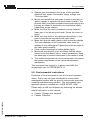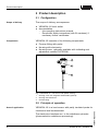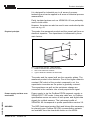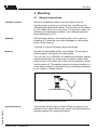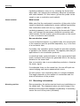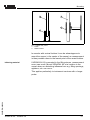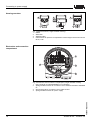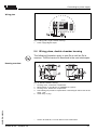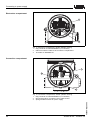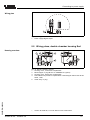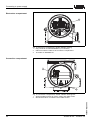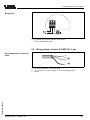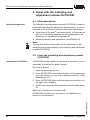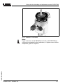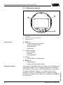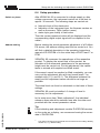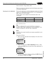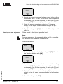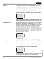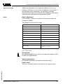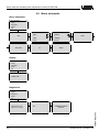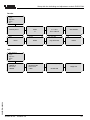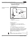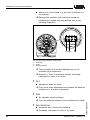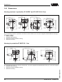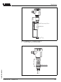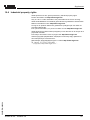
1
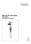
Operating Instructions
VEGACAL 62
Profibus PA
Contents
Contents
1
About this document
1.1
1.2
1.3
2
.
.
.
.
.
.
.
.
.
.
.
.
.
.
.
.
.
.
.
.
.
.
.
.
.
.
.
.
.
.
.
.
.
.
.
.
.
.
.
.
.
.
.
.
.
..
..
..
..
..
..
..
..
..
Configuration. . . . . . .
Principle of operation .
Adjustment . . . . . . . .
Storage and transport
.
.
.
.
.
.
.
.
.
.
.
.
.
.
.
.
.
.
.
.
.
.
.
.
.
.
.
.
.
.
.
.
.
.
.
.
.
.
.
.
.
.
.
.
.
.
.
.
.
.
.
.
.
.
.
.
.
.
.
.
.. 8
.. 8
. . 10
. . 10
.
.
.
.
.
.
.
.
General instructions . . . . . . . . . . . . . . . . . . . . . 11
Mounting information . . . . . . . . . . . . . . . . . . . . 12
Preparing the connection . . . . . . . . . . . . . .
Connection steps. . . . . . . . . . . . . . . . . . . .
Wiring plans, single chamber housing . . . . .
Wiring plans, double chamber housing . . . .
Wiring plans, double chamber housing Exd .
Wiring plans, version IP 66/IP 68, 1 bar . . .
.
.
.
.
.
.
..
..
..
..
..
..
15
16
17
19
21
23
Setup with the indicating and adjustment module
PLICSCOM
6.1
6.2
Short description . .
Insert the indicating
PLICSCOM . . . . . .
Adjustment system
Setup procedure . .
Menu schematic . .
..................
and adjustment module
..................
..................
..................
..................
. . . 24
.
.
.
.
..
..
..
..
24
26
27
31
VEGACAL 62 - Profibus PA
30025-EN-060224
6.3
6.4
6.5
2
.
.
.
.
.
.
.
.
.
Connecting to power supply
5.1
5.2
5.3
5.4
5.5
5.6
6
5
5
5
5
5
5
6
6
7
...
...
...
...
...
53.
...
...
...
Mounting
4.1
4.2
5
Authorised personnel . . . . . . . . .
Appropriate use. . . . . . . . . . . . .
Warning about misuse . . . . . . . .
General safety instructions . . . . .
CE conformity . . . . . . . . . . . . . .
Compatibility acc. to NAMUR NE
Safety information for Ex areas. .
Manufacturer declaration . . . . . .
Environmental instructions . . . . .
Product description
3.1
3.2
3.3
3.4
4
4
4
4
For your safety
2.1
2.2
2.3
2.4
2.5
2.6
2.7
2.8
2.9
3
Function . . . . . . . . . . . . . . . . . . . . . . . . . . . . .
Target group . . . . . . . . . . . . . . . . . . . . . . . . . .
Symbolism used . . . . . . . . . . . . . . . . . . . . . . .
Contents
7
Set up with PACTware™ and other adjustment
programs
7.1
7.2
7.3
7.4
8
.
.
.
.
.
.
.
.
.
.
.
.
..
..
..
..
34
34
35
35
.
.
.
.
.
.
.
.
.
.
.
.
.
.
.
..
..
..
..
..
36
36
39
40
40
Maintenance and fault rectification
8.1
8.2
8.3
8.4
8.5
9
Connecting the PC . . . . . . . . . . . . . . . .
Parameter adjustment with PACTware™ .
Parameter adjustment with PDM. . . . . . .
Saving the parameter adjustment data . .
Maintenance . . . . . . . . . . . . . . . . .
Fault rectification . . . . . . . . . . . . . .
Exchange of the electronics module
Shortening the probe . . . . . . . . . . .
Instrument repair . . . . . . . . . . . . . .
.
.
.
.
.
.
.
.
.
.
.
.
.
.
.
.
.
.
.
.
Dismounting
9.1
9.2
Dismounting steps . . . . . . . . . . . . . . . . . . . . . . 41
Disposal . . . . . . . . . . . . . . . . . . . . . . . . . . . . . 41
10 Supplement
Technical data. . . . . . . .
Profibus PA. . . . . . . . . .
Dimensions . . . . . . . . . .
Industrial property rights.
.
.
.
.
.
.
.
.
.
.
.
.
.
.
.
.
.
.
.
.
.
.
.
.
.
.
.
.
.
.
.
.
.
.
.
.
.
.
.
.
.
.
.
.
.
.
.
.
.
.
.
.
.
.
.
.
.
.
.
.
..
..
..
..
42
47
52
55
30025-EN-060224
10.1
10.2
10.3
10.4
VEGACAL 62 - Profibus PA
3
About this document
1 About this document
1.1 Function
This operating instructions manual has all the information you
need for quick setup and safe operation. Please read this
manual before you start setup.
1.2 Target group
This operating instructions manual is directed to trained,
qualified personnel. The contents of this manual should be
made available to these personnel and put into practice by
them.
1.3 Symbolism used
Information, tip, note
This symbol indicates helpful additional information.
Caution, warning, danger
This symbol informs you of a dangerous situation that could
occur. Ignoring this cautionary note can impair the person and/
or the instrument.
Ex applications
This symbol indicates special instructions for Ex applications.
l
List
The dot set in front indicates a list with no implied sequence.
à
Action
This arrow indicates a single action.
1
Sequence
Numbers set in front indicate successive steps in a procedure.
30025-EN-060224
4
VEGACAL 62 - Profibus PA
For your safety
2 For your safety
2.1 Authorised personnel
All operations described in this operating instructions manual
must be carried out only by trained specialist personnel
authorised by the operator. For safety and warranty reasons,
any internal work on the instruments must be carried out only
by personnel authorised by the manufacturer..
2.2 Appropriate use
VEGACAL 62 is a sensor for continuous level measurement.
Detailed information on the application range of VEGACAL 62
is available in chapter "Product description".
2.3 Warning about misuse
Inappropriate or incorrect use of the instrument can give rise to
application-specific hazards, e.g. vessel overfill or damage to
system components through incorrect mounting or adjustment.
2.4 General safety instructions
The VEGACAL 62 is a high-tech instrument requiring the strict
observance of standard regulations and guidelines. The user
must take note of the safety instructions in this operating
instructions manual, the country-specific installation standards
(e.g. the VDE regulations in Germany) as well as all prevailing
safety regulations and accident prevention rules.
2.5 CE conformity
VEGACAL 62 is in CE conformity with EMC (89/336/EWG) and
LVD (73/23/EWG).
30025-EN-060224
Conformity has been judged acc. to the following standards:
l
EMC:
- Emission EN 61326: 2004 (class B)
- Susceptibility EN 61326: 2004 including supplement A
l
LVD: EN 61010-1: 2001
2.6 Compatibility acc. to NAMUR NE 53
VEGACAL 62 meets NAMUR recommendation NE 53. VEGA
instruments are generally upward and downward compatible:
VEGACAL 62 - Profibus PA
5
For your safety
l
l
l
sensor software for DTM-VEGACAL 62 HART, PA or FF
DTM VEGACAL 62 for adjustment software PACTware™
adjustment module PLICSCOM for sensor software
The parameter adjustment of the basic sensor functions is
independent of the software version. The range of available
functions depends on the respective software version of the
individual components.
The software version of VEGACAL 62 can be determined as
follows:
l
l
l
via PACTware™
on the type label of the electronics
via the indicating and adjustment module PLICSCOM
You can view all software histories on our website www.vega.
com. Make use of this advantage and get registered for update
information via e-mail.
2.7 Safety information for Ex areas
Please note the Ex-specific safety information for installation
and operation in Ex areas. These safety instructions are part of
the operating instructions manual and come with the Exapproved instruments.
2.8 Manufacturer declaration
In conformity with DIN EN 60079-14/2004, para. 5.2.3, point
c1, the capacitive probe VEGACAL 62 is suitable for use in
zone 2.
The operator must use the instrument correctly and follow the
specifications of the following documents:
l
l
l
this operating instructions manual
this manufacturer declaration (24640)
the applicable installation regulations
Max. increase of the surface temperature during operation:
15 K (individual components in the instrument)
With an ambient temperature of +70°C (+158°F) on the
housing and a process temperature of +70°C (+158°F), the
max. ambient temperature during operation is +95°C (+203°F).
6
VEGACAL 62 - Profibus PA
30025-EN-060224
Measures to maintain the explosion protection during operation:
For your safety
l
l
l
l
l
l
l
l
Operate you instrument in the range of the specified
electrical limit values. Permissible supply voltage: see
"Technical data"
Mount and operate the instrument in such a way that no
ignition danger is expected by electrostatic charges. The
process fitting, the plastic-coated/covered probe part or the
housing are made of electrically non-conductive plastic
(depending on the version).
Make sure that the seal is mounted correctly between
lower part of the housing and cover. Screw the cover on
tightly.
Make sure that there is no explosive atmosphere, if you
want to operate the instrument with open cover
Make sure that the cable gland is tight and strain-relieved.
The outer diameter of the connection cable must be
adapted to the cable gland. Tighten the pressure screw of
the cable gland carefully.
Cover unused openings for cable glands tightly
Mount the instrument in such a position that the sensor
cannot touch the vessel wall or vessel installations. Keep
the influences of product movements in the vessel in mind.
The surface temperature on the housing must not exceed
the ignition temperature of the concerned explosive
atmosphere
This instrument was judged by a person that fulfils the
requirements acc. to DIN EN 60079-14.
2.9 Environmental instructions
Protection of the environment is one of our most important
duties. That is why we have introduced an environment
management system with the goal of continuously improving
company environmental protection. The environment management system is certified acc. to DIN EN ISO 14001.
Please help us fulfil this obligation by observing the environmental instructions in this manual:
l
Chapter "Storage and transport"
Chapter "Disposal"
30025-EN-060224
l
VEGACAL 62 - Profibus PA
7
Product description
3 Product description
3.1 Configuration
Scope of delivery
The scope of delivery encompasses:
l
l
Components
VEGACAL 62 level switch
documentation
- this operating instructions manual
- Ex-specific safety instructions (with Ex versions), if
necessary further certificates.
VEGACAL 62 consists of the following components:
l
l
l
Process fitting with probe
Housing with electronics
Housing cover, optionally available with indicating and
adjustment module PLICSCOM
1
2
3
Fig.
1
2
3
1: VEGACAL 62 - rod version with plastic housing
Housing cover with integrated PLICSCOM (optional)
Housing with electronics
Process fitting
3.2 Principle of operation
Area of application
The electronics functions acc. to the admittance principle
(phase-selective admittance processing).
8
VEGACAL 62 - Profibus PA
30025-EN-060224
VEGACAL 62 is a level sensor with partly insulated probe for
continuous level measurement.
Product description
It is designed for industrial use in all areas of process
technology and can be applied in all areas of industrial process
measurement.
Partly insulated probes such as VEGACAL 62 are preferably
used in bulk solids.
However, the probe can also be used in non-conductive liquids
such as e.g. oil.
Physical principle
The probe, the measured product and the vessel wall form an
electrical capacitor. The capacitance is influenced by three
main factors.
1
2
3
Fig.
1
2
3
2: Functional principle - Plate capacitor
Distance between the electrode surfaces
Size of the electrode surfaces
Type of dielectric between the electrodes
The probe and the vessel wall are the capacitor plates. The
measured product is the dielectric. Due to the higher dielectric
constant (DK value) of the product compared to air, the
capacitance increases as the probe is gradually covered.
30025-EN-060224
The capacitance as well as the resistance change are
converted in the oscillator into a level-proportional signal.
Power supply and bus communication
Power supply is via the Profibus DP/PA segment coupler or
VEGALOG 571 EP cards. A two-wire cable acc. to Profibus
specification serves as carrier of both power and digital data
signals for multiple sensors. The instrument profile of
VEGACAL 62 corresponds to profile specification version 3.0.
GSD/EDD
The GSD (instrument master files) and bitmap files necessary
for planning your Profibus-DP-(PA) communication network
are available from the download section on the VEGA
VEGACAL 62 - Profibus PA
9
Product description
homepage www.vega.com under "Services - Downloads Software - Profibus". There you can also find the appropriate
certificates. In a PDM environment, an EDD (Electronic Device
Description) is also required to enable the full range of sensor
functions (also available as a download).A CD with the
appropriate files can be ordered via e-mail under info@de.
vega.com or by phone from one of the VEGA agencies under
the order number "DRIVER.S".
3.3 Adjustment
VEGACAL 62 can be adjusted with three different adjustment
media:
l
l
l
the indicating and adjustment module PLICSCOM
with the suitable VEGA DTM in conjunection with an
adjustment software acc. to the FDT/DTM standard, e.g.
PACTware™ and PC
the Simatic adjustment program PDM
The entered parameters are generally saved in VEGACAL 62,
optionally also in PLICSCOM or in PACTware™.
3.4 Storage and transport
Packaging
Your instrument was protected by packaging during transport.
Its capacity to handle normal loads during transport is assured
by a test acc. to DIN EN 24180.
The packaging of standard instruments consists of environment-friendly, recyclable cardboard. For special versions, PE
foam or PE foil is also used. Dispose of the packaging material
via specialised recycling companies.
Storage and transport temperature
l
l
Storage and transport temperature see "Supplement Technical data - Ambient conditions"
Relative humidity 20 … 85 %
30025-EN-060224
10
VEGACAL 62 - Profibus PA
Mounting
4 Mounting
4.1 General instructions
Installaton location
Select an installation position you can easily reach for
mounting and connecting as well as later retrofitting of an
indicating and adjustment module. The housing can be rotated
by 330° without the use of any tools. You can also install the
indicating and adjustment module in four different positions
(each displaced by 90°).
Handling
With screwed versions, the housing must not be used for
screwing in! Tightening can cause damages on the locking
piston of the housing.
To screw in, use the hexagon above the thread.
Moisture
Use the recommended cables (see chapter "Connecting to
power supply") and tighten the cable gland.
You can give your VEGACAL 62 additional protection against
moisture penetration by leading the connection cable downward in front of the cable entry. Rain and condensation water
can thus drain off. This applies mainly to mounting outdoors, in
areas where moisture is expected (e.g. by cleaning processes)
or on cooled or heated vessels.
Fig. 3: Measures against moisture penetration
30025-EN-060224
Pressure/Vacuum
VEGACAL 62 - Profibus PA
The process fitting must be sealed if there is gauge or low
pressure in the vessel. Before use, check if the seal material is
resistant against the measured product.
11
Mounting
Insulating measures, such as e.g. covering the thread with
teflon tape, can interrupt the necessary electrical connection
with metal vessels. For this reason, ground the probe on the
vessel or use a conductive seal material.
Vessel material
Metal vessel
Make sure that the mechanical connection of the probe to the
vessel is electrically conductive to ensure sufficient grounding.
Use conductive seals such as e.g. copper or lead etc.
Insulating measures, such as covering the thread with Teflon
tape, can interrupt the necessary electrical connection with
metal vessels. For this reason, ground the probe on the vessel
or use a conductive seal material.
Non-conductive vessel
In non-conductive vessels, e.g. plastic tanks, the second pole
of the capacitor must be provided separately, e.g. in the form
of a concentric tube.
Vessel forms
If possible, the capacitive probe should be mounted vertically
or parallel to the counter electrode. This applies particularly to
applications in non-conductive products.
In cylindrical tanks, spherical tanks or other asymmetrical tank
forms, nonlinear level values are generated due to the varying
distance to the vessel wall.
Use a concentric tube in non-conductive products or linearize
the meas. signal.
Condensation
If condensate forms on the vessel top, the run-off liquid can
cause bridging and hence measurement errors.
For this reason, use a screening tube or a longer insulation.
The length depends on the amount of condensate and the
drain-off behaviour of the product.
4.2 Mounting information
Mounting position
VEGACAL 62 - Profibus PA
30025-EN-060224
12
During operation, the probe must not touch any installations or
the vessel wall. The measured value can also change if the
distance to the vessel wall changes considerably. If necessary,
secure the end of the probe (insulated).
Mounting
1
3
4
2
Fig. 4: Fasten the probe
1 Probe
2 Plastic sleeve
In vessels with conical bottom it can be advantageous to
mount the sensor in the center of the vessel, as measurement
is then possible down to the lowest point of the vessel bottom.
Inflowing material
If VEGACAL 62 is mounted in the filling stream, measurement
errors can result. Mount VEGACAL 62 at a location in the
vessel where no disturbing influence from e.g. filling openings,
agitators, etc. can occur.
30025-EN-060224
This applies particularly to instrument versions with a longer
probe.
VEGACAL 62 - Profibus PA
13
Mounting
Fig. 5: Inflowing material
30025-EN-060224
14
VEGACAL 62 - Profibus PA
Connecting to power supply
5 Connecting to power supply
5.1 Preparing the connection
Note safety instructions
Always observe the following safety instructions:
l
l
Connect only in the complete absence of line voltage
If overvoltages are expected, overvoltage arresters should
be installed acc. to Profibus specification.
Take note of safety
instructions for Ex
applications
In hazardous areas you should take note of the appropriate
regulations, conformity and type approval certificates of the
sensors and power supply units.
Select power supply
Power is supplied via a Profibus DP/PA segment coupler or a
VEGALOG 571 EP input card. The power supply range can
differ depending on the instrument version. The exact range is
stated in the "Technical data" in the "Supplement".
Select connection cable
VEGACAL 62 is connected with screened cable acc. to the
Profibus specification. Power supply and digital bus signal are
carried over the same two-wire connection cable.
An outer cable diameter of 5 … 9 mm ensures the seal effect
of the cable entry.
Please make sure that your installation is carried out acc. to
the Profibus specification. In particular, make sure that the
termination of the bus is done with appropriate terminating
resistors.
Cable gland ½ NPT
On VEGACAL 62 with cable gland ½ NPT and plastic housing,
a metal ½" threaded insert is moulded in the plastic housing.
Caution:
No grease should be used when screwing the NPT cable
gland or steel tube into the threaded insert. Standard grease
can contain additives affecting the connection between
threaded insert and housing. This will influence the stability of
the connection and the tightness of the housing.
30025-EN-060224
Cable screening and grounding
VEGACAL 62 - Profibus PA
In systems with potential equalisation, connect the cable
screen directly to ground potential at the power supply unit, in
the connection box and at the sensor. The screen in the sensor
must be connected directly to the internal ground terminal. The
ground terminal outside on the housing must be connected to
the potential equalisation (low impedance).
15
Connecting to power supply
In systems without potential equalisation, connect the cable
screen directly to ground potential at the power supply unit and
at the sensor. In the connection box or T-distributor, the screen
of the short stub to the sensor must not be connected to
ground potential or to another cable screen. The cable screens
to the power supply unit and to the next distributor must be
connected to each other and also connected to ground
potential via a ceramic capacitor (e.g. 1 nF, 1500 V). The low
frequency potential equalisation currents are thus suppressed,
but the protective effect against high frequency interference
signals remains.
The total capacitance of the cable and of all capacitors must
not exceed 10 nF in Ex applications.
Select connection
cable for Ex applications
Take note of the corresponding installation regulations for Ex
applications. In particular, make sure that no potential equalisation currents flow over the cable screen. In case of
grounding on both sides this can be achieved by the use of a
capacitor or a separate potential equalisation.
5.2 Connection steps
Proceed as follows:
1
Unscrew the housing cover
2
If an indicating and adjustment module is installed, remove
it by turning it slightly to the left.
3
Loosen compression nut of the cable entry
4
Remove approx. 10 cm (4 in) of the cable mantle, strip
approx. 1 cm (0.4 in) insulation from the ends of the
individual wires
5
Insert the cable into the sensor through the cable entry
6
Lift the opening levers of the terminals with a screwdriver
(see following illustration)
7
Insert the wire ends into the open terminals according to
the wiring plan
30025-EN-060224
16
VEGACAL 62 - Profibus PA
Connecting to power supply
Fig. 6: Connection steps 6 and 7
8
Press down the opening lever of the terminals, you will
hear the terminal spring closing.
9
Check the hold of the wires in the terminals by lightly
pulling on them
10 Connect the screen to the internal ground terminal and the
external ground terminal to potential equalisation
11 Tighten the compression nut of the cable entry, the seal
ring must completely encircle the cable
12 Screw the housing cover back on
The electrical connection is finished.
5.3 Wiring plans, single chamber housing
30025-EN-060224
The following illustrations apply to the non-Ex as well as to the
Ex ia version.
VEGACAL 62 - Profibus PA
17
Connecting to power supply
Housing overview
4
4
1
Fig.
1
2
3
4
4
2
3
7: Material versions, single chamber housing
Plastic
Aluminium
Stainless steel
Filter element for pressure compensation or blind stopper with version IP 66/
IP 68, 1 bar
Electronics and connection
compartment
Display
I2C
4
1
2
5 6 7 8
1
2
3
Fig. 8: Electronics and connection compartment, single chamber housing
1 Plug connector for VEGACONNECT (I²C interface)
2 Spring-loaded terminals for connection of the external indication VEGADIS
61
3 Ground terminal for connection of the cable screen
4 Spring-loaded terminals for power supply
30025-EN-060224
18
VEGACAL 62 - Profibus PA
Connecting to power supply
Wiring plan
Display
I2C
1
2
5
6
7
8
1
Fig. 9: Wiring plan, single chamber housing
1 Power supply/Signal output
5.4 Wiring plans, double chamber housing
The following illustration apply to non-Ex as well as Ex ia
versions. The Exd version is described in the next subchapter.
Housing overview
1
2
3
4
Fig.
1
2
3
4
30025-EN-060224
5
1)
VEGACAL 62 - Profibus PA
5
10: Double chamber housing
Housing cover, connection compartment
Blind stopper or plug M12x1 for VEGADIS 61 (option)
Housing cover, electronics compartment
Filter element for pressure compensation or blind stopper with version IP 66/
IP 68, 1 bar1)
Cable entry or plug
Version IP 66/IP 68, 1 bar not with four-wire instruments.
19
Connecting to power supply
Electronics compartment
1
Display
I2C
1
2
5 6 7 8
2
3
Fig.
1
2
3
11: Electronics compartment, double chamber housing
Plug connector for VEGACONNECT (I²C interface)
Internal connection cable to the connection compartment
Terminals for VEGADIS 61
Display
Connection compartment
1
3
1
2
I2C
2
Fig.
1
2
3
12: Connection compartment, double chamber housing
Plug connector for VEGACONNECT (I²C interface)
Ground terminal for connection of the cable screen
Spring-loaded terminals for power supply
30025-EN-060224
20
VEGACAL 62 - Profibus PA
Connecting to power supply
Wiring plan
I2C
1
2
1
Fig. 13: Wiring plan, double chamber housing
1 Power supply/Signal output
5.5 Wiring plans, double chamber housing Exd
Housing overview
1
2
3
4
Fig.
1
2
3
4
30025-EN-060224
5
2)
VEGACAL 62 - Profibus PA
5
14: Double chamber housing
Housing cover, connection compartment
Blind stopper or plug M12x1 for VEGADIS 61 (option)
Housing cover, electronics compartment
Filter element for pressure compensation or blind stopper with version IP 66/
IP 68, 1 bar2)
Cable entry or plug
Version IP 66/IP 68, 1 bar not with four-wire instruments.
21
Connecting to power supply
Electronics compartment
1
Display
I2C
1
2
5 6 7 8
2
3
Fig.
1
2
3
15: Electronics compartment, double chamber housing
Plug connector for VEGACONNECT (I²C interface)
Internal connection cable to the connection compartment
Terminals for VEGADIS 61
Connection compartment
1
1 2
2
Fig. 16: Connection compartment, double chamber housing Exd
1 Spring-loaded terminals for power supply and cable screen
2 Ground terminal for connection of the cable screen
30025-EN-060224
22
VEGACAL 62 - Profibus PA
Connecting to power supply
Wiring plan
1
2
1
Fig. 17: Wiring plan, double chamber housing Exd
1 Power supply/Signal output
5.6 Wiring plans, version IP 66/IP 68, 1 bar
Wire assignment, connection
cable
+
1
2
30025-EN-060224
Fig. 18: Wire assignment, connection cable
1 br (+) and bl (-) for power supply or to the processing system
2 Screen
VEGACAL 62 - Profibus PA
23
Setup with the indicating and adjustment module PLICSCOM
6 Setup with the indicating and
adjustment module PLICSCOM
6.1 Short description
Function/Configuration
The indicating and adjustment module PLICSCOM is used for
measured value display, adjustment and diagnosis. It can be
mounted in the following housing versions and instruments:
l
l
All sensors of the plics® instrument family, in the single as
well as in the double chamber housing (optionally in the
electronics or connection compartment)
External indicating and adjustment unit VEGADIS 61
Note:
You will find detailed information on the adjustment in the
operating instructions manual of the indicating and adjustment
module PLICSCOM.
6.2 Insert the indicating and adjustment module
PLICSCOM
Insert/remove PLICSCOM
PLICSCOM can be inserted or removed at any time. It is not
necessary to interrupt the power supply.
Proceed as follows:
1
Unscrew the housing cover
2
Place PLICSCOM in the desired position on the electronics
(you can choose any one of four different positions - each
displaced by 90°)
3
Press PLICSCOM lightly onto the electronics and turn it to
the right until it snaps in.
4
Screw housing cover with inspection window tightly back
on
Removal is carried out in reverse order.
PLICSCOM is powered by the sensor, an additional connection is not necessary.
30025-EN-060224
24
VEGACAL 62 - Profibus PA
Setup with the indicating and adjustment module PLICSCOM
Fig. 19: Installation of PLICSCOM
30025-EN-060224
Note:
If you intend to retrofit VEGACAL 62 with a PLICSCOM for
continuous measured value indication, a higher cover with an
inspection glass is required.
VEGACAL 62 - Profibus PA
25
Setup with the indicating and adjustment module PLICSCOM
6.3 Adjustment system
2
1
1.1
3
Key functions
Adjustment system
20: Indicating and adjustment elements
LC display
Indication of the menu item number
Adjustment keys
l
[OK] key:
- move to the menu overview
- confirm selected menu
- edit parameter
- save value
l
[->] key to select:
- menu change
- list entry
- editing position
l
[+] key:
- modify value of a parameter
l
[ESC] key:
- interrupt input
- jump to the next higher menu
The sensor is adjusted via the four keys of the indicating and
adjustment module. The LC display indicates the individual
menu items. The functions of the individual keys are shown in
the above illustration. Approx. 10 minutes after the last
pressing of a key, an automatic reset to measured value
indication is triggered. Any values not confirmed with [OK] will
not be saved.
VEGACAL 62 - Profibus PA
30025-EN-060224
26
Fig.
1
2
3
Setup with the indicating and adjustment module PLICSCOM
6.4 Setup procedure
Switch on phase
After VEGACAL 62 is connected to voltage supply or after
voltage recurrence, the instrument carries out a self-test for
approx. 30 seconds. The following steps are carried out:
l
l
l
Internal check of the electronics
Indication of the instrument type, the firmware version as
well as the sensor TAGs (sensor name)
status byte goes briefly to fault value
Then the current measured value will be displayed and the
corresponding digital output signal will be outputted to the
cable.3)
Address setting
Before starting the actual parameter adjustment of a Profibus
PA sensor, the address setting must first be carried out. You
will find a detailed description in the operating instructions
manual of PLICSCOM or in the online help of PACTware™ or
DTM.
Parameter adjustment
VEGACAL 62 measures the capacitance of the respective
product. To display the actual level of the product, an
allocation of the measured capacitance to the percentage
height must be carried out. For this adjustment, the capacitance is entered with emptied and filled vessel.
If the vessel cannot be emptied or filled completely, you can
carry out the adjustment also with two known levels - for
example with 10 % and 90 %. The difference between the
empty and full adjustment values should be as large as
possible.
The actual level can then be calculated on the basis of these
settings.
VEGACAL 62 must be installed. A change of level is
necessary for this adjustment.
In the main menu item "Basic adjustment", the individual
submenu items should be selected one after the other and
provided with the correct parameter values.
30025-EN-060224
Tip:
If the indicating and adjustment module PLICSCOM remains
on the probe as a display, we recommend saving the sensor
data in PLICSCOM.
3)
VEGACAL 62 - Profibus PA
The values correspond to the actual level as well as to the settings already
carried out, e.g. default setting.
27
Setup with the indicating and adjustment module PLICSCOM
Use the function "Copy sensor data".
Start your parameter adjustment with the following menu items
of the basic adjustment:
Carrying out min. adjustment
To be on the safe side, note the adjustment values for full and
empty. If an adjustment procedure fails, it is not necessary to
again carry out a level change.
These values can be helpful if the electronics has to be
exchanged.
%
Value
Empty adjustment
Full adjustment
Tab. 2: Adjustment protocol
Tip:
For min. adjustment the vessel should be as empty as
possible, and for max. adjustment, as full as possible. If the
vessel is already full, start with max. adjustment.
Note:
If possible, the vessel should be as empty as possible for min.
adjustment.
Proceed as follows:
1
▶
2
Move from the measured value display to the main menu
by pushing [OK].
Basic adjustment
Display
Diagnostics
Service
Info
Select the menu item "Basic adjustment" with [->] and
confirm with [OK]. Now the menu item "Min. adjustment" is
displayed.
3
28
Prepare the adjustment value for editing with [OK]. Move to
the selection window with [OK].
VEGACAL 62 - Profibus PA
30025-EN-060224
Min. adjustment
0.00 %
=
0.0 pF
54.5 pF
Setup with the indicating and adjustment module PLICSCOM
Min. adjustment
Accept current measured value?
accept?
Edit?
Carrying out max. adjustment
4
Accept the current measured value or move to the editing
window with "Edit". To edit, set the cursor to the requested
position with [->]. Set the requested % value with [+] and
save with [OK]. The cursor jumps to the capacitance value.
5
Enter the current capacitance value in pF (displayed
below) for the empty vessel corresponding to the percentage value.
6
Save the settings with [OK] and move to "Max. adjustment"
with [->].
Fill the vessel to the highest possible level.
Note:
For max. adjustment, the vessel should be as full as possible.
This will make the calibration more accurate.
Proceed as follows:
Max. adjustment
100.00 %
=
1000.0 pF
327.4 pF
1
Prepare the adjustment value for editing with [OK]. Move to
the selection window with [OK].
Min. adjustment
Accept current measured value?
30025-EN-060224
accept?
Edit?
VEGACAL 62 - Profibus PA
2
Accept the current measured value or move to the editing
window with "Edit". To edit, set the cursor to the requested
position with [->]. Set the requested % value with [+] and
save with [OK]. The cursor jumps to the capacitance value.
3
Enter the current capacitance value in pF (displayed
below) for the full vessel corresponding to the percentage
value.
4
Save the settings with [OK].
29
Setup with the indicating and adjustment module PLICSCOM
Damping
To suppress fluctuation in the measured value display, e.g.
caused by an agitated product surface, an integration time can
be set. This time can be between 0 and 999 seconds. Keep in
mind that this setting will increase the reaction time of the
measurement, and that the reaction to quick changes of the
measured value will be delayed. In general, a time of a few
seconds is sufficient to smooth the measured value display.
Damping
0s
Enter the requested parameter via the appropriate keys, save
your settings and jump to the next menu item with the [->] key.
Linearization curve
A linearization is necessary for all vessels in which the vessel
volume does not increase linearly with the level - e.g. with a
cylindrical or spherical tank - and the indication or output of the
volume is required. Corresponding linearization curves are
preprogrammed for these vessels. They represent the
correlation between the level percentage and vessel volume.
By activating the appropriate curve, the volume percentage of
the vessel is displayed correctly. If the volume should not be
displayed in percent but e.g. in l or kg, a scaling can be also
set in the menu item "Display".
Linearization curve
linear
Enter the requested parameter via the appropriate keys, save
your settings and jump to the next menu item with the [->] key.
Sensor-TAG
In this menu item you can enter an unambiguous designation
for the sensor, e.g. the measurement loop name or the tank or
product designation. In digital systems and in the documentation of larger plants, a singular designation should be entered
for exact identification of individual measuring sites.
Sensor-TAG
Sensor
30
VEGACAL 62 - Profibus PA
30025-EN-060224
With this menu item, the Basic adjustment is finished and you
can now jump to the main menu with the [ESC] key.
Setup with the indicating and adjustment module PLICSCOM
Optional settings
Additional adjustment and diagnosis options such as e.g.
scaling, simulation or trend curve presentation are shown in
the following menu schematic. You will find a detailed
description of these menu items in the operating instructions
manual of the indicating and adjustment module.
Reset
Basic adjustment
If the function "Reset" is carried out, the sensor resets all
settings to default.
The following values will be reset:
Function
Reset value
Max. adjustment
3000 pF
Min. adjustment
0 pF
Integration time ti
0s
Linearization
linear
Sensor-TAG
Sensor
Display
PA-Out 1
Channel (PV)
lin %
Addtl. PA value (PV)
lin %
Out-Scale (unit)
%
PV Out-Scale
0.00 lin-% = 0.0 %
100.0 lin-% = 100 %
Tab. 3: Reset values
Information:
All additional settings are reset to the standard values of the
Profibus PA specification.
Special parameters
All special parameters are reset to delivery status.
30025-EN-060224
Peak values
The min. and max. values are reset to the current value.
VEGACAL 62 - Profibus PA
31
Setup with the indicating and adjustment module PLICSCOM
6.5 Menu schematic
Basic adjustment
▶
Basic adjustment
Display
Diagnostics
Service
Info
Sensor address
1
1.1
000
Channel
1.5
Min. adjustment
0.00 %
=
0.0 pF
82.5 pF
1.2
Damping
1.6
PV lin.value
0s
Max. adjustment
100.00 %
=
1000.0 pF
327.4 pF
1.3
Sensor-TAG
1.7
Linearization curve
1.4
linear
Sensor
Display
▶
Basic adjustment
Display
Diagnostics
Service
Info
Displayed value
2
2.1
Primary value
Diagnostics
▶
Basic adjustment
Display
Diagnostics
Service
Info
Peak values
Capacit. min: 65.7 pF
Capacit. max: 782.4 pF
3
3.1
Sensor status
OK
3.2
Trend recording
3.3
Presentation of the output trend
30025-EN-060224
32
VEGACAL 62 - Profibus PA
Setup with the indicating and adjustment module PLICSCOM
Service
▶
Basic adjustment
Display
Diagnostics
Service
Info
Additional PA value
4
4.1
Out-Scale-Units
Secondary value 1
Reset
4.2
Volume
hl
4.5
Reset?
Language
PV-/Out-Scale Min.
4.3
Simulation
0 % = 5.0 hl
100 % = 5000.0 hl
4.6
Deutsch
Copy sensor data
4.4
Start simulation?
4.7
Copy sensor data?
PIN
4.8
Enable?
Info
▶
Basic adjustment
Display
Diagnostics
Service
Info
5.1
Date of manufacture
04. February 2005
Software version
4.10/00
5.2
Date of last change using PC
5.3
Sensor characteristics
5.4
Display now?
04. March 2005
30025-EN-060224
Device type
VEGACAL 6x
Serial number
12345678
5
VEGACAL 62 - Profibus PA
33
Set up with PACTware™ and other adjustment programs
7 Set up with PACTware™ and other
adjustment programs
7.1 Connecting the PC
Connecting the PC directly to
the sensor
VEGACONNECT 3
PACTwareTM/
3
>PA<
1
=
~
2
Fig.
1
2
3
Power supply
21: PC connected directly to the sensor
RS232 connection
VEGACAL 62
I²C adapter cable for VEGACONNECT 3
Necessary components:
l
l
l
l
VEGACAL 62
PC with PACTware™ and suitable VEGA-DTM
VEGACONNECT 3 with I²C adapter cable (article no.
2.27323)
Power supply unit
7.2 Parameter adjustment with PACTware™
Further setup steps are described in the operating instructions
manual "DTM Collection/PACTware™" attached to each CD
and which can also be downloaded from our homepage. A
detailed description is available in the online help of
PACTware™ and the VEGA-DTMs.
34
VEGACAL 62 - Profibus PA
30025-EN-060224
Note:
Keep in mind that for setup of VEGACAL 62, DTM-Collection
04/2005 or a newer version must be used.
Set up with PACTware™ and other adjustment programs
All currently available VEGA-DTMs are provided in the DTM
Collection on CD and can be obtained from the responsible
VEGA agency for a token fee. This CD includes also the up-todate PACTware™ version. The basic version of this DTM
Collection incl. PACTware™ is also available as a free-ofcharge download from the Internet.
Go via www.vega.com and "Downloads" to the item "Software".
7.3 Parameter adjustment with PDM
For VEGA sensors device descriptions for the adjustment
program PDM are also available as EDD. The device
descriptions are already implemented in the current versions
of PDM. For older versions of PDM they are available as a
free-of-charge download from the Internet.
Go via www.vega.com and "Downloads" to the item "Software".
7.4 Saving the parameter adjustment data
It is recommended to document or save the parameter
adjustment data. They are hence available for multiple use or
service purposes.
30025-EN-060224
The VEGA DTM Collection and PACTware™ in the licensed,
professional version offer the suitable tools for a systematic
project documentation and recording.
VEGACAL 62 - Profibus PA
35
Maintenance and fault rectification
8 Maintenance and fault rectification
8.1 Maintenance
When used as directed in normal operation, VEGACAL 62 is
completely maintenance-free.
8.2 Fault rectification
Causes of malfunction
VEGACAL 62 offers maximum reliability. Nevertheless faults
can occur during operation. These may be caused by the
following, e.g.:
l
l
l
l
Sensor
Process
Supply
Signal processing
Fault rectification
The first measures to be taken are to check the output signals
as well as to evaluate the error messages via the indicating
and adjustment module PLICSCOM. The procedure is
described below. Further comprehensive diagnostics can be
carried out on a laptop with the software PACTware™ and the
suitable DTM. In many cases, the causes can be determined in
this way and faults can be rectified.
24 hour service hotline
Should the following measures not be successful, please call
in urgent cases the VEGA service hotline under the phone
number +49 1805 858550.
The hotline is available to you 7 days a week round-the-clock.
Since we offer this service world-wide, the support is only
available in the English language. The service is free of
charge, only the standard telephone costs will be charged.
Checking Profibus PA
?
When connecting an additional instrument, the segment
fails.
l Max. supply current of the segment coupler exceeded
à Measure the current consumption, reduce size of
segment
?
Wrong presentation of the measured value in Simatic S5
the measured value
à Insert converting component from Siemens
36
VEGACAL 62 - Profibus PA
30025-EN-060224
l Simatic S5 cannot interpret the number format IEEE of
Maintenance and fault rectification
?
In Simatic S7 the measured value is always presented as 0
l Only four bytes are consistently loaded in the PLC
à Use function component SFC 14 to load 5 bytes
consistently.
?
Measured value on PLICSCOM does not correspond to the
PLC
l In the menu item "Display - Display value" is not set to
"PA-Out"
à Check values and correct, if necessary
?
No connection between PLC and PA network
l Incorrect adjustment of the bus parameter and the
segment coupler-dependent baud rate
à Check values and correct, if necessary
?
Instrument does not appear during connection setup
l Profibus DP cable pole-reversed
à Check cable and correct, if necessary
l Incorrect termination
à Check termination at the beginning and end points of
the bus and terminate, if necessary, acc. to the
specification
l Instrument not connected to the segment, double
assignment of an address
à Check and correct, if necessary
In Ex applications, the regulations for the wiring of intrinsically
safe circuits must be observed.
Error message via PLICSCOM
?
E013
l no measured value available
à Shortcircuit due to bridging of conductive buildup
between process fitting and probe
30025-EN-060224
à Remove buildup - if necessary, mount a protective tube
VEGACAL 62 - Profibus PA
37
Maintenance and fault rectification
l Shortcircuit in the probe, e.g. because of moisture in
the housing
à Remove the oscillator and check the resistance
between the marked plug connections acc. to the
following illustration
1 2
Fig.
1
2
3
3
22: Check the resistance in the probe
Screening
Probe
Ground potential
à There should be no contact between any of the
terminals (high resistance)
à However, if there is somehow contact, exchange
instrument or return it for repair
?
E017
l Adjustment span too small
à Carry out a fresh adjustment and increase the distance
between min. and max. adjustment
?
E036
l No operable sensor software
à Carry out software update or send instrument for repair
E041/E042/E043
l Hardware error, electronics defective
à Exchange instrument or return it for repair
38
VEGACAL 62 - Profibus PA
30025-EN-060224
?
Maintenance and fault rectification
?
E113
l Communication conflict
à Exchange instrument or return it for repair
8.3 Exchange of the electronics module
If the electronics module is defective, it can be replaced by the
user.
In Ex applications, only an instrument and an electronics
module with appropriate Ex approval may be used.
If there is no electronics module available on site, one can be
ordered from the VEGA agency serving you.
Sensor serial number
The order data of the sensor must be loaded into the new
electronics module. This can be done:
l
l
at the factory by VEGA personnel
or on site by the user
In both cases, the sensor serial number is necessary. The
serial numbers are stated on the type label of the instrument or
on the delivery note.
Information:
When loading on site, the order data must be downloaded from
the Internet (see Operating Instructions manual of the
oscillator).
Assignment
The oscillators are adapted to the respective sensor and differ
in their signal output or in their power supply. You can find a
suitable oscillator in the following overview.
The oscillators differ only in their signal output and are suitable
for all series 60 sensors.
The following types are available:
l
l
l
CL-E60H (4 … 20 mA/HART)
CL-E60P (Profibus PA)
CL-E60F (Foundation Fieldbus)
30025-EN-060224
In Ex applications, only electronics with appropriate Ex
approval must be used.
VEGACAL 62 - Profibus PA
39
Maintenance and fault rectification
8.4 Shortening the probe
The probe (rod) can be shortened by any length.
1
Shorten the rod with a cut-off wheel or metal saw at the
lower end. Make sure the length is correct before shortening.
2
Carry out a new adjustment.
8.5 Instrument repair
If it is necessary to repair, please proceed as follows:
You can download a return form (23 KB) in the Internet from
our home page www.vega.com under: "Downloads - Forms
and Certificates - Repair form".
By doing this you help us carry out the repair quickly and
without having to call back for needed information.
l
l
l
l
Print and fill out one form per instrument
Clean the instrument and pack it damage-proof
Attach the completed form and possibly also a safety data
sheet to the instrument
Please ask the responsible agency for the address of the
return shipment!
30025-EN-060224
40
VEGACAL 62 - Profibus PA
Dismounting
9 Dismounting
9.1 Dismounting steps
Warning:
Before dismounting, be aware of dangerous process conditions such as e.g. pressure in the vessel, high temperatures,
corrosive or toxic products etc.
Take note of the instructions in chapters "Mounting" and
"Connecting to power supply" and carry out the listed steps in
reverse order.
9.2 Disposal
VEGACAL 62 consists of materials which can be recycled by
specialised recycling companies. We use recyclable materials
and have designed the electronic modules to be easily
separable.
WEEE directive 2002/96/EG
This instrument is not subject to the WEEE directive 2002/96/
EG and the respective national laws (in Germany, e.g.
ElektroG). Pass the instrument directly on to a specialised
recycling company and do not use the municipal collecting
points. These may be used only for privately used products
acc. to the WEEE directive.
Correct disposal avoids negative effects to persons and
environment and ensures recycling of useful raw materials.
Materials: see "Technical data"
30025-EN-060224
If you cannot dispose of the instrument properly, please
contact us about disposal methods or return.
VEGACAL 62 - Profibus PA
41
Supplement
10 Supplement
10.1 Technical data
General data
Material 316L corresponds to 1.4404 or 1.4435
Materials, wetted parts
- Process fitting - Thread
316L
-
Process fitting - Flange
316L
-
Process seal
Klingersil C-4400
-
insulation (partly insulated)
PTFE
-
Probe (rod PTFE partly insulated
ø 12 mm/ø 0.47 in)
316L
Materials, non-wetted parts
- Housing
Plastic PBT (Polyester), Alu die-casting powder-coated, 316L
-
Seal ring between housing and
housing cover
NBR (stainless steel housing), silicone (Alu/
plastic housing)
-
Ground terminal
316L
Weights
- with plastic housing
1150 g (40 oz)
-
with Aluminium housing
1600 g (56 oz)
-
with stainless steel housing
1950 g (69 oz)
-
Rod weight ø 12 mm (ø 0.47 in)
900 g/m (10 oz/ft)
Sensor length (L)
Max. lateral load
Max. torque (process fitting thread)
0.2 … 6 m (0.7 … 20 ft)
10 Nm (7.4 lbf ft)
100 Nm (73 lbf ft)
Output variable
Output signal
Sensor address
Current value
Integration time (63 % of the input
variable)
Rise time
digital output signal, format acc. to IEEE-754
126 (default setting)
constantly 10 mA; ±0.5 mA
0 … 999 s, adjustable
500 ms (ti: 0 s, 0 … 100 %)
30025-EN-060224
42
VEGACAL 62 - Profibus PA
Supplement
Input variable
Parameter
Measuring principle
Measuring range
Frequency
level of non-conductive liquids and solids
phase-selective admittance processing (PSA)
0 … 3000 pF
270 kHz
Accuracy (similar to DIN EN 60770-1)
Reference conditions acc. to DIN EN 61298-1
- Temperature
+18 … +30°C (+64 … +86°F)
-
Relative humidity
45 … 75 %
-
Atmospheric pressure
860 … 1060 mbar/86 … 106 kPa
(12.5 … 15.4 psi)
Temperature error
- <120 pF
<1 pF
-
1 % of the current measured value
>120 pF
Linearity error
<0.25 % of the complete measuring range
Characteristic curve deviation and measurement characteristics
Temperature drift
0.06 %/10 K relating to the max. measuring
range
Ambient conditions
Ambient, storage and transport temperature
- without indicating and adjustment
module
-40 … +80°C (-40 … +176°F)
-
-20 … +70°C (-4 … +158°F)
with indicating and adjustment
module
Process conditions
-1 … 64 bar/-100 … 6400 kPa (-14.5 … 928 psi)
-50 … +150°C (-58 … +302°F)
-50 … +200°C (-58 … +392°F)
30025-EN-060224
Process pressure
Process temperature VEGACAL 62 of
316L
Process temperature (thread or flange
temperature) with temperature adapter
(option)
VEGACAL 62 - Profibus PA
43
Supplement
2
3
80˚C
(176˚F)
40˚C
(104˚F)
-50˚C
(-58˚F)
0˚C
(32˚F)
1
50˚C
(122˚F)
100˚C
(212˚F)
150˚C
(302˚F)
200˚C
(392˚F)
-40˚C
(-40˚F)
Fig.
1
2
3
23: Ambient temperature - Product temperature
Product temperature
Ambient temperature
Temperature range with temperature adapter
Dielectric figure (DK value)
>1.5
Electromechanical data - version IP 66/IP 67 and IP 66/IP 68; 0.2 bar
Cable entry/plug4)
- Single chamber housing
l
or:
l
1x cable entry M20x1.5 (cable-ø 5 … 9 mm),
1x blind stopper M20x1.5
1x closing cap ½ NPT, 1x blind plug ½ NPT
or:
-
Double chamber housing
l
1x plug (depending on the version), 1x blind
plug M20x1.5
l
1x cable entry M20x1.5 (cable-ø 5 … 9 mm),
1x blind stopper M20x1.5; plug M12x1 for
VEGADIS 61 (optional)
or:
l
1x closing cap ½ NPT, 1x blind stopper
½ NPT, plug M12x1 for VEGADIS 61
(optional)
or:
l
for wire cross sections up to 2.5 mm²
4)
44
Depending on the version M12x1, acc. to DIN 43650, Harting, AmphenolTuchel, 7/8" FF
VEGACAL 62 - Profibus PA
30025-EN-060224
Spring-loaded terminals
1x plug (depending on the version), 1x blind
stopper M20x1.5; plug M12x1 for VEGADIS
61 (optional)
Supplement
Electromechanical data - version IP 66/IP 68, 1 bar
Cable entry
- Single chamber housing
l
1x IP 68 cable entry M20x1.5; 1x blind
stopper M20x1.5
or:
-
Double chamber housing
l
1x closing cap ½ NPT, 1x blind plug ½ NPT
l
1x IP 68 cable entry M20x1.5; 1x blind
stopper M20x1.5; plug M12x1 for VEGADIS
61 (option)
or:
l
Connection cable
- Configuration
1x closing cap ½ NPT, 1x blind stopper
½ NPT, plug M12x1 for VEGADIS 61
(optional)
four cores, one suspension cable, one breather
capillary, screen braiding, foil, mantle
-
wire cross section
0.5 mm²
-
wire resistance
<0.036 Ohm/m
-
tensile load
>1200 N (270 pounds force)
-
Standard length
5 m (16.4 ft)
-
Max. length
1000 m (3280 ft)
-
Min. bending radius
25 mm (at +25°C/+77°F)
-
Diameter
approx. 8 mm
-
Colour - standard PE
Black
-
Colour - standard PUR
Blue
-
Colour - Ex version
Blue
Indicating and adjustment module
Power supply and data transmission
Indication
Adjustment elements
Protection
- unassembled
30025-EN-060224
-
mounted into the sensor without
cover
VEGACAL 62 - Profibus PA
through sensor via gold-plated sliding contacts
(I²C bus)
LC display in dot matrix
4 keys
IP 20
IP 40
45
Supplement
Materials
- Housing
ABS
-
Polyester foil
Inspection window
Voltage supply
Supply voltage
- non-Ex instrument
9 … 32 V DC
-
9 … 24 V DC
EEx ia instrument
Power supply by/max. number of sensors
- DP/PA segment coupler
max. 32 (max. 10 with Ex)
-
max. 15 (max. 10 with Ex)
VEGALOG 571 EP card
Electrical protective measures
Protection
- Plastic housing
IP 66/IP 67
-
Alu and stainless steel standard
IP 66/IP 68 (0.2 bar)5)
-
Alu and stainless housing, optionally
available
IP 66/IP 68 (1 bar)
Overvoltage category
Protection class
III
II
Approvals6)
ATEX II 1G, 1/2G, 2G EEx ia IIC T6
ATEX II 1/2G, 2G EEx d ia IIC T67)
ATEX II 1/2D 2D IP6X T8)
WHG
Ship approvals
6)
7)
8)
46
Requirement to maintain the protection is the suitable cable.
Deviating data with Ex applications: see separate safety instructions.
Only in conjunction with Aluminium double chamber housing.
Not in conjunction with plastic housing.
VEGACAL 62 - Profibus PA
30025-EN-060224
5)
Supplement
10.2 Profibus PA
Instrument master file
The instrument master file (GSD) contains the characteristic data of the Profibus PA
instrument. These data are, e.g. the permissible transmission rates as well as information on
diagnostics values and the format of the measured value outputted by the PA instrument.
A bitmap file is also provided for the planning tool of the Profibus network. This file is
automatically installed with the GSD file. The bitmap file is used for symbolic indication of the
PA instrument in the configuration tool.
Ident number
Each Profibus instrument gets an unambiguous ident number (ID number) from the Profibus
user organisation (PNO). This ID number is also included in the name of the GSD file. For
VEGACAL 62 the ID number is 0x076(hex) and the GSD file „CL__076E.GSD“. Optionally to
this manufacturer-specific GSD file, PNO provides also a general so-called profile-specific
GSD file. For VEGACAL 62 you have to use the general GSD file „PA139700.GSD“. If the
general GSD file is used, the sensor must be set to the profile-specific ident number via the
DTM software. By default, the sensor operates with the manufacturer-specific ID number.
30025-EN-060224
Cyclical data traffic
The master class 1 (e.g. PLC) cyclically reads out measured values from the sensor during
operation. The below block diagram below shows which data can be accessed by the PLC.
VEGACAL 62 - Profibus PA
47
Supplement
Min-Max
adjustment
Sensor
characteristics
Linearization
%
pF
Lin%
TB
Secondary
Value 1
Secondary
Value 2
Primary
Value
PROFIBUS PA-output
Source for
scaling
Scaling
Damping
Alarms
Failure
mode
Target
Mode
PA-Out
ti
FB
Select additional cyclic
value
Fig. 24: VEGACAL 62: Block diagram with AI (PA-OUT) value and additional cyclical value
TB Transducer Block
FB Function Block
Module of the PA sensors
For the cyclic data traffic, VEGACAL 62 provides the following modules:
l
AI (PA-OUT)
- PA-OUT value of the FB1 after scaling
l
Additional Cyclic Value
- Additional cyclical value (depending on the source)
l
Free Place
- This module must be used if a value in the data telegram of the cyclical data traffic
should not be used (e.g. replacement of the Additional Cyclic Value)
Max. three modules can be active. By means of the configuration software of the Profibus
master, you can determine the configuration of the cyclical data telegram with these modules.
The procedure depends on the respective configuration software.
Note:
The modules are available in two versions:
l
48
Short for Profibus master which support only one „Identifier
Format“ byte, e.g. Allen Bradley
Long for Profibus master only supporting the "Identifier
Format" byte, e.g. Siemens S7-300/400
VEGACAL 62 - Profibus PA
30025-EN-060224
l
Supplement
Examples of telegram configuration
In the following you will see how the modules can be combined and how the appendant data
telegram is structured.
Example 1 (standard setting) with distance value and additional cyclical value:
l
l
AI (PA-OUT)
Additional Cyclic Value
Byte-No.
Format
Value
1
2
3
4
IEEE-754Floating point value
PA-OUT
(FB1)
5
Status
Status
(FB1)
6
7
8
9
IEEE-754Floating point value
Additional Cyclic
Value
10
Status
Status
Example 2 with distance value without additional cyclic value:
l
l
AI (PA-OUT)
Free Place
Byte-No.
Format
Value
1
2
3
4
IEEE-754Floating point value
PA-OUT
(FB1)
5
Status
Status
(FB1)
Data format of the output signal
Byte4 Byte3 Byte2 Byte1 Byte0
Status
Value (IEEE-754)
Fig. 25: Data format of the output signal
The status byte corresponds to profile 3.0 "Profibus PA Profile for Process Control Devices"
coded. The status "Measured value OK" is coded as 80 (hex) (Bit7 = 1, Bit6 … 0 = 0).
30025-EN-060224
The measured value is transferred as a 32 bit floating point number in the IEEE-754 format.
VEGACAL 62 - Profibus PA
49
Supplement
Byte n+2
Byte n+3
Byte n
Byte n+1
Bit Bit Bit Bit Bit Bit Bit Bit Bit Bit Bit Bit Bit Bit Bit Bit Bit Bit Bit Bit Bit Bit Bit Bit Bit Bit Bit Bit Bit Bit Bit Bit
7 6 5 4 3 2 1 0 7 6 5 4 3 2 1 0 7 6 5 4 3 2 1 0 7 6 5 4 3 2 1 0
VZ 27 26 25 24 23 22 21 20 2-1 2-2 2-3 2-4 2-5 2-6 2-7 2-8 2-9 2-10 2-11 2-12 2-13 2-14 2-15 2-16 2-17 2-18 2-19 2-20 2-21 2-22 2-23
Sign
Significant
Significant
Exponent
Significant
Bit
Value = (-1)VZ
2 (Exponent - 127)
(1 + Significant)
Fig. 26: Data format of the measured value
Coding of the status byte associated with the PA output value
Status
code
Description acc. to Profibus
standard
possible cause
0x00
bad - non-specific
Flash-Update active
0x04
bad - configuration error
l
l
l
l
0x0C
bad - sensor failure
l
l
l
l
Adjustment error
Configuration error with PV-Scale (PV-Span too small)
Unit irregularity
Error in the linearization table
Hardware error
Converter error
Leakage pulse error
Trigger error
Measured value generation error
0x10
bad - sensor failure
l
0x1f
bad - out of service constant
"Out of Service" mode switched on
0x44
uncertain - last unstable value
Failsafe replacement value (Failsafe-Mode = "Last value" and already
valid measured value since switching on)
0x48
uncertain substitute set
l
l
Switch on simulation
Failsafe replacement value (Failsafe-Mode = "Fsafe value")
0x4c
uncertain - initial value
0x51
uncertain - sensor; conversion not Sensor value < lower limit
accurate - low limited
0x52
uncertain - sensor; conversion not Sensor value > upper limit
accurate - high limited
0x80
good (non-cascade) - OK
0x84
good (non-cascade) – active block Static revision (FB, TB) changed (10 sec. active, after the parameter of
alarm
the static category was written)
0x89
good (non-cascade) – active advisory alarm – low limited
Lo-Alarm
0x8a
good (non-cascade) – active advisory alarm – high limited
Hi-Alarm
0x8d
good (non-cascade) – active critical alarm – low limited
Lo-Lo-Alarm
OK
30025-EN-060224
50
Failsafe replacement value (Failsafe-Mode = "Last valid value" and no
valid measured value since switching on)
VEGACAL 62 - Profibus PA
Supplement
Description acc. to Profibus
standard
0x8e
good (non-cascade) – active critical alarm – high limited
possible cause
Hi-Hi-Alarm
30025-EN-060224
Status
code
VEGACAL 62 - Profibus PA
51
Supplement
10.3 Dimensions
Housing versions in protection IP 66/IP67 and IP 66/IP 68; 0.2 bar
~ 69mm
(2 23/32")
~ 69mm
(2 23/32")
ø 77mm
(3 1/32")
~ 87mm (3 27/64")
ø 84mm
(3 5/16")
ø 77mm
(3 1/32")
~ 116mm (4 9/16")
ø 84mm (3 5/16")
M20x1,5/
½ NPT
M20x1,5/
½ NPT
1
116mm (4 9/16")
120mm (4 23/32")
112mm (4 13/32")
117mm (4 39/64")
M16x1,5
M20x1,5/
½ NPT
M20x1,5/
½ NPT
2
3
M20x1,5
4
Fig. 27: Housing versions in protection IP 66/IP 67 and IP 66/IP 68; 0.2 bar (with integrated PLICSCOM the housing is
9 mm/0.35 in higher)
1 Plastic housing
2 Stainless steel housing
3 Aluminium double chamber housing
4 Aluminium housing
Housing in protection IP 66/IP 68, 1 bar
~ 103mm
(4 1/16")
~ 105mm (4 9/64")
ø 84mm
(3 5/16")
ø 77mm
(3 1/32")
~ 150mm (5 29/32")
ø 84mm (3 5/16")
116mm (4 9/16")
120mm (4 23/32")
117mm (4 39/64")
M16x1,5
M20x1,5
M20x1,5
1
M20x1,5/
½ NPT
2
M20x1,5
3
Fig. 28: Housing versions in protection IP 66/IP 68, 1 bar (with integrated PLICSCOM the housing is 9 mm/0.35 in higher)
1 Stainless steel housing
2 Aluminium double chamber housing
3 Aluminium housing
30025-EN-060224
52
VEGACAL 62 - Profibus PA
G 3/4 A, G 1 A, G 11/2 A
ø16mm (5/8")
L
100mm
(3 15/16")
22
2 1/4"
56 mm
(2 1/4")
Supplement
12mm (15/32")
30025-EN-060224
73mm (2 7/8")
Fig. 29: VEGACAL 62 - Threaded version G1
L = Sensor length, see "Technical data"
ø 40mm (1 37/64")
Fig. 30: Temperature adapter
VEGACAL 62 - Profibus PA
53
Supplement
30025-EN-060224
54
VEGACAL 62 - Profibus PA
Supplement
10.4 Industrial property rights
VEGA product lines are global protected by industrial property rights.
Further information see http://www.vega.com.
Only in U.S.A.: Further information see patent label at the sensor housing.
VEGA Produktfamilien sind weltweit geschützt durch gewerbliche Schutzrechte.
Nähere Informationen unter http://www.vega.com.
Les lignes de produits VEGA sont globalement protégées par des droits de
propriété intellectuelle.
Pour plus d'informations, on pourra se référer au site http://www.vega.com.
VEGA lineas de productos están protegidas por los derechos en el campo de la
propiedad industrial.
Para mayor información revise la pagina web http://www.vega.com.
Линии продукции фирмы ВЕГА защищаются повсему миру правами на
интеллектуальную собственность.
Дальнейшую информациюсмотрите на сайте http://www.vega.com.
30025-EN-060224
保。
(VEGA)系列品在全球享有知
德
一步信息
网站<http://www.vega.com>。
VEGACAL 62 - Profibus PA
55
VEGA Grieshaber KG
Am Hohenstein 113
77761 Schiltach
Germany
Phone +49 7836 50-0
Fax +49 7836 50-201
E-mail: [email protected]
www.vega.com
ISO 9001
All statements concerning scope of delivery, application,
practical use and operating conditions of the sensors and
processing systems correspond to the information available at the time of printing.
© VEGA Grieshaber KG, Schiltach/Germany 2006
Technical data subject to alterations
30025-EN-060224