1
Drive Technology \ Drive Automation \ System Integration \ Services
Compact Operating Instructions
MOVIDRIVE® MDX60B / 61B
Edition 05/2010
16920813 / EN
SEW-EURODRIVE—Driving the world
Contents
Contents
1
2
General Information ............................................................................................ 4
1.1
Scope of this documentation....................................................................... 4
1.2
Structure of the safety notes ....................................................................... 4
Safety Notes ........................................................................................................ 5
2
3
2.1
General information .................................................................................... 5
2.2
Target group ............................................................................................... 5
2.3
Designated use ........................................................................................... 6
2.4
Transportation, storage ............................................................................... 6
2.5
Installation ................................................................................................... 7
2.6
Electrical connection ................................................................................... 7
2.7
Safe disconnection...................................................................................... 7
2.8
Operation .................................................................................................... 8
Installation ........................................................................................................... 9
3.1
4
5
7
Wiring diagram for basic unit ...................................................................... 9
Startup................................................................................................................ 14
4.1
General startup instructions ...................................................................... 14
4.2
Operation of MOVITOOLS® MotionStudio................................................ 15
Operation ........................................................................................................... 18
5.1
6
................................................................................................................... 5
Operating displays .................................................................................... 18
5.2
Information messages............................................................................... 19
5.3
Memory card ............................................................................................. 20
Service ............................................................................................................... 22
6.1
Error information ....................................................................................... 22
6.2
Error messages and list of errors .............................................................. 23
6.3
SEW electronics service ........................................................................... 39
6.4
Extended storage...................................................................................... 39
6.5
Disposal .................................................................................................... 40
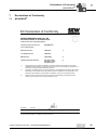
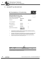
Declarations of Conformity .............................................................................. 41
7.1
MOVIDRIVE® ............................................................................................ 41
7.2
MOVIDRIVE® with DFS11B/DFS21B ....................................................... 42
7.3
MOVIDRIVE® with DCS21B/DCS31B ...................................................... 43
Compact Operating Instructions – MOVIDRIVE® MDX60B/61B
3
General Information
Scope of this documentation
1
1
General Information
1.1
Scope of this documentation
This documentation comprises the general safety notes and selected information regarding the MOVIDRIVE® MDX60B/61B inverter.
1.2
•
Please note that this documentation does not replace the detailed operating
instructions.
•
Read the detailed operating instructions before you start working with MOVIDRIVE®
MDX60B/61B.
•
Observe the information, instructions and notes in the detailed operating instructions.
This is essential for fault-free operation of the unit and fulfillment of any rights to claim
under guarantee.
•
The enclosed CD or DVD contains PDF files of the detailed operating instructions as
well as other MOVIDRIVE® MDX60B/61B documentation.
•
All technical documentation from SEW-EURODRIVE is available for download in
PDF on the SEW-EURODRIVE website: www.sew-eurodrive.com
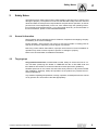
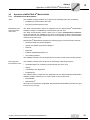
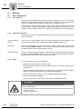
Structure of the safety notes
The safety notes in these operating instructions are designed as follows:
Pictogram
SIGNAL WORD
Type and source of danger.
Possible consequence(s) if disregarded.
•
Pictogram
Example:
Measure(s) to prevent the danger.
Signal word
Meaning
Consequences if
disregarded
DANGER
Imminent danger
Severe or fatal injuries
WARNING
Possible dangerous situation
Severe or fatal injuries
CAUTION
Possible dangerous situation
Minor injuries
NOTICE
Possible damage to property
Damage to the drive system or its environment
INFORMATION
Useful information or tip.
Simplifies the handling of the
drive system.
General danger
Specific danger,
e.g. electric shock
4
Compact Operating Instructions – MOVIDRIVE® MDX60B/61B
Safety Notes
2
2
Safety Notes
The following basic safety notes must be read carefully to prevent injury to persons and
damage to property. The operator must ensure that the basic safety notes are read and
observed. Make sure that persons responsible for the plant and its operation, as well as
persons who work independently on the unit, have read through the operating instructions carefully and understood them. If you are unclear about any of the information in
this documentation, please contact SEW-EURODRIVE.
2.1
General information
Never install or start up damaged products. Submit a complaint to the shipping company
immediately in the event of damage.
During operation, drive inverters can have live, bare and movable or rotating parts as
well as hot surfaces, depending on their degree of protection.
Removing covers without authorization, improper use as well as incorrect installation or
operation may result in severe injuries to persons or damage to property.
Refer to the documentation for additional information.
2.2
Target group
Only qualified electricians are authorized to install, startup or service the units or correct unit faults (observing IEC 60364 or CENELEC HD 384 or DIN VDE 0100 and
IEC 60664 or DIN VDE 0110 as well as national accident prevention guidelines).
Qualified personnel in the context of these basic safety notes are: All persons familiar
with installation, assembly, startup and operation of the product who possess the necessary qualifications.
Any activities regarding transportation, storage, operation, and disposal must be carried
out by persons who have been instructed appropriately.
Compact Operating Instructions – MOVIDRIVE® MDX60B/61B
5
Safety Notes
Designated use
2
2.3
Designated use
Drive inverters are components intended for installation in electrical systems or machines.
In case of installation in machines, startup of the inverters (meaning the start of designated use) is prohibited until it is determined that the machine meets the requirements
stipulated in the Machinery Directive 2006/42/EC; EN 60204 must be observed.
Startup (i.e. the start of designated use) is only permitted under observance of the EMC
(2004/108/EC) directive.
The drive inverters meet the requirements stipulated in low voltage guideline 2006/95/
EC. The harmonized standards of the EN 61800-5-1/DIN VDE T105 series in connection with EN 60439-1/VDE 0660 part 500 and EN 60146/VDE 0558 are applied to these
drive inverters.
You must observe the technical data and information on the connection requirements
as provided on the nameplate and in the documentation.
2.3.1
Safety functions
MOVIDRIVE® MDX60/61B inverters may not perform safety functions without higherlevel safety systems. Use higher-level safety systems to ensure protection of equipment
and personnel.
For safety applications, refer to the information in the following publications:
2.4
•
Safe disconnection for MOVIDRIVE® MDX60B/61B – Conditions
•
Safe disconnection for MOVIDRIVE® MDX60B/61B – Applications
Transportation, storage
Observe the notes on transportation, storage and proper handling. Observe the climatic
conditions as stated in the section "General technical data".
6
Compact Operating Instructions – MOVIDRIVE® MDX60B/61B
Safety Notes
Installation
2.5
2
Installation
The units must be installed and cooled according to the regulations and specifications
in the corresponding documentation.
Protect the drive inverters from excessive strain. Ensure that components are not deformed and/or insulation spaces are maintained, particularly during transportation.
Avoid contact with electronic components and contacts.
Drive inverters contain components that can be damaged by electrostatic energy and
improper handling. Prevent mechanical damage or destruction of electric components
(may pose health risk).
The following applications are prohibited unless the unit is explicitly designed for such
use:
2.6
•
Use in potentially explosive atmospheres.
•
Use in areas exposed to harmful oils, acids, gases, vapors, dust, radiation, etc.
•
Use in non-stationary applications which are subject to mechanical vibration and
impact loads in excess of the requirements in EN 61800-5-1.
Electrical connection
Observe the applicable national accident prevention guidelines when working on live
drive inverters (for example, BGV A3).
Electrical installation is to be carried out in compliance with pertinent regulations (e.g.
cable cross sections, fusing, protective conductor connection). For any additional information, refer to the applicable documentation.
You will find notes on EMC compliant installation, such as shielding, grounding, arrangement of filters and routing of lines, in the documentation of the drive inverters. Always
observe these notes even with drive inverters bearing the CE marking. The manufacturer of the system or machine is responsible for maintaining the limits established by
EMC legislation.
Protective measures and protection devices must comply with the regulations in force
(e.g. EN 60204 or EN 61800-5-1).
Required preventive measure: Grounding the unit.
MOVIDRIVE® B, size 7 has an additional display LED under the lower front cover. The
lit display LED indicates a DC link voltage. Do not touch power connections. Check that
there is no voltage present before touching power connections even if the LED display
indicates that there is no voltage.
2.7
Safe disconnection
The unit meets all requirements for safe disconnection of power and electronic connections in accordance with EN 61800-5-1. All connected circuits must also satisfy the requirements for safe disconnection.
Compact Operating Instructions – MOVIDRIVE® MDX60B/61B
7
Safety Notes
Operation
2
2.8
Operation
Systems with integrated drive inverters must be equipped with additional monitoring and
protection devices, if necessary, according to the applicable safety guidelines, such as
legislation governing technical equipment, accident prevention regulations, etc. The operating software may be used to make changes to the drive inverter.
Do not touch live components or power connections immediately after disconnecting the
drive inverters from the supply voltage because there may still be some charged capacitors. Note the respective reference plates on the drive inverter.
Keep all covers and doors closed during operation.
The fact that the status LED and other display elements (such as the display LED on
size 7 units) are no longer illuminated does not indicate that the unit has been disconnected from the power supply and no longer carries any voltage.
Check that there is no voltage present before touching power connections even if the
LED display indicates that there is no voltage.
Mechanical blocking or internal safety functions of the unit can cause a motor standstill.
Eliminating the cause of the problem or performing a reset may result in the drive restarting automatically. If, for safety reasons, this is not permitted for the driven machine,
disconnect the unit from the supply system before correcting the error.
8
Compact Operating Instructions – MOVIDRIVE® MDX60B/61B
Installation
Wiring diagram for basic unit
3
Installation
3.1
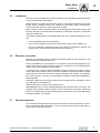
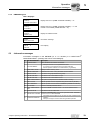
Wiring diagram for basic unit
3.1.1
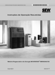
Power section and brake (size 1-6)
3
L1
L2
L3
PE
F11/F12/F13
K11
(AC-3)
Protective earth (shield)
L1 L2
UAC
UAC
UAC
F14/F15
F14/F15
K11
(AC-3)
K11
(AC-3)
L3
Line filter option NF...
L1' L2' L3'
F14/F15
DC link
connection *
L1 L2 L3
-UZ +UZ
X1:
X4:
Power section
K11
(AC-3)
X2:
DBØØ
DGND
DBØØ
K12
(AC-3)
U
DBØØ
V
X3:
W
PE
+R -R
K12
(AC-3)
DGND
1
BMK 2
3
4
13
14
15
PE
1
BE 2
BG 3
BGE 4
5
Section “Braking resistor
connection
BW.../BW..-T/BW...-P”
DGND
white
red
blue
Brake connector** CT/CV/DR/DT/DV:
Cutoff in the DC and AC
circuits
1
BE 2
BG 3
BGE 4
5
white
red
blue
M
3-phase
CT/CV/DR/DT/DV:
Cutoff in the AC
circuit
CT/CV, CM71 ... 112: Cutoff in the DC and AC circuits
1805559691
*
**
With sizes 1, 2 and 2S, there is no PE connection next to the supply system connection terminals and motor connection terminals (X1, X2). In this case, use the PE terminal next to the DC link connection (X4).
You must adhere to the connection sequence of the brake connector. Incorrect connection will cause irreparable damage to the brake. Read the operating instructions for the motors when connecting the brake using
the terminal box.
INFORMATION
•
•
Connect the brake rectifier using a separate supply system lead.
Supply via the motor voltage is not permitted!
Always switch off the brake on the DC and AC sides with:
– all hoist applications,
– Drives that require a rapid brake response time
– CFC and SERVO operating modes
Compact Operating Instructions – MOVIDRIVE® MDX60B/61B
9
Installation
Wiring diagram for basic unit
3
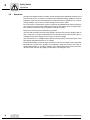
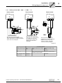
3.1.2
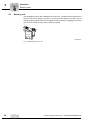
Power section and DC power supply unit (size7)
For connecting the brake, refer to the wiring diagram of size 1-6.
L1
L2
L3
PE
L1
L2
L3
PE
F11/F12/F13
F11/F12/F13
K11
(AC-3)
L1 L2
L3
NF... line filter option
L1' L2' L3'
10 11 12
X1:
Power
supply
unit
9
L1 L2 L3
L1 L2 L3
Power section
X2:
U
V
X3:
W
PE
+R -R
Section “Connection
of braking resistor
BW.../BW..-T/BW...-P”
M
3-phase
2079053451
Technical data of
DC power supply
unit:
•
Rated current: AC 2.4 A
•
Inrush current AC 30 A / AC 380 - 500 V
INFORMATION
Note that the connection of external +24 V power supply units to the X10:9 control terminal is not permitted in backup mode via power supply unit. Incorrect connection
prompts an error message.
3.1.3
Brake rectifier in the control cabinet
Install the connection cables between the brake rectifier and the brake separately from
other power cables when installing the brake rectifier in the control cabinet. Joint installation is only permitted with shielded power cables.
10
Compact Operating Instructions – MOVIDRIVE® MDX60B/61B
Installation
Wiring diagram for basic unit
3.1.4
3
Braking resistor BW... / BW...-...-T /BW...-...-P
Power section
Power section
X3:
Power section
X3:
X3:
PE
PE
PE
+R -R
+R -R
+R -R
F16
Wirkt
auf K11
BW...-...-P
97
F16
98
4
BW...-...-T
95
T2
RB1
affects
K11
affects
K11
96
T1
6
BW...
RB2
When the signal contact F16 trips,
K11 must be opened and DIØØ"/Controller
inhibit" must receive a "0" signal. The resistor
circuit must not be interrupted!
When the internal temperature
switch trips, K11 must be opened
and DIØØ"/Controller inhibit"
must receive a "0" signal. The
resistor circuit must not be
interrupted!
When the external bimetal relay
(F16) trips, K11 must be opened and
DIØØ "/Controller inhibit" must
receive a "0" signal . The resistor
circuit must not be interrupted!
1805563147
Overload protection
Braking resistor type
Design specified
Internal temperature switch
(..T)
External bimetallic relay
(F16)
Required
BW...
-
-
BW...-...-T
-
One of the two options (internal temperature switch/external
bimetallic relay) is required.
BW...-003 / BW...-005
Adequate
-
Permitted
BW090-P52B
Adequate
-
-
Compact Operating Instructions – MOVIDRIVE® MDX60B/61B
11
Installation
Wiring diagram for basic unit
3
3.1.5
Description of terminal functions on the basic unit (power section and control unit)
Terminal
Function
X1:1/2/3
X2:4/5/6
X3:8/9
X4:
L1/L2/L3 (PE)
U/V/W (PE)
+R/-R (PE)
+UZ/-UZ (PE)
Supply system connection
Motor connection
Braking resistor connection
DC link connection
9,10,11,12
L1/L2/L3/PE
Connection of switched-mode power supply (only for size 7)
S11:
S12:
S13:
Change I-signal DC(0(4)...20 am) ↔ V-signal DC(-10 V...0...10 V, 0...10 V), factory setting to V signal.
Switching system bus terminating resistor on/off; factory setting: OFF.
Set baud rate for the RS485 interface XT.
Either 9.6 or 57.6 baud, factory setting: 75.6 baud.
Switch frequency input on or off, factory setting: switched off.
S14:
X12:1
X12:2
X12:3
DGND
SC11
SC12
Reference potential system bus
System bus high
System bus low
X11:1
X11:2/3
X11:4
X11:5
REF1
AI11/12
AGND
REF2
DC+10 V (max. DC 3 am) for setpoint potentiometer
Setpoint input n1 (differential input or input with AGND reference potential), signal form → P11_/ S11
Reference potential for analog signals (REF1, REF2, AI.., AO..)
DC–10 V (max. DC 3 mA) for setpoint potentiometer
X13:1
X13:2
X13:3
X13:4
X13:5
X13:6
DIØØ
DIØ1
DIØ2
DIØ3
DIØ4
DIØ5
Binary input 1, with fixed assignment "/Controller
inhibit"
Binary input 2, factory setting "CW/stop"
Binary input 3, factory setting "CCW/stop"
Binary input 4, factory setting "Enable/stop"
Binary input 5, factory setting "n11/n21"
Binary input 6, factory setting "n12/n22"
X13:7
DCOM
Reference for binary inputs X13:1 to X13:6 (DIØØ to DIØ5) and X16:1/X16:2 (DIØ6 to DIØ7)
• Switching binary inputs with DC+24 V external voltage: Connection X13:7 (DCOM) must be connected
to the reference potential of the external voltage.
– Without jumper X13:7-X13:9 (DCOM-DGND) → Isolated binary inputs
– With jumper X13:7-X13:9 (DCOM-DGND) → Non-isolated binary inputs
•
12
•
•
The binary inputs are electrically isolated by
optocouplers.
Selection options for binary inputs 2 to 6 (DIØ1
... DIØ5) → Parameter menu P60_
The binary inputs must be switched with DC+24 V from X13:8 or X10:8 (VO24) → Jumper required
X13:7-X13:9 (DCOM-DGND).
X13:8
X13:9
X13:10
X13:11
VO24
DGND
ST11
ST12
Auxiliary supply output DC+24 V (max. load X13:8 and X10:8 = 400 mA) for external command switches
Reference potential for binary signals
RS485+ (baud rate has a fixed setting of 9.6 kBaud)
RS485-
X16:1
X16:2
X16:3
X16:4
X16:5
DIØ6
DIØ7
DOØ3
DOØ4
DOØ5
X16:6
DGND
Binary input 7, factory setting "No function"
Binary input 8, factory setting "No function"
Binary output 3, factory setting "IPOS output"
Binary output 4, factory setting "IPOS output"
Binary output 5, factory setting "IPOS output"
Do not connect external voltage to binary outputs
X16:3 (DOØ3) and X16:5 (DOØ5)!
Reference potential for binary signals
•
•
•
The binary inputs are electrically isolated by
optocouplers.
Selection options for binary inputs 7 to 8 (DIØ6/
DIØ7) → Parameter menu P60_
Selection options for binary outputs 3 to 5
(DOØ3...DOØ5) → Parameter menu P62_
Compact Operating Instructions – MOVIDRIVE® MDX60B/61B
Installation
Wiring diagram for basic unit
Terminal
Function
X10:1
X10:2
X10:3
TF1
DGND
DBØØ
X10:4
X10:5
X10:6
X10:7
DOØ1-C
DOØ1-NO
DOØ1-NC
DOØ2
X10:8
X10:9
X10:10
VO24
VI24
DGND
Auxiliary supply output DC+24 V (max. load X13:8 and X10:8 = 400 mA) for external command switches
Input DC+24 V voltage supply (backup voltage depending on options, unit diagnosis when supply system
off)
Reference potential for binary signals
Note for X:10.9: Only connect external backup voltage DC +24 V to sizes 0-6. With size 7, the DC
power supply unit must be connected to the supply system. Refer to section "Power section and DC
power supply unit (size 7)" (page 10).
X17:1
X17:2
X17:3
X17:4
DGND
VO24
SOV24
SVI24
Reference potential for X17:2
Auxiliary supply voltage DC+24 V, only to supply X17:4 on the same unit
Reference potential for DC+24 V "safe stop" input (safety contact)
DC+24 V "safe stop" input (safety contact)
XT
3
KTY+/TF-/TH connection (connect to X10:2 via TF/TH), factory set to "No response" (→ P835)
Reference potential for binary signals / KTY–
Binary output DBØØ with fixed assignment "/Brake", load capacity max DC 150 mA (short-circuit proof, protected against external voltage to DC 30 V)
Shared contact binary output 1, factory setting "Ready"
Normally open contact binary output 1, max. load of relay contacts DC 30 V and DC 0.8 A
NC contact binary output 1
Binary output DBØ2, factory set to "/Fault", max. load capacity DC 50 mA (short-circuit proof, protected
against external voltage to DC 30 V). Selection options for binary outputs 1 and 2 (DOØ1 and DOØ2) →
Parameter menu P62_. Do not apply external voltage to binary outputs X10:3 (DBØØ) and X10:7 (DOØ2).
Only service interface. Option slot: DBG60B / UWS21B / USB11A
Compact Operating Instructions – MOVIDRIVE® MDX60B/61B
13
Startup
General startup instructions
4
4
Startup
4.1
General startup instructions
DANGER
Uncovered power connections.
Severe or fatal injuries from electric shock.
•
•
4.1.1
Install the touch guard according to the regulations.
Never start the unit if the touch guard is not installed.
Requirements
The drive must be configured correctly to ensure that startup is successful. Refer to the
MOVIDRIVE® MDX60/61B system manual for detailed project planning notes and an
explanation of the parameters.
14
Compact Operating Instructions – MOVIDRIVE® MDX60B/61B
Operation of
MOVITOOLS®
4.2
Operation of MOVITOOLS® MotionStudio
4.2.1
Via MOVITOOLS® MotionStudio
Tasks
Establishing communication with
other units
Startup
MotionStudio
4
The software package enables you to perform the following tasks with consistency:
•
Establishing communication with units
•
Executing functions with the units
The SEW Communication Server is integrated into the MOVITOOLS® MotionStudio
software package for establishing communication with the units.
The SEW Communication Server allows you to create communication channels.
Once the channels are established, the units communicate via these communication
channels using their communication options. You can operate up to four communication
channels at the same time.
MOVITOOLS® MotionStudio supports the following types of communication channels:
•
Serial (RS-485) via interface adapters
•
System bus (SBus) via interface adapters
•
Ethernet
•
EtherCAT
•
Fieldbus (PROFIBUS DP/DP-V1)
•
Tool Calling Interface
The available channels can vary depending on the units and its communication options.
Executing functions with the units
The software package offers uniformity in executing the following functions:
•
Parameterization (for example in the parameter tree of the unit)
•
Startup
•
Visualization and diagnostics
•
Programming
The following basic components are integrated into the MOVITOOLS® MotionStudio
software package, allowing you to use the units to execute functions:
•
MotionStudio
•
MOVITOOLS®
All functions communicate using tools. MOVITOOLS® MotionStudio provides the right
tools for every unit type.
Compact Operating Instructions – MOVIDRIVE® MDX60B/61B
15
I
4
0
Startup
Operation of MOVITOOLS® MotionStudio
Technical support
SEW-EURODRIVE offers you a 24-hour service hotline.
Simply dial (+49) 0 18 05 and then enter the letters SEWHELP via the telephone keypad. Of course, you can also dial (+49) 0 18 05 - 7 39 43 57.
Online help
After installation, the following types of help are available to you:
•
This documentation is displayed in a help window after you start the software.
If the help window does not appear at the start, deactivate the "Display" control field,
in the menu under [Settings] / [Options] / [Help].
If the help window appears again, activate the "Display" control field, in the menu under [Settings] / [Options] / [Help].
•
16
Context-sensitive help is available for the fields which require you to enter values.
For example, you can use the <F1> key to display the ranges of values for the unit
parameters.
Compact Operating Instructions – MOVIDRIVE® MDX60B/61B
Operation of
4.2.2
MOVITOOLS®
Startup
MotionStudio
I
4
0
First steps
Starting the software and creating
a project
Proceed as follows to start MOVITOOLS® MotionStudio and create a project:
1. Start the MOVITOOLS® MotionStudio from the Windows start menu via:
[Start]/[Programs]/[SEW]/[MOVITOOLS-MotionStudio]/[MOVITOOLS-MotionStudio]
2. Create a project with name and storage location.
Establishing communication and
scanning the network
Proceed as follows to establish a communication with MOVITOOLS® MotionStudio and
scan your network:
1. Set up a communication channel to communicate with your units.
For detailed information on how to configure a communication channel, see the section regarding the relevant communication type.
2. Scan your network (unit scan). Press the [Start network scan] button [1] in the toolbar.
[1]
1132720523
1. Select the unit you want to configure.
2. Right-click to open the context menu.
As a result you will see a number of unit-specific tools to execute various functions
with the units.
Starting up the
units (online)
Proceed as follows to start up the units (online):
1. Switch to the network view.
2. Click on "Switch to online mode" [1] in the toolbar.
[1]
1184030219
[1] "Switch to online mode" symbol
3. Select the unit you want to startup.
4. Open the context menu and select the command [Startup] / [Startup].
The Startup wizard opens.
5. Follow the instructions of the startup wizard and then load the startup data onto your
unit.
Compact Operating Instructions – MOVIDRIVE® MDX60B/61B
17
I
5
Operation
Operating displays
0
5
Operation
5.1
Operating displays
5.1.1
7-segment display
The 7-segment display shows the operating condition of MOVIDRIVE® and, in the event
of an error, an error or warning code.
7-segment display
Unit status
(high byte in status word
1)
Meaning
0
0
24 V operation (inverter not ready)
1
1
Controller inhibit active
2
2
No enable
3
3
Standstill current
4
4
Enable
5
5
n-control (speed control)
6
6
M-control (torque control)
7
7
Hold control
8
8
Factory setting
9
9
Limit switch contacted
A
10
Technology option
c
12
IPOSplus® reference travel
d
13
Flying start
E
14
Calibrate encoder
F
Error number
Error display (flashing)
H
Status display
Manual operation
t
16
Inverter is waiting for data
U
17
"Safe Stop" active
² (blinking dot)
-
IPOSplus® program is running
Flashing display
-
STOP via DBG60B
-
RAM defective
1 ... 9
WARNING
Incorrect interpretation of display U = "Safe stop" active.
Severe or fatal injuries.
The display U = "Safe stop" is not safety-related and must not be used as a safety
function.
18
Compact Operating Instructions – MOVIDRIVE® MDX60B/61B
Operation
Information messages
I
5
0
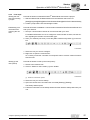
5.1.2
DBG60B keypad
Basic displays:
0.00rpm
0.000Amp
CONTROLLER INHIBIT
Display when X13:1 (DIØØ "/CONTROL.INHIBIT") = "0".
0.00rpm
0.000Amp
NO ENABLE
Display when X13:1 (DIØØ "/CONTROL.INHIBIT") = "1" and
inverter is not enabled ("ENABLE/STOP" = "0").
950.00rpm
0.990Amp
ENABLE (VFC)
Display for enabled inverter.
NOTE 6:
VALUE TOO HIGH
(DEL)=Quit
ERROR
9
STARTUP
5.2
Information message
Error display
Information messages
Information messages on the DBG60B (ca. 2 s in duration) or in MOVITOOLS®
MotionStudio/SHELL (message that can be acknowledged):
No.
Text DBG60B/SHELL
Description
1
ILLEGAL INDEX
Index addressed via interface not available.
2
NOT IMPLEMENT.
•
•
•
3
READ ONLY VALUE
Attempt to edit a read-only value.
4
PARAM. INHIBITED
Parameter lock P 803 = "ON", parameter cannot be altered.
5
SETUP ACTIVE
You tried to change parameters during setup.
6
VALUE TOO HIGH
You tried to enter a value that is too high.
7
VALUE TOO LOW
You tried to enter a value that is too low.
8
REQ. CARD MISSING
The option card required for the selected function is missing.
10
ONLY VIA ST1
Manual operation must be completed using X13:ST11/ST12 (RS 485).
11
ONLY TERMINAL
Manual operation must be exited via TERMINAL (DBG60B or UWS21B).
12
NO ACCESS
Access to selected parameter denied.
13
CTRL. INHIBIT MISSING
Set terminal DIØØ "/Controller inhibit" = "0" for the selected function.
14
INVALID VALUE
You tried to enter an invalid value.
16
PARAM. NOT LOCKED
Overflow of EEPROM buffer, e.g., due to cyclic write access. Parameter
not stored in non-volatile EEPROM.
17
INVERTER ENABLED
•
•
Attempt to execute a non-implemented function.
An incorrect communication service has been selected.
Manual operation selected via invalid interface (e.g. fieldbus).
Parameter to be changed can only be set in the state "CONTROLLER
INHIBIT".
Attempt to change to manual mode during enabled operation.
Compact Operating Instructions – MOVIDRIVE® MDX60B/61B
19
Operation
Memory card
5
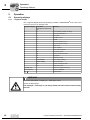
5.3
Memory card
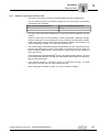
The pluggable memory card is installed in the basic unit. The basic data is stored on the
memory card and is always up-to-date. If a unit has to be replaced, the plant can be
started up again quickly without PC and data backup by simply re-plugging the memory
card. You can install as many option cards as required.
1810728715
Fig. 34: MDX60B/61B memory card
20
Compact Operating Instructions – MOVIDRIVE® MDX60B/61B
Operation
Memory card
5.3.1
5
Notes for replacing the memory card
•
Only plug in the memory card when the MOVIDRIVE® B unit is switched off.
•
You can install the memory card from the original unit in a new inverter. The following
combinations are permitted:
•
Original unit MOVIDRIVE® MDX60B/61B...
New inverter MOVIDRIVE® MDX60B/61B...
00
00 or 0T
0T
0T
The same options that were available in the original unit must be installed in the new
inverter.
If this is not the case, the error message "79 HW configuration" (hardware configuration) is displayed. You can remedy the error by calling up the "DELIVERY CONDITION" menu item from the context menu (P802 factory setting). This resets the unit
to its initial delivery condition. You must then restart the unit.
•
The counter status of the DRS11B option and the data of the DH..1B and DCS..B options are not stored on the memory card. When you replace the memory card, you
have to install the DRS11B, DH..1B and DCS..B option cards from the original unit
in the new inverter.
If the original unit was a MOVIDRIVE® B size 0 unit with the option DHP11, you have
to use a new DHP11B option card with the configuration data set (file name.sewcopy)
that you saved previously.
•
If an absolute encoder is used as a motor or synchronous encoder, you must
reference the encoder after you have replaced the unit.
•
When replacing an absolute encoder, you have to reference it again.
Compact Operating Instructions – MOVIDRIVE® MDX60B/61B
21
Service
Error information
6
6
Service
6.1
Error information
6.1.1
Error memory
The fault memory (P080) stores the last five error messages (errors t-0...t-4). The error
message of longest standing is deleted whenever more than five error messages have
occurred. The following information is stored when a malfunction occurs:
Error that has occurred · Status of binary inputs/outputs · Operating status of the inverter
· Inverter status · Heat sink temperature · Speed · Output current · Active current · Unit
utilization · DC link voltage · ON hours · Enable hours · Parameter set · Motor utilization.
6.1.2
Switch-off responses
There are three switch-off responses depending on the fault; the inverter remains inhibited in fault status:
Immediate disconnection
The unit can no longer brake the drive; the output stage goes to high resistance in the
event of a fault and the brake is applied immediately (DBØØ "/Brake" = "0").
Rapid stop
The drive is braked with the stop ramp t13/t23. Once the stop speed is reached, the
brake is applied (DBØØ "/Brake" = "0"). The output stage goes to high resistance after
the brake reaction time has elapsed (P732 / P735).
Emergency stop
The drive is braked with the emergency ramp t14/t24. Once the stop speed is reached,
the brake is applied (DBØØ "/Brake" = "0"). The output stage goes to high resistance
after the brake reaction time has elapsed (P732 / P735).
6.1.3
Reset
An error message can be acknowledged by:
•
Switching the supply system off and on again
Recommendation: Observe a minimum switch-off time of 10 s for the supply system
contactor K11.
•
Reset via input terminals; that is, via an appropriately assigned binary input (DIØ1 to
DIØ7 with the basic unit, DI1Ø to DI17 with the DIO11B option).
•
Manual reset in SHELL (P840 = “YES” or [Parameter] / [Manual reset]).
•
Manual reset using the DBG60B.
•
Auto reset performs up to five unit resets with an adjustable restart time.
DANGER
Risk of crushing if the motor starts up automatically after an auto reset.
Severe or fatal injuries.
•
•
22
Do not use auto reset with drives where an automatic restart represents a danger
to people or units.
Perform a manual reset.
Compact Operating Instructions – MOVIDRIVE® MDX60B/61B
Service
Error messages and list of errors
6.1.4
6
Inverter is waiting for data
If the inverter is controlled via a communication interface (fieldbus, RS485 or SBus) and
the power was switched off and back on again or a fault reset was performed, then the
enable remains ineffective until the inverter receives valid data again via the interface,
which is monitored with a timeout.
6.2
Error messages and list of errors
6.2.1
Error message via 7-segment display
The fault code is shown in a 7-segment display. The following display sequence is used
(e.g. fault code 100):
Flashes, ca. 1 s
Display off, ca. 0.2 s
Hundreds (if available), ca. 1 s
Display off, ca. 0.2 s
Tens, ca. 1 s
Display off, ca. 0.2 s
Ones, ca. 1 s
Display off, ca. 0.2 s
1939352587
Following a reset or if the error code resumes the value "0", the display switches to the
operating display.
6.2.2
Suberror code – display
The suberror code is displayed in MOVITOOLS® MotionStudio (as of version 4.50) or in
the DBG60B keypad.
Compact Operating Instructions – MOVIDRIVE® MDX60B/61B
23
Service
Error messages and list of errors
6
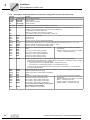
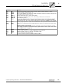
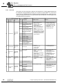
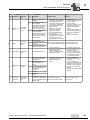
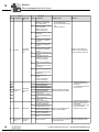
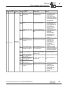
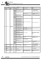
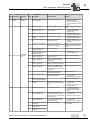
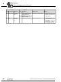
6.2.3
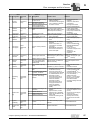
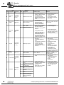
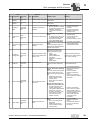
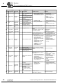
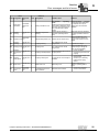
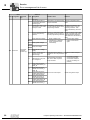
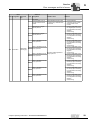
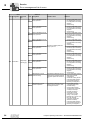
Error list
The factory set error response is listed in the "Response P" column. (P) indicates that
the response is programmable (via P83_error response or with IPOSplus®). In the event
of error 108, (P) indicates that the response can be programmed via P555 DCS error
response In the event of error 109, (P) indicates that the response can be programmed
via P556 DCS alarm response
Error
Suberror
Response
Code Designation
(P)
00
01
03
Code Designation
Possible cause
Measure
0
Output stage
1
VCE monitoring or undervoltage monitoring of the
gate driver
•
•
•
•
•
•
•
5
Inverter remains in hardware current limit
6
VCE monitoring or undervoltage monitoring of the
gate driver or overcurrent
of the current converter.
..Phase U
No error
Overcurrent
Ground fault
Immediate
disconnection
Immediate
disconnection
7
..Phase V
8
..Phase W
Brake chopper
•
•
•
9
..Phase U and V
10
..Phase U and W
11
..Phase V and W
12
..Phase U and V and W
13
Voltage supply
Current converter in status mains operation
14
MFE signal lines
0
Ground fault
0
DC link voltage too high in •
4Q operation
•
1
04
•
Immediate
disconnection
Ground fault
• in the motor lead
• in the inverter
• in the motor
•
•
•
06
Mains phase
failure
Immediate
disconnection
0
Short circuit at output
Motor too large
Defective output stage
Power supply
Current converters
Ramp limit is deactivated
and set ramp time is too
short
Defective phase module
Supply voltage 24 V or 24V
generated from it is instable
Interruption or short circuit
on the signal lines from the
phase modules
DC link voltage periodically too low
•
•
•
•
•
Eliminate ground fault
Consult SEW Service
Too much regenerative
power
Braking resistor circuit
interrupted
Short circuit in the braking
resistor circuit
Brake resistance too high
Brake chopper is defective
•
•
Extend deceleration ramps
Check supply cable to
braking resistor
Check technical data of
braking resistor
Replace MOVIDRIVE® if
the brake chopper is
defective
Phase failure
Inadequate line voltage
quality
•
•
•
•
•
3
07
24
Immediate
DC link overdisconnecvoltage
tion
Check the line cable
Check configuration of the
supply system.
Check supply (fuses,
contactor)
Line frequency fault
4
-
0
DC link voltage too high in DC link voltage too high
2Q operation
•
•
2
DC link voltage too high in
4Q operation ..
.. Phase U
•
3
.. Phase V
4
.. Phase W
1
Rectify the short circuit
Connect a smaller motor
Contact SEW Service for
advice if the output stage
is defective.
Activate P138 and/or
increase ramp time
Extend deceleration ramps
Check supply cable to the
braking resistor
Check technical data of
braking resistor
Compact Operating Instructions – MOVIDRIVE® MDX60B/61B
Service
Error messages and list of errors
Error
Suberror
Response
Code Designation
(P)
08
09
Speed monitoring
Startup
Immediate
disconnection (P)
Immediate
disconnection
Code Designation
Possible cause
Measure
0
Inverter in current limit or
in slip limit
•
•
•
3
"Actual speed" system
limit exceeded.
Speed difference between
ramp setpoint and actual
value for 2×ramp time
•
higher than expected slip.
4
Maximum rotating field
speed exceeded.
•
Maximum rotating field fre•
quency (with VFC max
150 Hz and V/f max 600
•
Hz) exceeded.
0
Startup missing
1
Wrong operating mode
selected
2
Wrong encoder type or
defective encoder card
IPOS-ILLOP
Emergency
stop
0
Invalid IPOS command
Speed controller or current
controller (in VFC operating
mode without encoder)
operating at setting limit due
to mechanical overload or
phase failure in the power
supply or motor.
Encoder not connected
correctly or incorrect
direction of rotation.
nmax is exceeded during
torque control.
In operating mode VFC:
Output frequency ≥ 150 Hz
In operating mode V/f:
Output frequency ≥ 600 Hz
•
•
•
•
•
•
•
Incorrect command
detected during IPOSplus®
program execution.
Incorrect conditions during
command execution.
•
•
•
11
13
Overtempera- Emergency
ture
stop (P)
Control signal source
Immediate
disconnection
0
Heat sink temperature too •
high or temperature sen- •
sor defective
3
Overtemperature
switched-mode power
supply
6
Heat sink temperature too
high or temperature sensor defective.
..Phase U
7
..Phase V
8
..Phase W
(size 7)
0
Thermal overload of inverter •
Temperature sensor of a
•
phase module faulty.
•
(size 7)
Control signal source not
available, e.g. control sig- Control signal source not
nal source fieldbus without defined or defined incorrectly.
fieldbus card
Compact Operating Instructions – MOVIDRIVE® MDX60B/61B
Reduce load
Increase deceleration time
(P501 or P503).
Check encoder
connection, swap A/A and
B/B pairs if necessary
Check encoder voltage
supply
Check current limitation
Extend ramps if necessary
Check motor cable and
motor
Check mains phases
Inverter has not been started up Perform startup for the
for the selected operating mode. required operating mode.
•
10
6
Check the content of the
program memory and, if
necessary, correct.
Load the correct program
into the program memory.
Check program sequence
(→ IPOSplus® manual)
Reduce load and/or
ensure adequate cooling.
Check fan.
If F-11 is issued even
though the temperatures is
obviously not too high, this
indicates a faulty temperature sensor of the phase
module.
Replace the phase module
(Size 7)
Set correct control signal
source (P101).
25
Service
Error messages and list of errors
6
Error
Suberror
Response
Code Designation
(P)
14
Encoder
Immediate
disconnection
Code Designation
Possible cause
0
Encoder not connected,
defective encoder, defective encoder cable
•
25
Encoder error X15 - Speed
•
range exceeded.
Encoder at X15 turns
faster than 6542 rpm.
26
Encoder error X15 - Card
is defective.
Error in the quadrant evaluation.
27
Encoder error – encoder
connection or encoder is
defective
28
Encoder error X15 - Communication error RS485
channel.
29
Encoder error X14 - Communication error RS485
channel.
30
Unknown encoder type at
X14/X15
31
Plausibility check error
Hiperface® X14/X15
Increments have been
lost.
32
Encoder error Hiperface®
X15
Hiperface® encoder at X15
signals error
33
Encoder error Hiperface®
X14
Hiperface® encoder at X14
signals error
34
Encoder error X15
resolver.
Encoder connection or
encoder is defective.
17
0
"Stack overflow" error
18
0
"Stack underflow" error
19
0
Fault "External NMI"
20
0
Fault "Undefined opcode"
21
Immediate
disconnection
0
"Protection fault" error
"Illegal word operand
access" error
23
0
"Illegal instruction access"
error
24
0
"Illegal external bus
access" error
0
25
26
26
EEPROM
External terminal
Rapid stop
Emergency
stop (P)
Encoder cable or shield not
connected correctly
Short circuit/broken encoder
wire
Encoder defective
Check encoder cable and
shield for correct connection,
short circuit and broken wire.
•
•
0
22
System malfunction
•
Measure
Inverter electronics disrupted,
possibly due to effect of EMC.
Read or write error on
EEPROM power section
11
NV memory read error
NV-RAM inside the unit
13
NV memory chip card
System module defective
14
NV memory chip card
Memory card defective
16
NV memory initialization
error
0
External terminal
Check grounding and
shielding and improve, if
necessary.
Consult SEW Service if the
error reoccurs.
•
•
Access to the EEPROM of the
memory card has failed
•
Activate factory settings,
perform reset and reset
parameters.
Contact SEW service if the
error occurs again.
Replace memory card.
Eliminate respective cause;
Read in external error signal via
reprogram terminal if necesprogrammable input.
sary.
Compact Operating Instructions – MOVIDRIVE® MDX60B/61B
Service
Error messages and list of errors
Error
Suberror
Response
Code Designation
(P)
Code Designation
0
27
No limit
switches
Emergency
stop
2
3
Possible cause
Both limit switches missing •
or open circuit
•
Limit switch reversed
Both limit switches are
active simultaneously
Measure
•
Open circuit/both limit
switches missing.
Limit switches are swapped •
over in relation to direction
•
of rotation of motor
Check wiring of limit
switches.
Swap over limit switch
connections.
Reprogram terminals
0
Fault "Fieldbus timeout"
Fieldbus card does not
boot
•
No communication between
master and slave within the pro- •
jected response monitoring.
Check communications
routine of the master
Extend fieldbus timeout
time (P819) or deactivate
monitoring
28
Fieldbus
Timeout
Rapid stop
(P)
2
29
Limit switch
contacted
Emergency
stop
0
Hardware limit switch
approached
A limit switch was reached in
IPOSplus® operating mode.
•
•
Check travel range.
Correct user program.
Emergency
stop
Timeout
Immediate
disconnection
0
30
Time violation stop emergency stop rate
•
•
Drive overloaded
Emergency stop ramp too
short.
•
•
Check configuration
Extend emergency stop
ramp
•
Motor too hot, TF/TH has
triggered
TF/TH of the motor not
connected or connected
incorrectly
MOVIDRIVE® connection
and TF/TH connection on
motor interrupted
•
Let motor cool off and
reset error
Check connections/link
between MOVIDRIVE®
and TF/TH.
If a TF/TH is not
connected: Jumper X10:1
with X10:2.
Set P835 to "No
response".
•
31
TF/TH sensor tripped
None
Response
(P)
0
Thermal motor protection
error
•
•
•
•
32
IPOS index
overflow
Emergency
stop
33
Setpoint
source
Immediate
disconnection
34
Ramp
Timeout
Immediate
disconnection
Programming principles vioCheck and correct the
lated leading to system internal IPOSplus® user program (see
stack overflow
IPOSplus® manual).
0
IPOS program defective
0
Setpoint source not available, e.g. control signal
Setpoint source not defined or
source fieldbus without
defined incorrectly.
fieldbus card
0
Time violation rapid stop
ramp
0
Operating mode not avail- •
able
Wrong assignment operat- •
1
Time of downward ramps
exceeded, e.g. due to overload.
ing mode - hardware
2
35
Operating
mode
Immediate
disconnection
Wrong assignment operating mode - technology
•
function
•
0
36
Option missing
6
Immediate
disconnection
2
Hardware is missing or not •
permitted.
•
Encoder slot error.
3
Fieldbus slot error.
4
Expansion slot error.
•
System
watchdog
Immediate
disconnection
0
37
System software
Immediate
disconnection
0
38
Error "watchdog overflow
system"
Operating mode not defined
or defined incorrectly
P916 was used to set a
ramp function that is needed
by a MOVIDRIVE® unit in
technology version.
P916 was used to set a
ramp type that does not
match the selected
technology function.
P916 was used to set a
ramp type that does not
match the selected
synchronization time
(P888).
Type of option card not
allowed
Setpoint source, control
signal source or operating
mode not permitted for this
option card
Incorrect encoder type set
for DIP11B.
Set correct setpoint source
(P100).
•
•
•
•
•
•
•
•
•
•
•
Extend the downwards
ramps
Eliminate overload
Use P700 or P701 to set
correct operating mode.
Use MOVIDRIVE® in
technology version (..OT).
From the "Startup →
Select technology
function..." menu, select
the technology function
that matches P916.
Check the settings of P916
and P888
Use correct option card
Set correct setpoint source
(P100)
Set correct control signal
source (P101)
Set correct operating
mode (P700 or P701)
Set the correct encoder
type
Error while executing system
software
Consult SEW Service.
System malfunction
Consult SEW Service.
"System software" error
Compact Operating Instructions – MOVIDRIVE® MDX60B/61B
27
Service
Error messages and list of errors
6
Error
Suberror
Response
Code Designation
(P)
39
Reference
travel
Immediate
disconnection (P)
Code Designation
Possible cause
Measure
•
•
•
•
0
"Reference travel" error
•
•
40
41
Immediate
Boot synchrodisconnecnization
tion
Watchdog
option
0
Timeout at boot synchronization with option.
0
Error – Watchdog timer
from/to option.
17
Watchdog IPOS error.
Immediate
disconnection
•
•
•
•
•
•
•
•
42
Lag error
Immediate
disconnection (P)
0
•
Positioning lag error
•
The reference cam is
missing or does not switch
Limit switches are
connected incorrectly
Reference travel type was
changed during reference
travel
Error during boot
synchronization between
inverter and option.
Synchronization ID not/
incorrectly transmitted
Error in communication
between system software
and option software
Watchdog in the IPOSplus®
program
•
Install a new option card if this
error reoccurs.
•
•
Consult SEW Service.
Check IPOS program
•
Check whether the unit
has been activated for the
application version (P079)
Check the selected
technology function (P078)
An application module
without the application
•
version has been loaded in
®
a MOVIDRIVE B unit
The wrong technology
function has been set if an
application module is used
Encoder connected
incorrectly
Acceleration ramps too
short
P component of positioning
controller too small
Incorrectly set speed
controller parameters
Value of lag error tolerance
too small
•
•
•
•
•
•
•
43
44
45
28
RS485Timeout
Rapid stop
(P)
Immediate
Unit utilization disconnection
Initialization
Immediate
disconnection
Check reference cam
Check limit switch
connection
Check reference travel
type setting and required
parameters.
Check encoder connection
Extend ramps
Set P component to higher
value
Reset speed controller
parameters
Increase lag error
tolerance
Check wiring of encoder,
motor and mains phase.
Check whether
mechanical system
components can move
freely or if they are blocked
0
Check RS485 connection (e.g.
Communication timeout at Error during communication via inverter - PC, inverter RS485 interface.
interface RS485
DBG60B). If necessary, contact SEW Service.
0
Unit utilization error
8
UL monitoring error
•
Unit utilization (IxT value) > •
125%
•
•
•
0
General error during initial- •
ization
3
Data bus error during RAM
check
6
CPU clock error.
7
Error in the current evaluation.
10
Error when setting flash
protection
11
Data bus error during RAM
check
12
Parameter setting error
synchronous operation
(internal synchronous
operation)
•
•
No parameters set for
EEPROM in power section,
or parameters set
•
incorrectly.
Option card not in contact
with backplane bus.
Decrease power output
Extend ramps
If suggested actions not
possible, use larger
inverter.
Reduce load
Restore factory settings
Consult SEW Service if the
error still cannot be reset.
Insert the option card
correctly.
Compact Operating Instructions – MOVIDRIVE® MDX60B/61B
Service
Error messages and list of errors
Error
Suberror
Response
Code Designation
(P)
Code Designation
Possible cause
Measure
46
System bus 2 Rapid stop
timeout
(P)
0
Timeout system bus CAN2 Error during communication via
Check system bus connection.
system bus 2.
47
System bus 1 Rapid stop
timeout
(P)
0
Timeout system bus CAN1 Error during communication via
Check system bus connection.
system bus 1.
Immediate
disconnection
Hardware synchronous
operation
0
Only in IPOSplus® operating
•
mode:
•
Invalid control word IPOS • An attempt was made to set
an invalid automatic mode
•
(via external controller).
• P916 = BUS RAMP is set.
IPOS SW limit No response
0
switch
(P)
Software limit switch
reached
Only in IPOSplus® operating
•
mode:
•
Programmed target position is
outside travel range delimited by
software limit switches.
79
Immediate
Hardware
disconnecconfiguration
tion
0
The following items do not
match anymore after having
replaced the memory card:
Deviating hardware config- • Power
uration when replacing the • Rated voltage
• Variant identification
memory card
• Unit series
• Application or standard
version
• Option cards
0
"RAM test" error
80
RAM test
77
78
81
82
Hardware
DRS
•
Only with DRS11B:
• Encoder signal from master/
synchronous encoder faulty.
•
• Hardware required for
•
synchronous operation is
faulty.
0
48
IPOS control
word
None
Response
(P)
Immediate
disconnection
Immediate
Start condition disconnection
Open output
6
Immediate
disconnection
0
0
Start condition error with
VFC hoist
Output open with VFC
hoist
Compact Operating Instructions – MOVIDRIVE® MDX60B/61B
Internal unit fault, RAM defective.
Check encoder signals of
master/synchronous
encoder.
Check encoder wiring.
Replace synchronous
operation card.
Check serial connection to
external control.
Check write values of
external control.
Set correct value for P016.
Check the user program
Check position of the
software limit switches
Ensure identical hardware or
restore factory setting (parameter = factory setting).
Consult SEW Service.
•
Only in "VFC hoist" operating
mode:
The motor could not be supplied •
with the correct amount of current during the pre-magnetizing
•
time:
• Rated motor power too
small in relation to rated
inverter power.
• Motor cable cross section
too small.
Only for operation with a linear motor (as of firmware 18):
• The drive has been set to
•
"Enable" although the
commutation offset between
linear motor and linear
encoder is not known. This
means that the inverter
cannot set the current
indicator correctly.
Only in "VFC hoist" operating •
mode:
• Two or all output phases
•
interrupted.
• Rated motor power too
small in relation to rated
inverter power.
Check startup data and
perform new startup, if
necessary.
Check connection
between inverter and
motor.
Check cross section of
motor cable and increase if
necessary.
Perform commutation
travel in the "No enable"
state and then switch to
"Enable" once the inverter
has acknowledged in
status word bit 25 that
commutation was
successful.
Check connection
between inverter and
motor.
Check startup data and
perform new startup, if
necessary.
29
Service
Error messages and list of errors
6
Error
Suberror
Response
Code Designation
(P)
Code Designation
0
84
86
Immediate
Memory moddisconnecule
tion
2
UL monitoring error
2
Hardware card detection
wrong memory card
0
Technology function
A technology function was actiselected with standard unit
Disable technology function
vated in a standard version.
0
"Flying start" error
Only in VFC n-CTRL operating
Inverter not enabled before
mode:
actual speed is
Actual speed > 6000 rpm with
≤ 6000 rpm.
the inverter enabled.
Stahl WCS3 dirt problem
Encoder signals an error
0
Fault "Absolute encoder"
The encoder signals an error,
e.g. power failure.
• Connection cable between
the encoder and DIP11B
does not meet the
requirements (twisted pair,
shielded).
• Cycle frequency for cable
length too high.
• Permitted max. speed/
acceleration of encoder
exceeded.
• Encoder defective.
0
Power section parameters
5
Control unit data
6
Power section data
7
Invalid version of the configuration data set
Flying start
Immediate
disconnection
92
DIP encoder
problem
Error display
1
(P)
95
EEPROM
checksum
Immediate
shut-off
DIP plausibil- Emergency
ity error
stop (P)
97
Copy error
Immediate
disconnection
98
CRC error
Immediate
disconnection
•
•
No thermal motor model
available
Reduce load.
Extend ramps.
Observe longer pause
times.
Check P345/346
Select a larger motor
Error in connection with
memory module
88
94
Motor utilization too high.
•
IN-UL monitoring 1 triggered •
P530 set later to "KTY"
•
4
Immediate
disconnection
Emergency
stop (P)
Measure
0
Technology
function
DIP encoder
error
"Motor temperature simu- •
lation" error
•
Short circuit or open circuit •
in the temperature sensor
3
87
93
30
Motor protec- Emergency
tion
stop (P)
Possible cause
0
Validity check of absolute
position
•
•
No plausible position could be
determined.
• Incorrect encoder type set.
• IPOSplus® travel parameter
set incorrectly.
• Numerator/denominator
factor set incorrectly.
• Zero adjustment performed.
• Encoder defective.
•
•
2
Not possible to adopt
parameters.
Not possible to adopt
parameters from memory
card.
0
"CRC via internal flash"
error
Tighten knurled screw
Insert and secure memory
card
Replace memory card
Possible cause: Encoder is
dirty → clean encoder
•
•
•
•
•
Check absolute encoder
connection.
Check connection cables.
Set correct cycle
frequency.
Reduce maximum
traveling velocity or ramp.
Replace the absolute
encoder.
Inverter electronics disrupted,
possibly due to effect of EMC or Send unit in for repair.
a defect.
Parameter set upload is/
was faulty
Download of parameter
set to unit cancelled.
•
•
•
0
1
No memory card
Memory card defective
Memory card cannot be
written or read.
Error during data
transmission
Internal unit error
Flash memory defective
•
•
•
•
•
•
•
•
Set the correct encoder
type.
Check IPOSplus® travel
parameters.
Check traveling velocity.
Correct numerator/
denominator factor.
After zero adjustment
reset.
Replace the absolute
encoder.
Repeat copying process
Restore default setting
(P802) and repeat copying
process
Send unit in for repair.
Compact Operating Instructions – MOVIDRIVE® MDX60B/61B
Service
Error messages and list of errors
Error
6
Suberror
Response
Code Designation
(P)
Code Designation
Possible cause
plus®
Measure
"Ramp calculation" error
Only in IPOS
operating
mode:
Positioning ramp is sinusoidal or
square and an attempt is made
to change ramp times and traveling velocities with enabled
inverter.
Rewrite the IPOSplus® program
so that ramp times and traveling velocities can only be
altered when the inverter is
inhibited.
Vibrations diagnostics
warning
Vibration sensor warning (→
"DUV10A" operating instructions).
Determine cause of vibrations.
Continue operation until F101
occurs.
99
IPOS ramp
calculation
Immediate
disconnection
100
Vibration
warning
Display error
0
(P)
101
Rapid stop
Vibration error
(P)
102
Oil aging
warning
Display error
0
(P)
Oil aging warning
Error message from the oil
aging sensor
Schedule oil change.
103
Oil aging error
Display error
0
(P)
Oil aging error
Error message from the oil
aging sensor
SEW-EURODRIVE recommends that you change the
gear unit oil immediately.
104
Oil aging
Display error
overtempera0
(P)
ture
Oil aging overtemperature
•
Overtemperature signal from the
•
oil aging sensor
Let oil cool down
Check if the gear unit cools
properly
•
Check voltage supply of oil
aging sensor
Check and, if necessary,
replace the oil aging
sensor
0
0
Vibration diagnostics error Vibration sensor reports error.
SEW-EURODRIVE recommends that you remedy the
cause of the vibrations immediately
105
Oil aging
ready signal
Display error
0
(P)
Oil aging ready signal
Oil aging sensor is not ready for
•
operation
106
Brake wear
Display error
0
(P)
Brake wear error
Brake lining worn
107
Line components
Immediate
disconnection
No feedback signal from
main contactor.
Defective main contactor
1
Compact Operating Instructions – MOVIDRIVE® MDX60B/61B
Replace brake lining (→
"Motors" operating instructions).
•
•
Check main contactor
Check control cables.
31
Service
Error messages and list of errors
6
Error
Suberror
Response
Code Designation
(P)
Code Designation
Possible cause
0
DCS error
1
Error during transfer of
configuration data to the
monitoring unit.
2
Measure
Interruption in connection during Send the configuration files
program download
again
Configuration data for soft- Subassembly configured with
Configure subassembly with
ware version of the subas- incorrect software version of the permitted version of the prosembly is invalid.
programming interface.
gramming interface. Then
switch subassembly off and on
again.
3
Unit was programmed with Program or configuration data Check the design of the subasincorrect programming
was loaded into the unit with an sembly. Configure again with a
interface.
incorrect programming interface. valid programming interface.
Then switch the unit off and on
again.
4
Faulty reference voltage.
5
6
Faulty system voltage.
•
•
Supply voltage of the
subassembly is defective.
Faulty component in the
subassembly
•
•
Check supply voltage
Switch unit off and on
again
7
8
9
108
32
DCS error
Immediate
stop/malfunction (P)
Faulty test voltage
10
Faulty DC 24 V voltage
supply
11
Ambient temperature of
the unit is not in the
defined range.
Temperature at the place of
Check the ambient temperaoperation is not in the permitted ture.
range.
12
Plausibility error for position changeover
For the position changeover,
ZSC, JSS or DMC is permanently activated.
13
Faulty switching of the
LOSIDE driver DO02_P /
DO02_M
14
Faulty switching of the
HISIDE driver DO02_P /
DO02_M
15
Faulty switching of the
LOSIDE driver DO0_M
16
Faulty switching of the
HISIDE driver DO0_P
17
Faulty switching of the
LOSIDE driver DO01_M
18
Faulty switching of the
HISIDE driver DO01_P
Short circuit of the output.
•
•
•
Check ZSC activation
Check JSS activation
Check DMC activation
(only for monitoring via
position)
Check wiring at the output.
Compact Operating Instructions – MOVIDRIVE® MDX60B/61B
Service
Error messages and list of errors
Error
Suberror
Response
Code Designation
(P)
Code Designation
0
DCS alarm
1
Communication error at
the CAN interface of the
inverter
2
3
Possible cause
Measure
The DCS21B/31B option does
not receive any valid data from
the inverter.
•
Plausibility error digital
input at pulse P1
•
•
•
4
5
Plausibility error digital
input at pulse P2
•
•
6
7
Pulse 1 plausibility error at
binary input DI3
•
•
8
109
DCS alarm
6
Rapid stop/
warning (P)
9
10
11
Pulse 1 plausibility error at
binary input DI4
•
No pulse1 voltage present at
Pulse 1 plausibility error at binary input DI1
binary input DI5
•
•
•
12
13
Pulse 1 plausibility error at
binary input DI6
•
•
14
15
Pulse 1 plausibility error at
binary input DI7
•
•
16
17
Pulse 1 plausibility error at
binary input DI8
•
•
Compact Operating Instructions – MOVIDRIVE® MDX60B/61B
Check hardware
connection to the inverter
Check version of the
inverter
Check configuration of the
DI1 digital input according
to configuration and wiring
diagram
Check wiring
Check configuration of the
DI2 binary input according
to configuration and wiring
diagram
Check wiring
Check configuration of the
DI3 binary input according
to configuration and wiring
diagram
Check wiring
Check configuration of the
DI4 binary input according
to configuration and wiring
diagram
Check wiring
Check configuration of the
DI5 binary input according
to configuration and wiring
diagram
Check wiring
Check configuration of the
DI6 binary input according
to configuration and wiring
diagram
Check wiring
Check configuration of the
DI7 binary input according
to configuration and wiring
diagram
Check wiring
Check configuration of the
DI8 binary input according
to configuration and wiring
diagram
Check wiring
33
Service
Error messages and list of errors
6
Error
Suberror
Response
Code Designation
(P)
Code Designation
18
19
Possible cause
Measure
•
Pulse 2 plausibility error at
binary input DI1
•
20
21
Pulse 2 plausibility error at
binary input DI2
•
•
22
23
Pulse 2 plausibility error at
binary input DI3
•
•
24
25
26
27
Pulse 2 plausibility error at
binary input DI4
•
No pulse 2 voltage present at
Pulse 2 plausibility error at binary input DI1.
binary input DI5
•
•
•
28
29
Pulse 2 plausibility error at
binary input DI6
•
•
109
DCS alarm
Rapid stop/
warning (P)
30
31
Pulse 2 plausibility error at
binary input DI7
•
•
32
33
Pulse 2 plausibility error at
binary input DI8
•
•
34
35
36
37
Check configuration of the
DI2 binary input according
to configuration and wiring
diagram
Check wiring
Check configuration of the
DI3 binary input according
to configuration and wiring
diagram
Check wiring
Check configuration of the
DI4 binary input according
to configuration and wiring
diagram
Check wiring
Check configuration of the
DI5 binary input according
to configuration and wiring
diagram
Check wiring
Check configuration of the
DI6 binary input according
to configuration and wiring
diagram
Check wiring
Check configuration of the
DI7 binary input according
to configuration and wiring
diagram
Check wiring
Check configuration of the
DI8 binary input according
to configuration and wiring
diagram
Check wiring
Plausibility error in the
speed recording
The difference between the two •
speed sensors is higher than the
configured speed cut-off thresh•
old.
•
Check track again with the
data of the encoder
configuration.
Check the velocity sensor
Use the SCOPE function
to set speed signals so
that they are congruent
Plausibility error in the
position acquisition
The difference between the two •
position sensors is higher than
the configured value.
•
•
Check track with the
configured data of the
encoder setting
Check position signal
Are all signals connected
correctly to the 9-pin
encoder connector?
Check the encoder
connector for correct
wiring. Is the jumper
between pin 1 and pin 2 on
the 9-pin encoder
connector closed (SSI
absolute encoder)?
Use the SCOPE function
to set positions signals so
that they are congruent
•
•
34
Check configuration of the
DI1 digital input according
to configuration and wiring
diagram
Check wiring
Compact Operating Instructions – MOVIDRIVE® MDX60B/61B
Service
Error messages and list of errors
Error
Suberror
Response
Code Designation
(P)
Code Designation
Possible cause
Measure
38
The current position is outside
the configured range.
•
39
Plausibility error incorrect
position range
•
•
40
41
Plausibility error incorrect
speed.
The current speed exceeds the •
configured maximum speed.
•
•
42
43
Configuration error: Accel- The current acceleration is out- •
eration
side the configured acceleration
range.
•
•
•
44
45
109
DCS alarm
6
Rapid stop/
warning (P)
The wiring of the encoder does •
Plausibility error in
encoder interface (A3401 not correspond to the configured
= encoder 1 and A3402 = data.
•
encoder 2).
•
•
46
47
Encoder supply voltage
error (A3403 = encoder 1
and A3404 = encoder 2)
48
49
Reference voltage error
50
Difference level RS485
driver 1 (error INC_B or
SSI_CLK) faulty
51
52
53
54
55
56
57
Difference level RS485
driver 2 (error INC_A or
SSI_DATA) faulty.
Encoder voltage supply is out- •
side the defined range (min. DC
20 V / max. DC 29 V).
•
Check track with the
configured data of the
encoder setting
Check position signal,
correct offset if necessary
Use the SCOPE function
to read off the position and
set in ratio to the
configured values
The drive moves outside
the permitted and
configured speed range
Check configuration (set
max. velocity)
Analyze the speed
development using the
SCOPE function
Check encoder type and
configuration (SSI/
incremental)
Check the encoder
connection/wiring
Check polarity of the
encoder data
Check function of the
encoder
Check encoder type and
configuration (SSI/
incremental)
Check the encoder
connection/wiring
Check polarity of the
encoder data
Check function of the
encoder
Overload in the supply
voltage of the encoder;
internal fuse has triggered
Check supply voltage of
the DCS21B/31B option
The reference voltage input of
the encoder system is outside
the defined range.
Check reference voltage input
of the encoder system.
No encoder connection, incorrect encoder type.
Check the encoder connection.
Incremental counter deviation
The wiring of the encoder does •
Plausibility error in
encoder interface (A3401 not correspond to the configured
= encoder 1 and A3402 = data.
•
encoder 2)
•
•
Compact Operating Instructions – MOVIDRIVE® MDX60B/61B
Check encoder type and
configuration (SSI/
incremental)
Check the encoder
connection/wiring
Check polarity of the
encoder data
Check function of the
encoder
35
Service
Error messages and list of errors
6
Error
Suberror
Response
Code Designation
(P)
Code Designation
58
59
Possible cause
Measure
Plausibility error SIN/COS Incorrect encoder type conencoder connection.
nected.
•
•
Check encoder connection
Check the encoder
connection (jumper
between pin 1 and pin2)
Plausibility error incremenPhase error of the incremental
tal encoder connection
or sin/cos encoder.
•
•
Check encoder connection
Replace the defective
encoder
Connected encoder type does •
not correspond to the configura- •
tion.
Check encoder connection
Check connected encoder
60
61
62
63
64
65
66
67
109
DCS alarm
Rapid stop/
warning (P)
Plausibility error - SSI
encoder connection.
Plausibility error - SSI listener encoder connection
68
Faulty switching of the
LOSIDE driver DO2_M
69
Faulty switching of the
HISIDE driver DO2_P
70
Faulty switching of the
LOSIDE driver DO0_M
71
Faulty switching of the
HISIDE driver DO0_P
72
Faulty switching of the
LOSIDE driver DO1_M
73
Faulty switching of the
HISIDE driver DO1_P
74
Undervoltage test watchdog for LOSIDE driver
DC 0 V short circuit at on of the
DC 0 V outputs.
75
Undervoltage test watchdog for HISIDE driver
DC 24 V short circuit at on of the
DC 24 V outputs.
76
CCW and CW monitoring
(in DMC module) activated
simultaneously
77
78
79
80
81
82
83
84
DC 0 V short circuit at the output.
CCW and CW monitoring
range of the OLC activated Multiple activation.
simultaneously
Check wiring at the outputs.
Only one direction of rotation
can be activated in the DMC
module.
CCW and CW monitoring
(in JSS module) was activated simultaneously
Input element with time monitor- •
Timeout error MET.
Time monitoring start sig- ing is faulty.
•
nal for confirmation button.
85
Timeout error MEZ.
Time monitoring for twohand button.
86
EMU1 monitoring error
•
EMU2 monitoring error
Faulty monitoring of the external
•
disconnection channel
87
88
•
•
•
Check hardware
connections
Pick-up or release time too
short
Check switching contacts
Check configuration
Shorten duration of
operation below 5 Hz
110
"Ex-e protec- Emergency
tion" error
stop
113
Analog input
open circuit
No response
0
(P)
AI1 analog input open cirAI1 analog input open circuit
cuit
Check wiring
116
"Timeout
MOVI-PLC"
error
Rapid stop/
warning
MOVI-PLC® communication timeout
•
•
Positioning
interruption
Emergency
stop (P)
123
0
0
0
Duration of operation
below 5 Hz exceeded
Check wiring of input
element
Input element faulty
Two-hand operation with time
monitoring is faulty.
89
36
Check wiring at the output.
Error "Positioning/Positioning interruption"
Duration of operation below 5
Hz exceeded
Check startup
Check wiring
Perform positioning process
Target monitoring when interwithout interruption until it is
rupted positioning process is
resumed. Target would be over- complete.
run.
Compact Operating Instructions – MOVIDRIVE® MDX60B/61B
Service
Error messages and list of errors
Error
Suberror
Response
Code Designation
(P)
Code Designation
124
1
Ambient con- Emergency
ditions
stop (P)
Possible cause
Permitted ambient temper- Ambient temperature > 60°C
ature exceeded
Measure
•
•
196
Immediate
Power section disconnection
6
Improve ventilation and
cooling conditions
Improve air supply to the
control cabinet; check filter
mats.
1
Discharge resistor
Discharge resistor overload
Observe waiting time for power
on/off
2
Hardware ID precharge/
discharge control
Incorrect precharge/discharge
control variant
•
•
Consult SEW Service
Replace precharge/discharge control
3
Inverter coupling PLD Live Defective inverter coupling
•
•
Consult SEW Service
Replace inverter coupling
4
Inverter coupling reference Defective inverter coupling
voltage
•
•
Consult SEW Service
Replace inverter coupling
5
Power section configuration
Different phase modules
installed in the unit
•
•
Inform SEW service.
Check and replace phase
modules
6
Control unit configuration
Control unit line inverter or
motor inverter incorrect
Replace or correctly assign the
control unit of line and motor
inverter.
7
Communication power
section control unit
No communication
Check control unit installation.
8
Communication precharge/discharge control
inverter coupling
No communication
•
•
10
Communication power
section control unit
The inverter coupling does not
support protocol
Replace inverter coupling
11
Communication power
section control unit
Faulty communication with
inverter coupling at power-up
(CRC error).
Replace inverter coupling
12
Communication power
section control unit
Inverter coupling uses protocol Replace inverter coupling
that does not match control unit
13
Communication power
section control unit
Replace inverter coupling
Faulty communication with
inverter coupling during operation: More than once per second
a CRC error.
14
Control unit configuration
Missing PLD functionality for
EEPROM data set size 7.
15
Inverter coupling error
Inverter coupling processor has •
signaled internal error.
•
16
Inverter coupling error:
PLD version incompatible
17
Precharge/discharge con- Precharge/discharge control
•
trol error
processor has signaled internal
error
•
Consult SEW service if the
error reoccurs
Replace precharge/discharge control
18
Defective DC link fan
The DC link fan is faulty.
Consult SEW Service
Check whether DC link
choke fan is connected or
faulty
19
Communication power
section control unit
Faulty communication with
•
inverter coupling during operation: More than once per second •
an internal error.
Consult SEW Service if the
error reoccurs.
Replace inverter coupling
20
Communication power
section control unit
The control unit has not sent
any messages to the inverter
coupling for a while.
Consult SEW Service if the
error reoccurs.
Replace inverter coupling
21
Uz measurement implausi- Defective phase module
ble phase R
22
Uz measurement implausible phase S
23
Uz measurement implausible phase T
Compact Operating Instructions – MOVIDRIVE® MDX60B/61B
Check wiring
Consult SEW Service
Replace control unit
Consult SEW service if the
error reoccurs
Replace inverter coupling
Replace inverter coupling
•
•
•
•
Consult SEW service if the
error reoccurs
37
Service
Error messages and list of errors
6
Error
Suberror
Response
Code Designation
(P)
Code Designation
197
1
Line overvoltage (motor
Inadequate line voltage quality.
inverter only at start of precharging process)
2
Line undervoltage (only
with line inverter)
4
Precharging was aborted
199
Power supply Immediate
disconnection
DC link charg- Immediate
ing
disconnection
Possible cause
Unable to charge DC link.
Measure
•
•
•
•
•
38
Check supply (fuses, contactor)
Check configuration of the
supply system
Precontrol overload
Connected DC link capacity too high
Short circuit in the DC link;
check DC link connection
in case of several units.
Compact Operating Instructions – MOVIDRIVE® MDX60B/61B
Service
SEW electronics service
6.3
SEW electronics service
6.3.1
Send in for repair
6
Please contact the SEW-EURODRIVE electronics service if an error cannot be rectified (→ "Customer and spare parts service").
When contacting SEW electronics service, always quote the digits on the status label so
that our service personnel can assist you more effectively.
Provide the following information when sending the unit in for repair:
6.4
•
Serial number (→ nameplate)
•
Unit designation
•
Standard version or application version
•
Digits on the status label
•
Short description of application (drive application, control via terminals or serial)
•
Connected motor (motor type, motor voltage, connection 댴 or 쑶)
•
Nature of the fault
•
Accompanying circumstances
•
Your own presumptions as to what has happened
•
Any unusual events preceding the problem, etc.
Extended storage
If the unit is stored for a long time, connect it to the mains voltage for at least 5 minutes
every 2 years. Otherwise, the unit's service life may be reduced.
Procedure when maintenance has been neglected:
Electrolytic capacitors are used in the inverters. They are subject to aging effects when
deenergized. This effect can damage the capacitors if the unit is connected using the
rated voltage after a longer period of storage.
If you have not performed maintenance regularly, SEW-EURODRIVE recommends that
you increase the line voltage slowly up to the maximum voltage. This can be done, for
example, by using a variable transformer for which the output voltage has been set according to the following overview.
Compact Operating Instructions – MOVIDRIVE® MDX60B/61B
39
Service
Disposal
6
The following stages are recommended:
AC 400/500 V units:
•
Stage 1: AC 0 V to AC 350 V within a few seconds
•
Stage 2: AC 350 V for 15 minutes
•
Stage 3: AC 420 V for 15 minutes
•
Stage 4: AC 500 V for 1 hour
AC 230 V units:
•
Stage 1: AC 170 V for 15 minutes
•
Stage 2: AC 200 V for 15 minutes
•
Stage 3: AC 240 V for 1 hour
After you have completed the regeneration process, the unit can be used immediately
or stored again for an extended period with maintenance.
6.5
Disposal
Please follow the current instructions. Dispose in accordance with the material structure
and the regulations in force for instance as:
40
•
Electronics scrap (circuit boards)
•
Plastic (housing)
•
Sheet metal
•
copper
Compact Operating Instructions – MOVIDRIVE® MDX60B/61B
Declarations of Conformity
MOVIDRIVE®
7
Declarations of Conformity
7.1
MOVIDRIVE®
7
EC Declaration of Conformity
6(:(852'5,9(*PE+&R.*
(UQVW%OLFNOH6WUDH'%UXFKVDO
GHFODUHVXQGHUVROHUHVSRQVLELOLW\WKDWWKH
IUHTXHQF\LQYHUWHUVRIWKHVHULHV
029,'5,9(%
DUHLQFRQIRUPLW\ZLWK
0DFKLQHU\'LUHFWLYH
(&
/RZ9ROWDJH'LUHFWLYH
(&
(0&'LUHFWLYH
(&
DSSOLHGKDUPRQL]HGVWDQGDUGV
(1
(1
(1
7KHVHSURGXFWVDUHLQWHQGHGIRULQVWDOODWLRQLQPDFKLQHV6WDUWXSLVSURKLELWHGXQWLOLWKDVEHHQ
HVWDEOLVKHGWKDWWKHPDFKLQHU\LQWRZKLFKWKHVHSURGXFWVDUHWREHLQFRUSRUDWHGFRPSOLHVZLWKWKH
SURYLVLRQVRIWKHDIRUHPHQWLRQHG0DFKLQHU\'LUHFWLYH
$FFRUGLQJWRWKH(0&'LUHFWLYHWKHOLVWHGSURGXFWVDUHQRWLQGHSHQGHQWO\RSHUDEOHSURGXFWV(0&
DVVHVVPHQWLVRQO\SRVVLEOHDIWHUWKHVHSURGXFWVKDYHEHHQLQWHJUDWHGLQDQRYHUDOOV\VWHP7KH
DVVHVVPHQWZDVYHULILHGIRUDW\SLFDOV\VWHPFRQVWHOODWLRQEXWQRWIRUWKHLQGLYLGXDOSURGXFW
$OOVDIHW\UHOHYDQWUHTXLUHPHQWVRIWKHSURGXFWVSHFLILFGRFXPHQWDWLRQRSHUDWLQJLQVWUXFWLRQV
PDQXDOHWFPXVWEHPHWRYHUWKHHQWLUHSURGXFWOLIHF\FOH
Bruchsal
Place
Date
Johann Soder
Managing Director Technology
a) b)
a) Authorized representative for issuing this declaration on behalf of the manufacturer
b) Authorized representative for compiling the technical documents
Compact Operating Instructions – MOVIDRIVE® MDX60B/61B
41
Declarations of Conformity
MOVIDRIVE® with DFS11B/DFS21B
7
7.2
MOVIDRIVE® with DFS11B/DFS21B
EC Declaration of Conformity
6(:(852'5,9(*PE+&R.*
(UQVW%OLFNOH6WUDH'%UXFKVDO
GHFODUHVXQGHUVROHUHVSRQVLELOLW\WKDWWKH
IUHTXHQF\LQYHUWHUVRIWKHVHULHV
029,'5,9(%
ZLWKEXLOWLQ
')6%
')6%
352),VDIH
352),VDIH
0DFKLQHU\'LUHFWLYH
(&
/RZ9ROWDJH'LUHFWLYH
(&
(0&'LUHFWLYH
(&
DSSOLHGKDUPRQL]HGVWDQGDUGV
(1
(1
(1
(1
DUHLQFRQIRUPLW\ZLWK
7KHVHSURGXFWVDUHLQWHQGHGIRULQVWDOODWLRQLQPDFKLQHV6WDUWXSLVSURKLELWHGXQWLOLWKDVEHHQ
HVWDEOLVKHGWKDWWKHPDFKLQHU\LQWRZKLFKWKHVHSURGXFWVDUHWREHLQFRUSRUDWHGFRPSOLHVZLWKWKH
SURYLVLRQVRIWKHDIRUHPHQWLRQHG0DFKLQHU\'LUHFWLYH
$FFRUGLQJWRWKH(0&'LUHFWLYHWKHOLVWHGSURGXFWVDUHQRWLQGHSHQGHQWO\RSHUDEOHSURGXFWV(0&
DVVHVVPHQWLVRQO\SRVVLEOHDIWHUWKHVHSURGXFWVKDYHEHHQLQWHJUDWHGLQDQRYHUDOOV\VWHP7KH
DVVHVVPHQWZDVYHULILHGIRUDW\SLFDOV\VWHPFRQVWHOODWLRQEXWQRWIRUWKHLQGLYLGXDOSURGXFW
$OOVDIHW\UHOHYDQWUHTXLUHPHQWVRIWKHSURGXFWVSHFLILFGRFXPHQWDWLRQRSHUDWLQJLQVWUXFWLRQV
PDQXDOHWFPXVWEHPHWRYHUWKHHQWLUHSURGXFWOLIHF\FOH
Bruchsal
Place
Date
Johann Soder
Managing Director Technology
a) b)
a) Authorized representative for issuing this declaration on behalf of the manufacturer
b) Authorized representative for compiling the technical documents
42
Compact Operating Instructions – MOVIDRIVE® MDX60B/61B
Declarations of Conformity
MOVIDRIVE® with DCS21B/DCS31B
7.3
7
MOVIDRIVE® with DCS21B/DCS31B
EC Declaration of Conformity
6(:(852'5,9(*PE+&R.*
(UQVW%OLFNOH6WUDH'%UXFKVDO
GHFODUHVXQGHUVROHUHVSRQVLELOLW\WKDWWKH
IUHTXHQF\LQYHUWHUVRIWKHVHULHV
029,'5,9(%
ZLWKEXLOWLQ
'&6%
'&6%
352),VDIH
0DFKLQHU\'LUHFWLYH
(&
/RZ9ROWDJH'LUHFWLYH
(&
(0&'LUHFWLYH
(&
DSSOLHGKDUPRQL]HGVWDQGDUGV
(1
(1
(1
DUHLQFRQIRUPLW\ZLWK
7KHVHSURGXFWVDUHLQWHQGHGIRULQVWDOODWLRQLQPDFKLQHV6WDUWXSLVSURKLELWHGXQWLOLWKDVEHHQ
HVWDEOLVKHGWKDWWKHPDFKLQHU\LQWRZKLFKWKHVHSURGXFWVDUHWREHLQFRUSRUDWHGFRPSOLHVZLWKWKH
SURYLVLRQVRIWKHDIRUHPHQWLRQHG0DFKLQHU\'LUHFWLYH
$FFRUGLQJWRWKH(0&'LUHFWLYHWKHOLVWHGSURGXFWVDUHQRWLQGHSHQGHQWO\RSHUDEOHSURGXFWV(0&
DVVHVVPHQWLVRQO\SRVVLEOHDIWHUWKHVHSURGXFWVKDYHEHHQLQWHJUDWHGLQDQRYHUDOOV\VWHP7KH
DVVHVVPHQWZDVYHULILHGIRUDW\SLFDOV\VWHPFRQVWHOODWLRQEXWQRWIRUWKHLQGLYLGXDOSURGXFW
$OOVDIHW\UHOHYDQWUHTXLUHPHQWVRIWKHSURGXFWVSHFLILFGRFXPHQWDWLRQRSHUDWLQJLQVWUXFWLRQV
PDQXDOHWFPXVWEHPHWRYHUWKHHQWLUHSURGXFWOLIHF\FOH
Bruchsal
Place
Date
Johann Soder
Managing Director Technology
a) b)
a) Authorized representative for issuing this declaration on behalf of the manufacturer
b) Authorized representative for compiling the technical documents
Compact Operating Instructions – MOVIDRIVE® MDX60B/61B
43
SEW-EURODRIVE—Driving the world
SEW-EURODRIVE
Driving the world
SEW-EURODRIVE GmbH & Co KG
P.O. Box 3023
D-76642 Bruchsal/Germany
Phone +49 7251 75-0
Fax +49 7251 75-1970
[email protected]
www.sew-eurodrive.com