1
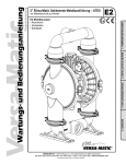
Operating Instructions
General Safety Instructions
Application
Electrical Connection
Installation
Maintenance
Submersible sump pump
You have bought a Jung Pumpen product and
therefore purchased quality and performance.
Guarantee this achievement by an installation
according to the operating instructions so that our
product can meet your demands to your full
satisfaction. Please note that damages as a result
of poor installation will affect the guarantee.
For this reason please follow the advice of the
operating instructions.
Like any other electrical appliance the operation of
this product can fail by electrical failure or
technical faults. It is wise to always consider
standby pumps, emergency generator and a
control unit fitted with mains independent alarm.
U 3 K NIRO
U 3 KS NIRO
U 3 KS NIRO
ID-No. 00205 / 02
ID-No. 00206 / 02
ID-No. 09808 / 02
27610-2.3 0405 page 1
Operating Instructions
General Safety Instruction
Safety instructions relevant for operation
This operation manual gives basic instructions that should
be followed carefully during installation, operation and
maintenance. It is essential that this manual is carefully
read by the responsible personnel/operator before
assembly and commissioning. It is always to be kept
available at the installation site.
If hot or cold machine components involve hazards, they
must be guarded against accidental contact.
Guards for moving parts (e.g. coupling) must not be
removed form the machine while in operation.
Any leakage of hazardous (e.g. explosive, toxic, hot) fluids
(e.g. from the shaft seal) must be drained away so as to
prevent any risk to persons or the environment. Statutory
regulations are to be complied with. The pumping station
must be kept tidy and in good condition.
Hazards resulting from electricity are to be prevented
(see for example, the national-specifications or the
regulations of your local electricity supply company.)
Identification of safety instructions in the
operating manual
Safety instructions given in this manual non-available with
which would affect safety are identified by the following
symbol:
Safety instructions relevant for maintenance,
inspections and assembly work
General danger for personnel
Dangerous voltage
Danger for machine and function
It is imperative that signs affixed to the machine, e.g.
rotation arrow
fluid connection symbols
data / approval plate
be observed and kept legible.
Qualification of personnel
An authorized (certified) electrician and mechanic shall
carry out all work. Scope of responsibility and supervision
of the personnel must be exactly defined by the plant
operator. If the staff does not have the necessary
knowledge, they must be trained and instructed, which
may be performed by the machine manufacturer or
supplier on behalf of the plant operator, moreover, the
plant operator is to make sure that the contents of the
operating manual are fully understood by the personnel.
Hazards in the event of non-compliance with
the safety instructions
Non-compliance with the safety instructions may produce
a risk to the personnel as well as to the environment and
the machine and results in a loss of any right to claim
damages or compensation. For example, non-compliance
may involve the following hazards:
- Failure of important functions of the machine/plant
- Failure of specified procedures of maintenance and
repair
- Exposure of people to electrical, mechanical and
chemical hazards
- Endangering the environment owing to hazardous
substances being released.
Safety regulations for owner / operator
All safety instructions contained in this manual, all relevant
national and local health and safety codes and any other
service and safety instructions issued by the plant operator
shall be complied with.
page 2
It shall be the plant operator’s responsibility to ensure that
all maintenance, inspection and assembly work is
performed by authorized and qualified personnel who have
adequately familiarized themselves with the subject matter
by studying this manual in detail.
Any work on the machine shall only be performed when it
is at a stand-still, it being imperative that the procedure for
shutting down the machine described in this manual be
followed.
Pumps and pump units which convey hazardous media
must be decontaminated. All waste emissions such as
used oil must be appropriately disposed of, oil spills must
be cleaned up and emissions to the environment must be
reported. On completion of work all safety and protective
facilities must be reinstalled and made operative again.
Prior to restarting the machine, the instructions listed under
"Electrical Connection" and "Installation" are to be
observed.
Unauthorized alterations and production of
spare parts
Any modification may be made to the machine only after
consultation with the manufacturer. Using spare parts and
accessories authorised by the manufacturer is in the
interest of safety. Use of other parts may exempt the
manufacturer from any warranty or compensation claims.
Unauthorized modes of operation
The reliability of the machine delivered will be only
guaranteed if it is used in the manner intended, in
accordance with clause 1; of this manual: The limit
values specified in the data sheet must under no
circumstances be exceeded.
Warranty claim
Jung Pumpen pumps are long living, high quality
products with expected reliable operation. However,
should the need arise for a warranty claim, please
contact your Jung Pumpen distributor.
Operating Instructions
List of contents
• General safety instructions............................................................................
page 2
• List of contents..............................................................................................
page 3
• Extent of delivery..........................................................................................
- Application
- Wiring diagram
page 4
• Safety precautions .......................................................................................
page 5
• Installation ....................................................................................................
- Single unit
- Installation with guide rail system
- Duplex unit
- Mobile operation
- Low level pumping
- Whirl system
- Maintenance
page 6 - 8
• Sectional drawing .........................................................................................
page 9
• Spare parts list .............................................................................................
page 10
page 3
Operating Instructions
Technical Data
Supply voltage
Max. switching frequency
Protective system
Max.water temperature
: 1N/PE x 230 V - 50 Hz
: 30 / h
: IP 68
: 1 -35 °C (60 °C short time)
Power input
Dimensions
Weight
: 320 W
: 220 x 230 x 155 mm (h x ∅)
: approx. 3,5 kg / 4,9 kg
Picture 1: dimensions
Description
This manual applies to a Jung Pumpen submersible
sump pump U 3 K or U 3 KS with vortex impeller and
mounted on level control.
Application
-
-
-
-
The U 3 K/KS pump is designed for usual domestic
waste water. It must not be used for pumping
sewage water from lavatories. In some countries
sumps with a connection to the public sewer are an
explosion hazardous location. For this application
the explosion proof UFK series is necessary, for
further information ask your distributor.
Only Ex-approved pumps may be used at different
operating conditions in explosion hazardous
locations. Please ask the industrial and trade
supervision, the building inspection or the
employer´s liability insurance association for such
an application.
Allowed temperature of pumped medium:
Continuous operation : 35 °C (S1-operation)
Intermittent operation : 60°C (S3-operation 40%),
4 min. operation, 6 min. stand by
The pumps can be used for pumping waste water
from dish washers and washing machines.
If kept dry the pump can be stored down to a
minimum temperature of -20°C.
The flooded pump must not freeze.
Without any additional accessories, a low level
pumping in flooded basements, on flat roofs etc.
down to 5 mm water level is possible
(see low level pumping).
Picture 2: wiring diagram
Transportation and storage
The pump can be transported and stored in vertical or
horizontal position.
Always use the handle to carry the pump,
never lift it at the cable. Make sure the pump
cannot roll or fall over and injure people or
damage property.
If kept dry the pump can be stored down to a minimum
temperature of -20°C. The flooded pump must not
freeze.
For longer periods of storage, the pump must be protected
against moisture and heat. The impeller should be rotated
occasionally to prevent the seals from sticking together.
After a long period of storage, the pump should be
inspected before it is taken into operation. Pay special
attention to the seals and the cable gland.
Follow the instructions of „Operation“.
page 4
Do not put the plug into water!
Irruption of water may cause malfunctions.
Because of the built-in thermostat an additional
motor protection is not necessary. Inadmissible high
temperatures and operation times will release the
thermostat. If so, pull out the plug before repairs to
prevent automatically pump restarts.
Operating Instructions
-
-
Please pay attention to the following
regulations at installing the pump(s) or ask
your qualified electrician / distributor.
regulations for electrical installations
(in Germany: VDE 0100, VDE 0165)
regulations for prevention of accidents in sewage
technical installations
(in Germany: GUV 7.4, GUV 17.6)
guidelines for explosion protection
(in Germany: GUV 19.8)
electrical installations in explosion hazardous areas
(in Germany: Elex V)
-
-
-
Safety precautions
In order to minimize the risk of accidents in connection
with the service and installation work, the following rules
should be followed:
Never work alone. Use a lifting harness, safety line
and a respirator as required. Do not ignore the risk
of drowning.
Make sure there are no poisonous gases within the
work area.
Check the explosion risk before welding or using
electric hand tools.
Do not ignore health hazards. Observe strict
cleanliness.
Bear in mind the risk of electrical accidents.
Make sure that the lifting equipment is in good
condition.
Provide a suitable barrier around the work area,
e.g. guard rail
Make sure you have a clear path of retreat.
Use safety helmet, safety goggles and protective
shoes.
All personnel who work with sewage systems must
be vaccinated against diseases to which they may
be exposed.
A first-aid kit must be close at hand.
Note that special rules apply to installation in
explosive atmosphere.
Follow all other health and safety rules and local codes
and ordinances
Electrical connection
Special rules apply to installation in
explosive atmosphere.
Intrinsically safe circuits (Exi) are
normally required for the automatic
level control system by level regulators.
-
A Jung Pumpen control unit gives you the certainty of
design under safety regulations and an acceptance of
work without any problems.
-
Level sensors must be used at low voltage. For
further details please see data sheet / o.m.
Local rules may specify otherwise.
To prevent the pump from blocking after long rest
periods an additional daily trial run unit can be
installed.
Connection only to a mains supply installed in
accordance to the local regulations. For fusing of
d.o.l. starting pumps use only 10 A slow fuses or
automatic circuit-breaker with C or D characteristic.
(former G and K)
Because the motor´s nominal voltage is measured
at the terminal board of the pump, please consider
the voltage drop of long supply cables.
The motors of the three-phase a.c. pumps must be
protected by a suitable overcurrent release.
Adjustment as following:
direct start:
+ 10% of the nominal current
star-delta start:
(nominal current x 0,58) + 10 %
If the protective arrangement has trigged, eliminate
the trouble
Replace the cable if the cable jacket is damaged.
Do not pinch the cable or pull it around sharp
bends.
Always install the control unit in a dry and well
ventilated room above the backpressure level.
Never install the control unit in the sump !
-
-
-
-
Following works should only be done by
qualified and authorized electricians.
- Jung Pumpen disclaims all responsibility
for work done by untrained or/and
unauthorized personnel.
- Heed operating voltage !
(see name plate and additional labels)
Take out the main fuses to isolate the mains supply
from the control unit before repairs or any other
works and make sure it cannot be energized again.
If the pump is equipped with automatic level
control, there is a risk of sudden restart.
Before starting check the efficiency of the
protective arrangements of the pump and the
monitoring equipment. Failure to heed this warning
may cause a lethal accident.
Do not put the lead ends into water!
Irruption of water may cause malfunctions.
-
-
-
-
page 5
If persons are likely to come into physical contact
with pump or pumped media, the earthed
(grounded) socket must have an additional
connection to an earth- (ground) fault protection
device (GFI).
When pumping near a lake, a jetty, a pond etc. a
safety distance of at least 20 m between the
person and the pump is applicable. Do not place
the pump directly in a pool. Observe the special
safety regulations if used in connection with
swimming pools.
Use the pump only in accordance to the data
stated on the pump´s plate resp. in the technical
data on page 4.
-
Earthing
For safety reasons, the earth conductor should be
appr. 50 mm (2 inch) longer than the phase conductors.
If the motor cable is jerked loose by mistake, the earth
conductor should be at last conductor to come loose
from its terminal. This applies to both ends of cable.
Ensure the correct earthing of the pump and the control
unit.
Operating Instructions
Picture 3: single installation example
Installation
To ensure the proper installation, consider the
dimensions of the installation. The sump has to be
cleaned from all sediments before any installation or
repair works. The minimum height between the lifting
hook and the floor shall be sufficient to lift the pump out
of the sump. The lifting equipment shall be able to hoist
the pump straight up and down in the sump, preferably
without the need for resetting the lifting hook. Oversized
lifting equipment could cause damages if the pump
should stick when it is lifted.
The lifting equipment has to be securely anchored.
Always use the handle to carry the pump,
never lift it at the cable or the hose !
To lower the pump in a deep tank,
use a rope or a chain.
Climbing pressure pipework has to be
installed frost protected.
Stay clear of suspended loads.
Take out the main fuses to isolate the mains supply
both control unit and pump before any works and make
sure it cannot be energized again.
Make sure the pump cannot roll or fall over and injure
people or damage property.
In some installations the water and the pump can be hot.
Bear in mind the risk of burn injuries.
Before installation, please check:
the visible parts of the pump and the installation
sluice and reflux valves
the oil level in the oil chamber
if the impeller moves freely
direction of rotation
Picture 4: stationary single installation example
The pump should be installed correspondingly to picture
3, 4 or 5. Under DIN EN 12056-2 the pressure tube
must be taken in a loop over the local back-up level and
secured with a reflux valve. Observe the min. flow
speed of 0,7 m/s in the pipework.
Stationary installation
Picture 5: stationary duplex installation example
To remove the pump easily we recommend our guide
rail system GR 32, alternatively a flexible connection
(min. DN 32/1¼“) in the pressure tube near the pump is
conceivable. The connection must be sealed, screwed
together and fastened fingertight. To avoid bigger
friction losses in long tubes, a correlative bigger pipe
diameter is necessary.
Observe the measurements of the float
switches as shown in picture 3,4 and 5.
The floats must not be installed below the inlet.
The control unit must be installed in well ventilated
room above the back pressure level.
Mobile operation / deaeration
If a flexible hose is connected to the pump, no reflux
valve must be installed and the hose must have a
gradient to ensure a completely drained off hose when
the pump stops working. When the pump is submerged
again, water in the hose will prevent the deaeration of
the spiral housing and therewith the correct operation of
the pump. For the same reason the pump may not
operate properly when it is submerged in switched on
condition.
page 6
Operating Instructions
Maintenance
Cleaning
Take out the main fuses to isolate the mains
supply of both, control unit and pump, before
any works and make sure it cannot be
energized again. Check the cable on
mechanical or chemical damages.
At using a chain to lift the pump, please pay
attention to the rules for prevention of
accidents. Chains have to be inspected
regularly by qualified personal.
Only authorised workshops or the
manufacturer are permitted
to carry out repairs effecting the
electrical security. In case of repairs defective parts
must be replaced by genuine spare parts.
Jung Pumpen disclaims all responsibility for work done
by untrained, unauthorized personnel.
Regularly cleaning of the impeller and the level control
sensors or float switches secures the maximum
pumping capacity and operational reliability.
-
General safety
clean the pump thoroughly
beware of the risk of infection
follow local safety regulations
The pump is designed for use in liquids which can be
dangerous to health. When working on the pump,
prevent injuries to the eyes and skin, by:
wearing goggles and rubber gloves
cleaning the pump before any works
cleaning the parts after dismantling
hold a cloth over the drain plug to prevent splatter
when opening the oil chamber
In case of contact with dangerous liquids:
eye contact: rinse your eyes immediately in running
water for 15 min. Hold your eyelids apart with your
fingers. Contact an eye specialist
skin contact: remove contaminated clothes, wash
your skin with soap and water, seek medical
attention, if necessary
-
-
To keep the reliability of operation servicing should be
made after every 1000 working hours, but not later than
once a year.
If the pump delivers water with abrassive additions
servicing should be carried out at adequate shorter
intervals. At decreasing flow rates or ascending noises
the impeller has to be checked on wear, and if
necessary, it has to be changed.
In case of a damage at the pump a
slight quantity of the oil chamber filling
can leak into the pumping medium.
Maintenance
In case of repairs or maintenance pull main
plug. Check the cable on mechanical or
chemical damages.
The foot strainer prevents blockages in the pump, it has
to be cleaned regularly as well as the float switch to
guarantee the trouble free operation with full
performance. In case of blockages take off the wear
plate (see whirl system) and remove blocking parts.
Other works are not necessary.
page 7
Torque ratio MA for screw material:
for M 6, MA =
8 Nm (0.8 kpm)
for M 8, MA =
20 Nm (2.0 kpm)
for M 10, MA =
40 Nm (4.0 kpm)
for M 12, MA =
70 Nm (7.0 kpm)
for M 16, MA = 160 Nm (16.0 kpm)
Installation of flap trap
The enclosed rubber flap must be screwed into the
discharge branch of the pump casing by using the
grooved sheet metal screw. (see pic. 6)
If the pump is used in sumps that can dry out, replace
the flap trap by a separate reflux valve (e.g. Jung
Pumpen swing type check valve No. 9739). The reflux
valve should be mounted above the screw fitting.
To ensure the correct deaeration of the spiral housing
drill a Ø 6 mm hole into the enclosed quarter elbow
(part. No. 16687) at the marked position.
In contrast to the U 3 KS Niro with built-in level control,
the switching points of the U 3 K Niro can be variated if
separate float switches are used.
Picture 6: deaeration hole
Operating Instructions
Low level pumping
Malfunctions
Flooded basements, roofs etc. can easily be drained
down to a level of 5 mm with the U 3 K Niro. Put 2
screwdrivers into the „detach slots“ between foot
strainer and pump casing and lever down the foot
strainer. To ensure the suction of the pump, the hose
must be emptied before each pumping sequence and
the lowest water level must be 40 mm / 1,6 inch.
The built-in level control of the U 3 KS Niro is not
working in the low level pumping mode.
Pump does not run
cause:
missing mains supply
remedy: check supply voltage
cause:
faulty fuse (maybe too low)
remedy: check fuse and change if necessary
cause:
damaged supply cable
remedy: changing of the cable gland only by qualified
personnel
Whirl system
Pump runs, but doesn´t deliver water
cause:
trapped air in the spiral housing
remedy: drain off the pressure tube or hose, to ensure
the opening of the reflux valve to deaerate
the spiral housing and ensure the correct
operation of the pump
To keep the bottom of the sump in the suction area of
the pump largely free of sediments a small modification
is necessary. The pump performance will be reduced to
6 m3/h and 6,0 meters of head.
Take off the foot strainer as described under shallow
pumping. Unscrew the 6 grooved sheet metal screws
(part No. 08552) out of the wear plate and take it of.
Drill 3 holes with Ø 5 mm into the wear plate as shown
on picture 5, remove the burr from the holes and
assemble the pump again. The new holes must not be
covered from a web of the foot strainer.
Picture 7: whirl system
Blockage of impeller
cause:
solid- or fibrous admixtures blocking the
impeller
remedy: check impeller, as explained under
„adjustment of impeller“ or „cleaning“
Reduced performance curve
cause:
clogged impeller
remedy: clean impeller and spiral housing
cause:
worn-out impeller and / or wear plate
remedy: change impeller and / or spiral housing
At replacing the impeller, prevent the
bearings against being pushed out of
their position, by supporting the upper
edge of the motor shaft when pressing
on the impeller.
Jung Pumpen GmbH & Co
Industriestraße 4-6 - 33803 Steinhagen
XX1
EN 12050-2
Abwasserhebeanlage für fäkalienfreies
Abwasser DN 32
Checking of pump unit
Worn out impellers can have sharp
edges !
Inspect and adjust the impeller depending on the
frequency of operation and the medium being pumped,
but not later than half-yearly. At reduced pump
performances or increased operational noises the
impeller and the pump casing must be checked and
replaced if necessary by qualified experts.
page 8
Hebewirkung – siehe technische Daten
Geräuschemissionswert < 70dB (A)
1
Die beiden ersten Ziffern der Pumpen-Nr.
bezeichnen das Produktionsjahr.
Operating Instructions
Picture 8: sectional drawing
page 9
Operating Instructions
Qty.
Pos.
Code-No.
Description
1
2
3
4
5
6
7
8
9
10
11
12
13
08219
16318
20538
16325
16687
27183
27186
07162
26211
27187
16327
03990
27226
micro switch with leads
capacitor 6µF / 400 V DB
screw „Amtec“ 5,0 x 20
O-ring 86 x 6
quarter elbow 1¼“
spiral housing
strainer base
float
impeller
camshaft
sheet metal screw 4,8 x 32
rotary shaft seal 12 x 24 x 4,5
operating cam
U3K
U 3 KS
1
4
1
1
1
1
1
-
1
1
4
1
1
1
1
1
1
1
1
1
1
Replacement kits
16936
27227
27228
27229
27232
27398
reflux valve
spiral housing completely,including 27186
terminal completely (U 3 K), including 16318
terminal cover completely (U 3 KS with 3,0 m cable), including 03990, 08219, 16318, 27187, 27226
terminal cover completely (U 3 KS with 10,0 m cable), including 03990, 08219, 16318, 27187, 27226
motor unit completely, including 26211
By ordering spare parts indicate type of the pump and the part number.
page 10
Operating Instructions
page 11