1
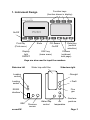
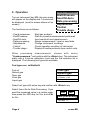
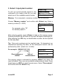
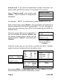
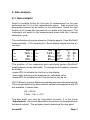
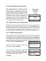
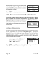
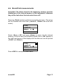
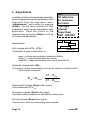
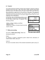
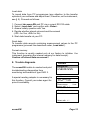
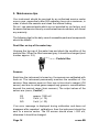
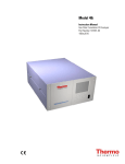
Creative technology made by rbr
Operating Instructions
rbr-Computertechnik GmbH, Am Großen Teich 2, 58640 Iserlohn
INDEX
Page
1. Instrument Design
2. Operation
3. Select / Input plant number
4. Gas measurement
4.1. Combustion analysis
4.2. CO measurement (Flue gas canal check)
4.3. O2 multi-hole measurement
4.4. Draft / Pressure measurement
4.4.1. Draft measurement
4.4.2. Pressure measurement
4.5. Soot / Oil derivative
4.6. Store / Print measurement
5. Adjustments
6. Control
7. Data Processing
8. Trouble Diagnostic
9. Maintenance Tips
10. Technical Data
Page 2
3
4
5
7
8
9
9
10
10
11
12
14
14
15
16
18
ecom-EN
Function keys
(function shown in display)
1. Instrument Design
PUSH
On/Off
Store
Print key
(Print menu)
Display
light
ON/OFF
Enter key
(confirm
selection)
CO sensor
On/Off
ESC key
(leave menu)
Cursors
(up/down/
next page)
Keys are also used to input the numbers
Sideview left
Water trap with filter
Sideview right
Loading
control
- Draught
Loading
socket
+ Draft
RS232
interface
Flue
gas
GSK
ecom-EN
Pressure
sensor
Water trap
control
Air
temperature
Gas temperature
Page 3
2. Operation
Turn on instrument (key I/O), the main menu
will appear on the display and 7 choices will
be displayed (scroll to access others not on
screen).
The functions are as follows:
- Comb.measurem.:
- Draft/Pressure:
- Soot/Oil deriv:
- Data processing:
- Adjustments:
- Control:
- Trouble diagn.:
Comb.measurem.
Draft/Pressure
Soot/Oil deriv.
Data processing
Adjustments
Control
Trouble diagn.
Start gas analysis
Draft or pressure measurement performed
Input results of soot measurement
Assign measurement / Load or send data
Change instrument´s settings
Check operation condition of instrument
Display of trouble protocols from control units.
When processing measurements, choose with cursor
”Comb.measurem.” and confirm with the <Enter> key. The instrument
starts with a 3-minute calibration cycle and the fuel selection list is
displayed. The following fuel types are available:
Fuel types acc. to BImSchV
Fuel oil
Natural gas
Town gas
Coke gas
Liquid gas
Fuel type
Natural gas
CO2max : 11.7
A1-Factor : 0.35
Select with ↑↓!
Select fuel type with arrow key and confirm with <Enter> key.
Select Yes or No for Data Processing. If you
want the measured value in a certain order,
then press the <F1> key for Yes, and <F4>
for No.
Page 4
Yes
No
Data processing
Quit with ↵
ecom-EN
3. Select / Input plant number
To call up a plant already stored in the
instrument or to create a new file, you may
select one of the available search modes.
Select by:
Search word
Memory number
Select with
↑↓!
Memory: For a new plant, a memory number can be allocated.
Choose ”Memory number” and confirm with <Enter> key. Enter a
memory number (0 - 4000).
Memory number
Input:
For example, enter ”0”
for memory space 0.
0
After entering number, press <Enter> to take up this memory space.
Pressing the <F3> key will seek out the next free space (starting by 0).
After pressing the <F4> key, an identification number can be inputted
for the new plant.
Tip: Since only numbers can be inputted (max. 16 characters), we
recommend inputting the date, so the subsequent search can be
performed by date (search acc. to date).
For example: 0000001.25.11.99
Number:
Input:
Plant number or
similar
Date of
measurement
0000001.25.11.99
The memory space is activated by pressing <Enter> key when the
input is finished. Then one can access the measurement mode. Press
hereto twice on <ESC> to reach the main menu. Select ”Gas analysis”
and confirm with the <Enter> key.
ecom-EN
Page 5
Search word: If you know the identification number of the plant, the
search mode will find the number if it is already in the memory.
Select ”Search word” and confirm with
<Enter>. Input 4 numbers to recognize the
equipment.
Search word
Input:
25.11
For example: ”25.11” for identification number 0000001.25.11.99
After number input, press <Enter>. The programme will propose all
stored numbers with this figures configuration. You can view each of
them using the arrow key (use <F1> for the beginning and <F2> for
selection end).
Once the correct data record is identified, it
can be activated by pressing <Enter> and
the stored measurement values can be
viewed (choose “ Look at” and confirm with
<Enter>).
F1:Begin
F2: End
F3:Empty
0000001.25.11.99
Memory number
8 M
Measured values
available
Using the cursor key, you can call up -one after the other- 4 display
pages covering all measured and calculated values.
Date
25.11.99
Time
10:35:56
0000001.25.11.99
Memory number
O2
CO2
CO
NO
T.Gas
T.Air
Losses
Eff.
3.2
13.1
12
52
184
20
7.5
92.5
%
%
ppm
ppm
°C
°C
%
%
CO-measure.
8
O2
17.5 %
CO
0.0% 738 ppm
CO
123 ppm
Excess air
7.00
BImSchV : keys ↑↓!
Soot/Oil trace
Draught
-0.08 hPa
T.Boiler
65 °C
1.Soot-meas.
0.5
2.Soot-meas.
0.3
3.Soot-meas.
0.7
Oil trace
No
O2 multi-hole meas.
O2
19.5 %
BImSchV : keys
↑↓
!
Press twice <ESC>, ”Comb.measurem.” and then <Enter> to enable
the recording of the current measurement values.
Page 6
ecom-EN
4. Gas analysis
4.1. Gas analysis
Select a suitable probe for the type of measurement to be now
performed and fix it at the measurement place. Also connect the
temperature sensor for air suction to the instrument. Check the right
fixation of all hoses and connections on probe and instrument. The
instrument will switch to the measurement mode after the 3-minute
calibration cycle.
The combustion values are shown on 4 display pages. (3 are BImSchV
measurements, 1 CO mesurement. Scroll display pages with the arrow key).
O2
CO2
T.Air
T.Gas
4.0 %
12.5 %
20 °C
212 °C
O2
CO2
CO
NO
4.0 %
12.5 %
30 ppm
45 ppm
O2
CO2
CO
NO
T.Gas
T.Air
Losses
Eff
4.0
12.5
30
45
166
20
7.0
93.0
%
%
ppm
ppm
°C
°C
%
%
The position of the measured and calculated values (BImSchV
measurement) is free selectable. To change the succession, process
as follows:
-press <F1> to activate the first line on the display,
-select with arrow keys the measured or calculated value,
-press <F1> to activate the next line and so on and so on...
CO2, Efficiency, Losses, Excess air and dew point are calculated values.
They are calculated only when realistic values for temperature and O2
are available. It means that:
O2 < 20.5%
T.Gas – T.Air > +5°C
The dew point can only be calculated correctly, if in the menu
“Adjustments” the current barometric air pressure under adjustments
has been entered. The analyser cannot determine the dew point.
ecom-EN
Page 7
Correct values are displayed after a short time, necessitated by the
gas transport to the sensors and once a stable electrochemical reaction
is given at the sensors. This time lies between 1 and 1 ½ minute. Wait
for the values to get stable before storing, printing and evaluating them.
If the gas values still fluctuate more than 2 ppm, there may unstable
draught conditions in the gas channel.
Measurement
is stored in
Once the measured values are stable and
temporary
the results can be printed, press <Store> to
memory
transfer the values in a temporary memory
(note: store separately BImSchV and CO
measurements). The data is stored in this
temporary memory for a later printout or for
a final data storage (you can view the values
in the intermediate memory by pressing
<F4>).
O2
CO2
CO
NO
T.Gas
T.Air
Losses
Eta
4.0
12.5
30
45
166
20
7.0
93.0
% m
%
ppm
ppm
°C
°C
%
%
4.2. CO measurement (Flue gas channel check)
The flue gas channel check, also called CO measurement, is the specific
control of said channel by gas-fired plants, performed under safety
aspects.
The CO content is measured in the flue gas channel after the gas has
been enriched with surrounding air and is converted in an undiluted
value (residual oxygen content in combustion gas = 0%). As the gas
behaviour after air addition is no longer homogenous due to secondary
air, and the main stream core determination can be erratic, this gas
analysis is performed across the whole diameter of the exhaust pipe.
A multi-hole probe (optional accessory) is the
Measurement
ideal sampling tool hereto. The calculated CO
is stored in
value shown by “CO 0.0%” corresponds to
temporary
the measured CO content, supposing that
storage
in the same gas volume the 02 content is
0%. This is consequently the undiluted CO CO-measur.
m
content in the flue gas. Once the measured
O2
17.5 %
value is stable, press <Store> in order to CO
0.0% 738 ppm
CO
123 ppm
transfer the value in temporary storage.
Excess air
7.00
BImSchV: keys
Page 8
↑↓
!
ecom-EN
4.3. O2 multi-hole measurement
This measurement is used at roomindependant plant e.g. useful heat firing
plants. It will be investigated if flue gas enter
in the combustion air (O2 content is then
reduced) and influence herewith on the
combustion quality. For this measurement a
multi-hole probe (optional accessory) is
necessary. Once the value displayed is
stable, press the key <Store> and the value
is stored in the intermediate memory.
Measurement
is stored in
temporary
storage
m
O2 multi-hole meas.
O2
19.5 %
BImSchV : keys
↑↓
!
4.4. Draft / Pressure measurement
Besides the draught respectively differential pressure measurement
performed by the internal draught sensor, the ecom-EN offers a
connection possibility for an external pressure sensor ( 0 - 100 mbar or
0 -500 mbar) for the determination of pressure conditions in the
surrounding field of combustion places (e.g. gas nozzle pressure).
4.4.1. Draft measurement
The gas measurement mode already provide with a trend indication of
the draught value. As the differential pressure sensor is very sensitive
and tends to drift, the value will not be recorded by pressing <Store>.
It is consequently advisable to recalibrate this sensor prior to the
practical measurement and results printing. Enter the measurement
mode by selecting „Draft/Pressure“.
Draft/Pressure
Select the internal pressure sensor (use
arrow keys and then <Enter>).
The current value is displayed as well as the
advice to zero the sensor. Remove the draft
hose from the instrument and press <Enter>.
The sensor is then reset to zero.
ecom-EN
Internal 0..20.00 hPa
External 0..100.0 hPa
External 0..500.0 hPa
Set zero point
Draft
0.12 hPa
Stored value:
Draft
-.-- hPa
Page 9
Reconnect the draught hose. The exact value
is then displayed. Press <Store> to store it
together with the gas mesurement results in
the temporary memory.
Set zero point
Draft
0.12 hPa
Stored value:
Draft
0.12 hPa
Press <ESC> to escape pressure measurement.
4.4.2. Pressure measurement with external sensor
Connect the external pressure sensor to the instrument where labeled
(Aux). Initialise the pressure measurement by selecting „Draft/
Pressure“. Select external sensor (Cursor to; <Enter>) and re-zero
(<F1>). Place the sensor at the measurement
Draft/Pressure
point. Once the mesurement value is stable,
Internal 0..20.00 hPa
it can be stored in the temporary memory for
External 0..100.0 hPa
later printout.
External 0..500.0 hPa
4.5. Soot / Oil derivative
The measured values for boiler temperature, soot number and oil trace
can be entered in the sub-menu „Soot/Oil deriv.“. Select the
appropriate line on the display and press <Enter>. The input for boiler
temperature, soot number 1 - 3 can be keyed in respectively. After
pressing <Enter> the data is recorded. The result of the oil trace check
is to be documented as follows:
- place cursor on line „Oil deriv.“
- press <Enter> to register
(„No“; „Yes“ or „---“)
Soot/Oil deriv.
T.Boiler
1. Soot-meas.
2. Soot meas.
3. Soot-meas.
Oil trace
--- °C
---------
Press <ESC> to quit this menu when all required inputs have been
made. The measurement is now complete.
Page 10
ecom-EN
4.6. Store/Print measurements
Important: The values stored in the temporary memory must be
transferred in the internal memory of the instrument, otherwise
they will be lost when the instrument turns off !
Press key <Print> (printer symbol) to access the print menu. The values
can be checked one more time („Look at“; <Enter> and scroll with
cursor).
Print
Look at
Store -> M
Select with
↑↓
!
Select „Store -> M“ and press <Enter> to store into the internal
memory. Once the data is successfully stored, then a „M“ appears in
the right hand corner of the display and the data can now be printed
(„Print“ and <Enter>).
Print
Look at
Store -> M
Select with
↑↓
M
!
Press <ESC> to escape to main menu.
ecom-EN
Page 11
5. Adjustments
Unit
O2-reference
Air pressure
Set clock
Fuel type
Internal
Paper feed
GSK ON/OFF
In addition to the functions already described,
various adjustments can be performed in this
instrument. From the main menu, select
„Adjustments“ and confirm by pressing
<Enter>. You will find a selection of other
parameters, which can be adjusted for each
application. Place the cursor on the
requested line and press <Enter> to call up
or change the adjustment.
ppm
Explanations:
mg/m3
mg/kwh
undiluted
Unit (change with <F1> - <F3>):
-Calculation of gas concentration in:
CO
9999ppm
-ppm = volume concentration (parts per million)
-mg/m3 = mass concentration by volume
-mg/kWh = mass concentration by unit of productivity
Undiluted (change with <F4>):
-Conversion of gas concentration for a given content of reference O2
-Formula for conversion:
Eref = Emeas *
21 - O2ref
21 - O2meas
Reference-O2 (press <Enter> then input):
-Input reference-O2 (O2ref)
Air pressure (press <Enter> then input):
-Input barometric pressure for calculation of dew point
Set clock (press <Enter> then input):
-Correct inner clock by overwritting new numbers
Page 12
ecom-EN
Fuel type (press <Enter> and then select):
-Change the type of fuel (e.g. by measurements at combi plants)
Paper feed (press <Enter>):
-paper feed line by line
Internal (access menu with <Enter>):
-further instrument´s adjustments
Keyboard beep
Printer contrast
Baudrate
Handshake
Keyboard beep (press <F1> for Yes / <F4> for No):
-Acoustic signal when keyboard is pressed
Printer contrast (0..9) (press <Enter> then select):
-Set contrast of printer
Baudrate (adjustment with Cursor keys):
-Data transfer speed via RS 232 (1200 -19200 Baud)
Handshake (key <F1> for Yes / <F4> for No):
-Adjustment of data transfer option
ecom-EN
Page 13
6. Control
The electrochemical sensors used for gas analysis underlie a wearing
process along the time. They alter their output values along their
operation time, this depending on the gas concentration, the time they
are submitted to gas and on the purity of the gas. The program
(software) monitors the sensors and corrects drifts. If the drift is too
important and could lead to an incorrect measurement, then an error
message will be displayed.
O2
1034 mV
In this case, the corresponding sensor must
CO
-10 mV
be changed. The sensors´ status is indicated
NO
5 mV
Batt
6.42 Volt
in the control menu with, in addition, the
Operat. hours 7.39
following values:
Tel.No. 02371/945-5
Ser. Nr. 0047
-battery voltage (loading condition)
-operation time
-telephone number of nearest service center
-serial number
7. Data processing
Select
Look at
Load data
Transfer data
Format memory
The menu „Data processing“ offers the
following functions:
Select:
To identify or create a combustion plant´s data file for allocation of
measurement data (see § 3).
Look at:
To look at recorded values of the selected combustion plant (see § 3).
Page 14
ecom-EN
Load data:
To import data from PC programmes (pay attention to the transfer
options of your software and adjust them, if need be, on the instrument,
see § 5). Proceed as follows:
1. Connect rbr-ecom EN and PC via a current RS 232 cable.
2. Select „Load data“ and confirm with <Enter>.
3. Answer safety question with Yes.
4. Decide whether stored values should be erased
(<F1> for Yes, <F4> for No).
5. Start data transfer at your PC.
Send data:
To transfer data records containing measurement values to the PC
programme (proceed like described under „Load data“).
Format memory:
This function is usually needed only at our factory to initialise the
instrument (preparing the internal memory for data receipt).
Caution: all stored data are erased !
8. Trouble diagnosis
The ecom-EN is able to readout and print
troubleshooting diagnostics from
monitoring instruments of type LMG 2.
A special reading adapter is necessary for
this function. Consult your sales agent for
price & availability.
Trouble
diagnosis
LMG2X.XXX
LMG2
Vent. /Safety time
30 sec
3 sec
Oper. counter
1522
Flame recogn.
2 sec
Select with ↑↓ !
Trouble cause
Old software stand !
Select with
ecom-EN
↑↓
!
Page 15
9. Maintenance tips
Your instrument should be serviced by an authorised service center
once a year, respectively after 500 operating hours at a maximum, in
order to check the sensors and clean the internal tubing.
Do not use sensors/parts which are not provided by our factory, and
be aware that service done by unauthorised service centers, will cancel
any warranty.
The following tips for the daily care of accessible parts and components
should be helpful:
Dust filter on top of the water trap
Unscrew the top cap of the water trap and check the condition of the
particle filter. When the filter becomes grey, it should be changed (soot
number approx. 2-3).
Particle filter
Sensors
Each time the instrument is turned on, the sensors are calibrated with
fresh air. The instrument permanently monitors the condition of the
sensors. New sensors wear out from use in time due to reagent (O2
sensor) and due to soiled gases respectively gases in concentrations
beyond the nominal range (toxic sensors). The output values of the
sensor are (menu „Control“) :
O2
CO
NO
approx. 1000 mV
0 mV (+/- 70)
0 mV (+/- 30)
If an error message is displayed during calibration and does not
disappear after repeated calibrations, then the instrument should be
sent to a service center. The O2 sensor should show > 200 mV,
otherwise it should be changed.
Page 16
ecom-EN
The internal program applies an upper limit value for each sensor. By
exceeding, a magnetic switch flows fresh air to the sensor (respectively
to all sensors).
The CO sensor limit is set at 4.000 ppm and corresponds for other
toxic sensors (if available in the instrument) to their respective
measurement range end value.
Mains Power
The battery makes mains power independent operation possible. The
battery is automatically loaded when the instrument is plugged in. It
should be expressly re-loaded when the voltage displayed (menu
„Control“) is lower than 5.8 V. The instrument will indeed stop working
by 5.5 V.
Sampling probe and hose
Probe and hose must be cleaned regularly, correspondingly to the
frequency of use, thus in order to prevent particles from lodging and
early ware due to corrosion.
The hose can be released from the probe and instrument and cleaned
(use warm water and then blow out to dry).
Replace paper roll
Press slightly on the paper roll drawer to release the lock. Pull out the
paper drawer and eject -if need be- residual paper from the printer
(„Adjustments“, „Paper feed“ and then <Enter>).
Extract the paper shaft and put a new printer roll on the shaft. Reposition the printer shaft in the fixation. Insert the paper roll end through
the slot. Press „Adjustments“, „Paper feed“ and then <Enter> to pull
out approx. 10 cm paper. Push the drawer back in the compartment.
Push carefully the paper drawer until it locks.
ecom-EN
Page 17
10. Technical data
Parameter
Range
O2
0 ... 21 % vol
CO
0 ... 4.000 ppm
NO (option)
0 ... 2.000 ppm
CO2
0 ... CO2max
T-G
0 ... 500 °C
T-A
0 ... 99 °C
Pressure
0 ... +/- 20 hPa
Efficiency
0 ... 99,9 %
Losses
0 ... 99,9 %
Lambda
1 ... ∞
CO-undiluted
(ref. 02 adjustable)
Dew point of combustion gas
Power supply
Printer
Display
Size
Weight
Measurement
principle
electrochemical
electrochemical
electrochemical
calculated
NiCr/Ni
semiconductor
DMS-bridge
calculated
calculated
calculated
calculated
calculated
230 V / 50~; battery 6 V / 1,2 Ah
Integrated; 58mm paper width
Graphic display; backlight
190 mm x 160 mm x 75 mm
approx. 3500g complete with sampling system
Subject to technical changes
12.2004
rbr Computertechnik GmbH
Am Großen Teich 2
D-58640 Iserlohn (Sümmern)
Telefon: +49 (0) 23 71 - 9 45-5
Telefax: +49 (0) 23 71 - 4 03 05
Internet: http://www.rbr.de
eMail: [email protected]
Page 18
ecom-EN