1
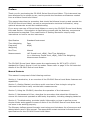
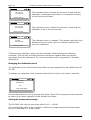
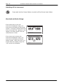
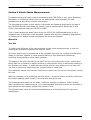
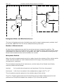
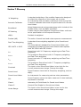
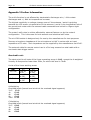
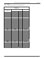
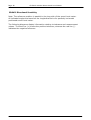
CR:261S Vehicle Noise Sound Level Meter
User Manual for the
CR:261S Vehicle Noise
Measurement Sound Level
Meter
This manual, the software to which it relates, the
program code and drawings are all:
© Copyright Cirrus Research plc 1989-2007
Page 1
Page 2
CR:261S Vehicle Noise Sound Level Meter
The content of this manual, any illustrations, technical information and descriptions within this document
were correct at the time of going to print. Cirrus Research plc reserves the right to make any changes
necessary, without notice, in line with the policy of continuing product development and improvement.
No part of this publication may be duplicated, reprinted, stored in a data processing system or transmitted
by electronic, mechanical, photographic or other means, or recorded, translated, edited, abridged or
expanded without the prior written consent of Cirrus Research plc.
No liability is accepted for any inaccuracies or omissions in this manual, although due care has been taken
to ensure that is it complete and accurate as possible.
Accessories supplied by Cirrus Research plc have been designed for use with the instrumentation
manufactured by Cirrus Research plc. No responsibility is accepted for damage caused by the use of any
other parts or accessories.
In order to take account of a policy of continual development, Cirrus Research plc reserves the right to
change any of the information contained in this publication without prior notice.
Produced by Cirrus Research plc, Acoustic House, Bridlington Road, Hunmanby, North Yorkshire, YO14
0PH, United Kingdom.
© Copyright Cirrus Research plc 2007
Reference Number 07/01/CR:261S/01
Document Printing Date Friday, 02 February 2007
CR:261S Vehicle Noise Sound Level Meter
Page 3
Preface ......................................................................................................................... 5
Manual Contents ......................................................................................................... 5
Messages and Symbols ................................................................................................ 6
Section 1 Introduction.................................................................................................. 7
Main Features............................................................................................................. 7
Measurement Functions ............................................................................................... 7
Single Measurement Mode............................................................................................ 7
Multiple Measurement Mode .................................................................................................... 7
Options & Accessories .................................................................................................. 7
Section 2 Getting Started ............................................................................................. 8
How to... ................................................................................................................... 8
Make a Single Mode Measurement............................................................................................ 8
Make Multiple Measurements ................................................................................................... 8
Quick Start................................................................................................................. 8
Section 3 Using the CR:261S Sound Level Meter......................................................... 11
Unpacking and checking the Sound Level Meter ............................................................. 11
Batteries .............................................................................................................................11
Windshield ...........................................................................................................................12
Keypad Functions ...................................................................................................... 13
Calibrating the Sound Level Meter ...........................................................................................13
Changing the Calibration Level................................................................................................14
Setting the measurement range .................................................................................. 14
Setting the measurement modes ................................................................................. 15
Single Measurement Mode.......................................................................................... 15
Multiple Measurement Mode with the Remote Control Cable ........................................................15
Switching off the instrument ....................................................................................... 16
Overload and Under-Range......................................................................................... 16
Section 4 Vehicle Noise Measurements....................................................................... 17
Overview ................................................................................................................. 17
Test Site..............................................................................................................................17
Background Noise and Wind Interference .................................................................................18
Number of Measurements ......................................................................................................18
Microphone Position................................................................................................... 18
Section 5 Maintenance & Care .................................................................................... 24
Section 6 Troubleshooting .......................................................................................... 25
Basics ..................................................................................................................... 25
Calibration ............................................................................................................... 25
Measurements & Settings ........................................................................................... 26
Section 7 Glossary ...................................................................................................... 27
Appendix 1 Rating Plate Information ......................................................................... 28
Appendix 2 Specifications........................................................................................... 31
Instrument Versions .................................................................................................. 31
Applicable Standards ................................................................................................. 31
Sound Level Meter ................................................................................................................31
Microphone ..............................................................................................................
Microphone Preamplifier .............................................................................................
Extension cables .......................................................................................................
Time Weightings .......................................................................................................
Frequency Weightings................................................................................................
Amplitude Weighting .................................................................................................
Measurement Range ..................................................................................................
Noise Floor (Typical)..................................................................................................
Available Measurements.............................................................................................
31
31
31
31
31
31
31
31
31
Page 4
CR:261S Vehicle Noise Sound Level Meter
Single Measurement Mode: ....................................................................................................31
Multiple Measurement Mode: ..................................................................................................32
Measurement Storage................................................................................................
Display ....................................................................................................................
Weight ....................................................................................................................
Dimensions ..............................................................................................................
Batteries..................................................................................................................
Battery Life ..............................................................................................................
Environmental ..........................................................................................................
32
32
32
32
32
32
32
Temperature ........................................................................................................................32
Humidity .............................................................................................................................32
Influence of Mechanical Vibration ................................................................................
External Connections .................................................................................................
Output Cables...........................................................................................................
Electromagnetic Performance......................................................................................
33
33
33
33
Appendix 3 Further Information ................................................................................. 34
Overload Levels ........................................................................................................ 34
CR:261S Directional Sensitivity...............................................................................................36
Horizontal............................................................................................................................37
Vertical ...............................................................................................................................39
Directional Sensitivity with UA:237 Windshield .............................................................. 42
Influence of the UA:237 Windshield ............................................................................. 46
Data Table ............................................................................................................... 48
Appendix 4 CE Certificate of Comformance................................................................. 50
Equipment Description ............................................................................................... 50
Guarantee................................................................................................................... 51
Cirrus Research Offices .............................................................................................. 51
CR:261S Vehicle Noise Sound Level Meter
Page 5
Preface
Thank you for purchasing the CR:261S Series Sound Level Meter. This instrument has
been designed to be simple to use, and to provide the functions and features needed
from a modern Sound Level Meter.
This manual describes the procedure that should be followed to set up and operate the
CR:261S Sound Level Meter, as well as comprehensive technical information, using
optional accessories as well as troubleshooting.
If you are a new user of Sound Level Meters or new to the CR:261S Sound Level Meter,
first read Section 1 Introduction to familiarise yourself with the features, components
and accessories supplied. Then read Section 2 Getting Started for step-by-step
instructions on how to use the instrument.
Specification
Standard Instrument
Time Weighting
Fast
Frequency
Weighting
dB(A)
Run Time
Manual
Measurements
LAF Sound Level, dB(A), Fast Time Weighting
LAFmax Maximum Sound Level, dB(A), Fast Time Weighting
Measurement Duration
The CR:261S Sound Level Meter meets the requirements for IEC 61672-1:2003
standard for Class 1 Group X in all its modes. Please refer to page 31 for full technical
details of the CR:261S Sound Level Meter.
Manual Contents
This manual is composed of the following sections.
Section 1, Introduction, is an overview of the CR:261S Sound Level Meter features and
capabilities.
Section 2, Getting Started, provides a quick overview of how to begin using the
instrument and how to carry out the basic measurements.
Section 3, Using the CR:261S, describes the operation of the instrument.
Section 5, Maintenance & Care, describes the procedure that should be followed to
ensure the instrument operates as efficiently as possible, including changing batteries.
Section 6, Troubleshooting, provides helpful information on how to perform some
simple checks and suggests courses of action if the CR:261S Sound Level Meter does
not seem to be working properly.
The Glossary defines general Acoustic terminology and includes a list of acronyms and
abbreviations used in this manual. The appendices contain technical information and
specifications for the CR:261S Sound Level Meter.
Page 6
CR:261S Vehicle Noise Sound Level Meter
Messages and Symbols
Messages are used in this manual to bring important information to your attention. The
different message types are indicated as shown below.
Pay attention! A caution informs you that improper use of the equipment or
failure to follow instructions may cause data loss or may damage the
equipment.
i
Please read. A note is a hint or advice that helps you make best use of the
equipment and accessories.
CR:261S Vehicle Noise Sound Level Meter
Page 7
Section 1 Introduction
Main Features
Measurement Functions
The Instrument has two main modes, the first being single measurement mode, the
second being multiple measurement mode.
Single Measurement Mode
In Single Measurement Mode, the instrument displays LAF and LAFmax. In this mode the
instrument is controlled by the keypad.
Multiple Measurement Mode
In Multiple Measurement Mode, the instrument displays the currnet LAFmax and the last
two LAFmax’s. In this mode the instrument is controlled through a push button on a lead
that connects to the bottom of the instrument
Options & Accessories
The CR:261S also available with a range of options and accessories that can enhance
the performance and applications of the instrument. For full details, please contact
Cirrus Research plc or your local representative.
The most commonly used accessories are listed below.
CR:511F
CR:590
UA:237
CK:250
CP:65
CT:1
ZL:261S
Acoustic Calibrator with PTB Type Approval
Barometer for use with CR:511F Acoustic Calibrator
Windshield
Carrying Case
Carrying Pouch for Sound Level Meter
Tripod
External Remote Control Cable (5m)
Page 8
CR:261S Vehicle Noise Sound Level Meter
Section 2 Getting Started
How to...
These example settings are designed to demonstrate the different configurations that
are available from the CR:261S Sound Level Meter.
Make a Single Mode Measurement
Switch on
Calibrate
Press the Reset Key
Make Multiple Measurements
Switch on
Calibrate
Insert external switch cable
Hold down the button to start measurement
Release the button to end measurement
Repeat
Quick Start
The information in this section is the same as that given in the CR:261 Quick Setup
Guide. For more detailed information, please see section 3.
1. Switch On
Cirrus
Press the Power button to switch
on the Sound Level Meter
Re s e a r c h p l c
CR:261S 1.00
The instrument will display the
start up screen, and then will
display the Single Mode screen
60
130
LAF dB
t = 00:01:23
LAFMax dB
CR:261S Vehicle Noise Sound Level Meter
Page 9
2. Calibration
Attach the Acoustic Calibrator to
the Sound Level Meter and switch
to the 94dB level setting.
Press the Cal key to start the
calibration procedure.
Cal
Attaching the Calibrator
Gently push and twist the
calibrator clockwise.
When the calibration is complete,
the display will change to show
the calibration level.
Remove the Acoustic Calibrator,
switch off the calibrator and store.
Calibrating
Please wait
3. Mode Select
With the cable not plugged in the
instrument runs in single
measurement mode
With the cable plugged in the
instrument goes into multiple
measurement mode
de dic
60
at ed
130
LAF d B
Cir
ru
Re
to
s ea
no is
e
rc h
me
as ur
s
pl c
em
en
t
60
LAFm ax d B
130
LAFmax
LAFm ax
LAFm ax
___._
___._
___._
dB
t
=
00:01:23
t
de dic
at ed
Cir
Re
to
s ea
no ise
ru s
rc h
me
as ure
me
pl c
n
t
=
00:01:23
dB
dB
Page 10
CR:261S Vehicle Noise Sound Level Meter
4. Start Measurement
60
Single Measurement Mode
Pressing the Reset key on the
keypad clears the LAFmax hold
functions and starts a new
measurement.
Multiple Measurement Mode
When the cable is inserted and
the button is held in it displays
the LAFmax value, when the
button is released and the
depressed again, it moves the
last LAFmax value to the next
slot along and then starts a new
measurement.
5. Switch off
Press and hold the Power button
to switch off the instrument.
130
LAF dB
LAFMax dB
t = 00:01:23
60
130
LAFMax
___._
dB
t = 00:01:23
LAFMax
85.8
dB
LAFMax
85.2
dB
CR:261S Vehicle Noise Sound Level Meter
Page 11
Section 3 Using the CR:261S Sound Level Meter
Unpacking and checking the Sound Level Meter
Carefully remove the instrument from its shipping container and inspect it for possible
damage or missing items. If the meter appears to be damaged or something is missing,
contact Cirrus Research plc or your local representative immediately.
The CR:261S instrument is supplied with the following standard accessories:
CR:261S User Manual
Batteries 2 x AA
If you have ordered the instrument as a complete measurement kit, you will have also
received some further items such as an Acoustic Calibrator, Carrying Case and
Windshield.
Please refer to the manual supplied with the Acoustic Calibrator (where supplied) for
details of fitting the battery and operation of this unit.
Batteries
The batteries of the CR:261S are located behind the cover on the bottom of the
instrument. Slide the cover to the right hand side to remove and to access the battery
holder.
BATTERY COVER
Ensure the instrument is switched off. Remove the battery holder from the instrument
and insert the batteries. The CR:260 instruments uses two AA type batteries, also
known as LR6.
(1) Batteries
(2) External Interface Socket (Not Used)
(3) Remote Control Socket
3
Ensure that the batteries are inserted correctly. DO NOT reverse the polarity
of the batteries as this may cause damage to the instrument.
Page 12
CR:261S Vehicle Noise Sound Level Meter
Windshield
The CR:261S can be used with a UA:237 Foam Windshield which will reduce the noise
levels generated by air turbulence over the microphone capsule.
The windshield can also be used to protect the microphone capsule of the Sound Level
Meter from dust and fluids which may affect the performance of the instrument.
To use the UA:237 Windshield, push the hole in the windshield over the microphone of
the Sound Level Meter.
The UA:237 Windshield must be removed before the Sound Level Meter can be
calibrated.
CR:261S Vehicle Noise Sound Level Meter
Page 13
Keypad Functions
Measurement Mode
Reset
Select the measurement mode & view the current
measurement mode settings
Cal
Press the CAL button to start the calibration procedure
Press the Power Button to switch on the Sound Level Meter
Cirrus
Re s e a r c h p l c
CR:261S 1.00
When the instrument is switched on, the Start-up screen
will be displayed, and after a short time, the display will
change to show the last measurement that was made.
If there are no measurements in memory, the instrument
will indicate that there are no measurements in the
memory.
Calibrating the Sound Level Meter
Turn the acoustic calibrator level on the Acoustic Calibrator
Gently push the calibrator onto the microphone capsule, slowly twisting clockwise.
Cal
Press the CAL button to start the calibration procedure
During the calibration, the instrument will display the
calibration status.
Calibrating
Please wait
60
130
Calibrated
to 93.7 dBA
If the calibration is successful, the instrument will display
the calibration level. Press the Start button to begin a new
measurement or to return to the main screen.
Reset to measure
If the calibration is not successful, the instrument will display an error message. These
are shown below.
CR:261S Vehicle Noise Sound Level Meter
Page 14
60
130
The calibration level is below the set level. Check that the
Calibrator is switched on and that it is connected correctly
to the Sound Level Meter.
SPL Too Low
Not Calibrated
Reset to measure
60
130
SPL Too high
Not Calibrated
The calibration level is above the set level. Check that the
Calibrator is set to the correct level.
Reset to measure
60
130
The calibration level is unstable. This maybe caused by high
background noise levels. Move to a quieter location and
retry the calibration.
Unstable
Not Calibrated
Reset to measure
To Remove the calibrator, gently pull the calibrator whilst twisting the calibrator
clockwise. This will help to ensure that the microphone capsule does not become
unscrewed from the instrument. For more information refer to Appendix 4 “Acoustic
Calibrators”.
Changing the Calibration Level
The calibration level of the Sound Level Meter can be adjusted from the default level of
93.7dB.
To change the calibration level, press and hold the Cal key for more than 2 seconds.
60
130
Press Cal to
change level
93.7
Then Press Reset
Use the Reset Key to cycle up through the levels. Press CAL to accept the new level and
to return to the main operation of the Sound Level Meter.
Setting the measurement range
The CR:261S only has the one range which is 60 – 130 dB
It is vital that the noise to be recorded, is within this range otherwise the instrument
will be in Overload or in Under-range.
CR:261S Vehicle Noise Sound Level Meter
Page 15
Setting the measurement modes
Single Measurement Mode
In Single Measurement Mode, the instrument displays LAF and LAFmax. In this mode the
instrument is controlled by the keypad.
Pressing the Reset key will reset the run duration and the LAFmax hold value
Multiple Measurement Mode with the Remote Control Cable
In Multiple Measurement Mode, the instrument displays the currnet LAFmax and the last
two LAFmax’s. In this mode the instrument is controlled through a push button on a lead
that connects to the bottom of the instrument.
When the ZL:261S Remote Control cable is plugged into the CR:261S Sound Level
Meter, the instrument will automatically switch to the Multiple Measurement Mode.
When first entering this mode there are no levels displayed untill the first measurement
is taken.
When a fourth measurement is taken the very first measurement is removed and so
forth.
When in this mode the cable does not effect any measurement perameters.
de di
60
c at
ed
130
LAF d B
C ir
rus
Re
to
no
sea
is e
r ch
mea
s ur
em
pl c
en
t
60
LAFm ax d B
130
LAFm ax
LAFm ax
LAFm ax
___._
___._
___._
dB
t
=
00:01:23
t
de di
c at
ed
C ir
rus
Re
to
sea
noi
se
r ch
mea
s ur
em
pl c
en
t
=
00:01:23
dB
dB
Page 16
CR:261S Vehicle Noise Sound Level Meter
Switching off the instrument
Press and hold the Power Button to switch off the Sound Level Meter.
Overload and Under-Range
If the noise level is over the
instruments displayed range, the
instrument will display the Overload
symbol. If during a measurement the
level is exceeded “OL” appears on the
display, this stays present until the
measurement is reset.
If the noise level is below the
instruments displayed range, the
instrument will display the UnderRange symbol. When the level is no
longer below the display range the
“UR” symbol will disappear.
60
130
LAF d B
t
OL
LA Fmax d B
= 00:01:23
60
1 30
LAF dB
LA Fmax dB
UR
t = 00:01:23
CR:261S Vehicle Noise Sound Level Meter
Page 17
Section 4 Vehicle Noise Measurements
If measurements are being made in accordance with ISO 5130 or any other Standard,
Regulation or Guideline always refer to the appropriate documentation for test
procedures and any other relevant information.
The information contain in this section is provided as a general guide as to the use of
the CR:261S Sound Level Meter for vehicle noise measurements. Reference to ISO
5130 in this manual refers to ISO 5130-1982.
Text in italics below has been taken from the ISO 5130-1982 standard but is not a
verbatim copy of the text in the standard. Always refer the any Standard, Regulations
or Guidelines for details of test procedures the must be followed.
Overview
Test Site
To reduce the influence of the surroundings on the noise measurements, a test site
meeting the following requirements shall be used:
Any open space may be considered to be a suitable test site if it consists of a flat area
made of concrete, asphalt or hard material having a high acoustical reflectivity,
excluding compressed or other earth surfaces.
The edges of the test site shall be at least 3m from the extremities of the vehicle and
there shall be no feature or object present on the test site likely to affect the reading of
the Sound Level Meter; in particular the vehicle shall be at a distance of not less than
1m from a pavement edge when the exhaust noise is measured.
Any obstacles outside the test site shall not be closer than 3m to the microphone during
the test.
With the exception of the observer and the driver, no person whose presence influences
the meter readings shall remain in the test site during the test.
The measurements shall not be made in adverse weather conditions. Gusts of wind
shall not affect the measurements. It is recommended that tests should not be made in
wind speeds at microphone height that exceed 5 m/s.
The figures below show the recommended distances of the test areas for cars and
motorcycles.
CR:261S Vehicle Noise Sound Level Meter
Page 18
Background Noise and Wind Interference
The level of background noise (including any wind) at each measurement position shall
be at least 10dB less than the levels measured during the tests.
Number of Measurements
At least three measurements shall be carried out at each measuring position. The
measurements shall be considered to be valid if the range of three measurements made
immediately one after the other is not greater than 2dB. The arithmetic mean given by
these three measurements shall constitute the results.
Microphone Position
When the noise measurements are to be made close to the exhaust of the vehicle which
is the common location of most measurements of this type, the positioning of the
microphone is important.
The microphone capsule of the instrument, not the body of the Sound Level Meter,
must be positioned as follows:
Vertical:
In line with the exhaust but not less than 0,2m from the ground
Horizontal: 0,5m from the outlet of the exhaust at an angle of 45o ± 10o
The microphone must be placed on the outside edge of the vehicle.
The CT:4 Tripod supplied with the CK:261S Sound Level Meter Measurement kit will
position the microphone capsule at a height of 0,2m from the ground.
CR:261S Vehicle Noise Sound Level Meter
Page 19
The Positioning Template supplied with the CK:261S Vehicle Noise Measurement Kit will
put the microphone at 0,5m and 45 o from the exhaust. The figures below show the
positioning of the microphone in relation to the vehicle.
Page 20
CR:261S Vehicle Noise Sound Level Meter
CR:261S Vehicle Noise Sound Level Meter
Page 21
Page 22
CR:261S Vehicle Noise Sound Level Meter
For vehicles with two or more exhausts spaced not more than 0,3m apart and
connected to a single silencer, only one measurement position shall be used. The
microphone position shall be related to the exhaust outlet nearest to the outside edge
of the vehicle.
For vehicles with a vertical exhaust (for example commercial vehicles) the microphone
shall be placed at a height of the exhaust outlet, orientated upwards and with the
vertical axis of the exhaust. It shall be placed 0,5m from the side of the vehicle nearest
to the outlet orifice.
CR:261S Vehicle Noise Sound Level Meter
Page 23
For vehicles provided with exhaust outlets spaced more than 0,3m apart, one
measurement shall be made for each outlet as if it were the only one and the highest
level noted.
Page 24
CR:261S Vehicle Noise Sound Level Meter
Section 5 Maintenance & Care
The CR:261S is a precision measurement instrument and should be treated with care.
Do not allow the instrument to be exposed to substances which may cause damage to
the components of the unit. If the instrument is to be used in an environment where
particles such as dust may come into contact with the instrument, always use a
Windshield (UA:237) to protect the microphone capsule.
The instrument is not waterproof and should not be used in situations where moisture
will form or condense on the microphone capsule or the instrument body.
If the instrument becomes dusty, wipe it down with a cloth that is lightly dampened
with water or a mild detergent. Do not use aromatic hydrocarbons, chlorinated
solvents, or methanol-based fluids when wiping down the meter.
Do not clean the microphone capsule. Do not remove the microphone grill as
this can cause severe damage to the membrane. Physical damage to the
microphone capsule is not covered by the instrument warranty.
To remove the microphone from the pre-amp make sure you grasp it by the bottom
section of the microphone not by the microphone grill. To unscrew the microphone turn
it anti-clockwise.
If you experience any problems with the operation of the instrument, refer to page 25
for basic troubleshooting. If this does not solve the problem, contact Cirrus Research
plc or your local representative for further assistance.
CR:261S Vehicle Noise Sound Level Meter
Page 25
Section 6 Troubleshooting
This section contains information which may solve simple operational problems you
may encounter. If you are unable to solve the problem or experience any problems with
the assembly or operation of the instrument contact Cirrus Research plc or your local
representative for further assistance
Basics
Symptom
The instrument does not
switch on
Possible Cause
The batteries are not fitted
The batteries are flat or
very low
The batteries are not
correctly fitted
The instrument has become
corrupted
Possible Remedy
Fit new batteries and switch
on
Fit new batteries and switch
on
Remove the batteries and
check the polarity of the
batteries
Contact your local
distributor or Cirrus
Research plc
Calibration
Symptom
The calibration fails: Too
Low
Possible Cause
The Acoustic Calibrator is
not switched on
The Acoustic Calibrator is
not fitted correctly
The microphone capsule is
loose or not fitted
Calibration level set to a
different level
The Microphone may be
damaged
The calibration fails: Too
High
The calibration fails:
Unstable
The Acoustic Calibrator is
set to a higher level than
the expected level
The background noise level
is within 15dB of the
calibration level
The Microphone may be
damaged
Possible Remedy
Switch on the Acoustic
Calibrator and retry
Check that the Acoustic
Calibrator is fitted
according to the
instructions supplied.
Check that the microphone
capsule is tight and fitted
correctly
Set the calibration level to
the value provided by the
Acoustic Calibrator.
Contact Cirrus Research plc
or your local representative
for assistance
Set the Acoustic Calibrator
to the correct level
Move to a location where
the background noise level
is more than 15dB below
the calibration level
Contact Cirrus Research plc
or your local representative
for assistance
Page 26
CR:261S Vehicle Noise Sound Level Meter
Measurements & Settings
Symptom
Overload symbol is shown
Under Range symbol is
shown
Possible Cause
The noise level is too high
for the current range
The noise level is too low
for the current range
Possible Remedy
CR:261S Vehicle Noise Sound Level Meter
Page 27
Section 7 Glossary
‘A’ Weighting
A standard weighting of the audible frequencies designed
to reflect the response of the human ear to noise.
Acoustic Calibrator
An instrument that provides a reference noise source that
is used to calibrate and check the performance of a Sound
Level Meter.
Broadband
Noise Measurements using parameters which include all the
audible noise, such as dB(A) and dB(C)
CE Marking
A label used to show that the Sound Level Meter conforms
to the specification of a European Directive
dB(A)
Decibels A weighted
Decibel (dB)
The units of sound level and noise exposure measurement
Fast Time Weighting
A standard time weighting applied by the Sound Level
Meter
IEC 61672-1:2003
The International standard for Sound Level Meter and
Integrating Averaging Sound Level Meters that replaces
both IEC 60651 and IEC 60804
LAF
Sound level with ‘A’ Frequency weighting and Fast Time
weighting
LAFmax
The maximum Sound level with ‘A’ Frequency weighting
and Fast Time weighting
LCF
Sound level with ‘C’ Frequency weighting and Fast Time
weighting
LCFmax
The maximum Sound level with ‘C’ Frequency weighting
and Fast Time weighting
Overload
The input to the Sound Level Meter is too high for the
current measurement range. Change the range
Sound Level
Sound Pressure Level with a Frequency weighting, such as
dB(A)
Sound Level Meter
An instrument for measuring various noise parameters
SPL
Sound Pressure Level, the basic measure of noise loudness,
expressed in decibels
Class 1
Laboratory & Field Grade for Sound Level Meters
Classs 2
General Field Grade for Sound Level Meter
Under Range
The input to the Sound Level Meter is too low for the
current measurement range. Change the range
Page 28
CR:261S Vehicle Noise Sound Level Meter
Appendix 1 Rating Plate Information
The CR:261S meets the requirements of IEC61672-1:2002. These specifications
require that this manual provides detailed information to verify that the specifications
are met. While much of the data required is in the body of this manual, the points
required to be detailed are listed below in the order in which they occur in the IEC
specification.
The CR:261S Sound Level Meter meets the requirements for IEC 61672-1:2003
standard for Class 1 Group X in all its modes.
The MK:226 Type 1 Electret microphone is the only microphone used with the CR:261S.
The reference direction of incidence is parallel to the sides of the case towards the
microphone capsule.
The range of measurement for SPL measurement with a standard assembly is:: 60 to 130 dBA
: 60 to 130 dBC
The self-noise is both with A and when C-evaluation under 54 dB (C-Weighting is
provided for testing purposes). This applies with the ZL:261S Remote Control Cable
attached.
For signals with a crest factor of up to 10 the top span of the unit can be reduced by up
to 17dB. This means that a signal with a crest factor of ten will produce an overload at
17dB below the expected top of the range selected. The reading of this signal will be
within the tolerances of IEC60651 up to the point where the overload occurs.
With ‘A' Frequency Weighting, the linearity range exceeds 70dB.
The reference sound pressure is 1 Pa (94dB).
The frequency weighting characteristic for measurements is A weighting.
‘F’ response is fitted with a 'Maximum Hold' on the max RMS value of each. This
parameter can be read in all modes
An acceleration of 0.1g over the frequency range 63 - 4kHz results in a reading of less
than 50dB on any axis or weighting.
1 oersted produces a reading of less than 50dB on any weighting.
The units operate from - 10 degree C to + 50 degree C with a maximum reading
change of +0.5dB but is typically less than 0.3dB.
We recommend that the operator should be at least 1m from the microphone during
measurement.
The specification is met at temperatures from -10 to +50 degrees C. The maximum
deviation amounts to +0.5 dB (typical < 0.3 dB).
The unit will meet its specification at any humidity from 0 to 95 % RH.
CR:261S Vehicle Noise Sound Level Meter
Page 29
Maximum storage temperature of +60 degree (+50 degree extended period) and 50%
RH should be observed. Care should be taken when taking an instrument rapidly from
sub zero temperatures to room temperature or above as condensation can take place
inside the instrument and temporarily affect accuracy. No long-term damage should
take place however.
The UA:237 Windshield has a small effect upon the measurement. Between 1kHz and
10kHz this is less than 0.5dB. Please refer to page 46 for details..
The use of a pistonphone (PF:101C) is recommended to ensure long term compliance
but for general short term compliance the CR:511F is used. They should be returned to
the factory annually to be checked against a secondary or transfer standard. Any
corrections specified in the calibrator or pistonphone manual should be applied for
temperature or barometric pressure variation.
The observer should be behind the case for optimum results. The operator should ever
be at the side or in front of the unit.
When using cables which are not supplied by Cirrus Research plc, the performance of
the instrument cannot be guranteed.
The reference frequency used for calibration is 1kHz.
The reference range is 60dB to 130dB.
The warm up period is less than 10 secs although it is recommended that the unit
should be switched on for at least one minute before calibration to provide optimum
accuracy. Never attempt calibration of an instrument that has not stabilised in
temperature with its surroundings if you are seeking accurate results.
The settling time before valid Leq readings of constant signals are within 0.5dB of their
final reading is 10secs and within 0.1dB within 1minute.
The battery life is greater than 12 hours with continuous use for average readings at
20dB below top of scale and at reference conditions. This value will vary dependant on
the quality of the Alkaline batteries used and will diminish if levels near top of scale are
constantly monitored or if the batteries are at a low temperature.
Dummy microphone impedance is 18 pF in series with 50ohm.
Primary indicator range is 55dB to 95dB on the centre reference range.
An overload will always occur before non-linear distortion takes place and before the
linearity range is exceeded.
The microphone and associated electronics will be undamaged by sound levels in excess
of 160dB
The greatest peak to peak voltage applied electrically without damaging the SLM should
not exceed 15V.
The Sound Level Meter corresponds the requirements of IEC 61672-1:2002 regarding
RF Immunity and EMC Emmissons.
Page 30
CR:261S Vehicle Noise Sound Level Meter
Calibration can be performed under the extremes of conditions within which the SLM
meets the requirements of 61672.
There is no AC output available on the CR:261S. The microphone preamplifier is not
removable.
A special RS232 cable and communication protocol can be provided , on request, for
use by approved Test Houses requiring to access the continuous LAF level and LAFmax
in either A-weighting or C-weighting for Pattern Approval purposes.
The operating mode that produces the highest RF emissions is when the unit is running
with the ZL:261S cable attached (coiled in a figure of eight configuration)
The calibration procedure and the correction data apply within 65 kPa to 108 kPa for
static pressure, 0°C to +50°C temperature, 25% to 90% r.H without dew points from 10°C to 39°C.
The version of the firmware is displayed when the Sound Level Meter is switched on.
NOTE! Do not open the Sound Level Meter. Damage can be caused by electrostatic
discharge when opening the equipment.
60
t
=
00:01:23
LAF dB
130
LAFmax dB
CR: 2 6 1 S
Reset
Sc h a l l p e g e l m e s s e r
Kal
Cirrus
Researchplc
dedi cated
tonois emeas uremen
t
CR:261S Vehicle Noise Sound Level Meter
Page 31
Appendix 2 Specifications
Instrument Versions
CR:261S
Type 1
Applicable Standards
Sound Level Meter
IEC 61672-1:2002 Class 1 Group X
Microphone
Type 1
Class+ Type 1 pre-polarized Free-field ½" Condenser
Nominal Sensitivity of 50mV/Pa at 1000Hz
Capacitance
18pF
Microphone Preamplifier
Type 1
MV:200C Integral Preamplifier
Extension cables
None
Time Weightings
‘F‘ (Fast)
to IEC 61672-1:2002 Class 1 Group X
The response time for Fast being 0,125s
Frequency Weightings
‘A' (A Weighting), ‘C’ (C Weighting)
Amplitude Weighting
Q=3 (True Energy Integration)
Measurement Range
60dB(A) to 130dB(A) Class 1
60dB(C) to 130dB(C) Class 1
Noise Floor (Typical)
54dB(A) Class 1
54dB(C) Class 1
The noise floor of the instrument is 6dB below the bottom of the measurement range of
the instrument.
Available Measurements
Single Measurement Mode:
LAF Sound Level (Not Stored), dB(A), Fast Time Weighting
CR:261S Vehicle Noise Sound Level Meter
Page 32
LAFmax Maximum Sound Level, dB(A), Fast Time Weighting
LCF Sound Level (Not Stored), dB(C), Fast Time Weighting
LCFmax Maximum Sound Level, dB(C), Fast Time Weighting
Measurement Duration
Multiple Measurement Mode:
LAFmax Maximum Sound Level, dB(A), Fast Time Weighting
Measurement Duration
Measurement Storage
No measurement data is stored.
Display
Graphical LCD with Quasi-Analogue Display
Selected measurement parameter with level
Warnings for Overload, Under Range
Battery Level
Time & Frequency Weighting
Elapsed measurement time
Measurement Range
Refresh rate of twice per second
Weight
450 gms
Dimensions
340mm x 75mm x 25mm
Batteries
2 x 1.5v Alkaline LR6/AA
Battery Life
Typically >12 hours
Battery voltage is continuously monitored and warning is given on display of impending
low battery condition. When batteries approach end of life the unit will store any data
required and switch off automatically.
Environmental
Temperature
Operating
Storage
-10oC to +50oC
-20oC to +60oC
Humidity
Up to 95% RH Non Condensing
CR:261S Vehicle Noise Sound Level Meter
Page 33
Influence of Mechanical Vibration
For mechanical vibrations with an acceleration of 1m/s² perpendicular to the level of
the microphone membrane for the frequencies 31.5 Hz, 63 Hz, 125 Hz, 250 Hz, 500 Hz,
630 Hz, 800 Hz and 1000 Hz, the lower limit of the linear working area for frequency
weighting A is increased to 75dB.
For mechanical vibrations with an acceleration of 1m/s² parallel to the level of the
membrane, the lower limit of the working area for a frequency weighting A is increased
to 64dB.
External Connections
External switch connected via 8-pin mini DIN
Output Cables
ZL:261S
Electromagnetic Performance
EN
EN
EN
EN
55022:1998
61000-4-2:1995
61000-4-3:2002
61000-4-8:1994
CR:261S Vehicle Noise Sound Level Meter
Page 34
Appendix 3 Further Information
The unit’s function is not affected by electrostatic discharges at +/- 4kV contact
discharges and +/- 8kV air temperature increase.
The highest sensitivity to voltage change occurs if the antenna / aerial is pointing
towards the LCD screen via polaristion of the antenna / aerial in the longitudinal axis of
the sound level meter with the external cable connected and coiled in a figure eight
configuration.
The meter’s self-noise is neither affected by external factors nor by the meter’s
configuration. This is the case for both acoustic and electrical self-noise.
The mini DIN socket is designed only for use by the manufacturer for test purposes.
Dummy microphone impedance of the microphone is 18pF in series with an input
impedance of 50 ohm. Such impedance can be supplied by the manufacturer as KP:66.
The external cable for remote control use is a 5m long encased co-axial cable with a
one-touch start trigger switch.
Overload Levels
The start point for all tests of the linear operating range is 94dB, except the A-weighted
linearity at frequencies lower than 50Hz, for which the level is 74dB.
Limits of the linear working areas
[dB]
31.5 Hz
1 kHz
12.5 kHz
LAF
from 60
to 92
from 60
to 130
from 60
to 126
LCF
from 60
to 128
from 60
to 130
from 60
to 124
A-Weighting
Overload levels (lowest level at which the overload signal appears):
31.5
93dB
1k
131dB
4k
131dB
8k
131dB
12k5 127dB
C-Weighting
Overload levels (lowest level at which the overload signal appears):
31.5 129dB
1k
131dB
4k
131dB
8k
128dB
CR:261S Vehicle Noise Sound Level Meter
12k5 125dB
Note: C-Weighting is used for test purposes only.
Frequency weightings and Tolerances for ‘A’ and ‘C
Weighting
Nominal
Frequency
Frequency Weighting
Tolerance
Hz
10
12.5
16
20
25
A
dB
-70.4
-63.4
-56.7
-50.5
-44.7
C
dB
-14.3
-11.2
-8.5
-6.2
-4.4
(Class 1)
dB
+3;-∞
+3.0;- ∞
+2.5;-4.5
+/-2.5
+2.5;-2.0
31.5
40
50
63
80
100
125
160
200
250
315
400
500
630
800
1000
1250
1600
2000
2500
3150
4000
5000
6300
8000
10000
12500
16000
20000
-39.4
-34.6
-30.2
-26.2
-22.5
-19.1
-16.1
-13.4
-10.9
-8.6
-6.6
-4.8
-3.2
-1.9
-0.8
0
0.6
1
1.2
1.3
1.2
1
0.5
-0.1
-1.1
-2.5
-4.3
-6.6
-9.3
-3
-2
-1.3
-0.8
-0.5
-0.3
-0.2
-0.1
0
0
0
0
0
0
0
0
0
-0.1
-0.2
-0.3
-0.5
-0.8
-1.3
-2
-3
-4.4
-6.2
-8.5
-11.2
+/-2.0
+/-1.5
+/-1.5
+/-1.5
+/-1.5
+/-1.5
+/-1.5
+/-1.5
+/-1.5
+/-1.4
+/-1.4
+/-1.4
+/-1.4
+/-1.4
+/-1.4
+/-1.0
+/-1.4
+/-1.6
+/-1.6
+/-1.6
+/-1.6
+/-1.6
+/-2.1
+2.1;-2.6
;+2.1;-3.1
+2.6;-3.6
+3.0;-6.0
+3.5;-17.0
+4;- ∞
Page 35
Page 36
CR:261S Vehicle Noise Sound Level Meter
CR:261S Directional Sensitivity
Note: The reference position is parallel to the long side of the sound level meter.
All indicated angles are based on the longitudinal axis of a perfectly horizontal
positioned sound level meter.
The following diagrams display information relating to tolerance and measurement
values. The blue line (+) shows the positive tolerance, whereas the red line (-)
indicates the negative tolerance.
CR:261S Vehicle Noise Sound Level Meter
Page 37
Horizontal
CR:261S Directional Response 0-150deg Horizontal
4.00
2.00
Relative Response (dB)
0.00
-2.00
-4.00
-6.00
-8.00
-10.00
-12.00
-14.00
100
1000
10000
100000
Frequency (Hz)
+
-
0H
10H
20H
30H
40H
50H
80H
90H
100H
110H
120H
130H
140H
150H
60H
70H
CR:261S Direction Response 0-90deg Horizontal
4.00
2.00
Relative Response dB)
0.00
-2.00
-4.00
-6.00
-8.00
-10.00
100
1000
10000
100000
Frequency (Hz)
+
-
0H
10H
20H
30H
40H
50H
60H
70H
80H
90H
Page 38
CR:261S Vehicle Noise Sound Level Meter
CR:261S Directional Response 0-30deg Horizontal
3
2
Relative Response (dB)
1
0
-1
-2
-3
-4
100
1000
10000
Frequency (Hz)
+
-
0H
10H
20H
30H
100000
CR:261S Vehicle Noise Sound Level Meter
Page 39
Vertical
CR:261S Directional Response 0-150deg Vertical
4
2
Relative Response (dB)
0
-2
-4
-6
-8
-10
-12
-14
100
1000
10000
100000
Frequency (Hz)
+
-
0V
10V
20V
30V
40V
50V
60V
70V
80V
90V
100V
110V
120V
130V
140V
150V
CR:261S Vehicle Noise Sound Level Meter
Page 40
CR:261S Directional Response 0-150deg Vertical
4
Relative Response (dB)
2
0
-2
-4
-6
-8
-10
100
1000
10000
100000
Frequency (Hz)
+
-
0V
10V
20V
30V
40V
50V
60V
70V
80V
90V
CR:261S Directional Response 0-150deg Vertical
3
2
Relative Response (dB)
1
0
-1
-2
-3
-4
100
1000
10000
Frequency (Hz)
+
-
0V
10V
20V
30V
100000
CR:261S Vehicle Noise Sound Level Meter
Page 41
CR:261S Directional Response 0-150deg Vertical
4
Relative Response (dB)
2
0
-2
-4
-6
-8
-10
-12
100
1000
10000
100000
Frequency (Hz)
+
-
0H-WS
10H -WS
20H-WS
30H-WS
40H-WS
50H-WS
60H-WS
70H-WS
80H-WS
90H -WS
100H-WS
110H-WS
120H-WS
130H-WS
140H-WS
150H-WS
CR:261S Vehicle Noise Sound Level Meter
Page 42
Directional Sensitivity with UA:237 Windshield
CR:261S Directional Response 0-30deg Horizontal w ith Windshield
3
Relative Response (dB)
2
1
0
-1
-2
-3
-4
100
1000
10000
100000
Frequency Hz)
+
-
0H-WS
10H -WS
20H-WS
30H-WS
CR:261S Directional Response 0-90deg Horizontal with Windshield
4
2
Relative Response (dB)
0
-2
-4
-6
-8
-10
100
1000
10000
100000
Frequency (Hz)
+
-
0H-WS
10H -WS
20H-WS
50H-WS
60H-WS
70H-WS
80H-WS
90H -WS
30H-WS
40H-WS
CR:261S Vehicle Noise Sound Level Meter
Page 43
CR:261S Directional Response 0-150deg Vertical with Windshield
4
2
Relative Response (dB)
0
-2
-4
-6
-8
-10
-12
-14
-16
100
1000
10000
100000
Frequency (Hz)
+
-
0V +WS
10V+WS
20V+WS
30V+WS
40V+WS
50V+WS
60V+WS
70V+WS
80V+WS
90V+WS
100V+WS
110V+WS
120V+WS
130V+WS
140V+WS
150V +WS
CR:261S Vehicle Noise Sound Level Meter
Page 44
CR:261S Direcitional Response 0-90deg Vertical with Windshield
4
2
Relative Response (dB)
0
-2
-4
-6
-8
-10
-12
100
1000
10000
100000
Frequency (Hz)
+
-
0V +WS
10V+WS
20V+WS
50V+WS
60V+WS
70V+WS
80V+WS
90V+WS
30V+WS
40V+WS
CR:261S Vehicle Noise Sound Level Meter
Page 45
CR:261S Directional Response 0-30dwg Vertical with Windshield
3
2
Relative Response (dB)
1
0
-1
-2
-3
-4
100
1000
10000
Frequency (Hz)
+
-
0V +WS
10V+WS
20V+WS
30V+WS
100000
CR:261S Vehicle Noise Sound Level Meter
Page 46
Influence of the UA:237 Windshield
Influence of the windscreen on the frequency response with different angles
1.00
0.50
0.00
-0.50
-1.00
-1.50
-2.00
-2.50
100
1000
10000
100000
0H
10H
20H
30H
40H
50H
60H
70H
90H
100H
110H
120H
130H
140H
150H
180H
80H
CR:261S Vehicle Noise Sound Level Meter
Page 47
UA237 windscreen influence on frequency response with 0 degrees (0deg) and average attenuation over all
directions (AVG)
0.60
0.40
0.20
Attenuation (dB)
0.00
-0.20
-0.40
-0.60
-0.80
-1.00
-1.20
100
1000
10000
Frequency (Hz)
AVG
0deg
100000
CR:261S Vehicle Noise Sound Level Meter
Page 48
Data Table
Frequency (Hz)
UA:237 Windshield
Correction (dB)
Free Field Microphone Response
(dB) typical
Pressure/Freefield
Correction (dB)
Case Reflection Data for
CR:261S (dB)
10
-0.03
0.25
0.22
0
13
-0.03
0.27
0.22
0
16
-0.03
0.29
0.22
0
20
-0.03
0.3
0.22
0
25
-0.03
0.3
0.22
0
32
-0.03
0.3
0.22
0
40
-0.03
0.3
0.22
0
50
-0.03
0.3
0.22
0
63
-0.03
0.28
0.21
0
79
-0.03
0.23
0.21
0
100
-0.03
0.2
0.21
0
126
-0.03
0.18
0.2
0
158
-0.03
0.14
0.2
0
200
-0.03
0.1
0.19
0
251
-0.04
0.09
0.18
0
316
-0.04
0.07
0.17
0
398
-0.05
0.06
0.15
0
501
-0.06
0.04
0.13
0.2
631
-0.09
0.03
0.1
0.2
794
-0.13
0.02
0.06
0.1
0
1000
-0.17
-0.01
0
1059
-0.18
-0.04
-0.01
0
1122
-0.21
-0.11
-0.03
0.1
1189
-0.22
-0.12
-0.05
0.2
1259
-0.23
-0.13
-0.08
0.2
1334
-0.25
-0.16
-0.1
0.2
1413
-0.28
0
-0.13
0.2
1496
-0.30
-0.02
-0.16
0.2
1585
-0.32
-0.05
-0.19
0.2
1679
-0.32
-0.02
-0.22
0.2
1778
-0.33
0
-0.26
0.2
1884
-0.35
0.02
-0.3
0.1
1995
-0.35
0.04
-0.34
0
2113
-0.38
0.05
-0.39
0.1
2239
-0.42
0.05
-0.45
0.1
2371
-0.45
0.05
-0.5
0.1
2512
-0.42
0.04
-0.56
0
2661
-0.43
0.03
-0.63
0.1
2818
-0.39
0.02
-0.71
0.2
2985
-0.34
0.05
-0.79
0.1
3162
-0.27
0.07
-0.87
0
3350
-0.16
0.08
-0.97
0
3548
-0.13
0.08
-1.07
-0.1
3758
0.02
0.07
-1.18
-0.1
3981
0.15
0.06
-1.3
-0.2
4217
0.05
0.02
-1.43
-0.1
4467
0.17
-0.01
-1.57
-0.1
4732
0.13
0.02
-1.72
-0.2
5012
0.15
0.05
-1.88
-0.2
5309
0.06
0.06
-2.05
-0.1
5623
0.02
0.07
-2.24
0
5957
0.09
0.07
-2.44
0.1
6310
0.01
0.08
-2.65
0.1
6683
0.13
0.06
-2.87
0.2
7079
0.22
0.03
-3.11
0.2
7499
0.29
-0.01
-3.37
0.1
CR:261S Vehicle Noise Sound Level Meter
Page 49
7943
0.38
-0.05
-3.63
0
8414
0.26
-0.16
-3.92
0.1
8913
0.28
-0.26
-4.21
0.1
9441
0.29
-0.39
-4.53
0.1
10000
0.49
-0.52
-4.86
0.1
10593
0.50
-0.61
-5.21
0.2
11220
0.55
-0.7
-5.57
0.2
11885
0.67
-1
-5.97
0.2
12589
0.62
-1.3
-6.39
0.3
13335
0.69
-1.61
-6.85
0.4
14125
0.83
-1.92
-7.36
0.3
14962
0.79
-2.24
-7.93
0.4
15849
0.91
-2.55
-8.6
0.4
16788
1.13
-2.82
-9.39
0.4
17783
1.13
-3.08
-10.35
0.4
18836
1.06
-3.5
-11.55
0.4
19953
1.39
-3.91
-13.08
0.4
Page 50
CR:261S Vehicle Noise Sound Level Meter
Appendix 4 CE Certificate of Comformance
Cirrus Research plc Hunmanby UK
CE Certificate of Conformity
Manufacturer:
Cirrus Research plc
Acoustic House, Bridlington Road
Hunmanby, North Yorkshire, YO14 0PH
United Kingdom
Telephone +44 1723 891655
Equipment Description
The following equipment, manufactured after 1. January 2006:
CR:261S Sound Level Meter
Along with their standard accessories
According to EMC Directives 89/336/EEC und 93/98/EEC
meet the following standards
EN 50081-1 (1992)
Generic emission standard for residential, commercial and light industry
EN 50082-1
R Immunity implies sound level indications will not be affected by more than "0.5dB at
a background level of 74dB(A) or less.
Signed
S. O=Rourke
Director.
dated 1st March 2006.
CR:261S Vehicle Noise Sound Level Meter
Page 51
Guarantee
Cirrus Research plc offers a 24 month guarantee on all of their units. This covers
all parts and labour excepting only damage caused by the user. Because of the
unique fragility of microphones, only internal short or open circuits are accepted
as faults and not accident damage. The guarantee requires the user to return the
unit to their nearest authorised Cirrus Research plc Agent. This guarantee is in
addition to any statutory rights in your country.
Cirrus Research Offices
The addresses given below are the Cirrus Research plc offices. Cirrus Research
plc also have approved distributors and agents is many countries worldwide. For
details of your local representative, please contact Cirrus Research plc at the
address below. Contact details for Cirrus Research authorised distributors and
agents are also available from the Internet Web site at the address shown below.
Main Office
Cirrus Research plc
Acoustic House
Bridlington Road
Hunmanby
North Yorkshire
United Kingdom
YO14 0PH
Telephone:
Fax:
e-mail:
Technical Support
Web Site:
01723 891655
01723 891742
[email protected]
[email protected]
www.cirrusresearch.co.uk
Germany
Cirrus Research Buro Dresden
Schlueterstrasse 29
01277 Dresden
Germany
Telephone:
Fax:
e-mail:
Website
(+49) 351 316 0950
(+49) 351 316 0949
[email protected]
www.cirrusresearch.de