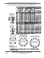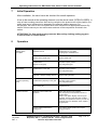
1
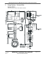
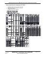
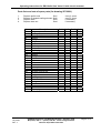
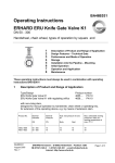
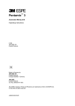
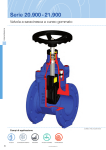
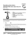
BA46E033
Operating Instructions
ERHARD ERU Knife Gate Valve K1
DN 50 - 300
Electric Actuator
1
2
3
4
5
6
7
8
9
Safety
Description of Product and Range of Application
Design Features – Technical Data
Performance and Mode of Operation
Storage
Installation into the Pipeline - Mounting
Initial Operation
Operation
Maintenance
These operating instructions must always be used in combination with operating
instructions BA01E001!
1
Safety
Access to the range of movement of the gate of ERU Knife Gate Valves with electric
actuator has to be restricted by protective devices. Effective protective devices have to
be installed by the user.
On request, we will supply suitable protective guards.
2
Description of Product and Range of Application
Type/Design
ERU Knife Gate Valve K1
ERU Knife Gate Valve K1 with regulating orifice
Product Number
4657
PN 10
4623
PN 10
Design with electric actuator
BA46E033
July 2005
Rev. 4
ERHARD-Armaturen x D-89502 Heidenheim x Postfach 1280
(07321) 320-0 (07321) 320 491 e-mail:[email protected]
Internet: http://www.erhard.de
Page 1 of 13
Operating Instructions for ERU Knife Gate Valve K1 with electric actuator
Product No.
4655, 4656
4657, 4623
Nominal
diameter
Nominal
pressure
DN
PN
50 - 300
50 – 300
10
10
Hydr. test pressure in bars
for
Body
Seat
15
15
10
10
Max. admissible
working pressure in
bars at a working
temperature of
max. 70° C
10
10
If EPDM profile seals are used for the ERU Knife Gate Valves K1, the parts of EPDM
must not get in contact with oil or grease, as the EPDM would swell.
For a recommended lubricant see section "Maintenance".
ERU Knife Gate Valves K1 of this design are suitable for "ON-OFF" operation.
For explicit regulating service, special designs have to be used, e.g. design with
regulating orifice.
BA46E033
July 2005
Rev. 4
ERHARD-Armaturen x D-89502 Heidenheim x Postfach 1280
(07321) 320-0 (07321) 320 491 e-mail:[email protected]
Internet: http://www.erhard.de
Page 2 of 13
Operating Instructions for ERU Knife Gate Valve K1 with electric actuator
3
Design Features – Technical Data
Drawing 2E 39861
ERU Knife Gate Valve K1 with electric actuator
BA46E033
July 2005
Rev. 4
ERHARD-Armaturen x D-89502 Heidenheim x Postfach 1280
(07321) 320-0 (07321) 320 491 e-mail:[email protected]
Internet: http://www.erhard.de
Page 3 of 13
Operating Instructions for ERU Knife Gate Valve K1 with electric actuator
Dimensioned table (for drawing No. 2E 39861)
1)
²)
3)
PREFERRED SERIES FOR MODULATING ACTUATORS
PREFERRED SERIES FOR STANDARD ACTUATORS
EN558-1, BASIC SERIES 20
FORMER DIN 3202, PART 3, SERIES K1
BA46E033
July 2005
Rev. 4
ERHARD-Armaturen x D-89502 Heidenheim x Postfach 1280
(07321) 320-0 (07321) 320 491 e-mail:[email protected]
Internet: http://www.erhard.de
Page 4 of 13
Operating Instructions for ERU Knife Gate Valve K1 with electric actuator
Parts lists and sets of spare parts (for drawing 2E 39861)
1.
2.
3.
4.
Replace profile seal
Replace U-shaped sealing element
Replace stem
Replace stem nut
Item
1
2
3
4
5
6
7
8
9
10
11
12
13
14
15
16
17
18
19
20
21
22
23
24
25
26
27
28
29
BA46E033
July 2005
Rev. 4
Description
Body component
Sealing element
Hexagon bolt
Washer
Hexagon nut
Gate
Profile seal
Guide tape
Compressor
Taper plug
Cover plate
Washer
Hexagon bolt
Bush
Fork nut
Bolt
Washer
Cotter pin
Stem
Straight grooved pin
Stud bolt
Gudgeon
Bearing support
Washer
Hexagon nut
Electric multi-turn actuator
Washer
Cylindrical screw
Taper plug
Set1
Set2
Set3
Set4
every 2 years
every 5 years
if necessary
if necessary
Set1
Set2
Set3
Set4
X
X
X
X
X
X
X
X
ERHARD-Armaturen x D-89502 Heidenheim x Postfach 1280
(07321) 320-0 (07321) 320 491 e-mail:[email protected]
Internet: http://www.erhard.de
Page 5 of 13
Operating Instructions for ERU Knife Gate Valve K1 with electric actuator
4
Performance and Mode of Operation
ERU Knife Gate Valves K1 are wafer-type single-door gate valves with short face-toface dimension. A special type of these valves, e.g. with regulating orifice, is also
suitable for regulating purposes. The solid gate slides in a long gate guide between
two body components. It seals on its periphery against a rubber-resilient, steelreinforced, enclosed U-shaped sealing element. Where the gate leaves the body,
tightness to the outside is ensured by a resiliently prestressed profile seal which can
be readjusted. For reducing wear and tear of the profile seal and the actuating
elements the prestress can be reduced to the dimension required for the actual
operating pressure.
The Gate Valves were tested for tightness and resistance to DIN EN12266 and
DIN EN1074 at the manufacturer's plant. They are designed for flow acting from any
direction.
ERU Knife Gate Valves K1 are disconnected in a travel-dependent manner in closing
and opening directions. The limit positions "OPEN" and "CLOSED" are signalled by
the travel switches. Running against or jamming at the upper mechanical stop of the
valve due to motor after-running is avoided. The torque switches serve as safety
switches in opening and closing directions.
ERU Knife Gate Valves K1 are switched in a travel dependent manner in closing and
opening directions.
4.1
Retrofitting of an Electric Multi-Turn Actuator
If the valve is supplied without incorporated electric actuator, the torque and travel
switches have to be set as follows after mounting the electric actuator:
4.1.1. Move the valve manually in central position and check the direction of rotation of
the motor by means of short switching impulses - if necessary, change the
poles of the motor connection. The valve closes when turning the handwheel in
clockwise direction.
4.1.2. Set the torque switches to the torques specified in the enclosed drawings.
4.1.3. Move the valve manually in open position against the upper mechanical limit
stop. Then, move the handwheel by 10 turns in closing direction and adjust the
"OPEN" travel switch.
4.1.4. Move the valve manually in closed position and adjust the "CLOSED" travel
switch.
BA46E033
July 2005
Rev. 4
ERHARD-Armaturen x D-89502 Heidenheim x Postfach 1280
(07321) 320-0 (07321) 320 491 e-mail:[email protected]
Internet: http://www.erhard.de
Page 6 of 13
Operating Instructions for ERU Knife Gate Valve K1 with electric actuator
Electrical connection has to be effected according to Operating Instructions as well
as wiring and terminal diagrams of the electric actuator's manufacturer (travel,
torque and thermal switches, heating, motor). Before installation, the insulating
resistance of the motor must be measured. If it is lower than 500 K-ohms, this
shows that the winding is moist. The motor has to be removed in order to be dried
up and it must be heated by means of a hot-air fan or in a heating chamber: max.
admissible temperature 100°C.
4.2
Commissioning of the Electric Actuator
4.2.1. Move the ERU Knife Gate Valve K1 manually to central position.
4.2.2.
Check the gate movement and thus the direction of rotation of the actuator by
short electrical starting.
+
Valve is closing = CLOCKWISE direction of actuator rotation
Valve is opening = ANTI-CLOCKWISE direction of actuator rotation
4.2.3
In case of wrong direction of rotation, change poles of motor connection.
4.2.4
Check direction of rotation by short electrical starting.
4.2.5
Check correct switching sequence of the torque switches in "Open-Close"
direction by manual operation.
4.2.6.
Change poles if necessary.
4.2.7.
Move the valve over the whole travel only if the direction of rotation for closing
the valve is CLOCKWISE.
+ In case of wrong direction of rotation, travel and torque switches are
ineffective!
BA46E033
July 2005
Rev. 4
ERHARD-Armaturen x D-89502 Heidenheim x Postfach 1280
(07321) 320-0 (07321) 320 491 e-mail:[email protected]
Internet: http://www.erhard.de
Page 7 of 13
Operating Instructions for ERU Knife Gate Valve K1 with electric actuator
4.3 Jogging Operation and Manual Emergency Operation
Note: before start-up spindle and spindle nut are to be greased. (recommended
lubricant see section “Maintenance”)
Attention:
If a foreign body is jammed in when operating the valve, the torque switch for the
corresponding direction responds and switches off the motor.
The time lag between response of the torque switch and disconnection of the motor
from the network depends on the signal delay. If another closing order is given in the
original direction, without having moved the valve sufficiently in the opposite direction,
the torque will increase. If this procedure is repeated several times, the torque will
accumulate. The valve and its operating elements are not designed for such an
emergency and might be damaged.
+ We explicitly draw your attention to the fact that such "jogging operation" is
inadmissible.
Jogging operating is admissible under the following conditions:
If the torque switch responds in intermediate position, the valve must first be moved in
the opposite direction until the torque switch completley returns to its original position.
Only now the valve may be moved again in the direction in which the disturbance
occurred. Proceeding this way, you will obtain torques corresponding to the torques
set at the torque switch. Moreover, the foreign matter can come off and be flushed out
of the seating zone.
Operation by emergency handwheel:
If the valve is operated by means of the handwheel of the electric actuator, the torque
switches do not provide any safety function.
If a foreign body is jammed with the valve being in intermedite position,
excessive operating force - particularly in case of high gear reduction - might be
damaging to the drive components. Therefore, we draw your attention to the
following fact:
If any resistance is detected during emergency handwheel operation, some turns
must be made in the opposite direction before the handwheel is turned again in the
direction in which the disturbance occurred (flush out the foreign body).
Continue operation with utmost care, in no case using excessive force. If need be,
repeat flushing operation.
BA46E033
July 2005
Rev. 4
ERHARD-Armaturen x D-89502 Heidenheim x Postfach 1280
(07321) 320-0 (07321) 320 491 e-mail:[email protected]
Internet: http://www.erhard.de
Page 8 of 13
Operating Instructions for ERU Knife Gate Valve K1 with electric actuator
5
Storage
Store ERU Knife Gate Valves K1 in their closed position. Rubber-coated
components, as e.g. the sealing element between the body parts, have to be
protected against direct solar radiation. Avoid the effects of radiant heat, e.g. from
heaters.
6
Installation into the Pipeline
Remove all packing material from the valve. Prior to installation, check the pipeline for
impurities and foreign bodies and clean it if necessary.
+ There must be free access all around the valve for operation and
maintenance.
In case of flow media containing solid matters as e.g. sand etc. and installation into
horizontal pipelines the stem or the piston rod should not be installed with an
inclination of more than 30º towards the horizontal. Thus, free flushing of the travel
range of the gate is possible.
In case of deviating installation positions, especially with suspended stem or piston
rod, deposits around the gate have to be expected. This could lead to mal-functions
which increase maintenance work.
During installation of the valve, the distance between the pipe flanges should exceed
the valve face-to-face dimension by at least 20 mm. Thus, the raised faces will not be
damaged and the gaskets can be inserted. Steel-reinforced rubber seals to DIN 2690
are recommended for use as flange gaskets, for slip-on flanges they are absolutely
necessary (consider resistance to flow medium and temperature).
The mating pipe flanges must be plain-parallel and concentric.
Tighten the connecting bolts evenly (without distortion) and crosswise. The pipeline
mustn't by any means be pulled up to the valve.
If the distance between the flanges is too large for the valve, use thicker gaskets to
cover the difference.
BA46E033
July 2005
Rev. 4
ERHARD-Armaturen x D-89502 Heidenheim x Postfach 1280
(07321) 320-0 (07321) 320 491 e-mail:[email protected]
Internet: http://www.erhard.de
Page 9 of 13
Operating Instructions for ERU Knife Gate Valve K1 with electric actuator
ERU Knife Gate Valves K1 are
- clamped between two flanges of the pipeline (wafer type) or
- screwed to the end flange of the pipeline as end-of-line valves.
The screwed connection with the pipeline is made from flange to flange by means of
bolts in the through-going holes. For the threaded blind holes the screwed connection
is made by means of stud bolts or bolts in the body components.
It is possible to roughly fasten the valve by means of the threaded holes.
The necessary connecting elements for the corresponding installation position are
shown in drawing No. 4E127 920.
BA46E033
July 2005
Rev. 4
ERHARD-Armaturen x D-89502 Heidenheim x Postfach 1280
(07321) 320-0 (07321) 320 491 e-mail:[email protected]
Internet: http://www.erhard.de
Page 10 of 13
Operating Instructions for ERU Knife Gate Valve K1 with electric actuator
Connecting elements for flange connection (to drawing 4E127920)
BA46E033
July 2005
Rev. 4
ERHARD-Armaturen x D-89502 Heidenheim x Postfach 1280
(07321) 320-0 (07321) 320 491 e-mail:[email protected]
Internet: http://www.erhard.de
Page 11 of 13
Operating Instructions for ERU Knife Gate Valve K1 with electric actuator
7
Initial Operation
After installation, the valve has to be checked for smooth operation.
It has to be moved at the operating element over the whole travel (OPEN-CLOSED). In
case of lower working pressures, after having carried out the pressure test of the pipeline, the
profile seal can be released to be adapted to the effective working pressure. For
this purpose, the bolts on the cover plate have to be loosened in an appropriate manner. By
means of this measure you can reduce wear and tear of the components involved in the
motion.
ATTENTION! The flow medium may penetrate. Wear safety clothing (safety goggles)
in case of toxic or caustic media.
8
Operation
Trouble
Possible Causes
Remedy
Leakage at the
cover plate
Prestress too low
Readjustment of cover plate
see paragraph “9 Maintenance“
Wearing of the profile seal
Replace profile seal
Contamination
(deposit on the gate)
With valve in open position:
clean and grease gate
Contamination of the gate
With valve in open position:
clean and grease gate
Defective U-shaped sealing element
Replace sealing element
Contamination (deposit) on the gate
With valve in open position:
clean and grease gate
Stem running dry
Regrease thread
Residues of flow medium are
hardened
Relieve pipe section from pressure.
Clean and grease all accessible surfaces of
gate and stem.
Slacken cover plate. Slightly unscrew upper
body bolts. Knock on the valve with a rubber
mallet trying to operate the valve. If you are not
successful: remove, dismantle, clean, replace
damaged parts.
Foreign bodies jammed in the
seating zone
Move valve in OPEN position and repeat
closing procedure
Seat leakage
Excessive operating
forces
Operation blocked
BA46E033
July 2005
Rev. 4
ERHARD-Armaturen x D-89502 Heidenheim x Postfach 1280
(07321) 320-0 (07321) 320 491 e-mail:[email protected]
Internet: http://www.erhard.de
Page 12 of 13
Operating Instructions for ERU Knife Gate Valve K1 with electric actuator
9
Maintenance
For inspection or repair, the valve – or parts thereof - must not be removed unless the
pipe section in which the valve is installed has been isolated and made pressureless. If
work is carried out in the vicinity of the valves, which leads to soiling (concrete work,
masonry, painting, sandblasting and the like), the valves must be covered effectively.
ERU Knife Gate Valves K1 have to be moved regularly at short intervals (every half
year) over the whole travel (OPEN-CLOSED). Depending on the flow medium and the
local conditions at the site of application, the maintenance interval must be reduced or
may be extended. If the profile seal is found to be untight, retighten the hexagon bolts
of the cover plate evenly. If it is no longer possible to retighten the cover plate, replace
the sealing elements.
Check gate and stem regularly for contaminations, clean them if necessary and treat
them with lubricant (rub in a thin layer).
Recommended lubricant:
KLÜBERSYNTH VR69-252
company Klüber Lubrication, Munich
Spare parts and wearing parts according to: drawing 2E 39861
BA46E033
July 2005
Rev. 4
ERHARD-Armaturen x D-89502 Heidenheim x Postfach 1280
(07321) 320-0 (07321) 320 491 e-mail:[email protected]
Internet: http://www.erhard.de
Page 13 of 13