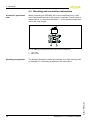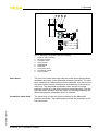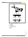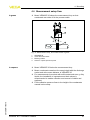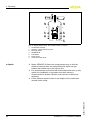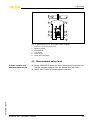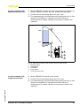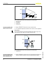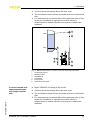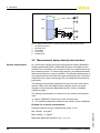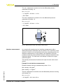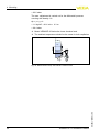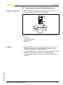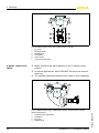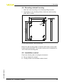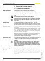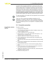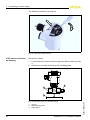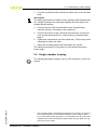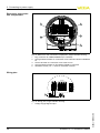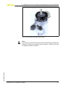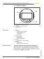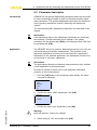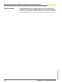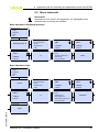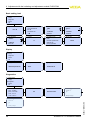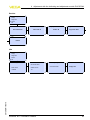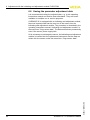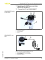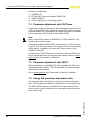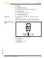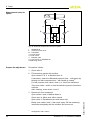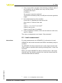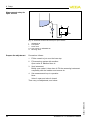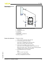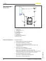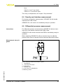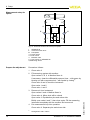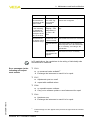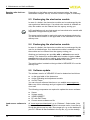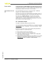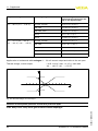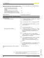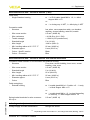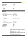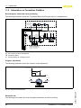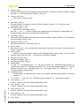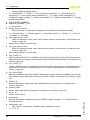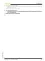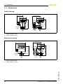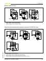
1
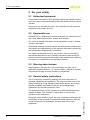
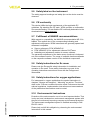
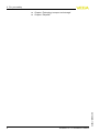
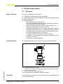
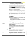
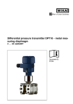
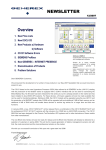
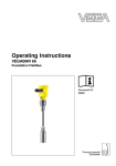
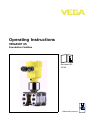
Operating Instructions
VEGADIF 65
Foundation Fieldbus
Document ID:
36130
Differential pressure
Contents
Contents
1
About this document
1.1
1.2
1.3
2
.
.
.
.
.
.
.
.
.
.
.
.
.
.
.
.
.
.
.
.
.
.
.
.
.
.
.
.
.
.
..
..
..
..
..
..
..
..
..
..
6
6
6
6
7
7
7
7
7
7
.
.
.
.
.
.
.
.
.
.
.
.
.
.
.
.
.
.
.
.
.
.
.
.
..
..
..
..
9
10
14
14
General instructions to use the instrument . . . . . . . . .
Instructions for oxygen and ultra-pure gas applications.
Mounting and connection instructions . . . . . . . . . . . .
Measurement setup flow . . . . . . . . . . . . . . . . . . . . . .
Measurement setup level . . . . . . . . . . . . . . . . . . . . .
Measurement setup density and interface . . . . . . . . .
Measurement setup differential pressure . . . . . . . . . .
Mounting external housing . . . . . . . . . . . . . . . . . . . .
Installation control. . . . . . . . . . . . . . . . . . . . . . . . . . .
16
17
18
21
23
28
31
33
33
Structure . . . . . . . . . . . . . . . . . .
Principle of operation . . . . . . . . .
Operation. . . . . . . . . . . . . . . . . .
Packaging, transport and storage
.
.
.
.
.
.
.
.
.
.
.
.
.
.
.
.
.
.
.
.
.
.
.
.
.
.
.
.
Preparing the connection . . . . . . . .
Connection procedure. . . . . . . . . . .
Single chamber housing . . . . . . . . .
Double chamber housing . . . . . . . .
Double chamber housing Ex d . . . .
Version IP 66/IP 68, 1 bar . . . . . . . .
External housing with version IP 68 .
Switch on phase. . . . . . . . . . . . . . .
.
.
.
.
.
.
.
.
.
.
.
.
.
.
.
.
.
.
.
.
.
.
.
.
.
.
.
.
.
.
.
.
.
.
.
.
.
.
.
.
.
.
.
.
.
.
.
.
.
.
.
.
.
.
.
.
.
.
.
.
.
.
.
.
.
.
.
.
.
.
.
.
.
.
.
.
.
.
.
.
.
.
.
.
.
.
.
.
..
..
..
..
..
..
..
..
34
35
37
39
40
41
41
42
Short description . . . . . . . . . . . . . . . . . . . . . . . . . . .
Insert indicating and adjustment module. . . . . . . . . . .
Adjustment system . . . . . . . . . . . . . . . . . . . . . . . . . .
44
44
46
VEGADIF 65 • Foundation Fieldbus
36130-EN-110510
Adjustment with the indicating and adjustment module
PLICSCOM
6.1
6.2
6.3
2
.
.
.
.
.
.
.
.
.
.
Connecting to power supply
5.1
5.2
5.3
5.4
5.5
5.6
5.7
5.8
6
.
.
.
.
.
.
.
.
.
.
Mounting
4.1
4.2
4.3
4.4
4.5
4.6
4.7
4.8
4.9
5
.
.
.
.
.
.
.
.
.
.
Authorised personnel . . . . . . . . . . . . . . . .
Appropriate use . . . . . . . . . . . . . . . . . . . .
Warning about misuse . . . . . . . . . . . . . . .
General safety instructions . . . . . . . . . . . .
Safety label on the instrument . . . . . . . . . .
CE conformity . . . . . . . . . . . . . . . . . . . . .
Fulfillment of NAMUR recommendations . .
Safety instructions for Ex areas . . . . . . . . .
Safety instructions for oxygen applications .
Environmental instructions. . . . . . . . . . . . .
Product description
3.1
3.2
3.3
3.4
4
5
5
5
For your safety
2.1
2.2
2.3
2.4
2.5
2.6
2.7
2.8
2.9
2.10
3
Function. . . . . . . . . . . . . . . . . . . . . . . . . . . . . . . . . .
Target group . . . . . . . . . . . . . . . . . . . . . . . . . . . . . .
Symbolism used. . . . . . . . . . . . . . . . . . . . . . . . . . . .
Contents
6.4
6.5
6.6
7
Connect the PC via VEGACONNECT .
Parameter adjustment with PACTware .
Parameter adjustment with AMS™ . . .
Saving the parameter adjustment data .
.
.
.
.
.
.
.
.
.
.
.
.
.
.
.
.
.
.
.
.
.
.
.
.
.
.
.
.
.
.
.
.
.
.
.
.
..
..
..
..
61
62
62
62
Select the mode . . . . . . . . . . . . . . .
Flow measurement . . . . . . . . . . . . .
Level measurement . . . . . . . . . . . .
Density and interface measurement .
Differential pressure measurement. .
Setup
.
.
.
.
.
.
.
.
.
.
.
.
.
.
.
.
.
.
.
.
.
.
.
.
.
.
.
.
.
.
.
.
.
.
.
.
.
.
.
.
.
.
.
.
.
.
.
.
.
.
.
.
.
.
.
..
..
..
..
..
63
63
65
69
69
.
.
.
.
.
.
.
.
.
.
.
.
.
.
.
.
.
.
.
.
.
.
.
.
.
.
.
.
.
.
.
.
.
.
.
.
.
.
.
.
.
.
.
.
.
.
.
.
.
.
.
.
.
.
.
.
.
.
.
.
.
.
.
.
.
.
..
..
..
..
..
..
72
72
74
74
74
75
10.1 Dismounting steps . . . . . . . . . . . . . . . . . . . . . . . . . .
10.2 Disposal . . . . . . . . . . . . . . . . . . . . . . . . . . . . . . . . .
76
76
8.1
8.2
8.3
8.4
8.5
9
47
57
60
Operating with PACTware and other adjustment programs
7.1
7.2
7.3
7.4
8
Parameter description . . . . . . . . . . . . . . . . . . . . . . . .
Menu schematic . . . . . . . . . . . . . . . . . . . . . . . . . . . .
Saving the parameter adjustment data . . . . . . . . . . . .
Maintenance and fault rectification
9.1
9.2
9.3
9.4
9.5
9.6
Maintenance . . . . . . . . . .
Fault rectification . . . . . . .
Exchanging the electronics
Exchanging the electronics
Software update . . . . . . . .
Instrument repair . . . . . . .
......
......
module
module
......
......
.
.
.
.
.
.
10 Dismounting
11 Supplement
11.1 Technical data . . . . . . . . . . . . . . . . . . . . . . . . . . . . .
11.2 Information on Foundation Fieldbus . . . . . . . . . . . . . .
11.3 Dimensions . . . . . . . . . . . . . . . . . . . . . . . . . . . . . . .
77
90
94
Supplementary documentation
Information:
Supplementary documents appropriate to the ordered version come
with the delivery. You can find them listed in chapter "Product
description".
36130-EN-110510
Instructions manuals for accessories and replacement parts
Tip:
To ensure reliable setup and operation of your instrument, we offer
accessories and replacement parts. The corresponding instructions
manuals are:
l
l
l
27720 - External indication VEGADIS 61
34296 - Protective cover
36132 - Electronics module DF60 for VEGADIF 65
VEGADIF 65 • Foundation Fieldbus
3
Contents
36130-EN-110510
Information:
Editing status: 2011-05-09
4
VEGADIF 65 • Foundation Fieldbus
1 About this document
1 About this document
1.1 Function
This operating instructions manual provides all the information you
need for mounting, connection and setup as well as important
instructions for maintenance and fault rectification. Please read this
information before putting the instrument into operation and keep this
manual accessible in the immediate vicinity of the device.
1.2 Target group
This operating instructions manual is directed to trained qualified
personnel. The contents of this manual should be made available to
these personnel and put into practice by them.
1.3 Symbolism used
Information, tip, note
This symbol indicates helpful additional information.
Caution: If this warning is ignored, faults or malfunctions can
result.
Warning: If this warning is ignored, injury to persons and/or serious
damage to the instrument can result.
Danger: If this warning is ignored, serious injury to persons and/or
destruction of the instrument can result.
Ex applications
This symbol indicates special instructions for Ex applications.
l
à
Action
This arrow indicates a single action.
Sequence
Numbers set in front indicate successive steps in a procedure.
36130-EN-110510
1
List
The dot set in front indicates a list with no implied sequence.
VEGADIF 65 • Foundation Fieldbus
5
2 For your safety
2 For your safety
2.1 Authorised personnel
All operations described in this operating instructions manual must be
carried out only by trained specialist personnel authorised by the plant
operator.
During work on and with the device the required personal protective
equipment must always be worn.
2.2 Appropriate use
VEGADIF 65 is a differential pressure transmitter for measurement of
flow, level, differential pressure, density and interface.
You can find detailed information on the application range in chapter
"Product description".
Operational reliability is ensured only if the instrument is properly used
according to the specifications in the operating instructions manual as
well as possible supplementary instructions.
For safety and warranty reasons, any invasive work on the device
beyond that described in the operating instructions manual may be
carried out only by personnel authorised by the manufacturer. Arbitrary
conversions or modifications are explicitly forbidden.
2.3 Warning about misuse
Inappropriate or incorrect use of the instrument can give rise to
application-specific hazards, e.g. vessel overfill or damage to system
components through incorrect mounting or adjustment.
2.4 General safety instructions
This is a high-tech instrument requiring the strict observance of
standard regulations and guidelines. The user must take note of the
safety instructions in this operating instructions manual, the countryspecific installation standards as well as all prevailing safety
regulations and accident prevention rules.
The instrument must only be operated in a technically flawless and
reliable condition. The operator is responsible for trouble-free
operation of the instrument.
6
VEGADIF 65 • Foundation Fieldbus
36130-EN-110510
During the entire duration of use, the user is obliged to determine the
compliance of the necessary occupational safety measures with the
current valid rules and regulations and also take note of new
regulations.
2 For your safety
2.5 Safety label on the instrument
The safety approval markings and safety tips on the device must be
observed.
2.6 CE conformity
This device fulfills the legal requirements of the applicable EC
guidelines. By attaching the CE mark, VEGA provides a confirmation
of successful testing. You can find the CE conformity declaration in the
download area of www.vega.com.
2.7 Fulfillment of NAMUR recommendations
With respect to compatibility, the NAMUR recommendation NE 53 is
fulfilled. This applies also to the corresponding indicating and
adjustment components. VEGA instruments are generally upward and
downward compatible.
l
l
l
Sensor software to DTM VEGADIF 65
DTM VEGADIF 65 for adjustment software PACTware
Indicating and adjustment module for sensor software
The parameter adjustment of the basic sensor functions is independent of the software version. The range of available functions depends
on the respective software version of the individual components.
2.8 Safety instructions for Ex areas
Please note the Ex-specific safety information for installation and
operation in Ex areas. These safety instructions are part of the
operating instructions manual and come with the Ex-approved
instruments.
2.9 Safety instructions for oxygen applications
For instruments in oxygen applications the special instructions in
chapters "Storage and transport", "Mounting" as well as "Technical
data" under "Process conditions"must be noted. Furthermore the valid
national regulations, implementation instructions and memorandums
of the professional assocations must be noted.
36130-EN-110510
2.10 Environmental instructions
Protection of the environment is one of our most important duties. That
is why we have introduced an environment management system with
the goal of continuously improving company environmental protection.
The environment management system is certified according to DIN
EN ISO 14001.
Please help us fulfil this obligation by observing the environmental
instructions in this manual:
VEGADIF 65 • Foundation Fieldbus
7
2 For your safety
l
l
Chapter "Packaging, transport and storage"
Chapter "Disposal"
36130-EN-110510
8
VEGADIF 65 • Foundation Fieldbus
3 Product description
3 Product description
3.1 Structure
Scope of delivery
The scope of delivery encompasses:
l
l
l
l
Constituent parts
VEGADIF 65 differential pressure transmitter
Depending on the version ventilation valves and/or closing screws
Optional accessory
Documentation
- this operating instructions manual
- Operating instructions manual 27835 "Indicating and adjustment module PLICSCOM" (optional)
- Supplementary instructions manual 31708 "Heating for indicating and adjustment module" (optional)
- Operating instructions 36133 "Chemical seal CSB" (optional)
- Operating instructions 36134 "Chemical seal CSS" (optional)
- Supplementary instructions manual "Plug connector for continuously measuring sensors" (optional)
- Ex-specific "Safety instructions" (with Ex versions)
- Certificate "Oil and grease-free for oxygen applications" (with
respective versions)
- if necessary, further certificates
The following illustration shows the components of VEGADIF 65:
1
2
3
+ –
36130-EN-110510
Fig. 1: VEGADIF 65 in basic version
1
2
3
Housing cover, optionally with integrated indicating and adjustment module
Housing with electronics
Process component with measuring cell
The components are available in different versions.
Type label
The type label contains the most important data for identification and
use of the instrument:
VEGADIF 65 • Foundation Fieldbus
9
3 Product description
l
l
l
l
l
l
l
Instrument type
Article number instrument
Ex approval
Technical data: Measuring range, process pressure, process
temperature, signal output, voltage supply, protection, protection
class
Order number, serial number instrument
Hardware and software version
Article numbers, documentation
With the serial number, you can access the delivery data of the
instrument via www.vega.com, "VEGA Tools" and "serial number
search". In addition to the type label outside, you can also find the
serial number on the inside of the instrument.
3.2 Principle of operation
Application area
VEGADIF 65 is a differential pressure transmitter for measurement of
flow, level, differential pressure, density and interface. Measured
products are gases, vapours and liquids.
Flow measurement
+
Q ~ ∆p
p1
Q
+
–
p2
Q ~ ∆p
–
p1
p2
Q
1
2
Fig. 2: Flow measurement with VEGADIF 65 and DP flow element, Q = flow, Δp =
differential pressure, Δp = p1 - p2
1
2
Orifice
Pitot tube
36130-EN-110510
10
VEGADIF 65 • Foundation Fieldbus
3 Product description
Level measurement
–
∆p
h= ρ g
h
–
+
+ –
+
2
1
3
Fig. 3: Level measurement with VEGADIF 65. Δp = differential pressure, ρ =
density of the medium, g = acceleration of gravity
1
2
3
Basic version with effective pressure lines
Version with flange chemical seal
Version with capillaries and cell chemical seals
Differential pressure measurement
2
+
1
Fig. 4: Differential pressure measurement with VEGADIF 65
Filter
VEGADIF 65
36130-EN-110510
1
2
VEGADIF 65 • Foundation Fieldbus
11
3 Product description
Density measurement
–
∆p
h g
=
h
+
1
Fig. 5: Density measurement with VEGADIF 65, h = defined mounting distance,
Δp = differential pressure, ρ = density of the medium, g = acceleration of gravity
1
VEGADIF 65
Interface measurement
–
2
+
h
3
1
Fig. 6: Interface measurement with VEGADIF 65
1
2
3
Functional principle
VEGADIF 65
Liquid with highest density
Liquid with lowest density
A metallic measuring cell is used as sensor element. The process
pressures are transmitted via the separating diaphragms and filling oils
to a resistance measuring bridge (semi-conductor technology).
12
VEGADIF 65 • Foundation Fieldbus
36130-EN-110510
The difference of the existing pressures generates a change of the
bridge voltage. This change is measured, further processed and
converted into a corresponding output signal.
3 Product description
For connection to the processe, the marking "+" and "-" on the process
component in chapter "Mounting and connection instructions" must
hence be noted. The pressure effective on "+" goes positive, the
effective pressure on "-" goes negative into the calculation of the
pressure difference.
The configuration of the measuring cells differs depending on the
measuring range:
1
2
p1
3
4
p2
5
Fig. 7: Metallic measuring cell 10 mbar and 30 mbar - p1 and p2 process
pressures
1
2
3
4
5
Measuring element
Silicone diaphragm
Separating diaphragm
Filling oil
Integrated overvoltage arrester
1
p1
2
3
4
p2
Fig. 8: Metallic measuring cell from 100 mbar - p1 and p2 process pressures
36130-EN-110510
1
2
3
4
Power supply and bus
communication
Measuring element
Overload diaphragm/Middle diaphragm
Filling oil
Separating diaphragm
Power is supplied via the H1 Fieldbus. A two-wire cable according to
Fieldbus specification serves as carrier of both power and digital data
for multiple sensors. This cable can be operated in two versions:
l
via an H1 interface card in the control system and additional power
supply
VEGADIF 65 • Foundation Fieldbus
13
3 Product description
l
DD/CFF
via a Linking device with HSE (High speed Ethernet) and
additional power supply according to IEC 61158-2
The DD (Device Descriptions) and CFF (capability files) necessary for
planning and configuration of your FF (Foundation Fieldbus) communication network are available in the download area of the VEGA
homepage www.vega.com under "Services - Downloads - Software Foundation Fieldbus". The appropriate certificates are also available
there. A CD with the appropriate files and certificates can be ordered
via e-mail under [email protected] or by phone from one of the VEGA
agencies under the order number "DRIVER.S".
The backlight of the indicating and adjustment module is powered by
the sensor. Prerequisite is a certain level of operating voltage.
The data for power supply are specified in chapter "Technical data".
The optional heating requires its own operating voltage. You can find
details in the supplementary instructions manual "Heating for indicating and adjustment module".
This function is generally not available for approved instruments.
3.3 Operation
The instrument can be adjusted with the following adjustment media:
l
l
l
with indicating and adjustment module
with the suitable VEGA DTM in conjunction with an adjustment
software according to the FDT/DTM standard, e.g. PACTware and
PC
a configuration tool
3.4 Packaging, transport and storage
Packaging
Your instrument was protected by packaging during transport. Its
capacity to handle normal loads during transport is assured by a test
according to DIN EN 24180.
The packaging of standard instruments consists of environmentfriendly, recyclable cardboard. For special versions, PE foam or PE foil
is also used. Dispose of the packaging material via specialised
recycling companies.
Caution:
Instruments for oxygen applications are sealed in PE foil and provided
with a label "Oxygen! Use no Oil". Remove this foil just before
mounting the instrument! See instruction under "Mounting".
14
Transport must be carried out under consideration of the notes on the
transport packaging. Nonobservance of these instructions can cause
damage to the device.
VEGADIF 65 • Foundation Fieldbus
36130-EN-110510
Transport
3 Product description
Transport inspection
The delivery must be checked for completeness and possible transit
damage immediately at receipt. Ascertained transit damage or
concealed defects must be appropriately dealt with.
Storage
Up to the time of installation, the packages must be left closed and
stored according to the orientation and storage markings on the
outside.
Unless otherwise indicated, the packages must be stored only under
the following conditions:
Storage and transport
temperature
l
l
l
l
l
Not in the open
Dry and dust free
Not exposed to corrosive media
Protected against solar radiation
Avoiding mechanical shock and vibration
l
Storage and transport temperature see chapter "Supplement Technical data - Ambient conditions"
Relative humidity 20 … 85 %
36130-EN-110510
l
VEGADIF 65 • Foundation Fieldbus
15
4 Mounting
4 Mounting
4.1 General instructions to use the instrument
Suitability for the process conditions
Make sure that all parts of the instrument exposed to the process, in
particular the sensor element, process seal and process fitting, are
suitable for the existing process conditions. These include above all
the process pressure, process temperature as well as the chemical
properties of the medium.
You can find the specifications in chapter "Technical data" or on the
type label.
Moisture
Use the recommended cables (see chapter "Connecting to power
supply") and tighten the cable gland.
You can give the instrument additional protection against moisture
penetration by leading the connection cable downward in front of the
cable entry. Rain and condensation water can thus drain off. This
applies mainly to outdoor mounting as well as installation in areas
where high humidity is expected (e.g. through cleaning processes) or
on cooled or heated vessels.
Ventilation
The ventilation for the electronics housing is realised via a filter
element in the vicinity of the cable glands.
1
1
1
2
2
2
2
1
Fig. 9: Position of the filter element with single and double chamber housing
Filter element for ventilation of the electronics housing
Blind stopper
Information:
Make sure that the filter element is always free of buildup during
operation. A high-pressure cleaner must not be used for cleaning.
16
VEGADIF 65 • Foundation Fieldbus
36130-EN-110510
1
2
4 Mounting
Effective pressure
transmitter
DP flow elements are calculated for certain pipeline and operating
data. Therefore, check the pipeline data before installation at the
measuring point and compare the measurement loop number.
Detailed instructions for mounting the DP flow element are stated in
DIN EN ISO 5167 as well as in the instrument documentation from the
respective manufacturer.
Effective pressure lines
You will find general recommendations for the installation of effective
pressure lines in DIN 19210 "Effective pressure lines for flow systems"
or the corresponding national or international standards. When
installing effective pressure lines outdoors, consider applying suitable
anti-freeze protection, e.g. tube heating. Install effective pressure lines
with a monotonic downward slope of at least 10 %.
Vibrations
In case of strong vibrations at the application position, the instrument
version with external electronics should be used.
Temperature limits
Higher process temperatures often mean also higher ambient
temperatures for electronics and connection cable. Make sure that the
upper temperature limits stated in chapter "Technical data" for the
environment of the electronics housing and connection cable are not
exceeded.
4.2 Instructions for oxygen and ultra-pure gas
applications
Oxygen applications
Oxygen and other gases can be explosive when brought into contact
with oils, grease and plastics, so the following measures must also be
taken:
l
l
All components of the plant, such as e.g. measuring instruments
must be cleaned according to the requirements of BAM
(DIN 19247)
Depending on the seal material, certain temperatures and
pressures must not be exceeded in oxygen applications, see
chapter "Technical data"
36130-EN-110510
Danger:
Instruments for oxygen applications must be unpacked just before
mounting. After removing the protective cover of the process fitting, the
label "O₂" will be visible on the process fitting. Penetration of oil,
grease and dirt should be avoided. Danger of explosion!
Pure gas applications
We also offer oil and grease free instruments for special applications
such as e.g. ultra-pure gas. There are no special restrictions with
respect to the process conditions.
VEGADIF 65 • Foundation Fieldbus
17
4 Mounting
4.3 Mounting and connection instructions
Connection plus/minus
side
When connecting the VEGADIF 65 to the measurement loop, take
note of the plus/minus side of the process component. The plus side is
marked with a "+", the minus side with a "-" on the process component
next to the oval flanges.
+ –
1
2
Fig. 10: Marking for plus/minus side on the process component
1
2
Mounting arrangement
Plus side
Minus side
The following illustration shows the elements for a tube mounting and
an example for a mounting arrangement with valve block.
36130-EN-110510
18
VEGADIF 65 • Foundation Fieldbus
4 Mounting
1 2
3
4
5
6
7
8
9
Fig. 11: Mounting arrangement with tube mounting
1
2
3
4
5
6
7
8
9
Strap for tube mounting
Mounting bracket
Ventilation valve
Fixing screws
VEGADIF 65
PTFE seal
5-fold valve block
Oval flange adapter
Fixing screws
The use of the valve block with inlet and outlet valves allows simple
installation and setup of the differential pressure transmitter. The valve
block separates the differential pressure transmitter from the process
side and enables simple maintenance and checking of the measurement loop. The integrated equalization valve ensures the same
pressure conditions on the plus and minus side during setup. The fivefold valve block contains also two valves for checking/ventilating the
differential pressure transmitter after it is installed.
Connection valve block
The valve block is used for direct connection to the differential
pressure transmitter. The following figure shows the connection of a 5fold valve block.
36130-EN-110510
Valve block
VEGADIF 65 • Foundation Fieldbus
19
4 Mounting
A
7
A:
8
3 1
2
5
9
2
4 6
3
4
5
1
7
9 8
2
6
Fig. 12: Connection of a 5-fold valve block
1
2
3
4
5
6
7
8
9
Process fitting
Process fitting
Check/Ventilate
Check/Ventilate
Valve for checking/ventilating
Valve for checking/ventilating
Inlet valve
Inlet valve
Breather valve
36130-EN-110510
20
VEGADIF 65 • Foundation Fieldbus
4 Mounting
4.4 Measurement setup flow
In gases
à Mount VEGADIF 65 above the measurement loop so that
condensate can drain off in the process cable.
1
2
3
+
–
4
Fig. 13: Measurement setup, flow measurement in gases
1
2
3
4
In vapours
VEGADIF 65
Three-fold valve block
Blocking valves
Orifice or impact pressure probe
à Mount VEGADIF 65 below the measurement loop
à Mount condensate vessels at the same height with the discharge
socket and at the same distance to VEGADIF 65
à For measurements in products with solid content such as e.g. dirty
liquids, the installation of separators and drain valves is
recommended to enable collection and removal of debris and
sediment.
36130-EN-110510
à Fill the effective pressure lines to the height of the condensate
vessels before setup
VEGADIF 65 • Foundation Fieldbus
21
4 Mounting
1
2
3
+
3
4
–
5
5
6
6
7
Fig. 14: Measurement setup, flow measurement in vapours
1
2
3
4
5
6
7
In liquids
Condensate vessels
Orifice or impact pressure probe
Blocking valves
VEGADIF 65
Precipitator
Drain valves
Three-fold valve block
à Mount VEGADIF 65 below the measurement loop so that the
effective pressure lines are always filled with liquid and gas
bubbles can bubble up to the process line
à For measurements in products with solid content such as e.g. dirty
liquids, the installation of separators and drain valves is
recommended to enable collection and removal of debris and
sediment.
à Fill the effective pressure lines to the height of the condensate
vessels before setup
36130-EN-110510
22
VEGADIF 65 • Foundation Fieldbus
4 Mounting
1
2
+
2
3
–
4
4
5
5
6
Fig. 15: Measurement setup, flow measurement in liquids
1
2
3
4
5
6
Orifice or impact pressure probe
Blocking valves
VEGADIF 65
Precipitator
Drain valves
Three-fold valve block
4.5 Measurement setup level
In open vessels with
effective pressure line
à Mount VEGADIF 65 below the lower measurement connection so
that the effective pressure lines are always filled with liquid
36130-EN-110510
à Minus side is open to the atmospheric pressure
VEGADIF 65 • Foundation Fieldbus
23
4 Mounting
à For measurements in products with solid content such as e.g. dirty
liquids, the installation of separators and drain valves is
recommended to enable collection and removal of debris and
sediment.
patm
+
min.
patm
1
4
5
3
2
Fig. 16: Measurement setup, level measurement in the open vessel
1
2
3
4
5
In open vessels with
single chemical seal
VEGADIF 65
Minus side is open to the atmospheric pressure
Blocking valve
Precipitator
Drain valve
à Mount VEGADIF 65 directly to the vessel
à Minus side is open to the atmospheric pressure
patm
min.
1
+
+ –
2 patm
Fig. 17: Measurement setup, level measurement in the open vessel
24
VEGADIF 65
Minus side is open to the atmospheric pressure
VEGADIF 65 • Foundation Fieldbus
36130-EN-110510
1
2
4 Mounting
In closed vessels with
effective pressure lines
à Mount VEGADIF 65 below the lower measurement connection so
that the effective pressure lines are always filled with liquid
à Connect minus side always above the max. level
à For measurements in products with solid content such as e.g. dirty
liquids, the installation of separators and drain valves is
recommended to enable collection and removal of debris and
sediment.
max.
–
min.
+
1
1
2
3
3
4
4
5
Fig. 18: Measurement setup, level measurement in closed vessel
1
2
3
4
5
In closed vessels with
single chemical seal
Blocking valves
VEGADIF 65
Precipitator
Drain valves
Three-fold valve block
à Mount VEGADIF 65 directly to the vessel
à Connect minus side always above the max. level
36130-EN-110510
à For measurements in products with solid content such as e.g. dirty
liquids, the installation of separators and drain valves is
recommended to enable collection and removal of debris and
sediment.
VEGADIF 65 • Foundation Fieldbus
25
4 Mounting
1
–
max.
min.
2
+ –
+
3
4
Fig. 19: Measurement setup, level measurement in closed vessel
1
2
3
4
In closed vessels with
double chemical seal
Blocking valve
Precipitator
Drain valve
VEGADIF 65
à Mount VEGADIF 65 below the lower chemical seal
à The ambient temperature should be the same for both capillaries
Information:
Level measurement is only ensured between the upper edge of the
lower and the lower edge of the upper chemical seal.
–
max.
1
min.
+
Fig. 20: Measurement setup, level measurement in closed vessel
1
26
à Mount VEGADIF 65 below the lower measurement connection so
that the effective pressure lines are always filled with liquid
VEGADIF 65 • Foundation Fieldbus
36130-EN-110510
In closed vessels with
steam layering with effective pressure line
VEGADIF 65
4 Mounting
à Connect minus side always above the max. level
à The condensate vessel ensures a constant pressure on the minus
side
à For measurements in products with solid content such as e.g. dirty
liquids, the installation of separators and drain valves is
recommended to enable collection and removal of debris and
sediment.
–
1
max.
2
min.
+
2
3
4
5
5
6
Fig. 21: Measurement setup in closed vessel with superimposed steam
1
2
3
4
5
6
36130-EN-110510
In closed vessels with
superimposed steam
with single chemical
seal
Condensate vessel
Blocking valves
VEGADIF 65
Precipitator
Drain valves
Three-fold valve block
à Mount VEGADIF 65 directly to the vessel
à Connect minus side always above the max. level
à The condensate vessel ensures a constant pressure on the minus
side
à For measurements in products with solid content such as e.g. dirty
liquids, the installation of separators and drain valves is
recommended to enable collection and removal of debris and
sediment.
VEGADIF 65 • Foundation Fieldbus
27
4 Mounting
max.
–
1
2
min.
3
+ –
+
5
4
Fig. 22: Measurement setup in closed vessel with superimposed steam
1
2
3
4
5
Condensate vessel
Blocking valve
Precipitator
Drain valve
VEGADIF 65
4.6 Measurement setup density and interface
Density measurement
In a vessel with varying level and homogeneous density distribution,
density measurement with a differential pressure transmitter can be
realized. The connection to the vessel is made via a chemical seal on
two measuring points. To reach a high accuracy, the distance between
these points must be as big as possible. The density measurement is
only ensured with a level above the upper measuring point. If the level
drops below the upper measuring point, the density measurement is
interrupted.
This density measurement functions with open but also with closed
vessels. Make sure that small density changes cause only small
changes to the measured differential pressure. Select a suitable
measuring range.
The density measurement is carried out in the mode level measurement.
à Mount VEGADIF 65 below the lower chemical seal
à The ambient temperature should be the same for both capillaries
Example for a density measurement:
Distance between the two measurement points: 0.3 m
Min. density: 1.0 kg/dm3
Measured differential pressure: Δp = ρ • g • h
28
VEGADIF 65 • Foundation Fieldbus
36130-EN-110510
Max. density: 1.2 kg/dm3
4 Mounting
The min. adjustment is carried out for the differential pressure
measured at density 1.0:
Δp = ρ • g • h
= 1.0 kg/dm³ • 9.81m/s • 0.3 m
= 29.4 mbar
The max. adjustment is carried out for the differential pressure
measured at density 1.2:
Δp = ρ • g • h
= 1.2 kg/dm³ • 9.81m/s • 0.3 m
= 35.3 mbar
0,3 m
–
=
∆p
h g
+
Fig. 23: Measurement setup with density measurement
Interface measurement
In a vessel with varying level, an interface measurement with a
differential pressure transmitter can be realized. The connection on the
vessel is carried out via a chemical seal on two measuring points. An
interface measurement is only possible if the densities of the two
products remain the same and the interface is always between the two
measuring points. The total level must always be above the upper
measuring point.
This density measurement functions with open but also with closed
vessel.
Example for an interface measurement:
Distance between the two measurement points: 0.3 m
Min. density: 0.8 kg/dm3
36130-EN-110510
Max. density: 1.0 kg/dm3
The min. adjustment is carried out for the differential pressure occuring
with density 0.8:
Δp = ρ • g • h
= 0.8 kg/dm³ • 9.81 m/s• 0.3 m
VEGADIF 65 • Foundation Fieldbus
29
4 Mounting
= 23.5 mbar
The max. adjustment is carried out for the differential pressure
occuring with density 1.0:
Δp = ρ • g • h
= 1.0 kg/dm³ • 9.81 m/s • 0.3 m
= 29.4 mbar
à Mount VEGADIF 65 below the lower chemical seal
à The ambient temperature should be the same for both capillaries
0,3 m
0,8
1,0
–
+
1
Fig. 24: Measurement setup with interface measurement
36130-EN-110510
30
VEGADIF 65 • Foundation Fieldbus
4 Mounting
4.7 Measurement setup differential pressure
In gases and vapours
à Mount VEGADIF 65 above the measurement loop so that
condensate can drain off in the process cable.
1
2
+
3
3
4
Fig. 25: Measurement setup, differential pressure measurement in gases and
vapours
1
2
3
4
In liquids
VEGADIF 65
Three-fold valve block
Blocking valves
E.g. filter
à Mount VEGADIF 65 below the measurement loop so that the
effective pressure lines are always filled with liquid and gas
bubbles can bubble up to the process line
36130-EN-110510
à For measurements in products with solid content such as e.g. dirty
liquids, the installation of separators and drain valves is
recommended to enable collection and removal of debris and
sediment.
VEGADIF 65 • Foundation Fieldbus
31
4 Mounting
1
2
2
–
+
3
4
4
5
5
6
Fig. 26: Measurement setup, flow measurement in liquids
1
2
3
4
5
6
In gases, vapours and
liquids
E.g. filter
Blocking valves
VEGADIF 65
Precipitator
Drain valves
Three-fold valve block
à Mount chemical seal with capillaries on top or laterally on the
pipeline
à In vacuum applications: Mount VEGADIF 65 below the measurement loop
à The ambient temperature should be the same for both capillaries
2
1
2
–
+
3
4
1
2
3
4
32
Chemical seal with bolting
Capillaries
E.g. filter
VEGADIF 65
VEGADIF 65 • Foundation Fieldbus
36130-EN-110510
Fig. 27: Measurement setup, differential pressure measurement in gases,
vapours and liquids
4 Mounting
4.8 Mounting external housing
1
Mark the holes according to the following drilling template
2
Depending on the mounting surface, fasten the wall mounting
plate with 4 screws
90 mm (3.54")
70 mm (2.76")
3 mm
(0.12")
8 mm
(0.32")
93 mm (3.66")
110 mm (4.33")
mm
,5 ")
R3 0.14
(
Fig. 28: Drilling template - wall mounting plate
Mount the wall mounting plate so that the cable entry of the socket
housing points downward. The socket housing can be displaced by
180° to the wall mounting plate.
4.9 Installation control
Check the following after mounting the instrument:
Did you tighten all screws?
Closing screws and ventilation valves closed
36130-EN-110510
l
l
VEGADIF 65 • Foundation Fieldbus
33
5 Connecting to power supply
5 Connecting to power supply
5.1 Preparing the connection
Safety instructions
Always keep in mind the following safety instructions:
l
l
Connect only in the complete absence of line voltage
If overvoltage surges are expected, overvoltage arresters should
be installed according to Foundation Fieldbus specification
Tip:
We recommend VEGA overvoltage arrester B63-32.
In hazardous areas you must take note of the respective regulations,
conformity and type approval certificates of the sensors and power
supply units.
Voltage supply
The instrument requires a operating voltage of 9 … 32 V DC.
Operating voltage and the digital bus signal are carried on the same
two-wire connection cable. Power is supplied via the H1 power supply.
Connection cable
Connection is carried out with screened cable according to Fieldbus
specification.
Use cable with round cross-section. A cable outer diameter of 5 … 9 mm
(0.2 … 0.35 in) ensures the seal effect of the cable gland. If you are
using cable with a different diameter or cross-section, exchange the
seal or use a suitable cable gland.
Make sure that the entire installation is carried out according to the
Fieldbus specification. In particular, make sure that the bus is
terminated with suitable terminating resistors.
Cable gland ½ NPT
On the instrument with cable entry ½ NPT and plastic housing there is
a metallic ½" threaded insert moulded into the plastic housing.
Caution:
No grease should be used when screwing the NPT cable gland or
steel tube into the threaded insert. Standard grease can contain
additives that corrode the connection between threaded insert and
housing. This would influence the stability of the connection and the
tightness of the housing.
Cable screening and
grounding
VEGADIF 65 • Foundation Fieldbus
36130-EN-110510
34
In systems with potential equalisation, connect the cable screen
directly to ground potential at the power supply unit, in the connection
box and at the sensor. The screen in the sensor must be connected
directly to the internal ground terminal. The ground terminal outside on
the housing must be connected to the potential equalisation (low
impedance).
5 Connecting to power supply
In systems without potential equalisation, connect the cable screen
directly to ground potential at the power supply unit and at the sensor.
In the connection box or T-distributor, the screen of the short stub to
the sensor must not be connected to ground potential or to another
cable screen. The cable screens to the power supply unit and to the
next distributor must be connected to each other and also connected
to ground potential via a ceramic capacitor (e.g. 1 nF, 1500 V). Lowfrequency potential equalisation currents are thus suppressed, but the
protective effect against high frequency interference signals remains.
The total capacitance of the cable and of all capacitors must not exceed
10 nF in Ex applications.
Take note of the corresponding installation regulations for Ex
applications. In particular, make sure that no potential equalisation
currents flow over the cable screen. In case of grounding on both sides
this can be achieved by the use of a capacitor or a separate potential
equalisation.
5.2 Connection procedure
Single/Double chamber
housing
Proceed as follows:
1
Unscrew the housing cover
2
If an indicating and adjustment module is installed, remove it by
turning it slightly to the left.
3
Loosen compression nut of the cable entry
4
Remove approx. 10 cm of the cable mantle, strip approx. 1 cm
insulation from the individual wires
5
Insert the cable into the sensor through the cable entry
6
Lift the opening levers of the terminals with a screwdriver (see
following illustration)
7
Insert the wire ends into the open terminals according to the wiring
plan
8
Press down the opening levers of the terminals, you will hear the
terminal spring closing
9
Check the hold of the wires in the terminals by lightly pulling on
them
10 Connect the screen to the internal ground terminal, connect the
outer ground terminal to potential equalisation
11 Tighten the compression nut of the cable entry. The seal ring must
completely encircle the cable
36130-EN-110510
12 Screw the housing cover on
VEGADIF 65 • Foundation Fieldbus
35
5 Connecting to power supply
The electrical connection is finished.
Fig. 29: Connection steps 6 and 7
IP 68 version with external housing
Proceed as follows:
1
Loosen the four screws on the housing base with an Allen key size
4
2
Remove the housing socket from the mounting plate
3
1
2
1
2
3
36
Screws
Wall mounting plate
Cable gland
VEGADIF 65 • Foundation Fieldbus
36130-EN-110510
Fig. 30: Components of the external housing
5 Connecting to power supply
3
Loop the connection cable through the cable entry on the housing
base1)
Information:
The cable gland can be mounted in three positions each displaced by
90°. Simply exchange the cable gland against the blind plug in the
suitable thread opening.
4
Connect the wire ends as described under "Single/Double
chamber housing" according to the numbering
5
Connect the screen to the internal ground terminal, connect the
outer ground terminal above on the housing to potential equalisation
6
Tighten the compression nut of the cable entry. The seal ring must
completely encircle the cable
7
Attach the mounting plate again and tighten the screws
The electrical connection of the sensor to the external housing is
hence ready.
5.3 Single chamber housing
36130-EN-110510
The following illustrations apply to the non-Ex as well as to the Ex-ia
version.
1)
The connection cable is already preconfectioned. If necessary, shorten it to
the requested length, cut the breather capillaries clean. Remove approx.
5 cm of the cable mantle, strip approx. 1 cm insulation from the ends of the
individual wires. After shortening the cable, fasten the type plate with support back onto the cable.
VEGADIF 65 • Foundation Fieldbus
37
5 Connecting to power supply
Electronics and connection compartment
Typ:
Bus
Display
Sim.
5
I²C
1
2
5 6 7 8
1
2
4
3
Fig. 31: Electronics and connection compartment, single chamber housing
1
2
3
4
5
Plug connector for VEGACONNECT (I²C interface)
Spring-loaded terminals for connection of the external indication VEGADIS
61
Ground terminal for connection of the cable screen
Spring-loaded terminals for Foundation Fieldbus connection
Simulation switch ("on" = mode for simulation release)
Wiring plan
Display
I2C
1
2
5
6
7
8
1
Fig. 32: Wiring plan, single chamber housing
1
Voltage supply/Signal output
36130-EN-110510
38
VEGADIF 65 • Foundation Fieldbus
5 Connecting to power supply
5.4 Double chamber housing
Display
Connection compartment
1
3
1
I²C
2
2
Fig. 33: Connection compartment, double chamber housing
1
2
3
Plug connector for VEGACONNECT (I²C interface)
Ground terminal for connection of the cable screen
Spring-loaded terminals for voltage supply
Wiring plan
I2C
1
2
1
Fig. 34: Wiring plan with double chamber housing
Voltage supply/Signal output
36130-EN-110510
1
VEGADIF 65 • Foundation Fieldbus
39
5 Connecting to power supply
5.5 Double chamber housing Ex d
Connection compartment
1
1 2
2
Fig. 35: Connection compartment with double chamber housing Ex d
1
2
Spring-loaded terminals for power supply and cable screen
Ground terminal for connection of the cable screen
Wiring plan
1
2
1
Fig. 36: Wiring plan with double chamber housing Ex d
1
Voltage supply/Signal output
36130-EN-110510
40
VEGADIF 65 • Foundation Fieldbus
5 Connecting to power supply
5.6 Version IP 66/IP 68, 1 bar
Wire assignment connection cable
+
1
2
Fig. 37: Wire assignment connection cable
1
2
brown (+) and blue (-) to power supply or to the processing system
Shielding
5.7 External housing with version IP 68
Electronics and connection compartment
Typ:
6
5
Display
Sim.
Bus
I²C
1
2
1
5 6 7 8
2
4
3
Fig. 38: Electronics and connection compartment, single chamber housing
1
2
36130-EN-110510
3
4
5
6
Plug connector for VEGACONNECT (I²C interface)
Spring-loaded terminals for connection of the external indication VEGADIS
61
Cable gland to the sensor
Ground terminal for connection of the cable screen
Spring-loaded terminals for Foundation Fieldbus connection
Simulation switch ("on" = mode for simulation release)
VEGADIF 65 • Foundation Fieldbus
41
5 Connecting to power supply
Terminal compartment
for sensor connection
1 2 3 4
1
2
3
4
5
Fig. 39: Connection of the sensor in the housing socket
1
2
3
4
5
Brown
Blue
Yellow
White
Shielding
Wiring plan external
electronics
Display
I2C
1
2
5
6
7
8
1
Fig. 40: Wiring plan external electronics
1
Voltage supply
5.8 Switch on phase
42
After VEGADIF 65 is connected to voltage supply or after voltage
recurrence, the instrument carries out a self-check for approx. 30
seconds. The following steps are carried out:
VEGADIF 65 • Foundation Fieldbus
36130-EN-110510
Switch on phase
5 Connecting to power supply
l
l
l
Internal check of the electronics
Indication of the instrument type, the firmware as well as the
sensor TAGs (sensor designation)
Status byte goes briefly to fault value
36130-EN-110510
Then the current measured value will be displayed and the
corresponding digital output signal will be outputted to the cable.2)
2)
The values correspond to the actual measured level as well as to the settings already carried out, e.g. default setting.
VEGADIF 65 • Foundation Fieldbus
43
6 Adjustment with the indicating and adjustment module PLICSCOM
6 Adjustment with the indicating and
adjustment module PLICSCOM
6.1 Short description
The indicating and adjustment module is used for measured value
display, adjustment and diagnosis. It can be mounted in the following
housing versions and instruments:
l
l
All continuously measuring sensors in single as well as double
chamber housing (optionally in the electronics or connection
compartment)
External indicating and adjustment unit
Note:
You can find detailed information on the adjustment in the operating
instructions manual "Indicating and adjustment module".
6.2 Insert indicating and adjustment module
Mount/Dismount indicating and adjustment module
The indicating and adjustment module can be inserted into the sensor
and removed again at any time. It is not necessary to interrupt the
power supply.
Proceed as follows:
1
Unscrew the housing cover
2
Place the indicating and adjustment module in the desired position
on the electronics (you can choose any one of four different
positions - each displaced by 90°)
3
Press the indicating and adjustment module onto the electronics
and turn it to the right until it snaps in.
4
Screw housing cover with inspection window tightly back on
Removal is carried out in reverse order.
The indicating and adjustment module is powered by the sensor, an
additional connection is not necessary.
36130-EN-110510
44
VEGADIF 65 • Foundation Fieldbus
6 Adjustment with the indicating and adjustment module PLICSCOM
Fig. 41: Insert indicating and adjustment module
36130-EN-110510
Note:
If you intend to retrofit the instrument with an indicating and adjustment
module for continuous measured value indication, a higher cover with
an inspection glass is required.
VEGADIF 65 • Foundation Fieldbus
45
6 Adjustment with the indicating and adjustment module PLICSCOM
6.3 Adjustment system
2
1
1.1
3
Fig. 42: Indicating and adjustment elements
Key functions
Adjustment system
LC display
Indication of the menu item number
Adjustment keys
l
[OK] key:
- Move to the menu overview
- Confirm selected menu
- Edit parameter
- Save value
l
[->] key to select:
- Menu change
- Select list entry
- Select editing position
l
[+] key:
- Change value of the parameter
l
[ESC] key:
- interrupt input
- jump to the next higher menu
The sensor is adjusted via the four keys of the indicating and
adjustment module. The LC display indicates the individual menu
items. The functions of the individual keys are shown in the above
illustration. Approx. 10 minutes after the last pressing of a key, an
automatic reset to measured value indication is triggered. Any values
not confirmed with [OK] will not be saved.
VEGADIF 65 • Foundation Fieldbus
36130-EN-110510
46
1
2
3
6 Adjustment with the indicating and adjustment module PLICSCOM
6.4 Parameter description
Introduction
VEGADIF 65 has general adjustment parameters which are also used
for other measuring principles as well as instrument-specific adjustment parameters. The general adjustment parameters are described
in the operating instructions manual "Indicating and adjustment
module".
The instrument-specific adjustment parameters are described in this
chapter.
Information:
If the adjustment limits of the adjustment parameters are exceeded,
the message "Outside parameter limits" appears. The editing
procedure can be aborted with [ESC] or the displayed limit value can
be accepted with [OK].
Application
The VEGADIF 65 can be used for differential pressure, level, flow as
well as density and interface measurement. The selection of the
respective application is carried out in the menu item "Application".
Dependent on the selected application, the adjustment is carried out
as zero/span or min./max. adjustment.
Information:
The applications density and interface measurement are also realized
via the application level measurement.
Proceed as follows to switch over to the application differential
pressure or flow measurement:
1
▶
2
Push the [OK] button in the measured value display, the menu
overview is displayed.
Basic settings
Display
Diagnostics
Service
Info
Confirm the menu "Basic adjustment" with [OK].
Application
Level ▼
36130-EN-110510
3
Confirm the menu item "Application" with [OK].
Warning:
Note the warning: "Output can change".
4
Select with [->] "OK" and confirm with [OK].
VEGADIF 65 • Foundation Fieldbus
47
6 Adjustment with the indicating and adjustment module PLICSCOM
5
Unit of measurement
Select the requested application in the selection list, for example
"Flow" and confirm with [OK].
In this menu item you select the adjustment unit as well as the unit for
the temperature indication in the display.
To select the adjustment unit (in the example switching over from mbar
to bar), proceed as follows:
1
▶
2
Push the [OK] button in the measured value display, the menu
overview is displayed.
Basic settings
Display
Diagnostics
Service
Info
Confirm the menu "Basic adjustment" with [OK], the menu item
"Unit" will be displayed.
Unit
Unit of measurement
mbar ▼
Temperature unit
°C ▼
3
Activate the selection with [OK] and select "Units of measurement with [->].
4
Activate the selection with [OK] and select the requested unit with
[->] (in the example bar).
5
Confirm with [OK] and move to position correction with [->].
The adjustment unit is thus switched over from mbar to bar.
Information:
When switching over to adjustment in a height unit (for example for
level measurement), the density also has to be entered.
Proceed as follows to enter the density:
1
Push the [OK] button in the measured value display, the menu
overview is displayed.
2
Confirm the menu "Basic adjustment" with [OK], the menu item
"Units of measurement" will be displayed.
3
Activate the selection with [OK] and select the requested unit with
[->] (in the example m).
4
Confirm with [OK], the submenu "Density unit" appears.
Unit of measurement
48
36130-EN-110510
▶
Density unit
kg/dm³
pcf
VEGADIF 65 • Foundation Fieldbus
6 Adjustment with the indicating and adjustment module PLICSCOM
5
Select the requested unit, e.g. kg/dm³ with [->] and confirm with
[OK], the submenu "Density" appears.
Unit of measurement
Density
0001000
kg/dm³
6
Enter the requested density value with [->] and [+], confirm with
[OK] and move to position correction with [->].
The adjustment unit is thus switched over from bar to m.
Proceed as follows to select the temperature unit:
à Activate the selection with [OK] and select "Temperature unit
with [->].
à Activate the selection with [OK] and select the requested unit with
[->] (e.g. °F).
à Confirm with [OK].
The temperature unit is hence switched over from °C to °F.
Position correction
The position correction compensates the influence of the installation
position of the instrument on the measured value. In this menu item,
the offset value as well as the current measured value are displayed.
Proceed as follows:
1
Activate in the menu item "Position correction" the selection with
[OK].
Position correction
Offset
=
0.0000 bar
0.0035 bar
2
▶
36130-EN-110510
3
Select with [->], e.g. to accept the actual measured value
0.0035 bar.
Position correction
Accept current measured
value?
Accept
Edit
Confirm with [OK].
Position correction
Offset
=
-0.0035 bar
0.0000 bar
4
DP
DP
Move to min. (zero) adjustment with [->].
VEGADIF 65 • Foundation Fieldbus
49
6 Adjustment with the indicating and adjustment module PLICSCOM
The current measured value was corrected to 0, the corrective value is
available in the display as offset value with sign reversal.
If a known value should be taken over as position correction which is
not the current value, then you have to select the function "Edit" and
enter the requested value.
Zero adjustment with
differential pressure
In this menu item, the min. differential pressure is entered.
Proceed as follows:
1
Edit the bar value in the menu item "zero" with [OK].
Zero adjustment
0.00 %
=
0.0000 bar
0.0000 bar
DP
2
Set the requested value with [+] and [->].
3
Confirm with [OK] and move to span adjustment with [->].
For an adjustment with pressure, simply enter the actual measured
value indicated at the bottom of the display.
The zero adjustment is finished.
Information:
The zero adjustment shifts the value of the span adjustment. The span,
i.e. the difference between these values, however, remains unchanged.
Span adjustment with
differential pressure
In this menu item, the max. differential pressure is entered.
Proceed as follows:
1
Edit the bar value in the menu item "span" with [OK].
Span adjustment
100.00 %
=
0.5000 bar
0.0000 bar
DP
Information:
When the instrument is not yet adjusted, then the display pressure for
100 % corresponds to the nominal measuring range of the sensor (in
the above example 500 mbar).
Set the requested value with [+] and [->].
3
Confirm with [OK] and move to the menu overview with [ESC].
For an adjustment with pressure, simply enter the actual measured
value indicated at the bottom of the display.
50
VEGADIF 65 • Foundation Fieldbus
36130-EN-110510
2
6 Adjustment with the indicating and adjustment module PLICSCOM
The span adjustment is finished.
Min. adjustment with level
Proceed as follows:
1
Edit the % value in the menu item "Min. adjustment" with [OK].
Min. adjustment
0.00 %
=
0.0000 bar
0.0000 bar
2
Set the requested value with [+] and [->].
3
Confirm with [OK] and edit the requested bar value.
4
Set the requested bar value with [+] and [->].
5
Confirm with [OK] and move to max. adjustment with [->].
For an adjustment with filling, simply enter the actual measured value
indicated at the bottom of the display.
The min. adjustment is finished.
Max. adjustment with level
Proceed as follows:
1
Edit the % value in the menu item "Max. adjustment" with [OK].
100.00 %
=
0.5000 bar
0.0000 bar
Information:
When the instrument is not yet adjusted, then the display pressure for
100 % corresponds to the nominal measuring range of the sensor (in
the above example 500 mbar).
2
Set the requested value with [->] and [OK].
3
Edit the requested mbar value with [OK].
4
Set the requested value with [+] and [->].
5
Confirm with [OK] and move to the menu overview with [ESC].
For an adjustment with filling, simply enter the actual measured value
indicated at the bottom of the display.
36130-EN-110510
The max. adjustment is finished.
Min. adjustment with
density
For the min. adjustment with density, a filling of the vessel is not
necessary. The numeric examples are stated in chapter Mounting,
Measurement setup density and interface of this instructions manual.
Proceed as follows:
1
Edit the % value in the menu item "Min. adjustment" with [OK].
VEGADIF 65 • Foundation Fieldbus
51
6 Adjustment with the indicating and adjustment module PLICSCOM
Min. adjustment
0.00 %
=
0.0000 bar
0.0000 bar
2
Set the requested value with [+] and [->], for example 100 %.
3
Confirm with [OK] and edit the requested bar value.
4
Set the requested bar value with [+] and [->], for example
29.4 mbar.
5
Confirm with [OK] and move to max. adjustment with [->].
For an adjustment with filling, simply enter the actual measured value
indicated at the bottom of the display.
The min. adjustment is finished.
Max. adjustment with
flow
Proceed as follows:
1
Edit the bar value in the menu item "Max. adjustment" with [OK].
Max. adjustment
100.00 %
=
0.5000 bar
0.0000 bar
-
+
DP
Information:
When the instrument is not yet adjusted, then the display pressure for
100 % corresponds to the nominal measuring range of the sensor (in
the above example 500 mbar).
2
Set the requested mbar value with [->] and [OK].
3
Confirm with [OK] and move to the menu overview with [ESC].
For an adjustment with flow, simply enter the actual measured value
indicated at the bottom of the display.
The max. adjustment is finished.
Linearization curve with
level
For level measurement, a linearization is necessary for all vessels in
which the vessel volume does not increase linearly with the level - e.g.
in a cylindrical or spherical tank - and the indication or output of the
volume is requested.
52
VEGADIF 65 • Foundation Fieldbus
36130-EN-110510
Respective linearisation curves are stored for these vessels. They
indicate the relation between the percentage level and the vessel
volume. By activating the suitable curve, the percentage vessel
volume is displayed correctly.
6 Adjustment with the indicating and adjustment module PLICSCOM
Linearisation curve
Linear
Enter the requested parameters via the appropriate keys, save your
settings and jump to the next menu item with the [->] key.
Caution:
Note the following if the VEGADIF 65 with corresponding approval is
used as part of an overfill protection system according to WHG:
If a linearisation curve is selected, the measuring signal is no longer
compulsorily linear proportional to the level. This must be taken into
consideration by the user, particularly when adjusting the switching
point on the level switch.
Leak flow volume suppression with flow
In some application, small flow quantities should not be detected. With
the creeping quantity suppression, the flow value can be suppressed
up to a certain % value. The default value is 5 % of the max. flow value,
corresponding to 0.25 % of the max. differential pressure value. The
limit value is 50 %. This function depends on the selected linearization
function and is only available with root extracted characteristics.
The square root/bidirectional square root characteristics is very steep
at the zero point. This means that small changes in the measured
differential pressure cause big changes in the output signal. The leak
volume suppression stabilises the signal output.
Total amounts counter
and subtotalizer with
flow
The VEGADIF 65 has two internal totalizers. For both you can adjust
volume or mass as count function as well as separately the unit.
Proceed as follows:
1
Select, for example, menu item "Part sum counter".
Part sum counter
0.0000 1000
gal
Modify settings?
2
Activate the function "Modify settings?" with [OK].
Part sum counter
36130-EN-110510
▶
3
Effective pressure transmitter
Unit
Confirm with [OK] "Effective pressure transmitter".
VEGADIF 65 • Foundation Fieldbus
53
6 Adjustment with the indicating and adjustment module PLICSCOM
Part sum counter
▶
▶
Mass flow
Volume flow
Without unit
4
Select the requested variable with [->] and confirm with [OK].
5
Select calibration unit of the effective pressure transmitter with [>], for example m3/s and confirm with [OK].
Part sum counter
0 % = +0000
m3/s=
100 % = +0000
m3/s=
6
Edit with [OK] and set the requested values with [+] and [->].
7
Confirm with [OK] and jump back to the indication of the part sum
counter.
8
Select with [->] the unit of the sum counter, adjust the requested
unit with [->], for example m3/s and confirm with [OK].
The setting of the part sum counter is hence terminated, the counting
function is activated.
The procedure of the total sum counter is the same.
Copy sensor data
This function enables reading out parameter adjustment data as well
as writing parameter adjustment data into the sensor via the indicating
and adjustment module. A description of the function is available in the
operating instructions manual "Indicating and adjustment module".
The following data are read out or written with this function:
l
l
l
l
l
l
l
l
l
l
l
Measured value presentation
Application
Unit of measurement
Adjustment
Damping
Linearisation curve
Creeping distance suppression
Sensor-TAG
Displayed value
Display unit
Language
The following safety-relevant data are not read out or written:
l
PIN
36130-EN-110510
Copy sensor data
Copy sensor data?
54
VEGADIF 65 • Foundation Fieldbus
6 Adjustment with the indicating and adjustment module PLICSCOM
Reset
Basic settings
The reset "Basic adjustment" resets the following menu items to the
reset values (see chart):
Menu section
Menu item
Reset value
Basic settings
Zero/Min. adjustment
Measuring range begin
Span/Max. adjustment
Measuring range end
Density
1 kg/l
Density unit
kg/l
Damping
1s
Linearisation
Linear
Sensor-TAG
Sensor
Display
Displayed value
AI-Out
Diagnostics
Total sum counter
0.0000 1000 gal
Part sum counter
0.0000 1000 gal
The values of the following menu items are not reset with "Reset:
Menu section
Menu item
Reset value
Basic settings
Unit of measurement
bar
Temperature unit
°C
Position correction
No reset
Display
Lighting
No reset
Service
Language
No reset
Application
No reset
Peak value
The min. and max. temperature or pressure values are each reset to
the actual value.
36130-EN-110510
Totalizer
The total and part sum counter are reset to zero.
VEGADIF 65 • Foundation Fieldbus
55
6 Adjustment with the indicating and adjustment module PLICSCOM
Optional settings
Additional adjustment and diagnosis options such as e.g. scaling,
simulation or trend curve presentation are shown in the following menu
schematic. You will find a detailed description of these menu items in
the operating instructions manual "Indicating and adjustment module".
36130-EN-110510
56
VEGADIF 65 • Foundation Fieldbus
6 Adjustment with the indicating and adjustment module PLICSCOM
6.5 Menu schematic
Information:
Depending on the version and application, the highlighted menu
windows may not always be available.
Basic adjustment differential pressure
▶
1
Basic settings
Display
Diagnostics
Service
Info
Application
1.1
Differential pressure ▼
Span
100.00 %
=
0.5000 bar
0.0000 bar
1.4
Unit
Unit of measurement
bar ▼
Temperature unit
°C ▼
1.1
Damping
1.5
Position correction
Offset
=
-0.0035 bar
0.0000 bar
▶
DP
1s
1.2
DP
Linearisation curve
1.6
Linear
Horizontal cylindrical tank
Spherical tank
User programmable
Zero
000.0 %
=
0.0000 bar
0.0000 bar
1.3
Sensor-TAG
1.7
DP
Sensor
Basic adjustment flow
▶
1
Basic settings
Display
Diagnostics
Service
Info
Application
1.1
Flow ▼
Max. adjustment
100.00 %
=
0.5000 bar
0.0000 bar
1.4
Sensor-TAG
1.8
-
Unit
Unit of measurement
bar ▼
Temperature unit
°C ▼
1.1
Damping
1.5
▶
+
DP
Position correction
Offset
=
-0.0035 bar
0.0000 bar
1s
1.2
DP
Linearisation curve
1.6
Linear
Extracted by root
Bidirectionally linear
Bidirectionally extracted by root
User programmable
Min. adjustment
000.0 %
=
0.0000 bar
0.0000 bar
1.3
-
+
DP
Creeping distance suppres.1.7
Activated ▼
36130-EN-110510
Sensor
VEGADIF 65 • Foundation Fieldbus
57
6 Adjustment with the indicating and adjustment module PLICSCOM
Basic setting level
▶
Basic settings
Display
Diagnostics
Service
Info
Application
1
1.1
Level ▼
Max. adjustment
100.00 %
=
0.5000 bar
0.0000 bar
1.4
Unit
Unit of measurement
bar ▼
Temperature unit
°C ▼
1.1
Damping
1.5
Position correction
Offset
=
-0.0035 bar
0.0000 bar
▶
1s
1.2
DP
Linearisation curve
1.6
Linear
Horizontal cylindrical tank
Spherical tank
User programmable
Min. adjustment
000.0 %
=
0.0000 bar
0.0000 bar
1.3
Sensor-TAG
1.7
Sensor
Display
▶
Basic settings
Display
Diagnostics
Service
Info
Displayed value
2
2.1
Differential pressure ▼
Displayed value
2.1
2.4
Lighting
Switched off ▼
AI-Out
Diagnostics
▶
Basic settings
Display
Diagnostics
Service
Info
3