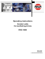
1
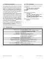
Operating instructions
Control units
for oscillating drives
ESG 1000
BA
Rhein-Nadel Automation GmbH
Table of contents
Chapt........................................................................................................................
1
Page
Technical data
1.1 Functional description.....................................................................................
1.2 EG - conformity..............................................................................................
1.3 Technical data.................................................................................................
3
3
3
2
Safety notes...................................................................................................
4
3
Information for starting ...............................................................................
4
3.1
3.2
3.3
3.4
3.5
3.6
Explanations on the term OPERATING MODE...............................................
Switching over the operating mode..................................................................
Setting the minimum and maximum output voltage..........................................
Switching over to a different mains voltage.....................................................
Releasing the function by external components..............................................
Changing the soft start time............................................................................
4
5
5
5
6
6
4
Plan showing the position of the operating elemements on the boards.....
6
5
Dimensional drawing.....................................................................................
7
6
Connection diagram.......................................................................................
7
7
Stockkeeping of spare parts and after sales service.......................................
8
Rhein - Nadel Automation GmbH
Seite 2
control unit ESG 1000
1.1 Functional description
1.2
The compact design of the control unit can supply
all RNA-control units up to a load current of 6
ampere. It is intended for individual installation directly at the oscillating drive and completely pluggable. The correcting range for the potentiometer
in the front plate has been adjusted in the factory
at a reference drive and allows the adjustment of
the output voltage from 40 to 280 volteff .
The illuminated rocking switch in the front plate
separates the control unit with 2 poles from the
mains. For frequent switching or operation with a
superordinated control unit there is the possibility
of wattless disconnection by means a potentialfree contact as well as by 16-30VDC voltage signal. The intervention into the device necessary for
that is described under point 3.5, Release of the
function by external components.
The soft start, a time-controlled bringing-up of
power to the adjusted value after switching on, is
fixed with approx. 0.5 seconds. If necessary this
time can be changed in the device.
The control device corresponds to the following
regulations:
EC- EMV regulation 89/336/EWG;
EC - Low voltage regulation
(73/23/EEC).
UL / CSA
1.3
EC - Conformity
Applied harmonized standards:
EN 60204, T.1
EC - EMC - regulation EN 50081-1, EN
50011, limiting value category B
EC - EMV - regulation EN 50082, degree
of interference - test level III
Applied national technical specifications:
BGV 2A
Technical data
Mains connection: 230 Volt AC, 50/60 Hz, +10 -15%
or
115 Volt AC, 50/60 Hz, +10 -15% , internally selectable
Output voltage: 40...208 Volt (eff.) adjustable, (230 V mains)
20...105 Volt (eff.) adjustable, (115 V mains)
Load current: max. 6 Amp.(eff)
Safety fuse: Fine-wire fuse 5 x 20; 6,3 MT time-lag
Operating modes: 1. symmetric full wave operation
(oscillating frequency = double mains frequency)
2. asymmetric half wave operation
(oscillating frequency = mains frequency
Operating mode selection: Encoding bridge in the load plug
Function release: selectable by internal jumpers
Release by external contact:: potential-free make contact, load approx. 6 mA
Release by external signal: Reverse battery protected input, level 16...30 VDC
at 24 Volt approx. 8 mA
Soft start: internally adjustable, standard approx.. 0,5 sec.
Insulation type: IP 54
Radio interference suppression: according to EMV - regulations
Dimensions: 104 x 213 x 153 (width x height x depth)
Rhein - Nadel Automation GmbH
Seite 3
control unit ESG 1000
2
Safety notes
3
The safety notes shall in any case be read and
understood. Their observance secures the conservation of valuable material and avoids health
impairment.
Information for starting.
Before the mains connection is made
and the control unit is switched on, the
following points must in any case be
checked:
• Is the control unit closed properly
and with all screws?
• Are the existing plug fixing devices
locked into place/screwed down?
• Are all cables and ducts undamaged?
• Is the INTENDED USE guaranteed?
• Does the mains voltage indication
comply with the local power supply
network?
• Does the mains frequency indication at the oscillating drive comply
with the local power supply network?
• Is the correct operating mode set at
the control unit? (on that read explanation operating mode)
The symbol of the pointing hand
is shown in these operating instructions at points, which must
be particularly observed, so that
recommendations, regulations,
notes and the correct procedure
of work can be observed, as well
as damage and destruction of
the machine and/or other equipment parts is avoided.
Electric danger,
eg. at work under voltage
Only if all above mentioned questions can be answered
with yes, the control unit can be put into operation.
Work at electrical equipment of the machine/equipment may only be carried out
by a qualified electrician or by trained
personnel under direction and supervision of a qualified electrician according to
the electronic regulations!
At initial starts or starts after repair work
or exchange of control units/oscillating
drives the minimum output should be set
at the control unit before switching on
the device. When bringing up the output
it must be taken care for correct function.
All safety and danger notes at the machine / equipment must be observed!!
The electrical equipment of a machine /
equipment must be examined regularly.
Faults, eg. loose connections or damaged cables, must be eliminated immediately!
Before opening the device unplug the
power plug!
Rhein - Nadel Automation GmbH
Seite 4
3.1
Explanations on the term OPERATING MODE
RNA - Oscillating drives are mechanical spring vibrators, which, according to weight and/or size, are adjusted to an oscillating frequency near the mains frequency. Two operating modes are possible:
1. Asymmetrical half-wave operation - the oscillating
drive operates with mains frequency.
2. Symmetrical full-wave operation - the oscillating
drive operates with double mains frequency.
control unit ESG 1000
From that the following details result for the oscillating
frequency:
Mains frequency
Operating
mode 1
Operating
mode 2
50 Hz
60 Hz
Oscillating freOscillating frequency50 Hz = quency 60 Hz =
3000 min-1
3600 min-1
Oscillating freOscillating frequency 100 Hz = quency 120 Hz =
6000 min-1
7200 min-1
At a mains with 50 Hz only oscillating drives with 50 Hz
or 100 Hz oscillating frequency can be operated, at a
mains with 60 Hz, however, only oscillating drives with
60 H7 or 120 Hz oscilllating frequency. The control unit
can operate in both operating modes. It must, however,
be switched into the correct operating mode. The
mains frequency is of no importance for the control unit.
3.3
The control units have been adjusted in the factory at a
reference drive. In special cases or after modifications
a readjustment may become necessary. Here it must in
any case be observed:
The output voltage can only be measured
with an oscillating drive being connected!
The measuring device must be designed
for real effective measurement. (TrueRMS), other measuring devices indicate
random values. The load plug must be
plugged in, as otherwise the measurement
possibly takes place in the wrong measuring mode.
As the adjustment of the output voltage requires feeding of the mains voltage, the following safety note is
very important:
Feed the supply voltage only by means of a
safety transformer ! Carry out the measurements in the rooms/zones permitted for
that. This measurement requires the employment of qualified professionals. After
the measuremtn the control device must be
put back into the original condition, as otherwise the release of series is stopped!
Threaded fitting M20
grey –2, 100 Hz oscillation frequency
black –1, 50 Hz oscillation frequency
metal-EMV-threaded fitting
for frequency regulated devices
Important is the remark that the adjusting devices for
the output voltage are not reactionless towards each
other. I. e. that at a change of the maximum voltage
the minimum voltage is slightly changed as well - and
vice versa. That possibly means a repeated adjustment
of both trimming potentiometers.
3.4
3.2
Switching over to a different mains
voltage
The selection of the operating mode takes place by entering a code into the load plug of the oscillating drive.
A jumper in the plug from connection 3 to 4 switches
the control unit into operating mode 2: 100 or 120 Hz. If
this connection is missing, the control unit operates in
the operating mode 1: 50 or 60 Hz.
As a standard oscillating transport units are provided
with the correct code in the plug. To assist the user, the
threaded cable fitting has distinguishing colours on the
connector jack for better recognition
BLACK for operating mode 1, 50 Hz or 60 Hz,
GREY for operating mode 2, 100 Hz or 120 Hz.
Rhein - Nadel Automation GmbH
Setting the minimum and maximum
output voltage
Seite 5
Switching over to a different mains
voltage
The control unit can be operated at 230 V, 50/60 Hz as
well as at 115 V, 50/60 Hz, must, however, be switched
over to this voltage ,
Changing from 230V to 115V:
Take the plug out of the electrical socket and open the
device on the right side. Toggle the switch and close
the side of the device. Test run. UMAX may have to be
re-adjusted.
(See the layout plan for the adjustable parts, figure 3)
control unit ESG 1000
Release by voltage signal
3.5
Releasing the function by external
components
The standard adjustment of the control unit provides
that the oscillating drive starts, when the mains
switch is switched on. Should it be preferred that the
control unit work in start-stop operation, then the
control unit should be opened — observing all of the
precautionary measures listed above — and the
jumper S1 re-plugged; see layout plan, figure 3.
Remove the dummy plugs on the side of the casing
and install a threaded cable fitting M16 with strainrelief; the cable will be fed through here for release.
Release is achieved in two possible ways:
Release by a contact
This simple, cost-efficient solution works in a way that
the control unit is released by making the contact and
the oscillating drive operates. The connection is made
at the terminals 33 - 34. Some points should be observed:
• The connection is fed with mains voltage! Cable
type and colour, insulation regulations must be observed, the contact must of course be potential-free.
• Starting at 2 m and above, the cable must be
shielded; the shielding is situated on one side of the
control unit on the protective earth conductor.
• The cable length should not exceed 5 meter.
• The cable may not be installed in immediate
neighbourhood to high-energy switching equipments or strong interference fields.
4.
The connection is done on the fasteners 31 (GND) and
32 (+24 VDC). The drive starts, when a signal is fed
between 10 and 30 volt direct current in correct polarity. The input is protected against faulty polarity. The
use of an optocoupler in the control unit makes the input potential-free and allows the installation with unscreened cables of nearly any length. Here too highenergy interferences should be avoided.
3.6
Canging the soft start time
The soft start, the time-controlled bringing up of the
output to the adjusted value is an effective protection
for the oscillating drive against magnet impacts. At
small oscillating drives, which start with high cycle
times, the standard time is not necessary in any case,
it does even impede the production flow. At the trimmer
SOFT START the run-up time can be adjusted. As the
case must be opened for this change as well, the
safety notes mentioned above should be oberserved.
Plan showing the position of the
operating elements on the boards
Potentiometer
Pos. 59
ESG 1000
Token
10kOhm
S0
Release
X1
33 34
External contact
Freigabe
31 32
S1
Externer Kontakt
External voltage
24 V. DC
S1
Commentasy
Switch
110 V – 230 V
Electric voltage
External release
Externe Spannung
24 V, DC
1
Electric cable Pos. 80
2
LP 1334
Electric switch Pos. 52
Netzkab el Pos. 80
6
5
4
3
NetzschalterPos. 52
9
X8 X18
8
7
X16
Casing ground
B
When replacing the fuse the
preset value of M 6,3 A is to be
used in any case. A fuse which
is rated too high can lead to
breakage of the conrol unit.
Detail
Erdung
Gehäuse
Detail B
Exit xocket
Pos. 50 + 51
3
4 1
2
PE
Ausgangsstec kdose
Pos. 50 + 51
Rhein - Nadel Automation GmbH
Seite 6
control unit ESG 1000
5.
Scale Drawing
6.
Connecting Diagram
The jumper must be diverted to enable the external release.
Jumper
Internal release
Attention! The connectors for the release contacts
are under voltage!
The bowl feeder operates when the release signal is
passed or when the release contact is closed.
Power
Release
GND
potentially
free
contact
Operation selection:
Connectors XS 1/3 -> 4 connected, oscillation frequency = double the current frequency
Connectors XS 1/3 -> 4 open, oscillation frequency =
current frequency
Electric socket
230V/50/60Hz
Load
max. 6A
Rhein-Nadel Automation GmbH
Reichsweg 19/42
Tel (+49) 0241/5109-159
Internet: www.rna.de
D - 52068 Aachen
Fax +(49) 0241/5109-219
E-mail: [email protected]
Rhein-Nadel Automation GmbH
Zweigbetrieb Lüdenscheid
Nottebohmstraße 57
D - 58511 Lüdenscheid
Tel (+49) 02351/41744
Fax (+49) 02351/45582
Rhein-Nadel Automation GmbH
Zweigbetrieb Ergolding
Ahornstraße 122
D - 84030 Ergolding
Tel (+49) 0871/72812
Fax (+49) 0871/77131
HSH Handling Systems AG
Wangenstr. 96 CH - 3360 Herzogenbuchsee
Tel +(41) 062/95610-00
Fax (+41) 062/95610-10
Internet: www.rna.de E-mail: [email protected]
RNA AUTOMATION LTD
Hayward Industrial Park
Tameside Drive, Castle Bromwich
GB - Birmingham, B 35 7 AG
Tel (+44) 0121/749-2566
Fax (+44) 0121/749-6217
Internet: www.rna-uk.com E-mail: [email protected]
Vibrant S.A.
Pol. Ind. Famades C/Energia Parc 27
E - 08940 Cornella Llobregat (Barcelona)
Tel (+34) 093/377-7300 Fax (+34) 093/377-6752
Internet : www.vibrant-rna.com E-mail: [email protected]
RNA Automated Systems Inc.
1349 Sandhill Drive Unit 101
Ancaster, Ontario
Canada, L9G 4V5
Tel (+1) 905/3049950
Fax (+1) 905/3049951
Mobil (+1) 5197546955
Email [email protected]
www.rna-can.com
VT-BA-ESG1000-GB-00
Rhein - Nadel Automation GmbH
Stand: 26.10.05
Seite 8
control unit ESG 1000