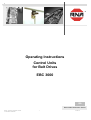
1
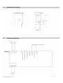
®
Operating Instructions
Control Units
for Belt Drives
EBC 3000
BA
Rhein-Nadel Automation GmbH
Rhein - Nadel Automation GmbH
VT-BA EBC 3000GB
1
20.05.10
Table of Contents
Chapter ..........................................................................................................................
Page
1
Technical Data
3
2
Safety Instructions ..........................................................................................
3
3
Starting Instructions .......................................................................................
4
4
Dimensioned Drawing .....................................................................................
6
5
Connection Diagram ........................................................................................
6
Declaration of Conformity
in terms of the Low Voltage Directive 2006/95/EC
and the EMC Directive 2004/108/EC
We herewith declare that the product is in conformity with the following provisions:
Low Voltage Guideline 2006/95/EC
EMC Directive 2004/108/EC
Applied harmonised standards:
DIN EN 60204 T1
EN 60439-1
Comments:
Rhein-Nadel-Automation
--------------------------------Managing Director
Jack Grevenstein
Rhein - Nadel Automation GmbH
VT-BA EBC 3000GB
2
20.05.10
1 Technical Data
1.1 Functional description
The control unit EBC 3000 was developed to operate the RNA mini-band conveyor FP 15. The applied pulse width
modulation generates high efficiency and good start-up characteristics through a near 1 form factor. All operating
controls including the plug-in device for the motor connection are arranged on the front panel.
A switched-mode power supply in accordance with VDE 0551 generates the operating voltage of max. 24 volts for the
belt drive, so the motor voltage is a contact-safe protective extra-low voltage.
An internal current scanning (I x R compensation) equalizes speed fluctuations when the load on the conveyor belt
changes.
* Minimum and maximum output voltage, Umin und Umax, as well as maximum motor current, Imax, are continuously
adjustable on the board.
* The conveyor belt can be powerlessly started and stopped over additional wiring.
* In addition, one can regulate the target value over an external 0-10V or 0-20mA signal.
* Over a voltage-free contact, one can reverse the sense of rotation of the connected motor.
* The control unit is designed for a mains voltage from 110 volts AC to 230VAC. The control unit checks the mains
voltage and adjusts itself automatically.
1.2
EC Conformity
The control unit complies with the following regulations:
EMC Directive 2004/108/EC
Low Voltage Guideline 20065/95/EC
Applied harmonised standards:
EN 60204, T.1
EN 60439-1
1.3
Technical data
230V; ± 10%; 50 / 60 Hz
or 115V; ± 10%; 50/60 Hz
5 x 20; 2A medium time-lag
0...28 V DC
0.4...2 A
0-10V 0-20mA
Power supply
Primary fuse
Output voltage
Output current
External adjustment
External release
Case dimensions
Interference suppression and resistance to jamming
Type of protection
Ambient temperature
2
over a voltage-free contact
or 24 V voltage signal
210 x 90 x 150 (H x W x D)
conformity in accordance with EMC Directive
IP 54
0...50C°
Safety Instructions
The safety instructions must always be read and understood. Observance of these instructions ensures that valuable
material is maintained and damage to health avoided.
One must make sure that every person working with this control unit is acquainted with the safety instructions and also
follows them.
The unit described here is a controller for the operation of RNA belt drives. The limiting values in Technical Data are to
be observed.
Rhein - Nadel Automation GmbH
VT-BA EBC 3000GB
3
20.05.10
Note!
This hand indicates that there are tips on how to use the control unit.
Attention!
This warning triangle indicates safety instructions. Non-observance of this warning can result in
serious injuries or death!
Work on electrical equipment of the machine/installation may only be carried out by a qualified electrician
or by an instructed person under the directions and supervision of a qualified electrician according to the
electrotechnical regulations!
Please observe all notes on safety and danger on the machine/installation!
The electrical equipment of a machine/installation is to be inspected and checked regularly. Defects like
loose connections or damaged cables must be eliminated immediately!
Before putting the machine into operation, one must make sure that the protective conductor (PE) is
installed at the connecting point and that it is intact. Only approved testing equipment may be used to
check the protective conductor.
3
Starting Instructions
Before connecting to the mains and switching on the control unit, the following points must be checked:
• Is the control unit properly closed with all its screws?
• Are the existing plug-in fixing devices locked into place / screwed tight?
• Are all cables and bushings intact?
• Is the INTENDED USE guaranteed?
• Does the indicated supply voltage on the control unit conform with the local power supply network?
The control unit may only be put into operation if all above questions can clearly be answered with Yes.
3.1
Basic factory setting
The control units are set at the works as follows:
• Minimum output voltage:
4.9 volts;
• Maximum output voltage:
25.5 volts;
• Maximum load current:
1.5 amp.
In special cases or after modifications, a readjustment may become necessary, for which the following must be
observed:
The maximum output voltage and the maximum load current for the conveyor belt FP 15 may not be adjusted higher nor
may the minimum output voltage be adjusted lower than indicated above.
It is also important to note that the potentiometers for the output voltage are not reactionless towards each other. This
means that a change in the maximum voltage also slightly changes the minimum voltage – and vice versa. Therefore, it
is possible that both potentiometers may have to be adjusted several times.
3.2
External adjustment with 0-10V or 0-20mA
Before connecting, the right-hand side panel of the unit has to be opened.
Rhein - Nadel Automation GmbH
VT-BA EBC 3000GB
4
20.05.10
Before opening the control unit
pull the mains plug!
Then wait 10 min. until the power pack is discharged.
Connection is done on the XK1 terminal strip.
In control mode with 0-10 volts
onto terminal XK1.3 +10 volts
Terminal XK1.5 GND
In control mode with 0-20mA
onto terminal XK1.4 +20mA
Terminal XK1.5 GND
3.2.1
Reversing mode
Before connecting, the right-hand side panel of the unit has to be opened.
Before opening the control unit
pull the mains plug!
Then wait 10 min. until the power pack is discharged.
To activate the reversing mode, connect a voltage-free contact onto terminals XK1.9 and XK1.8. When switching the
sense of rotation, the motor stops a moment and then starts in the opposite moving direction at the set speed. If the
sense of rotation is reversed without switching or if the contact is open, the motor will run in the set sense of rotation.
3.3
Release of the function through external components
The standard adjustment of the control unit makes sure that the oscillating belt drive starts when the mains switch is
switched on. If the control unit is to operate without disconnection from the mains in the Start-Stop mode, the control unit
is to be opened by observing the above-mentioned safety notes. The blind plug at the side of the case replaces a screw
fitting with strain relief size M16. This is where the cable for the release is lead through. There are two possible ways of
performing a release:
Release through a contact
The way this simple and economical solution works is that a contact releases the control unit by closing and the belt
drive runs. The connection is made on terminals 7 and 9; the jumper put in at the works is to be removed. At the same
time, please remember the following:
• There is voltage in the connection! Cable type and colour as well as insulation regulations must be observed; the
contact must, of course, be voltage-free.
• The cable may not be installed in the immediate vicinity of high-energy switching equipment or strong interference
fields.
Release through a voltage signal
The signal is connected to terminals 6 - and 7 +; the jumper, i.e. terminals 7 and 8, have to be removed. The drive starts
when there is a signal between 10 and 30 volts DC in correct polarity. The input is protected against wrong polarity. The
use of an optocoupler in the control unit makes the input voltage-free and allows one to install unshielded cables of
almost any length. However, high-energy interferences must be avoided here too.
Rhein - Nadel Automation GmbH
VT-BA EBC 3000GB
5
20.05.10
4
Dimensioned Drawing
5
Connection Diagram
Rhein - Nadel Automation GmbH
VT-BA EBC 3000GB
6
20.05.10
Rhein-Nadel Automation GmbH
Reichsweg 19/23 Ÿ D - 52068 Aachen
Tel (+49) 0241/5109-159 Ÿ Fax +(49) 0241/5109-219
Internet www.rna.de Ÿ Email [email protected]
Rhein-Nadel Automation GmbH
Zweigbetrieb Lüdenscheid
Nottebohmstrasse 57 Ÿ D - 58511 Lüdenscheid
Tel (+49) 02351/41744 Ÿ Fax (+49) 02351/45582
Email [email protected]
Rhein-Nadel Automation GmbH
Zweigbetrieb Ergolding
Ahornstrasse 122 Ÿ D - 84030 Ergolding
Tel (+49) 0871/72812 Ÿ Fax (+49) 0871/77131
Email [email protected]
HSH Handling Systems AG
Wangenstr. 96 Ÿ CH - 3360 Herzogenbuchsee
Tel +(41) 062/95610-00 Ÿ Fax (+41) 062/95610-10
Internet www.rna.de Ÿ Email [email protected]
RNA AUTOMATION LTD
Hayward Industrial Park
Tameside Drive, Castle Bromwich
GB - Birmingham, B 35 7 AG
Tel (+44) 0121/749-2566 Ÿ Fax (+44) 0121/749-6217
Internet www.rna-uk.com Ÿ Email [email protected]
Vibrant S.A.
Pol. Ind. Famades C/Energia Parc 27
E - 08940 Cornellà Llobregat (Barcelona)
Tel (+34) 093/377-7300 Ÿ Fax (+34) 093/377-6752
Internet www.vibrant-rna.com Ÿ Email [email protected]
Rhein - Nadel Automation GmbH
VT-BA EBC 3000GB
7
20.05.10