1
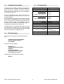
Operating Instructions
Control Units
for Belt Drives
EBF-05
BA
Rhein - Nadel Automation GmbH
1
Control Units for Belt Drives
Rhein-Nadel Automation GmbH
Contents
1
Technical Data
1.1
1.2
1.3
Functional description .......................................................................................
EC Conformity ..................................................................................................
Technical data ..................................................................................................
3
3
3
2
Safety instructions ..........................................................................................
4
3
Instructions for the initial start-up ..................................................................
4
3.1
3.2
3.3
3.4
3.5
Factory setting .....................................................................................................
Standard programming .......................................................................................
Functions of the display and buttons ..................................................................
External release ..................................................................................................
Alarm ..................................................................................................................
4
5
5
6
6
4
Mechanical construction .................................................................................
6
5
Dimensioned drawing ......................................................................................
7
6
Connection diagram .........................................................................................
7
Rhein - Nadel Automation GmbH
2
Control Units for Belt Drives
1.1
Functional description
1.3
Control units of the EBF 05 series are microprocessor-controlled units to adjust the speed settings on
RNA belt drives, elevators and plate conveyors.
There are two types available for power adaptation:
0.370 kW and 0.75 kW.
Mains voltage
Output voltage
Output frequency
Power class 370
Motor rating
Rated current of the unit
From the monophase mains – 230 V, 50 or 60 Hz –
the units generate a three-phase mains with an adjustable frequency.
Asynchronous squirrel-cage motors driven with this
are continuously adjustable and the range reaches
from 17 Hz to 85 Hz. The lower limits result from the
minimum speed needed for self-ventilation, the upper limits set the maximum permissible speed according to the manufacturer’s instructions.
Power class 750
Motor rating
Rated current of the unit
Set-point value
Release
Status relay
Permissible ambient temp.
Measurements 370 and
750
Radioshielding and
resistance to jamming
A release input for a powerless start and stop of the
drive as well as a signal output to recognise a fault
have been led to the terminal strip and are available
to the user by means of additional wiring.
1.2
Technical Data
Type of protection
Type of protection
EC Conformity
230 V +10% 50/60Hz
3 x 0-210 Volt AC
0.5 – 120 Hz
370 W
2.1 A
750 W
3.6 A
Potentiometer 10kΩ
Contact
250 V, 2A
0 – 50 °C
150 x 205 x 180 mm
according to EMC
Guideline
conformity
IP54
IP54
The control unit complies with the following directives:
EC EMC Guideline 89/336/EWG;
EC Low Voltage Guideline
(73/23/EWG).
Harmonised norms applied:
EN 60204, T.1
EC EMC Guideline EN 50081-1,
EN 50011,
Limit-value class B
EC EMC Guideline EN 50082,
Fault degree test level III
National technical specifications applied:
BGV 2A
Rhein - Nadel Automation GmbH
3
Control Units for Belt Drives
2
Safety instructions
and limb!
The safety instructions should by all means be read
and understood. The observance of these instructions ensures that valuable material is maintained
and damage to health is avoided.
One must make sure that every person working with
this control unit is acquainted with the safety instructions and also follows them.
The unit described here is a control unit for the operation of RNA belt drives. The limiting values in the
technical data are to be observed.
Before putting the machine into operation, please make sure that the protective
conductor (PE) is installed at the
connecting point and that it is intact. To
check the protective conductor, only approved testing equipment may be used.
3
Note!
This hand indicates tips on how to
use the control unit.
Instructions for the initial start-up
The connecting cable between the
control unit and the conveyor belt
has to be screened, and the screen
connected on both sides to the protective conductor.
The maximum cable length is 2
metres.
Attention!
This warning triangle indicates
safety instructions. Non-observance
of this warning can result in serious
injuries or death!
Before connecting to the mains and
switching on the control unit, the following points must be checked:
•
•
Work on electrical equipment of the machine may only be carried out by a qualified electrician or by an instructed person
under the directions and supervision of a
qualified electrician according to the electrotechnical regulations!
After having connected the control unit to the power
supply and switched on the mains switch, the conveyor belt begins to move. A restart muting after a
power failure is not provided for with these control
units.
Please observe all notes on safety and
danger on the machine!
The electrical equipment of a machine is
to be inspected and checked regularly.
Defects like loose connections or damaged cables have to be eliminated immediately!
3.1
Factory setting
The control unit is programmed to the set-point value
by a potentiometer.
If a control unit is delivered together with a conveyor
belt, the operational parameters will already have
been programmed for this conveyor belt. The settings are recorded on the parameter sheet.
If the data of the driving motor is unknown, the following settings will be made:
• Minimum frequency
17 Hz;
• Maximum frequency
85 Hz;
• Current limit
0 A;
Before opening the unit,
pull the mains plug
and wait at least 5 minutes!
The dangerous energy in the
intermediate circuit degrades only
slowly after disconnection from the
mains!
Non-observance means danger to life
Rhein - Nadel Automation GmbH
Is the INTENDED USE
sure?
Does the indicated supply
voltage on the control unit
correspond with the local
network?
Start/Stop ramp
4
1 sec. each
Control Units for Belt Drives
3.2 Standard programming of the frequency converter EBF 05
Meaning
Display
bfr
ACC
dec
LSP
HSP
ltH
tCC
tct
Atr
3.3
Setting value
Motor frequency according to rating 50 Hz
plate
Run-up time
1 sec
Run-down time
1 sec
Small frequency
17 Hz
Large frequency
85 Hz
Thermal motor current
0A
Type of control
ACT - 2C
(2-wire control)
Logic 0 or 1 is taken into account for LEL
switching on or off
Automatic restart
nO
Functions of the display and buttons
Rhein - Nadel Automation GmbH
5
Control Units for Belt Drives
3.4
-
3.5
External release
4
Contact release
Remove bridge of binder 10 – 11,
loop in a voltage-free contact.
The connecting cable to the contact has to be
screened.
The screen has to be connected in the control
unit to the protective conductor.
The maximum cable length is 5 m; laying them
together with cables that have perturbing radiation must be avoided.
The construction of the control unit is divided into two
parts: underpart of the housing with fixing plate and upper part of the housing with front panel.
Alarm
The alarm relay is closed when the frequency converter
is under voltage and does not show any faults.
When there is a fault (or a converter without voltage),
the contact drops.
Unlocking the converter after a fault is done as follows:
by switching it off and waiting until the alarm on the
display extinguishes, then by switching the converter on again;
Mechanical construction
The underpart laterally bears the mains switch and the
cable bushing. The mains filter and the terminal/contact
strip XS1 have been placed inside.
The frequency converter has been placed in the upper
part together with the thermal coupler; the front panel
with the potentiometer closes the upper part.
For the purpose of changing the frequency converter or
installing additional wiring, 4 slotted screws in the circular taperings of the upper part are to be loosened after
having removed the front panel and then to detach the
upper from the underpart. The terminal/contact strip is
now accessible and can also be detached. The underpart remains on the body of the machine; the installation is now easily accessible.
When mounting, one must make absolutely sure that
the seals are properly in place, otherwise the type of
protection is no longer given.
automatically in the cases described under “Automatic Restart“ (menu FUn, Atr = YES);
by a logic input that is assigned to the function “Reset“ (menu Fun, rSF = LIz).
Rhein - Nadel Automation GmbH
6
Control Units for Belt Drives
6
5. Dimensioned drawing
206
6,3
6
6,3
130
6
22
150
Connection diagram
Alarm relay point
External release
- Contact release
remove bridge of binder 10 and 11
loop in a voltage-free contact
- Voltage release
remove bridge of binder 10 and 11
connect max. 24V+ to binder 11
connect 0V to binder 12 (do not
use binder 10-internal + 15V)
Altivar 11
Red Black
Blue
-M1
The control binders that are not connected provide for a number of additional functions and monitorings, which are to
be selected through parameterization. A detailed description can be found in the operating instructions of the frequency converter.
Rhein - Nadel Automation GmbH
7
Control Units for Belt Drives
Rhein-Nadel Automation GmbH
Reichsweg 19/42 y D - 52068 Aachen
Tel (+49) 0241/5109-159 y Fax +(49) 0241/5109-219
Internet www.rna.de y Email [email protected]
Rhein-Nadel Automation GmbH
Zweigbetrieb Lüdenscheid
Nottebohmstraße 57 y D - 58511 Lüdenscheid
Tel (+49) 02351/41744 y Fax (+49) 02351/45582
Email [email protected]
Rhein-Nadel Automation GmbH
Zweigbetrieb Ergolding
Ahornstraße 122 y D - 84030 Ergolding
Tel (+49) 0871/72812 y Fax (+49) 0871/77131
Email [email protected]
HSH Handling Systems AG
Wangenstr. 96 y CH - 3360 Herzogenbuchsee
Tel +(41) 062/95610-00 y Fax (+41) 062/95610-10
Internet www.rna.de y Email [email protected]
RNA AUTOMATION LTD
Hayward Industrial Park
Tameside Drive, Castle Bromwich
GB - Birmingham, B 35 7 AG
Tel (+44) 0121/749-2566 y Fax (+44) 0121/749-6217
Internet www.rna-uk.com y Email [email protected]
Vibrant S.A.
Pol. Ind. Famades C/Energía Parc 27
E - 08940 Cornellà Llobregat (Barcelona)
Tel (+34) 093/377-7300 y Fax (+34) 093/377-6752
Internet www.vibrant-rna.com y Email [email protected]
RNA Automated Systems Inc.
1349 Sandhill Drive Unit 101
Ancaster, Ontario
Canada, L9G 4V5
Tel (+1) 905/3049950 y Fax (+1) 905/3049951
Mobil (+1) 5197546955
Email [email protected]
www.rna-can.com
Rhein - Nadel Automation GmbH
8
Control Units for Belt Drives
VT-BA-EBF05-GB
Rhein - Nadel Automation GmbH
State: 30.10.2006
9
Control Units for Belt Drives