1
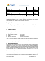
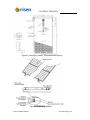
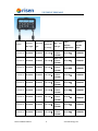
 INSTALLATION MANUAL For Monocrystalline Modules “According with IEC61215 edition 2 & IEC61730 standards” RISEN ENERGY CO., LTD. Address: Meilin Tashan Ind.Zone, Ninghai, Ningbo, Zhejiang, China Website: www.risenenergy.com Email: [email protected] Tel: 86‐574‐59953071 Risen Installation Manual
1
www.risenenergy.com
Overview
Thank you very much for using Risen Energy PV modules. In order to enable the PV modules to be
installed correctly and to generate electric power properly, please read the following operation
instructions carefully before installing and using the modules.
Please remember that you are operating a product that generates electricity, and therefore certain safety
measures need to be implemented in order to avoid accidents.
1. Instruction
Risen Energy Company Limited (Risen Energy) has a long history of successful innovation within the
solar industry. The company was fund in 1986 and began researching photovoltaic modules in 1999. The
company has several fully integrated product lines, including wafers, cells, Mono and Polycrystalline
Silicon modules (MODULES). Risen Energy products are exported to overseas markets. With an
experienced international management team and a strong reputation for innovation, Risen Energy
supplies the highest quality MODULES in a range of sizes designed to meet the requirements of the most
demanding energy and power users worldwide.
2. Power MODULES
Risen Energy MODULES consist of a series of electrically interconnected crystalline silicon solar cells,
which are permanently encapsulated between a tempered glass cover, an EVA potted with TPT back
sheet. The entire laminate is secured within an anodized aluminum frame for structural strength; ease of
installation, and to protect the cells from the most severe environmental conditions. The MODULES
which are listed below table applicable for this Manual, the data are tested at STC. The MODULES power
tolerance is +/-3%
Application
Max
Isc
Voc
(A)
(V)
36.2
5.5
45.0
74.7
A
1000V
5.19
36.6
5.57
45.1
75.6
A
1000V
195
5.3
36.8
5.6
45.3
76.8
A
1000V
SYP200S-M
200
5.4
37.0
5.72
45.4
77.0
A
1000V
SYP220S-M
220
4.58
48.0
4.82
59.5
76.6
A
1000V
SYP230S-M
230
4.77
48.2
5.06
59.8
76.0
A
1000V
SYP240S-M
240
4.95
48.4
5.26
60
76.0
A
1000V
SYP250S-M
250
5.15
48.6
5.45
60.3
76.2
A
1000V
SYP260S-M
260
5.33
48.8
5.66
60.5
76.0
A
1000V
Pmpp
Impp
(W)
(A)
SYP185S-M
185
5.11
SYP190S-M
190
SYP195S-M
Modules
Vmpp(V)
FF%
class
voltage
maximum over current
Recommended
parallel
protection ratings
maximum series
configuration
class
SYP185S-M
10A
22
2
Class C
SYP190S-M
10A
22
2
Class C
Modules
Risen Installation Manual
2
module
system
Fire resistance
www.risenenergy.com
SYP195S-M
10A
22
2
Class C
SYP200S-M
10A
22
2
Class C
SYP220S-M
10A
16
2
Class C
SYP230S-M
10A
16
2
Class C
SYP240S-M
10A
16
2
Class C
SYP250S-M
10A
16
2
Class C
SYP260S-M
10A
16
2
Class C
Table 1: Parameters of the Risen Energy MODULES
Under normal conditions, a photovoltaic module is likely to experience conditions that produce more
current and/or voltage than reported at STC. Accordingly, the values of Isc and Voc marked on this
module should be multiplied by a factor of 1.25 when determining component voltage ratings, conductor
current ratings, fuse sizes, and size of controls connected to the PV output.
3. Applications
Risen Energy MODULES are a highly reliable, virtually maintenance free power supply, designed to
operate efficiently in sunlight, these solar modules are ideal for charging storage batteries used to power
remote homes, recreational vehicles, boats, telecommunications systems and other electric generation
application.
4. Climate Condition
Install the RISEN ENERGY Crystalline series MODULES in the following conditions:
●
Ambient temperature:
-40℃ to +40℃
●
Operating temperature:
-40℃ to +85℃
●
Operating Storage temperature:
-20℃ to +40℃
●
Humidity:
below 85RH%
●
Mechanical Load Pressure:
below 112.78lb/ft2 (5400Pa)*.
*Note: the mechanical load bearing (including wind and snow loads) of the MODULES is based on the
mounting methods. The professional system installer must be responsible for mechanical load
calculation according to the system design.
5. Mounting Site Selection
The MODULES should be mounted in a location where they will receive maximum sunlight through the
year and also to be mounted over a fire resistant roof covering rated for the application. In the Northern
Hemisphere, the MODULES should face south, and in the Southern Hemisphere, the MODULES should
face north. MODULES facing 30degrees away from true South (or north) will lose approximately 10 to 15
percent of their power output. If the MODULES face 60 degrees away from true South (or North), the
power loss will be 20 to 30 percent.
When choosing a site, avoid trees, buildings or obstructions which could cast shadows on the solar
modules especially during the winter months when the arc of the sun is lowest over the horizon. Shading
causes loss of output, even though the factory fitted bypass diodes of the MODULES will minimize any
Risen Installation Manual
3
www.risenenergy.com
such loss.
Do not install the MODULES close to naked flame or flammable materials.
Do not install the MODULES in a location where it would be immersed in water or continually exposed to
water from a sprinkler or fountain etc.
Do not install the MODULES in a marine environment and/or area where salty wind hit directly.
Do not install the MODULES in corrosive environment, such as corrosive salt area or sulfurous area, etc.
Do not install the MODULE to substitute, even partially a roof or wall of a habitable structure.
6. MODULE Tilt Angle
RISEN ENERGY MODULES connected in series should be installed at same orientation and angle.
Different orientation or angle may cause loss of output power due to difference of amount of sunlight
exposed to the MODULES.
RISEN ENERGY MODULES produce the most power when they are pointed directly at the sun. For
installations where the MODULES are attached to a permanent structure, the MODULES should be tilted
for optimum winter performance. As a rule, if the system power production is adequate in winter, it will be
satisfactory during the rest of the year. The MODULESE tilt angle is measured between the solar
MODULES and the ground (Figure 1). Optimal tilting of MODULES is almost the same as the latitude of
installation location.
Figure 1 MODULES Tilt Angle
7. Mounting the MODULE
The frame of each MODULE has eight 9mm diameter mounting holes (Figure 2 and Figure 3). These are
used to secure the MODULES to the support structure. For installation safety, we recommend that
minimum torque of screw between 5-8Newton-meters. The mounting method is as Figure 4 below.
The four holes close to the corners of the MODULE are most often used for mounting. Clearance
between the MODULES frame and the mounting surface may be required to prevent the junction box
from touching the surface, and to circulate cooling air around the back of the MODULE. In case the
MODULES will be mounted on the roof or wall of a building, the standoff method or the rack method are
recommended.
Standoff: The MODULES are supported parallel to the surface of the building wall or roof. Clearance
between the MOUDLES frames and surface of the wall or roof is required to prevent wiring damage and
Risen Installation Manual
4
www.risenenergy.com
to allow air to circulate behind the MODULE. The recommended standoff height is Class Ratings.
Rack: The supporting frame is used to mount modules at correct tilt angle. The MODULES are not
designed for integral mounting as part of a roof or wall. The mounting design may have an impact on the
fire resistance.
Figure 2: Aluminum frame: 1580X1070X50X35(mm)
Risen Installation Manual
5
www.risenenergy.com
Figure 3: Aluminum frame: 1580X808X50X35(mm)
Figure 4: Mounting Method
Risen Installation Manual
6
www.risenenergy.com
8. Wiring
For MODULES wiring, when your PV system
system open circuit voltage. Check your local
includes other components (batteries, charge
codes for requirements.
controllers, inverters, etc.), be sure to follow the
safety recommendations of their manufacturers.
These
MODULES
contain
factory
installed
bypass diodes. If these MODUES are incorrectly
connected to each other, the by-pass diodes or
cable or junction box may be damaged.
For array wiring, the terms “array” is used to
describe the assembly of several MODULES on a
support structure with associated wiring. Use
copper wire that is sunlight resistant and is
insulated to withstand the maximum possible
9. Grounding
For grounding, there is a grounding label and two holes at the panel, of whose position refer to the Figure
1. Size and earth the equipment grounding conductor in accordance with local requirements or the IEC.
Attach the equipment grounding conductor to the module frame using the hole and hardware provided.
Note that a stainless steel washer is used between the ground wire and the module frame (see Figure 5).
The diameter of hole on module is 4mm. The diameter of nut is 5mm. According to GB/T 97.1, d1 is
5.3mm, d2 is 10mm, h is 1mm. These washers are used to avoid corrosion due to dissimilar metals.
Tighten the screw that the minimum of torque screw between 0.5 and 1.0 Newton meters. We
recommend you attach all module frames to an earth ground. Attach a separate ground wire to one of the
extra mounting holes on the module frame with a self-tapping screw. The racks must also be grounded
unless they are mechanically connected by nuts and bolts to the grounded modules. Grounding is
achieved by securing the array frame for both roof and field mounted applications. Please note all
washers and nuts are stainless steel.
Figure 5: Grounding method
Risen Installation Manual
7
www.risenenergy.com
10. Junction Box
Modules
Junction
Connector
Box Type
type
Connector
temperatu
re ratings
Wire
size
and type
Cable
ambient
temperature
Bypass
diodes
type
40 to 90℃
10SQ050
40 to 90℃
10SQ050
40 to 90℃
10SQ050
40 to 90℃
10SQ050
40 to 90℃
10SQ050
40 to 90℃
10SQ050
40 to 90℃
10SQ050
40 to 90℃
10SQ050
40 to 90℃
10SQ050
2PfG 1169
SYP185S-M
PV-ZH008
PV-ZH202
-40 to 85℃
1*4.0mm
2*900MM
2PfG 1169
SYP190S-M
PV-ZH008
PV-ZH202
-40 to 85℃
1*4.0mm
2*900MM
2PfG 1169
SYP195S-M
PV-ZH008
PV-ZH202
-40 to 85℃
1*4.0mm
2*900MM
2PfG 1169
SYP200S-M
PV-ZH008
PV-ZH202
-40 to 85℃
1*4.0mm
2*900MM
2PfG 1169
SYP220S-M
PV-ZH008
PV-ZH202
-40 to 85℃
1*4.0mm
2*900MM
2PfG 1169
SYP230S-M
PV-ZH008
PV-ZH202
-40 to 85℃
1*4.0mm
2*900MM
2PfG 1169
SYP240S-M
PV-ZH008
PV-ZH202
-40 to 85℃
1*4.0mm
2*900MM
2PfG 1169
SYP250S-M
PV-ZH008
PV-ZH202
-40 to 85℃
1*4.0mm
2*900MM
2PfG 1169
SYP260S-M
PV-ZH008
PV-ZH202
-40 to 85℃
1*4.0mm
2*900MM
Partial shading of an individual MODULE can cause a reverse voltage across the shaded MODULE.
Risen Installation Manual
8
www.risenenergy.com
Current is then forced to go through the shaded area by the other MODULE. By having a bypass diode,
the forced current will bypass the shaded module in a series circuit, thereby minimizing module heating
and array current losses. For 12-volt systems and higher: Each solar module junction box has a diagram
illustrating the proper direction for the by- pass diode to be installed between two of the terminal screws.
When the solar MODULES are connected as individual series strings first, and then these strings are
connected in parallel, bypass diodes should be used in each junction box, this is the simplest wiring
arrangement for most installations. At a minimum the bypass diodes must have the following electrical
characteristics:
• Rated Average Forward Current above maximum system current at the highest MODULES operating
temperature.
• Rated Repetitive Peak Reverse Voltage above maximum system voltage at the lowest MODULE
operating temperature.
11. Preparation before Installation
Unpacking
Once the PV MODULES have been shipped to the installation site all of the parts should be unpacked
properly with care.
Caution: The environment for unpacking the MODULES and all other apparatus should be proofed
against dampness and rainfall.
a)
Visual check before installation, to make sure there is no bug in the packing and junction
b)
Check the serial number.
c)
Check the PV MODULES with irradiance of more than 600W/㎡ and get the voltage. In case the
voltage is ZERO, it should not be installed and please contact the supplier.
d)
All the washers, nut, and bolt must be stainless steel.
12. Safety Precautions
a)
Make sure the MODULES are arranged so that the current and voltage characteristics of the array
are within the tolerance of the device to which the array will connect. MODULES sold in Europe rate
up to 1000V DC.
b)
For rooftop installations, this MODULE has Class C Fire Rating and must be installed over a roof of
appropriate fire resistance. Consult your local building department to determine approved roofing
materials.
c)
The shock hazard increases as modules are connected in parallel producing higher current. The
shock hazard increases as modules are connected in series producing higher voltages. To avoid the
hazard of electric shock, work only under dry conditions, with dry module and tools.
13. Warnings
MODULES are live electrical power source when exposed to light. Array of many MODULES can cause
lethal shock and burn hazards. Although single module produces only a low voltage and current, shocks
and burns are still a potential hazard. MODULES should be covered with an opaque material during
installation to avoid shocks or burns. Do not touch the live parts of cables and connectors. Using
appropriate safety equipment (insulated tools, insulating gloves, etc) when handling MODULES.
Risen Installation Manual
9
www.risenenergy.com
14. Permit
Before installing your system, contact local authorities to determine the necessary permitting, installation
and inspection requirements.
15. Installation and Operation
•
Systems should be installed by qualified professionals only. The process involves electricity and can
be dangerous if the installing personnel are not familiar with the appropriate safety procedures.
•
Do not step on the module.
•
Artificially Sunlight shall not be concentrated on the module.
•
Although the modules are quite rugged, the glass can be broken (and the module will no longer work
properly) if it is dropped or hit by tools or other objects.
•
Solar modules have a protective front glass. Broken solar module glass is an electrical safety hazard
(electric shock and fire). These modules cannot be repaired and should be replaced immediately.
d)
Do not damage the back sheet of a MODULE, to avoid the hazard of electric shocks and fire.
Children and unauthorized persons should not be allowed close to the installation of the PV
MODULES.
e)
Do not remove any part installed by Risen Energy or disassemble the MODULES.
f)
Protect plug against soiling, do not make any plug connections using soiled plug contacts.
g)
MODULES must be carried more than two persons by the frame and wear non-slip gloves.
h)
Do not use MODULES of different configurations in the same systems.
i)
Do not drill additional mounting holes in the MODULES frames, as it will void the warranty.
j)
All instructions should be read and understood before attempting to install, wire, operate and
maintain the MODULE.
16.
Battery
When solar modules are used to charge batteries, follow the battery manufacture’s recommendations if
batteries are used with MODULES. The battery must be installed in a manner which will protect the
performance of the system and the safety of its users. The battery should be away from the main flow of
people and animal traffic. Select a battery site that is protected from sunlight, rain, snow, debris, and is
well ventilated. Most batteries generate hydrogen gas when charging, which is explosive. Do not light
matches or create sparks near the battery bank. When a battery is installed outdoors, it should be placed
in an insulated and ventilated battery case specifically designed for the purpose.
17. Inspection
• Follow the requirements of applicable National and local electrical safety Codes.
18. Maintenance
Solar modules require very little maintenance. It is not un-common for a remote site to be checked but
once per year. Under most conditions, normal rainfall is sufficient to keep MODULE glass clean. If dirt
build-up becomes excessive, clean the glass with a soft cloth using mild detergent and water. Do not
clean the MODULES with cold water during the warmer hours of the day in order to avoid creating any
thermal shock that maybe damage the MODULE. Modules that are mounted flat should be cleaned more
often, as they will not "self clean" as effective as modules mounted at 15 degree or greater angle. Once a
Risen Installation Manual
10
www.risenenergy.com
year, check the tightness of terminal screws and the general condition of the wiring. Also, check to be
sure that mounting hardware is tight. Loose connections will result in damage for MODULES or array.
Changed MODULES must be same type.
Cover the front surface of MODULES by an opaque or other material when repairing. When MODULES
exposed to sunlight, it generate high voltage and are dangerous.
Warnings: For any electrical maintenance,the PV system must first be shut down. Improper
maintenance can cause lethal electric shock and/burns.
19. Disclaimer of Liability
The installation, handling and use of Risen Energy Crystalline series modules are beyond company
control. Accordingly, Risen Energy does not assume responsibility for loss, damage, injury or expense
resulting from improper installation, handling, use or maintenance. Risen Energy assumes no
responsibility for any infringement of patens or other rights of third parties that may result from use of the
modules. No license is granted by implication or under any patent or patent rights. Risen Energy reserves
the right to update the product, specifications or this installation Manual without prior notice.
Risen Energy Co., Ltd.
Add: Ninghai Meilin Tashan Industrial Zone, Ningbo, Zhejiang, China
Tel: 0086-574 59953071
Fax: 0086-574 65173107
Email: [email protected]
Website: www.risenenergy.com
Risen Installation Manual
11
www.risenenergy.com