1
深圳市通普科技有限公司
SHENZHEN TOP TECHNOLOGY CO., LTD
售 后 服 务 手 册
AFTER-SALE SERVICE MANUAL
深圳市宝安区福永镇和平村同富裕工业区 5 栋
Building 5, tongfuyu industrial zone, FuYong Town
BaoAnDistrict, Shenzhen, GuangDong, China.
深圳市通普科技有限公司
Tel.: +86-755-27696378/27696332
Tel line : 075529772136or dial 4006606398
Fax: +86-755-27696383
Shenzhen Top Technology Co.,Ltd.
LED 最佳解决方案全球供应商
The Global Supplier of Best LED Solutions
BROCHURE
PICTURE OF LED DISPLAY & PARTS………………………………………
Controllers………………………………………………………………………………….…
Cables…………………………………………………………………………………….…….
Installation tools and attachment…………………………………………………………………
LED display & parts………………………………………………………………………
Optionalequipments……………………………………………………………………
The usage and maintenance of LED Display…………………………..
The saving of LED Display……………………………………………………………
REPAIR OF LED DISPLAY……………………………………
Tools in need………………………………………………………………………………
LED……outdoor LED Display replacing……………………………………………
Indoor LED Display or IC replacing……………………………………………………
PRODUCTS INSPECTION………………..…………………………
THE USUAL QUESTIONS & SOLUTIONS OF LED DISPLAY IN USE…
THE INSTALLATION OF LED DISPLAY………………………………
Confirmation of installation type…………………………………………………………….
The process of LED Display installation………………………………………………………
CONTROLLING SYSTEM DEBUGGING…………………………………
LINSN manual………………………………………………………………………….
Z-DEC manual…………………………………………………………………………….
DPSTAR manual………………………………………………………………………….
Xixun manual…………………………………………………………………………..
Liyan manual ………………………………………………………………………………
INTRODUCTION OF SYSTEM ABOUT LED DISPLAY………………
Connection drawing of Multi-functional cards…………………………………………….
Manual of video processor…………………………………………………………………………
Fiber sending & receiving controller……………………………………………………………
Power cabinet for LED display…………………………………………………………….
THE USAGE, MAINTENANCE AND SAVING OF LED DISPLAY……
Direction………………………………………………………………………………………….
Description of questions & solutions………………………………………………
PRINCIPAL OF TOP TECHNOLOGY’S AFTER-SALE SERVICE………
PICTURE OF LED DISPLAY & PARTS
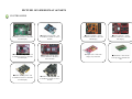
CONTROLLERS
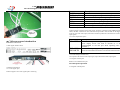
●LINSN Sending cards – will
be installed in the PC to send data
to LED Display
●LINSN receiving cards – will
be installed in cabinets to receive
the data.
●Liyan Controller – will be
installed in cabinet to control the
LED Display
●DBSTAR Sending cards – will
be installed in the PC to send data
to LED Display
●DBSTAR receiving cards –
will be installed in cabinets to
receive the data.
●Graphic card – control the
●Z-DEC Sending cards – will
be installed in the PC to send data
to LED Display
●Z-DEC receiving cards – will
be installed in cabinets to receive
the data
display way of monitor
●Xixun Controller – will be
installed in cabinet to control the
LED Display
●Hub board – insert on the
receiving card to distribute the
data
LED 最佳解决方案全球供应商
The Global Supplier of Best LED Solutions
CABLES
●RJ45 – internet cable – connect
the LED Display and sending
card to transfer data
●USB – connection cable – to
connect the sending card and PC
●Module data cable – to connect
and transfer the data between
modules
●Data cable inside cabinets – to
connect receiving cards and
modules, then to transfer the data
from receiving card to every
module row;
●DVI Cable – to connect the
DVI connector and sending card
connector
●VGA cable – to connect the
VGA connector and sending card
connector
●Power cable – to connect
cabinets
●Power cable – to connect the
power supply with modules
●Aviation power cable and net
cable – to connect cabinets
●Aviation hat – installed on
power cable and net cable to
connect cabinets
LED 最佳解决方案全球供应商
The Global Supplier of Best LED Solutions
INSTALLATION TOOLS AND ACCESSORIES
● M4 X 10MM screw –
fix modules to cabinet
● Allen screw :
①M10 X 60 ②M10 X 25, using
with connecting plates to fix
cabinets
●Key for cabinet – open and
close back doors of cabinet
●Connecting plate - ① Z-plate:
120 x 80 x 60 ② flat plate: 120 x
120 ③ flat plate: 120 x 60
●Multimeter – measure current,
resistance
● ① Hanging beam
② foundation beam – using
together for hanging screen
●Open end spanner –
installation tool
●Hex wrench – installation tool
●Screw driver – installation tool
●Truss – support and hang the
screen, for rental hanging screen
LED 最佳解决方案全球供应商
The Global Supplier of Best LED Solutions
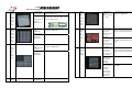
PRODUCT AND PARTS
PERIPHERAL DEVICES
●Face of the cabinet
●Rear of the cabinet
●Face of the module
●Rear of the module
●Power supply – installed inside
each cabinet, switch AC 220V to
DC 5V
●Electric fan – installed inside
each cabinet for ventilation
●Industrial personal computer
(IPC) – control the led screen
●Video splitter – video image
segmentation
●Video processor – connect to
other signal sources, process
video
●Power distributor box – to
supply electric power for led
screen
LED 最佳解决方案全球供应商
The Global Supplier of Best LED Solutions
MANUALS AND CD
●LED control system manual
●LED studio user’s manual and
CD
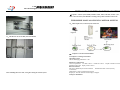
Plywood case
Flight case
2. Quantities and appearance of cabinets
The quantities of cabinets you get should be the same as the quantities we delivered. Please
check whether it is the same or not. The packaging you get should be intact. Please check
whether the packaging is stained or opened without permission, and confirm it is exactly the
goods you ordered or not.
3. Logo for packaging
Customized logo for flight case, and the mark for plywood case is as follow:
●TOP TECH software CD
●Driver disk – to install
hardware drivers for the
computer
INSPECTION
We, TOP TECH, sincerely suggest every esteemed client does the inspection as three steps
when get the screen. :
Step 1, check the outer packaging
1.Types of packaging
Usually there are two options for packaging: plywood case and flight case
A、Order No.
B、Cabinet serial number
C、Net weight, gross weight, and measurement of packaging
D、Mark which comply with GB191 standards: up, guard against damp, stacks layer, handle
with care
LED 最佳解决方案全球供应商
The Global Supplier of Best LED Solutions
LED DISPLAY INSTALLATION
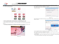
Step two: Open the Spare Parts case and check the packing list
1、
Open the Spare Parts Case
Take out the packing list in the case, pls be careful when open it, if it’s wooden case, pay attention to
aviod ruining the valuable goods inside.
2、 Check the delivery note
Please check the goods, make sure what you received is the same when shipment, including
following information:
A:Screen:including the Cabinets, Modules, Switchses, Control Cards, DVI Cards, and other spare
parts:
B:Cables:including DVI Cable,signal cable,power cable, all flat cable, connect cable, and its spare
parts.
C:Control Software:Including install CD. Control system software and user manual(if by PC
shipped, the control system software has been already installed well in the PC)
D: Other spare parts: including spare Led Modules, LED Lamps, keys. Screws, instal steel
panels,external devices,etc.
E:Project related file: shipping quality inspection report, system connect disgram etc.
F:Free prepares: Toptech user CD, catalouge, toptech Led screen user manual etc.
1.Confirmation of Led Installation Type
Based on different application area of Led Display, dividing a variety of installation types,
including fixed installation, rental hanging, sports peremeter installation. Based on different
applicaton invironment of Led displays, dividing a variety of installation types as well. Clients
can choose installtion types and setting up mouting structure according to pratical situation(our
company can make steel structure chat for your reference). As follow focus on introduction of
Wall Mounting Type, Mosaic Type, Column Type, Building roof type, Mobile Type,, Rental
hunging type and Curve type.
1、 Wall Mounting Type
⑴General used for infoor and semi-outdoor.
⑵If active display area is small, that often will not leave access to maintain, remove whole led
display to repair or make frame folded-in-one.
⑶If active area is slightly larger, generally adopt front maintenance design(front maintance
design)
As for the order actual condition, each order shipped goods and quantity subject to the order final
packing list.
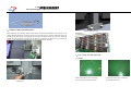
Step Three Casual Inspection
1. Check the cabinet appearance.
Check the mask color, damaged, cabinet back door open freely
2. Light up the casual inspected cabinet
A: Make sure Led Screen relation system, check its function
B:Check the uncontrolled dots, module breakage, or other hardware breakage risk.
After finished above three steps, you can staet instal job freely, thanks.
2、Column installation type
There are many types installation ,generally for outdoor advertising applications ,as follow::
(1)Single columum installation type:applicable for small screen .
(2)Double column installation type:applicable for large screen .
(3)Closed maintainance channel :applicable for simple cabinet.
(4)Opened maintainance channel:applicable for standard cabinet.
LED 最佳解决方案全球供应商
The Global Supplier of Best LED Solutions
4、 Building roof installation
(1The main point of the installation is wind-resistance .
(2)Generally installed with a tilt angle,or the module design with 8 degree oblique.
(3)Mainly for outdoor advertising application
3、Mosaic
installation
(1)The whole led display is embedded in the wall,display plane and wall at the same level.
(2)To adopt simple type cabinet design
(3)Enerally adpot front maintencance (front maintanance design)
(4)The installation is suitable for indoor and outdoor application ,but generally used for small pixel
pitch and area of led screen
(5)Generally used for building ‘gate ,building lobby.etc.
5、 Curve installation
The normall requirment :
●Screen’s lengthxwideth(birghtness):LXW
●Screen lengthW:the height of the screen
●Screen length L:the length
●The length of the screen could be initially setted by circumference of a circle and arc .divided
by the module length to determine the number of modules.
●For the circular screen ,divided by the numbers as much as 92 modules ,determined modules
numbers in a row according to the integer multiple of 2,3,4,5,6(Facilitate to the division of
cabinet,easy to production).The gradient of module is 2 degrees,generally,one module with 4
degrees only .so generally one completed and perfect round display is composed of 92
modules,and it is not better less than 60 modules.
●After determining the number of modules at a row ,the length of the screen can be devied.
●Screen length L=Module number*module length
●Screen area A=L*W
LED 最佳解决方案全球供应商
The Global Supplier of Best LED Solutions
●For non-circular screen(curve screen),that is simply divided as needs,like the cake cutting.
●The installation mount should be customed by the size of circular (curved)screen.
二、 LED DISPLAY INSTALLTATION FLOW
●Outdoor
fixed installation
LED display connection sketch map;
6、 Hanging installation for rental
(1)Screen size determined by common screen
(2)Hanging screen is not good on large size ,generally requests less than 6m*10m .except curtain
display.
(3)Top equipped hanging beam,bottom equipped bottom beam,hanging beam used for hanging
display.
(4)The types of hanging organ divided :gear wheel,cone rod,bolt.
(5)Gear wheel is expensive ,beautiful
(6)Cone rod price moderate ,reliable
(7)Bolt is cheapest ,reliable ,bother for assembly,not suitable for the case of repeated disassembly.
1、Prepare the installation tools
①
②
③
④
⑤
⑥
M10x60mm screew
M10x20mm screew
M10 Hexagon wrench
110x55mm connecting iron piece
110x110mm connecting iron piece
Strip iron piece.
LED 最佳解决方案全球供应商
The Global Supplier of Best LED Solutions
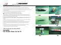
2、Cabinets connection and fixation
Bottom connection view
When beginning to install the cabinets please make sure that the substratum (steel structure) is fat
enough.The falt substratum can reduce the crevice (gap) between two cabinets. Otherwise, the more
load up, the greater the gap. After placing the firt series of cabinets on the steel structure, fasten the
cabinets by connecting the metal plate to the 40# tube (channel steel). However, do not fasten the
screw too tight, and then proceed the final adjustment to finish the assembly.
The full view after installation
3、Power supply cable and signal cable
Side view
3.1Cables
Short signal cable-CAT5, connecting
the receiving cards among cabinets
Middle view
Long signal cable-CAT5, connecting
PC and the LED scrern
LED 最佳解决方案全球供应商
The Global Supplier of Best LED Solutions
4、The installation and connection of the sending card
4.1The schematic diagram of the DVI card and sending card in the mainframe computer
3PIN2.5 mm2 short power supply cable,
connecting the terminal and the cabinet
3PIN2.5 mm2 long power supply cable, connecting
the LED screen and the power distribution cabinet
Note: L-brown wire, N-blue wire,G-yellowish green wire
3.2 Schematic diagram of connection
4.2Wiring diagram of the mainframe compute
LED 最佳解决方案全球供应商
The Global Supplier of Best LED Solutions
5
Wirng diagram of the controller
1、Tools for installation:power supply cable,network cable,hexagonal rod
2、Fixation of the hanging beam and cabinet
6The full view after installation
3、Embeding the hanging beam into the cabinets,from the top.and the fast enit
Illustration of rental Led display /of rental cabinet
installation
●
LED 最佳解决方案全球供应商
The Global Supplier of Best LED Solutions
4、Fix the cabinet to the hanging beam by fastening the lock catch
7、Pull up the Beam has been already installed and the first layer, then begin to install the
second layer.
5、Fix the Middle Lock of Screen to bind the Cabinet and Hanging Beam tightly.
8、Lock the relevant position up after installing the second layer.
6、Connect the neighbouring Cabinets in horizontal direction with locks.
9、The effect drawing of complete installation.
10、Connect the Power leads and Data leads according to the connector of the Screen
Body.
LED 最佳解决方案全球供应商
The Global Supplier of Best LED Solutions
DEBUGGING OF THE CONTROL SYSTEM
●Toptech’s control system mainly includes Linsn, Z-Dec, DB Star, Xixun, Lytec, pls
refer to the relevant System Manual according to the praticle situation of the order.
THE SIMPLE MANUAL OF LINSN CONTROL SYSTEM
一、Link Graph of PC, Control Sytem, and Screen
11、The full view of Screen Body after installation.
二、Computer’s selection and installation
2.1Computer’s running invironment.
Operating System
Chinese and Engligh Windows 7 /XP
After installing the Screen well, we begin to debug the control system.
Hardware Configuration
CPU: The pentium 4
2.4 GHz or above RAM:1G or above Graphic Card PCI-E socket:
Standard VGA512M display mode or above
Relevant Software
Microsoft’s Media Player-must be installed
Finaldecoder 2009 or above(fiercely
recommend)
OFFICE2011- must be installed if need word
Realplayer- must be installed if need display realplayer
2.2Step for installation
LED 最佳解决方案全球供应商
The Global Supplier of Best LED Solutions
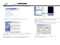
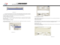
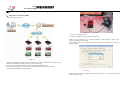
《LED Studio》software can be easily installed with the following steps:after inserting the LED
studio installation CD into computer cd-rom, you will see the installation interface(if not, select the
CD,and click it twice with mouth )
Picture 2-3
Picture 2-1
As shown in picture 2-1, select” install Led Studio”, begin to install its installation guide
As shown in picture 2-3, at the same time, the shortcut of “Led Studio” appears on the desktop.
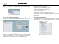
三、Special note and the setting of computer parameter.
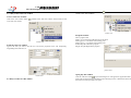
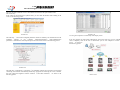
3.1Open the Setting of software
Click “Set” in the main menu, select and click the “software setting” in the down menu, the
dialog box of inputing the adminstration code, click ok after inputing the code.
Picture 2-2
As shown in picture 2-2, operate as the indication. Note: This is the Serial-Number-Protection
software, installation can’t be continued without inputing the correct serial number, the serial
number is “888888”
.
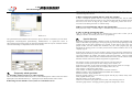
After finishing installing the software successfully, the “Led Software” Program Group will appear
in the Start/Program Menu, and click the “Led Studio” within this program group to run.
Picture 3-1
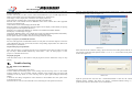
3.2 Play Window
There are 3 modes of Play Window: Choose lock to Led Screen, Many screens’
combination/synchronization, Freewill Set
LED 最佳解决方案全球供应商
The Global Supplier of Best LED Solutions
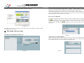
Locked to the LED screen
Locked the display window to the led screen area
Multi-screen assembly/synchronous
Choose screen-assembly/synchronous, and click the button of” assemble/synchronous setup” to
open the dialog-box of the multi-screen assemble//synchronous setup as shown in pic. 3-2
Picture 3-3
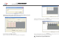
3.4Other setting ups
The software can restart automatically when it is fault: when there is something wrong with the
software, it will restart automatically.
Restart the software everyday: restarting the software in fixed setting time
Picture 3-2
Setting up at your will
Users can set up the number of the screen and adjust the size of the screen at their need, and click
the “refresh the screen number” to change the screen number when the change is needed.
The mouse is allowed to adjust the size and location
Back-up at regular time: it will back-up the displays at regular time
Record display time: it can record the display time and store in the document of play.txt.
Error pointing-out is unallowed: the window of error pointing-out will not appear during
display.
Exit verification: when clicking the exit button, it will appear a dialog window for you to
confirm.
The mouse is also can be used to change the location and size of the display window
The display window is always headmost
The display window will appear in front of any window, it will not be blocked out
The software is responsible for displaying the frame frequency
According to the different computer configuration, you can promote the display quality
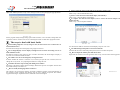
3.3 Set up automatically
The software has the functions as follows: it can be activated when the Window is started; loading
the documents automatically when activated; when starting automatically, it can display
automatically; when start manually, it can display automatically; switch the real image and virtual
image automatically; the mouse can hide/show automatically; automatic update the new software, as
the pic. 3-3 shows.
Picture 3-4
LED 最佳解决方案全球供应商
The Global Supplier of Best LED Solutions
四、Simple software operating steps
4.1Display videos
4.1.1 Open a new display window
Click the button of “open a new display window”
to start a new item of text and graphic window
and choose a “text and graphic window”
Picture 4-2.
picture
4-1
4.1.2 Setting animation display window
Setting the attribute of the program
Name : the name of the showing display
Frame: setting the width and the color of the frame is allowed.
Starting point X: the relative position X on the big screen.
Starting point Y: the relative position Y on the big screen.
Width: setting the width of the display.
Height: setting the height of the display.
Lock: lock the window to make it not move.
4.1.3 Open the display document
Click the “add document: button on the center-under point to open the dialog window.
To broadcast the animation file, all the media file (AVI/MPEG/ASF/WMV), and FLASH animation
file (SREAL PLAY) (RM) and so on is allowed in this display.
Open the file in any type above, show as pc.4-2
Picture 4-3
4.1.4 Set up the file attributes of the animation file
The file opened just now has been added to the listing, to choose the background color,
background picture and drawing methods of the background pictures. Three effect can be
chose.
4.2 To display the picture
4.2.1 Open a new picture and program window
LED 最佳解决方案全球供应商
The Global Supplier of Best LED Solutions
Click the button of “open a new picture and program window”, to choose the button of “image-text
window” to establish a new image-text window, show as the pc 5-1.
the right). Click the picture to open it. And the right lower part of the window will be as the
below shows.
Picture 4-4
4.2.2 Set up the image-text window
To set up the program attributes
Picture 4-6
Name: the title of this program
Frame: setting the width and the color of the frame is allowed.
Starting point X: the relative position X on the big screen.
Starting point Y: the relative position Y on the big screen.
Width: setting the width of the display.
Height: setting the height of the display.
Lock: lock the window to make it not move.
Picture 4-7
Picture 4-5
4.2.3 Open the displaying file
Click the button of “add the document” to open a file dialog window, and to choose the type of
image-text in the listings and open it ( when you choose the picture, you can preview the pictures on
4.2.4
Set up Play Picture Properties
The file of Open has been added to the list Just now, then, The following lists the file
option,you can select background color,background photo,backgrond Image Rendering,
A dozen special effects Available to choose,Speed,stay time,clearing effects,clearing speed.
LED 最佳解决方案全球供应商
The Global Supplier of Best LED Solutions
4.2.5 Insert background photo, Playing music and text.
Insert background photo
Starting Y: relative to the starting position X for big display
Width: Set up the width of the program
Hight: Set up the hight of the program
Click the Button,in the Open File dialog box. select you want to insert a background photo, Click
Open. You can also enter directly in the edit box background image.
Insert playing music
Click the button, in the Open File dialog box, select the music,then click Open.
4.3Play text .
There are six methods programs: a text window to play, play in the static text window, open the file
in a text file playback window, the window in the document text superimposed on a picture file
playback and inserted in the broadcast notification Play
4.3.1 Play in the text window
The window is not required, the text can be broadcast in the graphic window, this window is only a
simple Wending such as company name, welcome text, notices, etc. provide a fast input method.
New text program window
Click on "New window" button, in the menu, select "Text Window" to create a new text window.
Picture 4-9
Insert and edit text
Edit Text。Click the picture "add text" the button will appear "Text Edit" dialog box,In the end
of bottom edit box ,you can enter text directly write text,and you can copy into text. Also,you
can do type-editing, can set up the background, fonts, special effects, speed, stay time and so on
Picture 4-8
Set up text program window
Set up text program Property
Name: the name of the program
Frame: you can set up the width and color.
Starting X: Relative to the starting position Y for big display
Picture 4-10
After editing ,the text Close "Text Edit" dialog box, then ,the test will appear list it .
LED 最佳解决方案全球供应商
The Global Supplier of Best LED Solutions
Picture 4-11
If you want to modify the text, just select it and click the button, open the edit box will allow
you to modify . delete the texts,you can select remove the program button, remove text in order to
use the Move button. Click the button can be used to preview the selected text.
Picture 4-13
4.3.2Play in single-line text window
The window only can be welcome captions words, notices, etc. to provide one-way move titles,
these test to support a transparent display, which can be windows, including text windows and photo
of the video file
Set up single-line text window
Create new single-line text window
Open from externa file
Click the "create new window" button, in the menu, select "single-line text window" to create a new
single document window.
Select "External file" , click the button to open the file, the program can modify the dynamic
display during playback of a text file. You can set up action, backgrounds, fonts.
Settings up show property. there are two way input text, one is open from an Externa file, the
other is directly in the edit box.
Input Edit select "text"
Select the “text”, and then type in text that you want in the box below ,you can also set up the
action ,,background and fonts
Picture 4-12
Picture 4-14
LED 最佳解决方案全球供应商
The Global Supplier of Best LED Solutions
Click on the “new window” button
create a new “file window”
4.3.3 Play in the static text wondow
select “file window” in the menu to
Creat a static text wondow
Click on the “new window” button
a new static text window.
and then select “static text window” in the window to creat
Picture 4-17
Setup file window
Picture 4-15
Setup the satic text window
Type in the texts you want in the edit box, and choose properties below, like transparency,
Align,Background, and Font, etc.
Name: program name
Frame: you can setup the width and color of the frame
Starting point x: x-coordinate of the starting point
Starting point y: y-coordinate of the starting point
Width: setup the width of this program
Height: setup the height oh this program
picture 4-18
Picture 4-16
4.3.4Play text files in a file window
Open play files window
Click the "add file" button ,an open file dialogue box will appear.All supported formats are
listed in the list at the bottom of the dialogue box.Selecting text file or Word file from the above
file list,then click the open button to open it.
LED 最佳解决方案全球供应商
The Global Supplier of Best LED Solutions
That is because of the disconnection between the screen and the serial port cable,or they are not
connected well,please check it.
C.How to change the position and size of the play window?
In order to change the position and size of the play window,firstly,enter into the software
setup,set the position of the play window to "any position",then input the coordinate and size of
the screen,or use mouse to drag the play window to change the position and size of the
screen.For more details,please refer to "software setup"
D.How to run automatically and play the specified file?
Firstly,enter into "setup"---"software setup"---"automatic setup",then select the three options.
E. How to edit the existing files(.lsd)?
Picture 4-19
The opened file has been added in the list,now the option of this file is listed below,you can choose
background color,background picture,drawing methods,dozens of specials,four kinds of
effect,speed,staying time,and options of characters.(Remark:if there are only few words,file window
can be used.If editing is complicated,word file can be chosen)
Click on “open” button to open the file, and then select “allow edit” to allow you make
chanages to the files. For details, please refer to “programming”.
六、
Special function
Program( program document) consists of one or more than one program pages.
There are two kinds of program page: normal program page and overall program page. Normal
program pages are the main components of a program, so there may be many. They will be
played in order, one after another; there should be only one overall program page, played
throughout the playing process. It’s mainly used for fixed content’ broadcast, such as clock,
company logo,etc.
Program page consists of one or more windows, which is used to show the contents that users
want to play, like document, pictures, cartoons, multimedia segments etc.there are twelve kinds
of program windows; file window, text window, single line text window, static text window,
table window, timer window, data base window,DVD/VCD window, external software window,
data/time window,video line-in window, and geometrical graph window.
Picture 4-20
五、
Frequently asked questions
A、Warning of MCI system error when starting?
This is because the Windows Media Player has not been installed,please install it.Find a file named
Mpsteup2k.exe(for WIN2K/ XP/me),or Mpsteup98.exe(for Win98).Double clink to install.
B.Warning:can not find the screen system or transmission error.
File window: can play various files like words, pictures, cartoons, tables,etc.
Text window: used for quick inputs of short writings, such as notifies, etc.
Single line text window: to play single text window, such as notices, adverts etc. writings.
Static text window: to play static texts, like company names, titles, etc.
Table window: to edit and play table figures.
Timer window: for timing, supporting clockwise and anti-clockwise.
Database window: to play ACCESS database and ODBC driver database.
DVD/VCD window: to play DVD/VCD
External program window: to insert external program into the play window, mainly used for
small programs made by users.
Date/time window: to play date and time.
Video line-in window: to play signals from TV cards, video collecting cards, etc.
Geometric graph window: to display geometric graphs like straight lines, circles.
LED 最佳解决方案全球供应商
The Global Supplier of Best LED Solutions
二、Computer & Install
ZDEC SERVICE MANUAL
1.The chart of PC, system & LED
screen connection
Operating environment
●Operating system
Windows2000/XP Chinese and English version
●Hardware
CPU: celeron 2.4G or higher
Memory: 1G or higher
Graphics: 32M or higher
●Related software
Video decoder-compulsory (install special decoder when play RM or RMVB format file)
2.1 Install
《LED manager 2010》software is easy to be installed. firstly, to check whether the computer
has old version of LED manager tool, please un-install it of exist. Secondly, double click LED
manager file and then diadlogue popup, see fig 2-1, select “next” to start installing. When the
installation of 《LED manager 2010》is made, the “LED software” will appear in the
<start/program>, click to start operation after entering <LED manager 2010> in the program as
fig 2-2 shows.
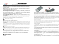
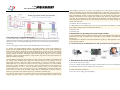
Figure 1-1 single sending card application
Solution introduction: in fig1-1, indicate compter, 2 indicate sending card, 3 indicate receing card, 4
indicate monitor. Sending card has 2 output port, U port & D port. Receiving card are connected in
series-wound condition, detector can be fixed behind U port or D port(Non-permit fix the detector in
both port, don’t fix detector is also acceptable). Detector is used for real-time monitoring
brightness,temperature and humidity of LED screen. The maximum equipments for each sending
port is 200.
Picture 2-1
LED 最佳解决方案全球供应商
The Global Supplier of Best LED Solutions
3.1 After computer operating system starts, right-click the desktop, then use the context menu
button to select the "Properties" item to enter the 【Display Properties】Settings dialog box.
3.2【 Display Properties】 in the pop-up , select【 Settings】 the most right page, then click on
the menu at the bottom right corner of the "Advanced" button, as shown in Figure 3-1.
Picture 2-2
At the same time, also on the desktop "LED management tool 2010" Shortcut: double-click it as
shown can also start the program.
2.2 Uninstall
《LED administrative tool》supply automatic install operation,
"LED management tool 2010" provides automatic uninstall, so you can easily delete "LED
management tool 2010" all the files, program groups and shortcuts, users can select from group
"LED software" "Uninstall LED management tool 2010 ", as shown in Figure 2-2, can also be
passed in the Control Panel Add / Remove Programs quickly unloaded. Click Uninstall, it will pop
up a dialog box asking whether to confirm the uninstall, click OK, the software will automatically
uninstall; the uninstallation is done in Figure 2-3.
Picture 2-3
三、 Special Notes, and computer parameter settings
This section with NVIDIA graphics as an example of the computer graphics set method. Video card
brand, different model, the setting method slightly different, note that this day only for reference,
please according to actual situation video card set mode.
In order to ensure the content on computer monitors and LED screens display the same content, we
want more than one graphics card output (typically VGA and DVI output) set to copy mode.
Generally monitor set to Slave Device, the display system set the master device. Set as follows:
Picture 3-1
3.3 In the pop-up 【[Plug and Play Monitor and NVIDIA GeForce6200】dialog box, select the
menu of【 GeForce6200 】menu, and on the left side of the additional menu, click "nView
display Settings menu, as shown in figure 3-2.
Picture 3-2
LED 最佳解决方案全球供应商
The Global Supplier of Best LED Solutions
3.4 In the pop-up screen has two options, including click "nView" options menu, select the copy,
and then save Settings, to return to main interface, as shown in figure 3-3
Playback window size must be set correctly, otherwise programming may only playback a part
or not big enough, the method of setting: Menu → Settings → Display settings, as shown in
Figure 4-1, you can select in the software to set lock display window position (the best choice
for this option, playback window and display exactly have the same size and position).
Left margin and up margin (X, Y) were set to (0, 0) to ensure that play window at the upper left
of the screen, width, height according to you the size of the screen to set, such as your screen
width and height is 512 X 256 point is set to (512256).
Step Two: New Episodes
Episode is the program's basic elements. Figure 4-2 shows the program toolbar, click the New
in the pop-up menu you can click the episode. File can contain any number of
button
episodes, delete button
is used to delete program and move button is used to move the
to change the current ratio of the display screen for
program. Zoom in and out buttons
easy editing.
Picture 3-3
Through the above, DVI has opened the signal output. Observe and identify the sending CARDS
state lamp instructions correct.
四、The
simple software steps
Step One: Set the playback window size
Picrure 4-2
Step Three: Set episode options
When new episodes of items or selected episodes of items, you can to set the display window
on the right episode option, as shown in Figure 4-3, episodes of options are available episodes
name, episode option, play time / the number and background music.
Picture 4-1
Picrure 4-3
LED 最佳解决方案全球供应商
The Global Supplier of Best LED Solutions
Step four: New Multimedia window
Episode is only a framework, it can contain any multimedia window. Click the New button to
select the multimedia window, as shown in Figure 4-4.
Picture 4-4
Width, height: media window height, width.
Transparency: the transparency of the media forms background.
Background transparence: on / off transparency
Maximize: media player window full of playback window.
Background image: The media window background image.
Background Zoom: The background image display window media format.
Background color: background color of the media window.
Frame Style: windows media frame style.
Frame Color: media window frame color.
Playback Options: used to guide the play times of media window or play time.
Views / Time: Enter the number of the media play times or play time.
Clip playback time of this set as a benchmark: the end of episode is based on the time of play
window, such as: there are ten episodes under play window, if the third player in the window
check this, then when the third finished, the program fragment under all players will stop
playback window.
Lock position: Locks the position of the media window.
Step Five: to set multimedia window properties
Step Six: Adding multimedia material
Each multimedia window can set the location, size, background, transparency and other properties,
as shown in Figure 4-5.
Each multimedia window that can be played simultaneously in different text, pictures, tables,
animation, video and so on. Twelve of multimedia material to choose from, as shown in Figure
4-6.
Picture 4-5
Specific instructions for each property are as follows:
Name: the name of the multimedia window, the name directory displayed in the editing area on the
left column, as shown in Figure 4-5 on the left menu bar. Left margin, up margin: the distance
between the left frame of the media player window and its left frame of playback window, and the
distance between up frame of media player window to its up frame of playback window.
Picturte 4-6
LED 最佳解决方案全球供应商
The Global Supplier of Best LED Solutions
Material file: The most important material. Including picture, video, flash,word and excel and other
formats of media files.
Test box: used to play text files, such as: Notice,advertisement text, you can add single-line text,
multi-line text and the word special flash effects( Default rate of 12 frames/sec)
Time display: Used to display time, include the clock display, timer time.
Audio spectrum: Including audio visual images and audio spectrum image
External video: Used external camera or SDK3000 video card to connect other video equipment
such as TV,VCD/DVD,VCR.
Custom Table: used to edit and display the tabular data
External program: For embedding the external program into the display window,mainly for playing
small programs user developed for themselves.
Data base: Use to display the database file. Include access database and ODBC database.
Web display: Used to display web pages.
Temperature /Humidity display: Use to display the current environmental temperature and humidity.
Instant Messaging: Used to quick a short text. Such as notification letter.
Screen capture: Used to record the current screen image inside the window.
Open the “LED MANAGER 2010” Click the hardware setting under “setting”,it includes all
the main setting of the screen( see figure 5-1)
Step 7, Set property of multimedia material
For each of the properties of multimedia material, we will point out in the later chapter. You need to
create multimedia from type upon needs, find the corresponding chapter,which can obtain more
detailed property information.
Step 8, Finish program production
After eight steps above, a complete program can be completed .If need more episodes just repeat
step 2 to step 7. When finished click the drop –down menu -> <file> Æ <Save project> or <save
project as> to facilitate the next use.
Picture 5-1
While entered into the” hardware setting” option, and at least one sending card and the PC USB
port correctly connected. Then input the words: “z” “d” “e” “c” it will comes out an password
window.(See figure 5-2)
Step 9,play program
Click the bottom <Play> in the control to start playing shows,<Pause> bottom and <stop> for stop
playing
五、
Trouble shooting
5.1 The whole screen Blindness
Solution:
1.Check the power supplyof the whole screen.
2.Check whether the indicating lights of the sending card and receiving card is in the normal
working condition or not. The normal working condition of the sending card is the green light
twinkling,red one keep blind .as to the receiving card one green light twinking,the other keep
lighting.
3. Click into the setting configuration of the software.To check whether the close option of the
screen has been chosen.
4.If all the above is correct. Then resend the screen connecting file. The operation as follows:
Picture 5-2
Input the password”168” and click the “ confirmation”bottom to enter into the “advanced
hardware setting” windows. (See figure 5-3) (Notice: <advanced hardware setting> is for
professionals only, the common user is not recommended.)
LED 最佳解决方案全球供应商
The Global Supplier of Best LED Solutions
Picture 5-3
Click the”Screen connection” bottom to enter into the screen settings (See figure 5-4) ,the screen
connection mainly sets the connecting conditions to the screen. If stored such files before. Then you
could click the button” load from file” to load it from the exist file.
Picture 5-5
Checking the transmitting card status if have unusual status. THen click the “Start detection”
button (Figure 5-5) to check whether there is default data appears.
Picture 5-4
5.2 Part of the screen displays unmoral
Solution: Click the “Device status” under the setting option, see under figure(5-5)
Picture 5-6
Observe if the data appears wrong. If discover the data appears wrong. Then please check the
connection between the current receiving card and the closed ones.
六、Instruction of special functions
LED 最佳解决方案全球供应商
The Global Supplier of Best LED Solutions
6.1.Start out the LED manager Tool 2010
Start out the LED manager Tool 2010, as in picture 6-1 below:
Picture 6-1
6.1.2 Open the software for spot to spot correction
●After the set up of the LED display, click the"display calibration" under the "tool" menu list, then
comes the "display calibration interface" as in picture 6-2
Picture 6-2
6.1.3 Check the calibration result
At the "display calibration", choose "Open",then click "save to LED dispaly" as showed in
picture 6-3. Then you can see result of the spot to spot correction .
If the result of the spot to spot correction is not good, it can be cancelled. Choose "close", click
save to the LED display. Then the calibration result disappear.
Note: If you want to save the result of the calibration, you need to choose "Open", then click
"save to LED dispaly". At this time, the display shows the effect after the calibration. Then
choose"exit".
LED 最佳解决方案全球供应商
The Global Supplier of Best LED Solutions
Instruction: Environmental monitoring equipment has its sensor of temperature and humidity
and also the illumination intensity probe. The sensor of temperature and humidity has shield to
protect itself from the wind, water(Rain). So it can be install at the outside of the display.The
intensity probe is also protected from the wind and water and usually installed at the
decoration edge part of the display, at the direction where the LED display faces.
6.2.2 Software Operation
After connecting to the environmental monitoring equipment and the installation of sensors,
open the software LED Manger 2010. Click the "Environmental monitoring" under the Menu
under the "Set Up" to enter the interface as in the picture below.
Picture 6-1
6.2 Environmental monitoring
6.2.1 Installation Instruction
At the page of "Environmental monitoring", the software will show the specific data of present
illumination intensity , temperature and humidity. Besides, if temperature and humidity window
has been added to the broadcasting program, the real-time parameter will be also showed on the
LED display.
At the page of "Environmental monitoring", click the"Monitor equipment " button and the data
can be set up for the Environmental monitoring equipment as in the picture below. The setting
of the port for the sending cards which connected to the environmental monitoring equipment
shall be proper, or the data can not be collected by the software in the right way. Besides, from
the interface, we can see: the suggested range for illumination intensity probe is 0~4000Lux,
for temperature sensor --10~60℃, humidity 0~100%RH.
LED 最佳解决方案全球供应商
The Global Supplier of Best LED Solutions
So according to real needs, the data for the "sampling rate" can be set up as 1s, 5s, 10s, 30s, 60s,
300s, 600s. This data decides the update frequency of the software for illumination intensity,
humidity and temperature. For example, if 600s for the sample rate is chosen, then software
will update the data of illumination intensity, humidity and temperature every 600 seconds and
begin automatically control for the brightness for one time. The default number is 10s.
The software interface offers "allow the automatic adjust on brightness" reselection. If this item is
chosen, in condition the software detects the environmental monitoring equipment, the brightness
will be adjusted automatically according to the illumination intensity. If this item is not chosen, then
the software only show the illumination intensity and will not do the automatically environment
brightness adjustment . The option of "allow the automatic adjust on brightness" is as default.
The software interface offer four items: "Minimum brightness for LED display", "Maximum
brightness for LED display","Present brightness for LED display","Sensitivity"
z
"Minimum brightness for LED display" means the Minimum brightness (can not be less
than this one ) for LED display when the brightness is automatically controlled. The
Maximum is 100, the minimum 1(only integer between 1 and 100, other numbers are not
allowed). The Minimum brightness for LED display is as put in.The default number is 50.
z
"Maximum brightness for LED display" means the Maximum brightness (can not be more
than this one)for LED display when the brightness is automatically controlled. The Maximum
is 100, the minimum 1(only integer between 1 and 100, other numbers are not allowed) .The
Maximum brightness for LED display is as put in.The default number is 100.
z
"Present brightness for LED display" means the brightness of the LED display at present. It
shows the present brightness of the LED display in automatically control and is limited by the
"Maximum brightness for LED display" and "Minimum brightness for LED display". It is
between the two.
z
"Sensitivity" offers 5 grades from 1 to 5. This decides the range of the illumination intensity
the LED display can adapt to the outside environment. Please check the follow table and graph
below:
Sensitivity
1(the maximum)
2
3(Default)
4
5(th minimum )
Range
0~4000Lux
0~2000Lux
0~1200Lux
0~800Lux 0~500Lux
accordingly
The instruction order for the Auto brightness adjustment(auto control of the environment
brightness), timely brightness adjustment(timely instruction clock):
z
z
Whether the auto brightness adjustment or the timely brightness adjustment start or not,
the manual brightness adjustment can be done.
When the auto brightness adjustment is on, the instruction of timely brightness
adjustment will no long work. The auto brightness adjustment comes first.
6.3 Optical fiber transmit
As in the graph as follow, the equipment 1 represent the computer, 2 the sending cards, 3
receiving card, 5 the optical electricity commutator. The equipments are usually connected by
the cable CATS-5E. The communication distance is 100 meters. When the distance is more than
100 meters, the Fiber is suggested for communication: use the cable CATS-5E and
optic-electrical commutator to connect the two equipments. Connect the optical-electrical
transmitters with optical fiber cable. The Multi-model Fiber Optic can communicate in an
distance within 500 m and for Single Fiber Optic,within 10 km. Additionally, the communicate
distance for any of these equipments can be increased by connecting the optic-electrical
commutator to the exterior.
LED 最佳解决方案全球供应商
The Global Supplier of Best LED Solutions
SIMPLE INSTRUCTION BOOK FOR DBSTAR SYSTEM
一、Working Diagram for Synchronous system
The connection for the receiving card in the display
二、The computer and the installation
Main Board: with one empty insert slot, at least one USB port available
Hard discs: at least 100M space left after the installation of the operating system
Memory: at least 64M
CPU: better than Pentium 300MHZ
Graphic card: Standard VGA 256 display mode or more advance
Software environment: windows95/98/NT/2000/XP/VISTA
The Media player of Microsoft must be installed
The office 2000 must be installed if word files will open
Real Player shall be installed if real player files will be installed.
Any computer reached the above requirements is suitable for the control work
2.1 Installation of Graphic card, Main control card
三、Notice
Turn off the power, pull the plug out and open the main framebox
Insert the graphic card into the VGA slot
Insert the main control card into the PCI slot, as in the below picture showed:
3.1 When finished the installation, pull out the net cable and turn on the LED screen. If it is an
black screen, then the connection is right. If there are some bright points or lines, then the
connection of the system do not connect well.
3.2 Please choose the net cable of good quality, or the communicate distance will be influenced.
四、The set up of computer parameter
The first step:
LED 最佳解决方案全球供应商
The Global Supplier of Best LED Solutions
MBI5026 ,MBI5024,TB62726,TB595,MBI5030,MBI5039,MBI5042,MBI6030,MBI6020,DM4
13,LPD6803.
五、Simple software operating steps
Double click the icon of XMplayer,and entering the software interface after setting up the
foftware.
The second step:
The simple understanding :
Some problems should be noted when setting:
Sending card setting:
●It should depend on the display's resolution,when setting the output area of the image
●Timing instruction means executing the corresponding operation at the specific time.
Receiving card setting:
●The refresh rate setting, as the below situations:
Photographing by camera,without flash picture:above 600Hz.dual color:60-75Hz
Full color effect indoor :180-600Hz,outdoor:300-1200Hz
●Gray level setting:
Dual color 256,indoor full color 4096,outdoor full color 16384 will be ok.
●The selection of driving chip:
DBT-Q2007 the chips of the receiving card support: MBI5026,MBI5024,TB62726,TB595,MBI5027
DBT-Q2007 the chips of the receiving card support:
The process of program recording
The first step:setting the size of the broadcasting window.
The size of the broadcasting window must be right,otherwise the program will show one part or
not big enough,And there are 2 setting methods:
LED 最佳解决方案全球供应商
The Global Supplier of Best LED Solutions
1.Setting the size of the broadcasting window at random according to customer's requirement,
The specific procedure is as following:
suitable one,the click confirm button..
According to the requirement, selecting, left, top, width, height,then click confirm button.
Click new button,like the below picture
2.The customer binds the display,can get the size and location of the display automatically,the
specific procedure is as following:
Left click LED screen,and the attribute list will be displayed.
Clicking the confirm button will be ok.
The second step:establishing new program list
After setting the size,will appear a window like that:According to your own needs,choose the
LED 最佳解决方案全球供应商
The Global Supplier of Best LED Solutions
The third step:adding the program material.
Left click "program"to display the attribute list,then setting.
The forth step:setting the program material option
Left click "subprogram"to display the attribute list,then setting.
According to the requirement, modifying the property after adding the material.
Like the below picture.
Left click x"program window" then setting,(x)means the serial number of the subprogram under the
subprogram,like the bellow picture:
Left clink LED screen to show attribute list.
The fifth step:clink save button after finishing the program editing.
The sixth step:broadcasting the program.Clink the play button in the tool
bar,pause,or stop button.
LED 最佳解决方案全球供应商
The Global Supplier of Best LED Solutions
六、Basic fault and eliminate
1. Interruption of the connection
XI XUN BRIEF MANUAL
一、System connection
The specific representation is :
1.
2.
3.
Unsuccessful parameter sending and connection interruption will be suggested.
Failure to find the control card
The interface of the software fails to adjust,which means under gray status.The software<LED
control equipment list> has no main control icon.
1、 Hard ware connection
Hard ware connection as show in image 1-1 in below:
Solutions for probably way to solve problems:
1. Pull in and out USB wire again
2. Change USB wire
3. The equipment manager checks the equipment connection:
4. The computer is confirmed without virus.
5. If it is embedded ,Maybe the slot loose or PCI too dirty. Please insert again or use eraser to
clear PCI interface.
2 . No-Signal output
The specific representation is:
The pilot lamp in the net mouth of the control car is not bright
Solutions for probably way to solve the problems:
1. < XMplayer> of our company has not been installed and please determine to install.
2. Failure to open the FPD of the display card.
3. Right click my computer on the desktop->propertyÆsettingÆseniorÆdisplay---FPD
4. Incorrect resolution mode:
The specific representation is: The screen flashes or under uncontrollable status. Troubleshooting
method. Adjust the current resolution of the computer to be in accordance with that of the control
card.
7.Special function description:
Brightness sensor, temperature and humidity sensor.
Function: Adjust the brightness automatically and react led display temperature.
The connection schematic diagram is as follows:
1.
2.
3.
4.
Picture 1-1
Connecting control card with Hub card by flat cable firmly.
Connection Hub card JI port with input port of led screen by flat cable
Accessing to power line and network
After control card on power, all indicators (Power, network and working) will turn on and
blinking which means the control card will operating normally.
2、Connection diagram of computer and control card
Computer and control card of the display is connected by network cable, as shown in the
picture 1-1 and 1-2
LED 最佳解决方案全球供应商
The Global Supplier of Best LED Solutions
After installing successfully, it will appear the shortcut ”lededitor”, then double click it and will
start the software.
2.2、Set up of LED set 2.0
The software parts of led display from our company have already been set ok, and the install
steps same to software install of lededitor.
三、Important notice and set up of computer parameter
1、Set-up of computer IP address
Picture 1-2
二、Computer selection and set up steps:
If led set2.0 detects IP address automatically, this step can be omitted. If not, it need to set up IP
address in the computer manually
Right click “Network Neighbourhood”, choose “Property”, open “network connection”, then
right click “local connection” icon, choose “Property”, and open:
1、 Computer selection:
Operating system: simplified Chinese, traditional Chinese, English WINDOWS XP
Hardware configuration: CPU; Pentium 600HZ above; Memory: 512M; VGA Cards: Standard VGA
256 display mode above
Other software: media player of Microsoft company is needed.
2、Set-up steps: LED set 2.0 and led editor
2.1、Put the reinstallation CD of Led Editor into the CD-ROM, and it will appear the installation
interface,(if it does not appear, pls choose this CD and double click the CD), as shown in picture 2-1.
then choose the item of “install LedEitor”, and operate it according to the screen instruction.
Connection as shown in the following picture:
Picture 3-1
picture 3-2
In the picture of 3-1, start to set up according to the steps. Click “property” icon, open the
following message box, as shown in the 3-2 picture, then single click “ok”, and finish the set up.
Pls notice that IP address subjects to 192.168.0.210.
2、Review LED display IP address in the Led editor
In the software of led editor, click “help” in the menu, open the follow window, as shown in 3-3
and 3-4 picture:
Picture 2-1
LED 最佳解决方案全球供应商
The Global Supplier of Best LED Solutions
四、Operating of simply software set-up
1、Open software set-up
Single click “setup” menu in the main menus, and choose “software setup” in the pull-down
menu and click it, as shown in picture 4-1
Picture 3-3
Picture 4-1
2、Software display setup
It can set up the item number of editable and browse item, usually the number is 1
The width and height of led display: it is used for editing item numbers and the size of browse
window
3、Telecom parameter set up
Choose telecom mode: single use mode and multi use mode
Picture 3-4
It can check IP address of led display in above picture 3-4
picture 4-2
LED 最佳解决方案全球供应商
The Global Supplier of Best LED Solutions
4、Default parameters set up
6、How to check the sent program and operate the diary of big screen?
Open item “default parameter set up” in the message window to set up the program page parameter.
Menu—help—check communication diary
7、How to search the IP of connected led display automatically?
Menu—help—reach IP address of led display
8、If computer has multi network adapters, how to choose the network adapter of led
display telecom?
Menu—help—check computer IP address
Picture 4-3
Set the programs totally through setting up the width of borders, color of borders, background color
of window, font size, and font color. It also can change this items to make other programs window.
五、The ways to deal with basic faults
Picture 4-4
1、When making single line word by using text box, the font can not be in vertical center or
lack of half character?
Pls choose the IP address connected with led display, and press icon “sure”
Pls make the font height one word high by using single line test box.
9、The added background pictures can not been deleted?
2、The 32 height display can not display 16 height font in two lines when using text box to
make multi-line words?
Pls delete all the routes of the background pictures, then it can delete the picture.
Pls make the words by using static text box. If window has border, the actual height of display is
two times of 32 minus the width of borders.
10、How to adjust the window place and the size fast?
Right click the window, and it will appear the menu set up, as shown in the following picture:
3、The window size can not be changed by moving the mouse?
Pl check whether the window is locked or not, if locked, pls open the lock in advance, then can
change the size by mouse, or by inputting the numbers to change the size.
4、Sometime the effects of previewing and making is not similar?
Pls subject to the showing effects of the led display. Because the preview of computer software does
not include timed preview and so on.
5 、How to modify the language kinds of software?
This software can recognize the language according to different operating system automatically. If
the operating system is English, the software only can run in English. At present, this software
supports three langue: simplified Chinese, traditional Chinese and English.
Picture 4-5
LED 最佳解决方案全球供应商
The Global Supplier of Best LED Solutions
五、The explain of special functions(wireless project)
1、The project of wireless GPRS
1.1 System topology picture:
Picture 5-2
1.3 The ways of software set up
Lededitor configuration steps are listed as in following:
Menu—set up—software set up—telecom parameter: choose multi-use mode, input the
password (default password is 888)
In the GPRS mode, choose IMEI telecom ways of terminal configuration, as shown in the
following table:
Picture 5-1
1)The user computer and ADSL router is connected by standard network cables, ADSL router is
connected with Internet by telephone, and also can by other ways.
2) Control cards and GPRS modules are connected by 232 communication.
3)Control cards and display are connected by common transfer boards and planar cables.
1.2 Hardware equipments connecting picture:
Picture 5-3
Open the message window ”GPRS terminal IMEI configuration ”, and set up the IMEI. Just as
shown in the following:
LED 最佳解决方案全球供应商
The Global Supplier of Best LED Solutions
The setting of model H7210 is as the following interface
Picture 5-4
Click “add”. Add a terminal user, and make the setting. The interface is as follows:
Picture 5-7
After setting, click OK to finish the setting for IMEI of GPRS terminal. After configuration,
click “send programs” to get the sending program interface, and finish the configuration of
GPRS communication scheme. As the following picture:
Picture 5-5
Note: Click “F5” to show the detailed terminal information of GPRS, and there is the option of
another GPRS model H7210. Choose according to your request (choose one in two), as the follows:
Choose M-GPRS and the do the setting as the following interface (Note: the user does not need to
change the content)
Picture 5-8
Note: Everything is ok if it is in China. It needs to change some parameters if it is out of China.
Please refer to the update and configuration for M-GPRS DTU in XIXUN LEDeditor9.0GPRS.
Picture 5-6
LED 最佳解决方案全球供应商
The Global Supplier of Best LED Solutions
2. Wireless RF scheme
2.3. One computer controls one controlling card connected to the RF wireless module
2.1. System topology diagram
The configuration steps for the LEDeditor are as follows:
Menu-setting-software setting-communication setting: choose stand-alone mode, and the RF
communication mode
Picture 5-9
1. The user’s computer and the wireless RF module are connected through 232 COM
2. The controlling card and the wireless RF module are connected through 232 COM
Picture 5-11
The connection of wireless RF for the display is the same as the ordinary connection for the
display as follows:
3. The controlling card and the display are connected through the universal transferring card and the
data line
2.2. The connection diagram for the controlling card and the RF wireless module (the setting is done
in the factory, and it just needs to be connected to the controlling card directly)
Picture 5-12
2.4. One computer controls one controlling card connected to many RF wireless module
The configuration steps for the LEDeditor are as follows
Menu-setting-software setting-communication setting: choose many computers mode {input the
password 168}
Choose COM (458 or RF)as the communication mode, and configured the related parameters
for the COM, and the ID list for the display, as the following picture:
Picture 5-10
LED 最佳解决方案全球供应商
The Global Supplier of Best LED Solutions
Picture 5-13
Configured the ID list for the display as the following picture:
Picture 5-16
3.1. The system structure is as following picture:
Picture 5-14
Can find the ID of the controlling card through the following steps: Menu-setting-hardware setting
Picture 5-17
The brief description of the communication principle: LED controlling card connect to
LEDeditor service center in the outlaying controlling computer via the parameter of the domain
name, to build up communication line.
Picture 5-15
The picture showing sending diagrams under many computers mode through RF:
LED 最佳解决方案全球供应商
The Global Supplier of Best LED Solutions
Example: Controlling the display in location B through the computer in location A
Preparation: apply for a dynamic domain name on the website: http://www.oray.com or other
supplier for the dynamic (like alahover.gicp.net)
Location A:
1. LED display
2. A controlling card of XIXUN Series L
3. 3G router, Internet card of CDMA or EVDO3G
Note: The 3G router and the LED intelligent controlling card are connected through the cable, and
they are in the same Internet phase.
Location B
1.
2.
configuration, please make sure that the controlling card is connected to the 3G router
through the cable.
The second step:
In location B, (2) configured the transferring rule in the router setting
Input the address of router LAN (like 192.168.81) in the browser. Land on the router, and
transfer the data of 31297 ports to (1) the IP address of the controlling computer like
192.168.81) in the transferring rule. Like the following picture:
Note: the service port is 312979 (this is fixed), if (1) the LAN of the computer is complicated,
please ask the administrator to help with the setting. For example, if the port is forbidden by the
administrator, please ask him to open it.
One computer
Router ADSL connected to the internet
Construction operation steps:
The first step: Use one computer with LEDeditor software in location A to do the setting (4)the
related parameter of the LED controlling card, refer to the following picture:
Distribute a domain name or IP address of computer server for the controlling card. Open the
LEDeditor software, Menu-setting-hardware parameter setting-input password- as the following
picture:
Picture 5-19
The third step: In location B, land on the applied dynamic domain name (there are two ways,
and you can choose either of them).
The first way: Download the software offered by the supplier to the (1) computer, and land on
the domain name, as the following picture:
Picture 5-18
Note:
1.
2.
3.
The user can apply for 2 dynamic domain name, one for main domain name (like alahover.
Dyndns.org)(It is advised that 2 dynamic domain names should be from two different
suppliers)
The display helps to remember the name, and helps the user to remember and recognize the
display controlled by the controlling card.
If there is static and fixed IP address in the WAN that the controlling computer connect to,
please use the server IP function to specify the static IP address that you own. After the
Picture 5-20
LED 最佳解决方案全球供应商
The Global Supplier of Best LED Solutions
The user can land on both the server’s main domain name and also the spare domain name:
The second way:
If the router has the function for dynamic DNS, you can make the domain name landing in the
router, as the following picture:
Picture 5-21
The forth step : ①Choose the configured parameters which are needed by 3G communication in the
LedEditor
software
in
the
computer
,Menu-Setup-Software
setup-communication
parematers—multimachine mode-input the password code:888-As shown in the following picture.
Picture 5-23
3.2 Using one computer to control many LED display screen
If use one computer to control many LED display screens, the setup way of every controlling
card is completely same as the one of which when you use one computer to control one
screen .,As shown in
the following picture
Picture 5-22
The fifth step: Configuration is completed ,①the LedEditor software can search the accessed LED
controlling card customer automatically,and develop programs and switching the screen, Calibrate
the clock ,adjust the brightness and the execution of the other instruction。 As shown in the
following picture:
Picture 5-24
LED 最佳解决方案全球供应商
The Global Supplier of Best LED Solutions
LIYAN MANUAL
Shown in the following picture:
Connecting diagram of the computer and the system and the diagram of the
computer and the LED display screen:
一 、The pc upset and choose:
Running CL2005 system needs the support of Microsoft Office 2000 or Microsoft Office XP. We
adopt you to run it under Windows XP and Office XP .
1.1 Intall : Hardware configuration: CPU:Above Pentium 300MHZ .Memory :64M Video
Card.Above Standard VGA256 display mode
二、 Setup the computer configuration
Communication :
In the Main Menu :click Ste up Æ Communication , then there will be a communication setup
window .
In the “Mode” menu,Choose serial communication、 Ethernet or modem.. Usually, Can use
Serial communication mode.RS422 or RS485 network model can be grouped in the serial
communication.
Setup the screen’s specification :
In the main menu of CL2005,click ”Set up”-Ædisplay screen, There will be the screen’s
specification setting up window .
If using the serial communication mode,the computer and the controlling card have been
connected ,and they have been connected to the power supply .then we can use Automatic
Searching function to decide the specification the serial communication port of the connected
display screen and the computer , communication speed and display screen .
三、Operation steps of easy software:
Click “start” ,then you can install the management system of CL2005 communication screen into
the computer
1.2 Running
In the menu of Start, choose ProgrammeÆ CL 2005 communication management
systemÆCL2005 ,then you can startup CL2005 communication mamagement system ,
In the file selection area , select the drive, folder, and then in the file name lis, double-click the
file name ,which you want to upload, then the selected file name will appear in the " send to the
screen’s picture " and "picture playback order".
There are five buttons under the "send to the screen’s picture "item .Edit, Delete, .Make/Cancel
the Clock background, Input the words directly and Play immediately.
LED 最佳解决方案全球供应商
The Global Supplier of Best LED Solutions
DELETE :Choose one picture or files in other format, then click DELETE button , then can delete
the file from the send to the screen’s picture item. This operation cannot physically delete the files
stored in the computer.
EDIT : Choose one picture of files in other format , click EDIT button , then the associated Edit
program starts automatically. then can edit the file .
Make/Cancel the Clock background: If the chosen file is in JEPG format , then the file can be
used to the background for the showing time ,safe days, temperature, humidity and so on .User can
choose the main menu “Tools”Æ Setting the clock layout, then can arrange the showing place of the
above shown comments,( Regarding to the Chapter 6).This function is especially suitable for
situation the big size date ,time or temperature , humidity or safe days
INPUT THE WORDS DIRECTLY :Input the words directly through the keyboard or Copy ,or
Paster operation.
PLAY IMMEDIATELY :Click” Play immediately.” Button , the comments shown in the View and
Edit window can be sent to the LED display screen to play .immediately .When it is finished ,the
LED display screen will return and continue to play its original program .
四 、Basic trouble shooting:
●The procedure of End “ Change scanning way” :
When user change the Scanning way ,Due to unintentionally close the power supply of the
controlling card or the CL2005 Program , the changing procedure is end, then cannot find the
controlling card .
Solution : choose the communication port in the Set up menu, and the type of the card , then choose:
ToolsÆControlling card set up -ÆInput the password Æ Search -Æ Delete ÆLast CPLD program
failÆConform.
●Communication initialization is failed
Solution : Check whether there is another program occupying the selected communication port of
the program ..If necessary, run the CL2005 program to send the data after restarting the computer.
●There is a pause in the final scene of the Continuous moving left text
The enter into way of the first act is different as the one of the last .or there is residence time, or
there is no sign to follow the last act closely
Solution: Make the moving effect of the first act same as the one of the final act , Or add a blank act
after the final act. Or make the moving effect of the final act same as the one of the blank act.
五、Specific function
Rf control:
Remote controller has many function, it can choose 10 image at most from 90 images , and
these 10 images can be played without stop, It can adjust the playback speed , it can adjust the
brightness of the screen. Note : you need to use CL2005 software to upload character
dot-matrix database before many operation begins.
Remote control operation need the cooperation of the remote controlling receiving board .The
CPU chip of the remote controlling receiving board will translate the keys of the remote
controller into some communication orders of the CL2005, then send the orders to CL2005
controlling card through serial port..
Operation method of the multiple choice remote controller .is as follows:
1 Adjust the brightness
When you press down the CALL key , the brightness of the screen will be improved to a higher
grade. When you press down CALL key once it is the eighth grade , the brightness of the screen
will be returned to the first grade .It changes circularly in this way.
2 Choose the picture
A 、Press Exit key , enter into the process of choosing the picture. During the process , press
Exit key again , you will cancel all options, and get back to the original chosen contents to
playback.
B 、During the process of choosing the pictures, the display screen will show “figure XX”
words, it indicates that which picture is displayed currently, Now, you can press the Number
keys to choose other pictures.
C 、If the picture ,which is shown by the input Number keys, is valid, then it shows that the
screen will load this picture. Now, you can press: ADD key, to change the entering rate of the
picture circularly.
D 、After loading the picture, if you are sure that you want to put this picture into the new
playback sequence ,pls press”*’ key, Now , the screen will still show the selected picture just
now .but the prompt text will be “figure —“,it shows it waits for the new input .
E 、If the entered Number exceeds the number of the effective pictures, the prompting of the
screen will be :figure ---“ also ;
After choosing the pictures, which need to be playback, press”#” to save, the screen will start to
playback in the new sequence.
LED 最佳解决方案全球供应商
The Global Supplier of Best LED Solutions
THE INTRODUCTION OF THE SYSTEM AROUND THE SCREEN
一、 Multi-function card connection diagram
LED 最佳解决方案全球供应商
The Global Supplier of Best LED Solutions
Port name
V1~V2
DP(Display Port)
YPbPr
VGA
DVI
HDMI
SDI/HDSDI(IN)
Description
2-channel PAL/NTSC composite video input
1-channel Display Port digital SD/HD signal input
1-channel SD/HD component signal input
1-channel computer analog signal input
1-channel computer digital signal input
1-channel digital SD/HD signal input
1-channel digital video signal input(HD digital video)
1.2.2 Audio input
LVP601 supports 5-channel stereo audio switch. Of which, 2 channels are DP, HDMI and SDI
audios, the other 2 channels are AD1, AD2 external input audio. AD1 and AD2 can be mapped
to the any one of all video inputs, and will be switched synchronous to the selection of video
input signals.
1.2.3 Video output Description
二、Video processor
1.Hardware connection
introduction
Port name
VGA OUT
1.1Rear signal interface frame
DVI OUT 1 /
DVI OUT 2
Description
1-channel analog RGBHV signal output, it can be connected to a
local display device and used as monitor (it is strongly
recommended to use this port when operating and setting
LVP601+).
2 same DVI digital graphic signal output, it can be connected
with external LED transmission card or LED transmission box
1.2.4 Audio Output (AUDIO OUT)
Corresponds to the selected video input signal, output this channel audio input signals.
1.2.5 Signals of other parts
RS232 serial communication port
2.Frontal panel operations
1.2Interface introduction
1.2.1 Video signal input
LVP601 support 8 lines video signal input as following
2.1 Diagram of frontal panel
LED 最佳解决方案全球供应商
The Global Supplier of Best LED Solutions
LVP601 supports 32 levels Brightness, “0” represents the lowest brightness, and 64 represent
the highest brightness. To ensure full gray level of output image, normally the output brightness
is set as 64!
2.2.3 VGA input auto adjustment (Auto)
2.2 Button instructions(operation mode)
LVP601 has 14 frontal panel buttons, these buttons are in the boot mode of operation, its functions
are as follows:
2.2.1 Select input video source
Button names
V1, V2
DP
YPbPr
VGA
DVI
HDMI
SDI
Description
Select V1, V2 BNC port from which signal is input
Select Display Port from which signal is input
Select component signal input
Select computer analog signal input
Select computer digital signal input
Select HDMI digital signal input
Select SDI digital signal input(HDSDI)
Notes: when user has selected input signal, the current input signal source that you selected, e.g.:
HDMI will appear in the first line in LCD, and the status of current input signal source will appear
in the second line. If there are no valid signal input, “No Input” will appear in the screen and dark
screen will be displayed on the LED screen; if the signal is valid, the input signal format, e.g.:
“ 1080p_60Hz ” will appear in the screen.
2.2.2 Select output brightness
BRT +
2.2.4 Information display
Press this button to view current settings and information of LVP601, it consists of 17 items. If
you press “Info” again before LVP601 exit information display, LVP601 will continue to
display the next item of information.
2.2.5 Select Full/Part display (Full, Part)
The operation is made only to switch over when the input signal is PC (DVI / VGA/ DP/HDMI).
Other input signals can work only in the full display.
Button names
Full
Part
Description
Full means that LED will display a full picture.
Part means that LED only display a part of a picture.
三、Fiber Optical Transceiver
Switch audio input while operating above buttons; select the audio signal input from corresponding
video input to output it through Audio OUT.
Button names
BRT -
When the current VGA input source of LVP601 is a valid signal, press this button, LVP601 will
automatically adjust the sampling parameters of the VGA signals, so as to make VGA picture
clean and complete.
In general, this operation is made only when new VGA signal source is to be connected in. The
time spent in auto adjust depends on the conditions of signal source, but will be no longer than
1 minutes. Sometimes user need repetitively do such adjustment till VGA picture looks clean,
complete and stable.
Description
Decrease output image brightness of LVP601+, the
lowest brightness is 0.
Increase output image brightness of LVP601+, the
highest brightness is 64.
LED 最佳解决方案全球供应商
The Global Supplier of Best LED Solutions
1. Product model: LQIC485OPT.05.0
2. Main Technical Parameters
Working Voltage: DC 5V Voltage Range: DC 4.8V~ DC 5.3V
Working Current: ≤ 200 MA
Fiber Model: Single mode 1310 nm optical fiber
Transmission Range: ≤ 30 Km (single mode)
Transmitting Media: Single mode optical fiber
Environment conditions: Humidity -10~+50℃
Relative Humidity: ≤90%(40±2℃
technology.
4. Function:
4.1 This product is used to extend the distance communication network 485, using optical fiber
for signal transmission medium, with transmission distance, transmission frequency bandwidth,
good insulation, anti-radiation, anti-interference ability, light weight, corrosion resistance etc..
Especially suitable for nuclear radiation zone, EHV power systems, electromagnetic
interference areas, mined areas, highly corrosive environment, flammable and explosive areas
and so on.
3.
Input and output interfaces and installation methods:
4.2 Use the "RS485-fiber converter" can be connected to 485 and fiber optic. Require
long-distance interference when converted to optical fiber transmission, need to connect
communication devices 485 when converted to 485.
This product has a set of external optical interface, a 485 and a power supply interface device 485
via optical fiber high-speed long-distance point to point communication.
4.3 Two-way communication, nanosecond conversion, communication speed, plug and play,
transparent.
5. Notes:
3.1 There are 485 bus interface polarity: two lines, "A" high then 485, "B" received 485 low
5.1 Fiber converter must be doubled. Polarity can not be reversed
3.2 485 used RVS 1.0 mm2 ordinary unshielded twisted pair, communication distance up to 1.2 Km,
significantly reducing the project cables by significantly reducing the project cost. And the more
coarse twisted pair, communication distance farther, better communication, the use of shielded
twisted pair, communication better. 485 Communication speed: 0 ~ 1 Mbps any rate adaptation.
5.2 TX, RX fiber port is not connected before, should be added with a protective plastic cover
3.3 DC5V power supply access: "DC5V +" received a 5-volt DC power supply positive, "GND"
received a 5-volt DC power supply negative. If it does not work, check the wiring is correct.
3.4 Polarized optical interface: dual SC connectors, "TX" then another converter "RX", "RX" then
another converter "TX"
四、LED Distribution box
3.5 Optical port communication speed: 0 ~ 5Mbps any rate adaptation.
3.6 Fiber Pigtail (or jumper) and laying fiber optic cable project between the use of welding
to prevent dust and other impurities to enter the port inside.
5.3 Fiber bend radius is not less than 0.5m.
1. Distribution box function summary
The function of distribution box is to transfer electricity to all the parts, when short circuit,
overload and electricity leakage happen, the distribution box will turn off the power to protect
the LED display. Main function: Provide electricity power to LED, AC 380V input, air switch
protection, 220v output, special designed cabinet; prevent leakage, power indicator light.
LED 最佳解决方案全球供应商
The Global Supplier of Best LED Solutions
2.Distribution box circuit schematic program
electromagnetic system (core, core static, electromagnetic coil) contact system (normally open
contact and normally closed contact) and interrupter device component. The principle is that
exposure to the electromagnetic coil when energized, will produce a strong magnetic field, the
static electromagnetic suction to attract the armature core, and promote the contact action:
normally closed contact is open; normally open contact closure; the two are linkage. When the
coil power, the electromagnetic suction disappeared, the armature is released under the action
of the spring release of the contact recovery: normally closed contact is closed; normally open
contact is disconnected.
3.6 Terminal: Role of connecting wires.
3.7 Multi-function card: Multi-function card has the temperature and humidity, switching
power supply of display and voice transmission functions.
3.8 Button switch
3.9 Indicator light
4. Distribution box operating instructions and precautions
3.Distribution box component description
3.1 3P air switch: The air switch is a very important part in low-voltage distribution system, it has
control and protection function. In addition to start and break circuit, also can provide protection
when short circuit, overload and leakage happen, mean well, it can be used to start electromotor
infrequently.
4.1 The components and wires in the box should be good connect without heating and burning
phenomenon. The door of distribution box of should be in good condition; lock should have
someone care.
4.2 Distribution box should be cleaned and maintenance regularly, so that equipment is always
in good working condition.
5. Connection layout of distribution box and external electrical equipment.
3.2 5 V Power supply: Provide control system and multi-function card 5 V power.
3.3 Arrester: Can release lightning and the over-voltage caused by power system operating, to
protect electrical equipment against transient voltage damage, it also can cut off the freewheeling
without causing short-circuit electrical system grounding device. Arrester is usually connected to
live wire to ground, in parallel with the protected equipment. When the voltage over the required
operating voltage, the arrester immediately action flow through the charge to limit over-voltage
amplitude, to protect equipment insulation; voltage normal, surge arresters and rapid restitution, to
ensure the normal power supply.
3.4 Small breaker: Divided according to their use of high-voltage circuit breaker circuit breakers and
low voltage circuit breakers, high voltage lines into more obscure, more generally known as
high-voltage electrical 3 KW, low-voltage circuit breakers, also known as automatic switches,
commonly known as "air switch" also refers to the low voltage circuit device, it is both a manual
switch roles, but also automatic loss of pressure, voltage, overload and short circuit protection of
electrical appliances. It can be used to distribute electrical energy, do not frequent start
asynchronous motors, power lines and motors for the implementation of protection when they
severe overload or short circuit and under voltage fault can automatically cut off the circuit, its
function is equivalent to fuse switches and due to a combination of thermal relay.
3.5 Contactor: Refers to the use of industrial electric current flowing through the coil generates a
magnetic field, the contact is closed, in order to control the electrical load. Contactor by the
6. Distribution box main features.
6.1 Provide AC 220 V power supply
6.2 Use PC, manual operation and sensor trigger to shut down the power in case of emergency.
6.3 Distribution box has 4 wheels which can be easily moved.
6.4 Stable and reliable performance
6.5 AC 380 V power supply, prevent lightning.
LED 最佳解决方案全球供应商
The Global Supplier of Best LED Solutions
THE USAGE OF THE LED DISPLAY,MAINTENANCE AND REPAIR
trip,line fire and smoking after move, please turn off the power supply in time and find the
reason.
Part one: The usage of the LED display and maintenance
4. Control computer should install virus protection software and junk file cleaning software,
Prevent the virus interference screen control software lead to display doesn't work.
Ⅰ. Switch and the using of the hardware
1. Switch process
Turn on the screen
A. Power on all equipment (to ensure input voltage meet products requirement, and L/N/G
corresponding right)
B. Turn on the computer, please ensure graphic card setting is right (incorrect it will be no show
scenes, named blank screen)
C. Turn on the controlling software, setting the basic pixels size and display area (this setting won’t
affect the show of LED display screen);
D. Power on the screen one by one accordance to net cable connect, after the prevision screen have
the signal, then continue to the next power-on, if the screen powered on without signal, before next
power on please check the reason.
Turn off the screen
Ⅲ. The using of the controlling software
1. Organization professional staff operating control computer. By setting the system password
prevents non-full-time staff to operate. Professional staff must be familiar with installation
method, raw data recovery, and backup. Master control parameter settings, Basic data preset
edit, Skilled using the program, operation and editing. (More details please referred to the
clients training).
2. If the condition is allowed, should backup the software for controlling software, such as
Windows operation system, application system, software installation system, database and so
on.
3. With the condition of controlling system reset the system, please install the reference drive
program (Especially the graphics card driver) first.
A. Turn off LED screen power supply
4. The operating system specific process control software operating process please refers to the
manual of various operation system relative chapter Four.
B. Turn off the controlling software
Ⅳ. Routine maintenance
C. Turn off the computer right
1. Top-tech suggest each customer do periodic maintenance and annual inspection for the
controlling computer, peripheral equipment and LED screen, Periodic maintenance cycle is
about one month.
2. Switch screen interval should be more than 5 minutes
3. Can’t turn on the screen with the condition of may cause screen without the controlling system
control
2. For computer and peripheral equipment maintenance and inspection should include:
A. The computer didn’t enter into controlling software system;
A. Check the integrity of the computer and peripheral hardware;
B. The power supply of the controlling part without turn on
B. Regular clearing the junk files, Virus scanner, System Backup for the computer.
4. When display failure, please turn off the screen in time, and please examine the reason (the
specification reason please refer to the troubleshooting part)
C. Clearing the Peripherals and computer’s body , including the dusty and sundries and so
on .( Remember when clearing the computer shouldn’t be working ).
5. The switch of display often trip, please examine the screen in time or change the switch.
3. For screen maintenance and inspection should include:
6. The LED screen light-emitting area can’t hit by hard object or extrusion
A. The out of control point or module abnormal or not;
Ⅱ. The using of the controlling system
1. The power supply zero and battle line of the computer and the controlling part is not allowed to
access anti-Line. If there is peripheral, after connection well, you should test the machine case
charged or not.
B. If the condition is allowed; please check all hardware, including whether steel structure is
loosen, whether cable connection is loosen, whether stock is bad, whether there is abnormal
noise, whether heat dissipation fans don’t work, whether ventilation filters have dust, etc.
(Recommend to clear up ventilation filters and heat dissipation fans every 2 months. Don’t
clean dust and pull out cables when screen is working.
2. The controlling computer can only be used for LED display operation, can’t be used for others,
without the remote control, it would be better not connecting with the internet.
C. Screen testing includes consistent brightness, stable (not flickering) image, pure (not
deviated) color.
3. If you need the controlling equipment of move computer, Please check the power cable connect,
controlling board without loosen or not before power on, when Anomaly appeared such as short out,
4. Please resolve all problems timely during periodic maintenance and annual inspection, more
details; please refer to the manual of excluding malfunction in this book.
LED 最佳解决方案全球供应商
The Global Supplier of Best LED Solutions
Part Two: The storage of the screen
Ⅰ. The storage of uninstalled cabinets and spare modules
1. Please adopt anti-moisture measures in store area, humidity requirement: less than 90%;
2. Please keep appropriate temperature in store area, temperature requirement: -40℃≤t≤60℃
3. Please avoid the harm of mice and pest in store are, the rats bane can be used if necessary, so does
the installed screen;
4. Please avoid the rain or other liquid into the screen or module while in store;
5. Please do cleaning to avoid large dust and debris in store area.
Ⅱ. The usage and storage of screen under special environments.
1. Please adopt proper anti-thunder methods to ensure the release of the strong electricity and
magnet, which caused by the thunder and lightning. Please turn off the screen and PC temporarily
while on the terrible thunder and lightning weather;
Multimeter
Screw
2. Please don’t install screen in the area which is easy to accumulate water. Please turn off the screen
temporarily in the terrible convection weather, such as typhoon, hard rain, severe snow, and
hailstone.
3. Please pay attention to salt corrosion to the exposed metal of screen caused by the air salinity in
the coastal areas. Please guarantee the poles anti-typhoon while use poles.
4. Please use special power supply and cabinet in the very low temperature environment where
screen can not turn on normally, and the heating device like warm air-curtain can be used if
necessary.
5. Please don’t keep screen working long time in the very hot environment, and special heat
dissipation devices such as fans and air-conditioner can be installed if necessary.
Tweezers
Iron
6. Display frame structure must do ground handling
THE MAINTAIN OF LED SCREEN
Tools required:
Screw, Multimeter, Tweezers, Iron, Glue, Tin
Glue
Tin
LED 最佳解决方案全球供应商
The Global Supplier of Best LED Solutions
Ⅰ.Change outdoor LED
LED lamps don’t work or light always, possible is the LED module problem. Please make sure
whether the LED lamps problems. Outdoor LED displays please do as the following steps.
4. Take one spare part LED lamp, and test it by multimeter, then cut the LED pin, keep the
length within 6-7mm, and solder it by iron. (Attention please the positive and negative pole,
normally the large pin is the positive pole, normally the longer pin is the positive pole, the
square hole on the PCB for positive pole)
1. Use screwdriver take out the mask screw.
2. Find out the problem LED lamps, test it by multimeter, if it does not work, that is the LED lamp
damage.
3. Use tweeze move the glue around this LED lamp, then use iron and tweeze take out the damage
LED lamp.
5. Add some glue seal up the LED pin, after the glue dry, assemble the mask.
LED 最佳解决方案全球供应商
The Global Supplier of Best LED Solutions
Ⅱ. Change indoor LED lamps and IC
1. Add a little Tin then use iron make all the tin around the Led and IC melt away.
COMMON FAILURES AND SOLUTIONS OF LED DISPLAY
Index
1. Common Failures and Solutions of the entire LED display
1.1 No displaying on the entire LED display (all black)
1.2 Garbled Displaying on the LED display
1.3 Disordered or Overlapped Displaying on the Entire LED Display
1.4 Twinkling / Shaking Display on the Entire LED display
1.5 No Displaying on Parts of the Entire LED Display
1.6 Not displaying synchronously with the Computer
2. Common Failures and Solutions of LED display
2. Use tweeze take out the LED and IC
2.1 No Displaying on Single cabinet
3. Common Failures and Solutions of LED Module
3.1 No Displaying on a LED Module
3.2 No Displaying on half of a LED Module
3.3 Rows Missing on LED Module (for scanning Screen)
3.4 Lines missing on LED module (for scanning Screen)
3.5 One or Two Rows of LED Module not work (for static screen)
3.7 Several Modules
3.8 Color Missing On LED Module
4. Common Problem and Solutions of LED Software Settings
3. Take spare part IC or LED, solder together with tin and fixed it on the PCB board by iron.
4.1 LINSN Controlling System -- Reference to Common Problems and solutions Section,which
under LINSN Controlling System Chapter.
4.2 ZDEC Controlling System -- Reference to Common Problems and solutions Section,which
under ZDEC Controlling System Chapter.
4.3 DBSTAR Controlling System -- Reference to Common Problems and solutions
Section,which under DBSTAR Controlling System Chapter.
4.4 XIXUN Controlling System -- Reference to Common Problems and solutions
Section,which under XIXUN Controlling System Chapter.
4.5 LYTECH Controlling System -- Reference to Common Problems and solutions
Section,which under LYTECH Controlling System Chapter.
5. Common Problems and Solutions of Normal Equipments Connected to LED Display
5.1 Video Processor – Reference to Common Problems and Solutions Section under Video
Processor Chapter.
5.2 Industrial PC (IPC) – Reference to Common Problems and Solutions Section under IPC.
LED 最佳解决方案全球供应商
The Global Supplier of Best LED Solutions
No.
1.1
Failure
Descript
ion
No
Displayi
ng on
the
Entire
LED
Display(
all
black)
Picture
Failure
Cause
Solutio
No AC
power input
Check the power supply,turn on the
swift of power distrubutor,the power
indicator should be on.
Start up the PC,open the LED studio
software.
PC is not
started up
Signal cable
break
down(intern
et cable)
Controlling
system
break
down(Sendi
ng card)
Receiving
card is not
power on
DVI cable
not
connected
DVI
card
setting
mistake
1.2
Garbled
Displayi
ng on
the LED
Display
Controlling
System
breaks off
(Sending/Re
ceiving
Card)
LED studio
setting
mistake or
Signal cable
connected
wrongly
1.3
Check the signal cable. Reconnect it
until the green indicator twinkling as
normal.
Check if the sending card is working
normal(green indicator twinkling,red
indicator keep lighting).If the green
indicator is off or keeps lighting,it
means there is no signal(if the indicator
is off). Sending card will very seldom
break down. If it truly breaks off,please
change the sending card.
Check the receiving card input voltage
DCSV,check if the first receiving card
is working normal.
Power off the computer and reconnect
the DVI cable.
Setting up the LED studio software and
reconnect the signal cable according to
the Controlling System Operation
Steps(see the Controlling System)
Check if the sending card and receiving
card is working normal(green indicator
twinkling,red indicator keep lighting).
If the green indicator is off or keeps
lighting,it means there is no signal if
the indicator is off,it maybe also
because its power is off. Sending card
will very seldom break down. If it truly
breaks off,please change the sending
card.
1.4
Disorder
ed or
Overlap
ped
Display
on the
Entire
LED
Display
Twinklin
g/Shakin
g
Displayi
ng on
the
Entire
LED
Display
Dynamic
Problem,No
picture)
Setting up the LED studio software and
reconnect the signal cable according to
the Controlling System Operation
Steps(see the Controlling System
Operation Manual)
Wrong
connection
between
Cabinets or
Signal
Cable(flat
cable)misco
nnected
Reconnect the signal cable according to
the Controlling System Operation
Steps(see the Controlling System
Operation Manual)
Ground
Wire break
down
Controlling
System
breaks
off(Sending/
Receiving
card)
Check the connection between whole
screen
and the ground wire.
Check if the sending card and receiving
card is working normal(green indicator
twinkling,red indicator is off or keeps
lighting,it means there is no signal if
the indicator is off,it maybe also
because its power is off). Sending card
will very seldom break down. If it truly
breaks off,please change the sending
card.
Controlling system input voltage DC
5V.
Wrong
voltage for
Controlling
System
Loss of
signal in
Signal
cable(interne
t cable)
LED studio
Setting has
problems
DVI card
setting
mistake
Check the signal cable(internet
cable),reconnect the cable.
Reset the LED studio software setting
according to the LED software Manual.
Reset the DVI setting according to the
Controlling System Operate Manual.
LED 最佳解决方案全球供应商
The Global Supplier of Best LED Solutions
1.5
Garbled
Displayi
ng on
the LED
Display
Controlling
System
breaks
off(Sending/
Receiving
card)
LED studio
setting
mistake or
signal cable
connected
wrongly.
Controlling
System
breaks
off(Sending/
Receiving
card)
1.6
No.
2.1
Not
Displayi
ng
Synchro
nously
with the
Comput
er
Failure Picture
Descri
ption
No
Displa
ying on
Single
Cabine
t
DVI card
setting
mistake
Check if the sending card and receiving
card is working normal(green indicator
twinkling,red indicator keep lighting).
If the green indicator is off or keeps
lighting,it means there is no signal if
the indicator is off,it maybe also
because its power is off). Sending card
will very seldom break down. If it truly
breaks off,please change the sending
card.
Setting up the LED studio software and
reconnect the signal cable according to
the Controlling System Operation
Steps(see the Controlling System
Operation Manual)
Check if the sending card and receiving
card is working normal(green indicator
twinkling,red indicator keep lighting).
If the green indicator is off or keeps
lighting,it means there is no signal if
the indicator is off,it maybe also
because its power is off). Sending card
will very seldom break down. If it truly
breaks off,please change the sending
card.
Checking the DVI card setting,the
multiple display mode should be
“duplicate”.
Failure Cause
Solutio
Power Supply
Break down
Receiving Card
break down(No
displaying on
the lsat
Check if the power supply of cabinet is
working normal.
Check if the receiving card is working
normal (green indicator twinkling,red
indicator keep lighting). If the green
indicator is off or keeps lighting, it
cabinet)
Signal cable
connected
wrongly
No
.
3.1
Failur
e
Descri
ption
No
Displa
ying
on
LED
Modul
e
Picture
means there is no signal(if the indicator
is off,it maybe also because its power is
off). If it truly breaks off,please change
the receiving card.
Check the signal cable connection
between cabinets and reconnect.
Failure Cause
Solutio
Wrong
Module input
voltage
Input Signal
cable(flat
cable) not
cannect well
Input Signal
cable(flat
cable)break
down
Module input voltage should be SV
or 3.3V.
Reconnect the input signal cable(flat
cable)
Change the input signal cable(flat
cable)
Change 74HC245 IC
74HC245 IC
break down
3.2
No
Displa
ying
no
half of
LED
Modul
e
74HC245 IC
short-circuit
The
First
driving
IC(i.e.MBI5.2
4)
at
the
failure place
short-circuit)
LED studio
setting
mistake or
Signal cable
connected
wrongly
Clean the short circuit point or
change 74HC245 IC.
Clean the short circuit point or
change 74HC245 IC.
Setting up the LED studio software
and reconnect the signal cable
according to the Controlling System
Operation Steps(see the Controlling
System Operation Manual)
LED 最佳解决方案全球供应商
The Global Supplier of Best LED Solutions
3.3
3.4
3.5
3.6
Rows
Missi
ng on
LED
Modul
e(for
Scann
ing
Scree
n)
Lines
Missi
ng on
LED
Modul
e(for
Scann
ing
Scree
n)
One
or
Two
Rows
Missi
ng
(for
Static
Scree
n)
Single
Pixel
74HC245 IC
short-circuit
Chip 4953 or
HC138
short-circuit
Clean the short cirsuit point or
change 74HC245 IC.
Check related the chip 4953 and
HC138 and clean the short circuit
point or change chips.
The driving
IC(i.e.
MBI5.24)
short-circuit
The Line
Resistance
break down
Clean the short circuit point or
change IC (MBI5.24)
The driving
IC(i.e.
MBI5.24)shor
t-circuit
External
Resistance
break down
Clean the short circuit point or
change IC (MBI5024)
LED lamp
break down
3.7
Change the resistance.
3.8
Change the resistance.
Change the LED lamp.
Missi
ng
Dark,
or
Twink
ling
(for
Static
Scree
n)
No
Displa
ying
on
Server
al
Modul
es
Color
Missi
ng On
LED
Modul
e
The driving
IC(i.e.
MBI5.24)shor
t-circuit
Clean the short circuit point or
change IC (MBI5024)
Signal cable
not connect
well(No
displaying on
a row of
modules
Power supply
not connect
well(no
displaying on
one corner of
a cabinet.
Signal cable
not connect
well(color
missing a row
of modules)
Module break
down(color
missing on
Single
module)
Module break
down or flat
cable not
connect
well(Color
missing on
part of the
modulese)
Check the signal cable connection
and reconnect,also check the power
supply for the first module in the row.
Check if the related power supply is
working normal and the connect is
good.
Check the signal cable connection
and reconnect,also check the power
supply for the first module in the row.
Change module.
Change the module or reconnect the
flat cable.
LED 最佳解决方案全球供应商
The Global Supplier of Best LED Solutions
TOP TECH AFTER SALES PRINCIPLE
1. 2-year warranty with lifelong maintenance.
2. Free warranty (including labor and materials): Free of charge for repairing during 2-year warranty
and spare parts and maintenance services will be charged in reasonable price after the warranty
period. We are responsible for the problems caused by the product defects.
3. Responding time: after receiving the notice from customer, the uninterrupted 24 hours after-sales
technical support will be provided.
4. Spare parts: necessary spare parts are provided along with the products.
5. Free technical training: free technical training is provided to ensure the customers are capable of
operating the device, using the software and detecting and solving some basic problems.
6. Telephone interviews: the after-sales department will follow up the device working state by
telephone interview monthly to detect and solve the problems instantly.
7. Software upgrade: offering lifelong maintenance and constantly software upgrading service of the
control system.
8. Providing guide services for local installation.
修改日期:8 月 30 日