1
Aperio™ Online
Aperio
Online
Mechanical
Installation
Manual
®
Document No: ST-001323-D, Issue date: 30 June 2015
1
Aperio™ Online Mechanical Installation Guide, Document No: ST-001323-A, Date: 30-06-2015
The global leader in
door opening solutions
Aperio® Online
Table of Contents
1Introduction.............................................................................................................................................. 3
Purpose..................................................................................................................................................................................3
Scope......................................................................................................................................................................................3
Applicable Products..........................................................................................................................................................3
Product availability............................................................................................................................................................3
Aperio support in the EAC system...............................................................................................................................3
References............................................................................................................................................................................3
2 System Overview .................................................................................................................................... 4
The Aperio system.............................................................................................................................................................4
The Aperio Programming Application.......................................................................................................................4
Regulatory and security information..........................................................................................................................4
Communication hub versions and EAC interface...................................................................................................4
3 Planning the Installation....................................................................................................................... 5
Evaluating radio interference........................................................................................................................................6
4 Mechanical Installation......................................................................................................................... 7
Mechanical installation AH15.......................................................................................................................................7
Installation examples for AH15 communication hub with E-cylinder locks................................................9
Installation examples for AH15 communication hub with other type of locks....................................... 14
Mechanical installation AH20/30/40....................................................................................................................... 17
Installation examples for AH20/30/40 communication hub.......................................................................... 19
5 Configuration and Connection of Cables.....................................................................................25
AH15 (RS-485)................................................................................................................................................................ 25
AH15 (Wiegand)............................................................................................................................................................. 28
AH20 (Wiegand)............................................................................................................................................................. 32
AH30 (RS-485)................................................................................................................................................................ 37
AH40 (Ethernet).............................................................................................................................................................. 41
6Appendix...................................................................................................................................................42
Selecting the correct EAC address (AH15/AH30)............................................................................................... 42
Installation examples..................................................................................................................................................... 44
Upgrading existing installations................................................................................................................................ 45
7 LED Indications.......................................................................................................................................46
Communication Hub LED indications..................................................................................................................... 46
AH40 Ethernet LED indication.................................................................................................................................... 46
Lock LED indications...................................................................................................................................................... 47
2
Aperio® Online Mechanical Installation Guide, Document No: ST-001323-D Date: 30 June 2015
Aperio®Online
1 Introduction
Purpose
The main purpose of this manual is to
provide necessary information to plan and
perform the mechanical installation of Aperio
communication hubs. Intended reader is
installation personnel, project managers and
people with similar responsibilities.
Scope
This manual covers information and instructions
for a complete mechanical installation of Aperio
online products.
After completing the mechanical installation of
the Aperio communication hubs, refer to
ST-001322-Aperio Online Quick Installation
Guide and ST-001321-Aperio Online
Programming Application Manual software for
setup of Aperio products for final use with an
EAC.
Applicable products
This manual can be used for all versions of
communication hubs
Product availability
The products included in this manual may not be
available on all markets. Please check your local
ASSA ABLOY company for details.
Aperio support in the EAC system
Note that the Aperio support may vary
depending on the Aperio communication hub
used and the level of integration. Please contact
your OEM for details.
Abbreviations and definitions
Abbreviation
EAC
DIP
RFID
Definition
Electronic Access Control. The system controlling access decisions.
Dual in-line Package. A manual electric switch used for settings on the
communication hub.
Radio Frequency Identification. The credential technology used.
References
[1]
[2]
ST-001322-Aperio Online Quick Installation Guide
ST-001321-Aperio Online Programming Application Manual
Aperio® Online Mechanical Installation Guide, Document No: ST-001323-D Date: 30 June 2015
3
Aperio® Online
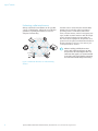
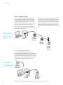
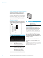
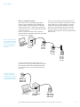
2 System Overview
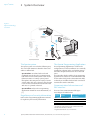
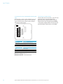
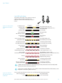
Figure 1.
Aperio technology
overview
Programming
Application
IEEE802.15.4
(2.4GHz)
Communication
Hub
RS-485,
Wiegand or
Ethernet
Offline
updater
USB
RFID
card
Aperio® OFFLINE
EAC system
(Electronic Access Control)
RFID
card
Aperio® ONLINE
The Aperio system
The Aperio system is used in the following way:
The user holds an RFID credential in front of an
online or offline lock.
∙∙ Aperio Online: An online lock sends card
credentials wirelessly to the communication
hub which in turn communicates with an EAC
(Electronic Access Control) system (wired
through RS-485, Wiegand or TCP/IP). The EAC
system makes the access decision. The decision
is sent via the communication hub to the lock
and access is granted or denied.
∙∙ Aperio Offline: Refer to the Programming
Application manual for more information, ref
[1].
Regulatory and security information
Refer to the Programming Application manual
for regulatory and security information.
The Aperio Programming Application
The Programming Application is used for the
configuration of a door installation. It is normally
installed on a laptop and is used with an Aperio
USB radio dongle connected to one of the USB
ports.
The USB radio dongle enables the programming
application to connect to a communication hub
and an online lock (via the communication hub)
or directly to an offline lock. V3 locks can also be
connected to with a USB cable.
Communication hub versions and
EAC interface
There are four communication hub types
according to the table below:
Version
Interface
AH15
AH20
AH30
AH40
Wiegand/RS 485*
Wiegand (Adv., Std)
RS-485
IP (Ethernet)
Maximum number of
locks/sensors
1
1
8
8/16**
* The firmware type loaded into the communication hub
controls what interface is enabled.
** Applicable for release 3.0.0 and onwards.
4
Aperio® Online Mechanical Installation Guide, Document No: ST-001323-D Date: 30 June 2015
Aperio®Online
3 Planning the Installation
It is very important to find the best possible
placement of the communication hub, in
order to get at stable and reliable radio link.
Depending on the floor plan of the installation
site, type of communication hubs used, use of
external antenna and presence of disturbances
will all affect the positioning of communication
hubs. Follow these guidelines to find the best
installation placement, also see following
sections for installation examples.
Placement options for
communication hub
General installation guidelines:
∙∙ Try to install so that locks and communication
hub ”see” each other with the LED on the
communication hub “pointing” towards the
lock.
∙∙ If this is not possible, find a placement so that
there are no concrete and metal objects in
between the lock and the communication hub.
∙∙ Avoid installing the communication hub in
a low position, where radio waves can be
blocked by objects or people passing by during
operation.
∙∙ When the internal antenna is used, the radio
coverage backwards is limited to 0.5 m/3 ft
for AH15 and 3 m/10 ft for AH20/30/40. The
coverage also depends on the type of wall it is
installed on.
∙∙ When the external antenna is used, the
radio coverage will be evenly distributed
perpendicular to the direction of the antenna
and in some directions the range may decrease.
However the maximum range will not increase.
See section "Radio coverage for external antenna"
on page 18 for details.
∙∙ The lock and the communication hub should
be placed on the same side of the door. Shorter
distance and “light” materials in the walls also
permits placement on opposite sides.
∙∙ Be aware of that nearby metallic sheet or mesh
will attenuate the radio signal. Inner ceiling,
for example, is sometimes covered with foil or
metallic mesh.
∙∙ Mirrors, heat insulating windows and larger
metallic objects (like cable ladders) have a
significant effect on radio signals and should
not be closer than 20 cm (8 inches) from lock
or Communication Hub.
∙∙ In difficult environments (for example where
heavy radio interference is expected), or
when the requirements on the radio link
quality are very high, it is recommended to
keep the distance between the lock and the
communication hub well below the maximum
recommended distance. There is no minimum
distance.
Aperio® Online Mechanical Installation Guide, Document No: ST-001323-D Date: 30 June 2015
5
Aperio® Online
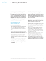
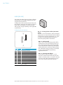
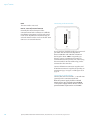
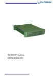
Evaluating radio interference
Always evaluate the installation site for possible
sources of disturbance. Follow these installation
guidelines regarding disturbances to ensure
adequate functionality:
1-3.5 m /
~ 3.5-12 ft
GSM/3G/
4G/LTE
∙∙ Possible sources of interference include WiFi/
WLAN routers and other radio transmitters
operating in the 2.4 GHz band, microwave
ovens, electric motors, wireless emergency exit
signs, mobile network antennas and other high
power electrical equipment. Depending on
the nature of the equipment, frequencies, and
power levels, keep the communication hub and
lock at a distance of at least 1-3.5 meters (3.5 12 feet) from these sources.
When installing in difficult environments with radio interference or with
the presence of metal objects that can
attenuate the signal, it is recommended
to test the radio signal before mounting
the communication hub permanently.
Figure 2. Minimum distance to radio emitting
devices
6
Aperio® Online Mechanical Installation Guide, Document No: ST-001323-D Date: 30 June 2015
Aperio®Online
4 Mechanical Installation
This chapter includes guidelines for selecting
the correct installation place for communication
hubs in an Aperio online EAC system.
This chapter also describes how to connect the
communication hubs to the power supply.
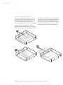
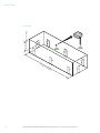
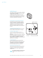
Mechanical installation AH15
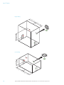
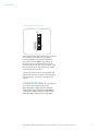
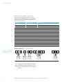
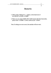
Minimum distance between AH15 communication hubs
If necessary, several communications hubs can
be positioned together with a minimum of 0.2
meter in between the hubs (or use one AH30
communication hub to pair with all three locks).
Figure 3. Minimum
X > 0.2 m / ~ 8 in
X
X
distance between
AH15 communication hubs with
E100 locks
Aperio® Online Mechanical Installation Guide, Document No: ST-001323-D Date: 30 June 2015
7
Aperio® Online
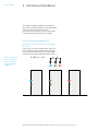
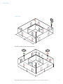
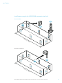
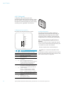
Placement options for AH15 when using E-cylinder locks
When using E-cylinder locks, the AH15 must be
The AH15 communication hub can be mounted
placed either in the roof, on the right or left wall
according to the following figure.
or on the opposite wall and within a 5 meters/16
feet range from the lock.
AH15 Communication hub installed on a wall,
with mounting holes according to marks.
It is important that the communication hub is
mounted with the mounting holes horizontally
aligned (in the ceiling, parallel to the direction of
the lock) and as close to the lock as possible.
AH15 Communication hub installed in the
ceiling (seen from above) with mounting hole
alignment.
The following pages show typical installations
based on field experience that will give a good
result for radio link quality. The colors indicate
which hubs and Aperio door locks that belong
together.
Door with Aperio e-cylinder lock
Figure 4. General
6 ft
<5
8
m
1
/~
Aperio® Online Mechanical Installation Guide, Document No: ST-001323-D Date: 30 June 2015
Parallel
< 4 m / ~ 13 ft
placement options
for AH15 with Ecylinder locks
Aperio®Online
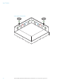
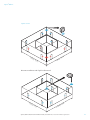
Installation examples for AH15 communication hub with E-cylinder locks
Short/long Corridors
<5
~
m/
16
ft
Alternate installation:
6 ft
<5
m
1
/~
Aperio® Online Mechanical Installation Guide, Document No: ST-001323-D Date: 30 June 2015
9
Aperio® Online
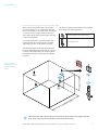
High ceiling
m/
~1
6 ft
<5
m/
~1
6 ft
< 4 m / ~ 13 ft
<5
1.5-4 m
~ 5-13 ft
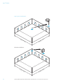
Low ceiling
<5
10
m/
~1
6 ft
<5
m/
~1
6 ft
Aperio® Online Mechanical Installation Guide, Document No: ST-001323-D Date: 30 June 2015
Aperio®Online
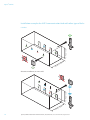
Square rooms
<5
m
/~
16
ft
<5
m
/~
16
ft
Alternate installation with ceiling placement:
<5
m
/~
16
<5
ft
<5
m
/~
16
ft
<5
m
/~
16
m
/~
16
ft
ft
Aperio® Online Mechanical Installation Guide, Document No: ST-001323-D Date: 30 June 2015
11
Aperio® Online
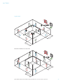
Open space environments
<5
m
/~
16
<5
ft
<5
12
m
/~
16
ft
<5
m
/~
16
m
/~
16
ft
ft
Aperio® Online Mechanical Installation Guide, Document No: ST-001323-D Date: 30 June 2015
Aperio®Online
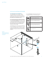
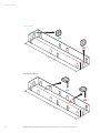
Placement options for AH15 when using other locks
When using non-cylinder locks, for example
The AH15 communication hub can be mounted
Escutcheon locks, it is recommended that the
according to the following figure.
AH15 is mounted on any of the walls, and within
a 5 meters/16 feet range from the lock in the
AH15 Communication hub installed on a wall,
zone shown in the figure. Placement in the roof
with mounting holes according to marks.
is not recommended.
It is important that the communication hub is
mounted with the mounting holes vertically
aligned and as close to the lock as possible.
Door with Aperio lock
The following pages show typical installations
based on field experience that will give a good
result for radio link quality. The colors indicate
which hubs and Aperio door locks that belong
together.
Figure 5. Place-
< 4 m / ~ 13 ft
ment options for
AH15 with other
locks
6 ft
<5
m
1
/~
Communication hubs should always be installed on the wall when using non e-cylinder
locks. Always align the mounting holes vertically when fastening.
Aperio® Online Mechanical Installation Guide, Document No: ST-001323-D Date: 30 June 2015
13
Aperio® Online
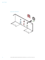
Installation examples for AH15 communication hub with other type of locks
< 4 m / ~ 13 ft
Corridors
6 ft
<5
m
1
/~
m
1
/~
< 4 m / ~ 13 ft
Alternate installation, on same wall:
6 ft
<5
14
Aperio® Online Mechanical Installation Guide, Document No: ST-001323-D Date: 30 June 2015
Aperio®Online
Square rooms
<5
<5
m/
~
m/
16
ft
~1
6 ft
Alternate installation on same wall:
<5
<5
m/
~
m/
16
ft
~1
6 ft
Aperio® Online Mechanical Installation Guide, Document No: ST-001323-D Date: 30 June 2015
15
Aperio® Online
Open space environments
>5
m/
~1
6 ft
>5
16
m/
~1
6 ft
Aperio® Online Mechanical Installation Guide, Document No: ST-001323-D Date: 30 June 2015
Aperio®Online
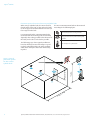
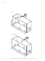
Mechanical installation AH20/30/40
Placement options for AH20/30/40
The AH20/30/40 communication hub is
designed so that it can establish a reliable
radio link regardless of the mounting position
(horizontal or vertical) of the communication
hub and the type of lock being used.
It is recommended that the distance between
the lock and the communication hub is limited
to 15-25 meters/50-80 feet, depending on the
environment. However, under good conditions
(free air between the units and limited radio
interference from other transmitters) the
distance can be extended.
The following pages shows typical installations
based on field experience that will give a good
result for radio link quality. The colors indicate
which hubs and Aperio door locks that belong
together.
The AH20/30/40 communication hub can be
mounted according to the following figure.
AH20/30/40 Communication hub with
internal antenna, installed on a wall.
AH20/30/40 Communication hub with
internal antenna, installed in the ceiling.
AH20/30/40 Communication hub with
external antenna, installed in the ceiling.
Door with Aperio lock
Figure 6.
Placement options for
AH20/30/40 communication hub
.2
<0
Aperio® Online Mechanical Installation Guide, Document No: ST-001323-D Date: 30 June 2015
~
m/
8 in
17
Aperio® Online
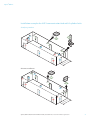
Radio coverage for external antenna
The general guideline for using an external
antenna is to obtain radio coverage in a even
globe around the external antenna. Note that
the external antenna does not extend the
maximum range, which is still 15-25 m/50-80 ft.
An example of a situation where external
antenna could be used is when the placement
options are limited for the communication hub.
<2
5m
<2
/~
80
5m
18
The following figure illustrates the difference in
radio pattern for external and internal antenna.
(Note that this is only an simplified picture of
the radio reception for each antenna, showing
the theoretical characteristics. The real radio
coverage also vary for each installation site.)
ft
/~
80
ft
<2
5m
/~
80
ft
Aperio® Online Mechanical Installation Guide, Document No: ST-001323-D Date: 30 June 2015
Aperio®Online
Installation examples for AH20/30/40 communication hub
Short Corridors
<2
5m
/~
80
ft
80
ft
Alternate installation:
<2
5m
/~
Aperio® Online Mechanical Installation Guide, Document No: ST-001323-D Date: 30 June 2015
19
Aperio® Online
Long corridors
<5
0m
/~
16
0 ft
Alternate installation:
<5
0m
20
/~
16
0 ft
Aperio® Online Mechanical Installation Guide, Document No: ST-001323-D Date: 30 June 2015
Aperio®Online
< 5 m / ~ 16 ft
High ceiling
<2
5m
/~
80
ft
80
ft
5 -20 m / ~ 16-65 ft
Alternate installation:
<2
5m
/~
Aperio® Online Mechanical Installation Guide, Document No: ST-001323-D Date: 30 June 2015
21
Aperio® Online
< 1.5 - 5 m / ~ 5 - 16 ft
Low ceiling
<2
5m
22
/~
80
ft
Aperio® Online Mechanical Installation Guide, Document No: ST-001323-D Date: 30 June 2015
Aperio®Online
Square rooms
<2
0m
/~
65
ft
0
<2
~
m/
65
ft
Alternate installation with “light” wall material:
<2
0m
/~
65
ft
0
<2
~
m/
65
ft
Aperio® Online Mechanical Installation Guide, Document No: ST-001323-D Date: 30 June 2015
23
Aperio® Online
Open space environments
<2
0m
/~
65
ft
0
<2
ft
65
~
m/
Alternate installation:
<
24
20
m/
~6
5 ft
<
20
~
m/
65
ft
Aperio® Online Mechanical Installation Guide, Document No: ST-001323-D Date: 30 June 2015
Aperio®Online
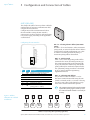
5 Configuration and Connection of Cables
AH15 (RS-485)
This chapter describes how to perform a default
configuration of an AH15 communication hub
using the RS-485 interface.
Configuration of the communication hub to
the EAC includes setting the DIP switches,
connecting it to the RS-485 bus and connecting
it to power supply, according to the applicable
section below.
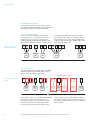
Configuring the DIP switches
DIP 1-5 – Selecting the EAC address/Automatic
paring
The DIP 1-5 has two functions, either automatic
paring mode, or manual selection of EAC address
on the RS485. Default configuration is to select
an address according to below. By doing so
automatic pairing will be deactivated.
8-24V
GND
GREEN
RED
DATA0
Figure 7. Address
allocation in a default
installation
ON
1 2 3 4 5 6 7 8
DIP
∙∙ DIP 1-5 – Pairing mode
DATA1
RS485 B
RS485 A
Abbr.
Description
8
7
6
5
4
3
2
TERM
UP
DOWN
A4
A3
A2
A1
1
A0
Activates termination of EAC bus
Activation of pull up resistor
Activation of pull down resistor
Manual EAC Address
Manual EAC Address
Manual EAC Address
Manual EAC Address
Manual EAC Address/Automatic
pairing (DIP 1-5 = OFF)
Lock
0x01
Lock
0x02
Lock
0x03
AH15
0x01
AH15
0x02
AH15
0x03
...
If DIP 1-5 are set to OFF, pairing mode will be
activated. This means that after powering on
the communication hub it will automatically
try to pair with locks within range. Automatic
pairing will only be made with unpaired locks.
The automatic pairing procedure is described
in ref [2], Aperio Online Programming
Application manual.
∙∙ DIP 1-5 – Selecting EAC address
It is possible to select an address 1-31 for
the AH15 communication hub using the DIP
switch. For mixed modes, see section "Selecting
the correct EAC address (AH15/AH30)" on page
42 for more details and advance options.
The communication hub must be power
cycled after changing the address, since
the state of the DIP switch is read only at
startup.
Lock
0x11
Lock
0x12
AH15
0x11
AH15
0x12
Lock
0x21
...
AH15
0x21
Lock
0x2F
...
AH15
0x2F
Address 1-31 (-63 using the Programming application)
Aperio® Online Mechanical Installation Guide, Document No: ST-001323-D Date: 30 June 2015
25
Aperio® Online
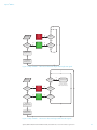
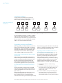
DIP 6-8 – RS-485 bus settings
DIP switch 6 and 7 activate pull up and pull
down-resistors, which must be enabled once
per bus. Either in the EAC system (see the EAC
documentation for the EAC in use, for use of
pull up or pull down on the EAC side), or on one
communication hub on the RS-485-bus.
DIP 8 is used to terminate the bus, which is
activated for communication hubs connected in
end position on the bus.
Figure 8. Daisy chain
connected communication hubs, set DIP 6
and 7 in ON position
for one communication hub
If there is more than one communication hub
to connect they should be connected in a daisy
chain. In this case, set DIP switches 6-8 in OFF
position for all communication hubs, except for
the communication hub at the end of the bus
which must have DIP switch 8 in ON position.
The RS-485 bus must be terminated on the EAC
side.
A
B
EAC system
A
B
Hub 1
DIP 6 OFF
DIP 7 OFF
DIP 8 OFF
Termination
enabled
A
B
Hub 2
DIP 6 OFF
DIP 7 OFF
DIP 8 OFF
A
B
Hub N
End of Bus
DIP 6 ON
DIP 7 ON
DIP 8 ON
For a star connection, which is not
recommended and should only be used in
exceptional cases, set DIP 6 and 7 in ON position
for one communication hub. DIP 8 must be in
ON position for all communication hubs. The RS485 bus must be terminated on the EAC side as
well as on the end hub on each branch.
Figure 9. Star con-
nected communication hubs, DIP 6 and 7
in ON position for one
communication hub
A
B
Hub 1
DIP 6 ON
DIP 7 ON
DIP 8 ON
A
B
EAC system
26
Termination
enabled
A
B
Hub 2
DIP 6 OFF
DIP 7 OFF
DIP 8 ON
Aperio® Online Mechanical Installation Guide, Document No: ST-001323-D Date: 30 June 2015
Aperio®Online
Connecting to the RS-485 bus
8-24V
GND
GREEN
RED
DATA0
ON
1 2 3 4 5 6 7 8
DATA1
RS485 B
RS485 A
The RS-485 bus should be made up of a twistedpair cable with characteristic impedance
between 90 Ohm and 120 Ohm. Maximum
bus length is about 1000 m. Depending on
the EAC system, a maximum of 32 units (31
communication hubs plus the EAC, when using
the DIP Switch for RS-485-addressing) can be
connected to the same bus.
Connect all RS485 A connectors together and
all RS485 B connectors together, depending on
connection type, see Figure 8 and Figure 9 on
page 26.
Connecting to supply voltage
Connect the wires to 8-24 VDC, 0.9 W and GND
(ground) on the communication hub.
Note! The power supply shall be a Limited
Power Source (LPS) according to EN 609501. The power supply shall be 3 A over current
protected. Wire requirements 16-22 AWG.
Aperio® Online Mechanical Installation Guide, Document No: ST-001323-D Date: 30 June 2015
27
Aperio® Online
AH15 (Wiegand)
Configuring and connecting the AH15
communication hub to the EAC includes setting
the DIP switches, connecting it to the Wiegand
interface bus and connecting it to power supply,
according to the applicable section below.
Configuring the DIP switches
Details for the Wiegand interface signals:
8-24V
GND
Default configuration
According to the figure, all DIP switches in
position OFF on the communication hub give
a default Wiegand configuration that will fit
most EAC systems. However, customizing the
configuration can result in better performance.
GREEN
RED
DATA0
ON
1 2 3 4 5 6 7 8
DATA1
RS485 B
RS485 A
DIP 1 - Selecting LED input signals and access
decision
If the EAC system can send a signal that actively
asserts an access denied decision (Red LED), DIP
1 should be set to ON. This will give:
∙∙ Shorter response time at a denied access.
DIP Abbr.
8
7
6
TERM
Not applicable for Wiegand. Set to OFF.
UP
Not applicable for Wiegand. Set to OFF.
DOWN Not applicable for Wiegand. Set to OFF.
∙∙ Possibility to use override credentials in the
lock.
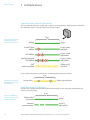
The flowcharts below explain how the LED input
signals are used to derive an access decision. The
OFF and ON variants are depicted.
ON = Starts in pairing mode.
OFF = Normal use.
Controls byte order of transmitted
credentials.
OFF => The byte order is left as is.
ON => The byte order is reversed compared
to what is received as input to the Hub
Wiegand EAC interface component.
Controls addition of parity bits on
transmitted credentials. One even parity
bit before and one odd parity bit after the
actual credentials.
OFF => Addition of parity is disabled.
Credentials are transmitted as received.
ON => Addition of parity bits is enabled.
5
A4
4
A3
3
A2
2
A1
Reserved for future use. Set to OFF.
A0
Controls use of Red LED signal for access
decision.
ON = Red LED is used.
OFF = Red LED is ignored.
1
28
Description
Aperio® Online Mechanical Installation Guide, Document No: ST-001323-D Date: 30 June 2015
Aperio®Online
Signal
access
denied
to lock
Data from
RFID reader
Yes
Timer
expired?
No
Green LED
active?
Yes
Signal
access
granted
to lock
Yes
No
Green LED
active?
No
Transmit via
Wiegand interface
On completion
start timer (1.5 s)
Figure 10. Dip Switch 1 – OFF: Access decision logic with single LED signal
Timer
expired?
Data from
RFID reader
No
Red LED
active?
Yes
Signal
access
denied
to lock
Yes
No
Green LED
active?
No
Yes
Exit without access
decision to lock*
* This means that
override credentials
will be used in the lock.
Red LED
active?
No
Yes
Signal
access
granted
to lock
Yes
Green LED
active?
No
Transmit via
Wiegand interface
On completion
start timer (1.5 s)
Figure 11. Dip Switch 1 – ON: Access decision logic with two LED signals
Aperio® Online Mechanical Installation Guide, Document No: ST-001323-D Date: 30 June 2015
29
Aperio® Online
If the EAC system is using output signal Red LED for other purposes than to control the lock,
then this signal should not be connected to the communication hub. Set DIP switch 1 in
position OFF in this case
If the EAC system is using output signal Green LED for other purposes than to control the
lock, then this signal should not be connected to the communication hub. Use a lock relay
output or another similar lock control output from the EAC system instead.
Use of override credential is not possible combined if DIP switch 1 in position OFF. The reason is that the Hub produces an “access denied” decision based on time out in this case.
DIP 2 (Future use)
Note! This DIP must always be set to OFF.
DIP 3 - Parity bit
Note! Transmitted credentials may include parity
anyway, although addition of parity is disabled in
the Hub Wiegand EAC interface component.
The reason is that parity bits are usually already
included on the credential.
DIP 4 - Byte Order
Note! This setting is ignored if the credential
length does not make up complete bytes.
Note! The byte order received as input to the
Hub Wiegand EAC interface component in
the case of a 32 bit MIFARE UID credential is
UID[3], UID[2], UID[1], UID[0]. This means that
the byte order is already reversed earlier in the
chain compared to the order specified in RFID
interface standard ISO 14443-3.
DIP 5 - Pairing mode
If DIP switch 5 is set to ON, pairing mode will be
activated. This means that after powering on the
communication hub it will automatically try to
pair with locks within reach. Automatic pairing
will only be made with unpaired locks. See ref [2]
Aperio Online Programming Application manual
for instructions on how to perform the pairing.
30
Aperio® Online Mechanical Installation Guide, Document No: ST-001323-D Date: 30 June 2015
Aperio®Online
Connecting to the Wiegand bus
The AH15 communication hub has four Wiegand
signals plus ground. Purpose and connection of
these signals are described in the table below.
8-24V
GND
GREEN
RED
DATA0
ON
1 2 3 4 5 6 7 8
Hub connector
designation
8-24V
GND
DATA1
RS485 B
RS485 A
Description
Connect to…
Positive voltage
Ground
EAC power supply.
EAC system ground.
Wiegand Green LED output on EAC system.
Alternatively, connect to a lock control relay output
on EAC system.
Wiegand Red LED output on EAC system.
Alternatively, leave unconnected if signal is selected
not to be used by DIP switch 1.
GREEN
Wiegand Green LED signal. Input to
communication hub. Used for access decision.
RED
Wiegand Red LED signal. Input to communication
hub. Used for access decision.
DATA0
DATA1
RS485 B
RS485 A
Wiegand Data 0 signal. Output from
communication hub. Used to transmit credentials.
Wiegand Data 1 signal. Output from
communication hub. Used to transmit credentials.
NOT APPLICABLE
NOT APPLICABLE
Wiegand Data 0 on EAC system.
Wiegand Data 1 on EAC system.
-
Connecting to supply voltage
Connect the wires to 8-24 VDC, 0.9 W and GND
(ground) on the communication hub.
Note! The power supply shall be a Limited
Power Source (LPS) according to EN 609501. The power supply shall be 3 A over current
protected. Wire requirements 16-22 AWG.
Aperio® Online Mechanical Installation Guide, Document No: ST-001323-D Date: 30 June 2015
31
Aperio® Online
AH20 (Standard and Advanced Wiegand)
AH20 communication hub is available in two
versions, Standard and Advanced Wiegand. The
Advanced version is equipped with relays.
Configuring and connecting the communication
hub to the EAC includes setting the DIP switches,
connecting it to the Wiegand interface bus and
connecting it to power supply, according to the
applicable section below.
Configuring the DIP switch
Details for the Wiegand interface signals (Relays
are only available for AH20 Advanced Wiegand):
DIP Abbr.
Description
1
Controls use of Red LED signal for access
decision.
ON = Red LED is used.
OFF = Red LED is ignored.
A0
K500
NCL1
COM1
K502
A
NCL2
B
COM2
D1
NOP2
D0
NCL3
RED
COM3
GREEN
NOP3
GND
S101
8-24V
K503
NCL4
COM4
ON
K501
NOP1
1 2 3 4 5 6 7 8 9 10
S100
J100
NOP4
J103
DIP Abbr.
10
9
32
Description
INT/EXT Internal/external antenna
Not used
8
TERM
Not applicable for Wiegand. Set to OFF.
7
UP
Not applicable for Wiegand. Set to OFF.
6
DOWN
Not applicable for Wiegand. Set to OFF.
5
A4
4
A3
3
A2
2
A1
ON = Starts in pairing mode.
OFF = Normal use.
Controls byte order of transmitted
credentials.
OFF => The byte order is left as is.
ON => The byte order is reversed
compared to what is received as input
to the Hub Wiegand EAC interface
component.
Controls addition of parity bits on
transmitted credentials. One even parity
bit before and one odd parity bit after the
actual credentials.
OFF => Addition of parity is disabled.
Credentials are transmitted as received.
ON => Addition of parity bits is enabled.
Default configuration
According to the figure, DIP switches 1-9 in
position OFF and DIP switch 10 in ON (Internal
antenna) on the communication hub will give
a default Wiegand configuration that will fit
most EAC systems. However, customizing the
configuration can result in better performance.
DIP 1 - Selecting LED input signals and access
decision
If the EAC system can send a signal that actively
asserts an access denied decision (Red LED), DIP
1 should be set to ON.
This will give:
∙∙ Shorter response time at a denied access.
∙∙ Possibility to use override credentials in the
lock.
The flowcharts below explain how the LED input
signals are used to derive an access decision. The
OFF and ON variants are depicted.
Set to OFF. Reserved for future use.
Aperio® Online Mechanical Installation Guide, Document No: ST-001323-D Date: 30 June 2015
Aperio®Online
Signal
access
denied
to lock
Data from
RFID reader
Yes
Timer
expired?
No
Green LED
active?
Yes
Signal
access
granted
to lock
Yes
No
Green LED
active?
No
Transmit via
Wiegand interface
On completion
start timer (1.5 s)
Figure 12. Dip Switch 1 – OFF: Access decision logic with single LED signal
Timer
expired?
Data from
RFID reader
No
Red LED
active?
Yes
Signal
access
denied
to lock
Yes
No
Green LED
active?
No
Yes
Exit without access
decision to lock*
* This means that
override credentials
will be used in the lock.
Red LED
active?
No
Yes
Signal
access
granted
to lock
Yes
Green LED
active?
No
Transmit via
Wiegand interface
On completion
start timer (1.5 s)
Figure 13. Dip Switch 1 – ON: Access decision logic with two LED signals
Aperio® Online Mechanical Installation Guide, Document No: ST-001323-D Date: 30 June 2015
33
Aperio® Online
The communication hub must be power cycled after any changes on the DIP switch, since
the state of the DIP switch is read only at startup. If the EAC system is using output signal Red
LED for other purposes than to control the lock, then this signal should not be connected to
the communication hub. Set DIP switch 1 in position OFF in this case.
If the EAC system is using output signal Green LED for other purposes than to control the
lock, then this signal should not be connected to the communication hub. Use a lock relay
output or another similar lock control output from the EAC system instead.
Use of override credential is not possible if DIP switch 1 is in position OFF. The reason is that
the communication hub produces an “access denied” decision based on time out in this
case.
DIP 2 (Future use)
Note! This DIP must always be set to OFF.
DIP 3 - Parity bit
Note! Transmitted credentials may include parity
anyway, although addition of parity is disabled in
the Hub Wiegand EAC interface component.
The reason is that parity bits are usually already
included on the credential.
DIP 4 - Byte Order
Note! This setting is ignored if the credential
length does not make up complete bytes.
Note! The byte order received as input to the
Hub Wiegand EAC interface component in
the case of a 32 bit MIFARE UID credential is
UID[3], UID[2], UID[1], UID[0]. This means that
the byte order is already reversed earlier in the
chain compared to the order specified in RFID
interface standard ISO 14443-3.
DIP 5 - Pairing mode
If DIP switch 5 is set to ON, pairing mode will be
activated. This means that after powering the
communication hub it will automatically try to
pair with locks within reach. Automatic pairing
will only be made with unpaired locks. See ref [2]
Aperio Online Programming Application manual
for instructions on how to perform the pairing.
34
Aperio® Online Mechanical Installation Guide, Document No: ST-001323-D Date: 30 June 2015
Aperio®Online
Connecting to the Wiegand bus
The AH20 communication hub has four Wiegand
signals plus ground. Purpose and connection of
these signals are described in the table below.
K500
NCL1
COM1
K502
A
NCL2
B
COM2
D1
NOP2
D0
NCL3
RED
COM3
GREEN
NOP3
GND
S101
8-24V
K503
NCL4
COM4
ON
K501
NOP1
1 2 3 4 5 6 7 8 9 10
S100
J100
NOP4
J103
Hub connector
designation
A
B
DATA1
DATA0
Description
Connect to…
NOT APPLICABLE
NOT APPLICABLE
Wiegand Data 1 signal. Output from
communication hub. Used to transmit credentials.
Wiegand Data 0 signal. Output from
communication hub. Used to transmit credentials.
-
RED
Wiegand Red LED signal. Input to communication
hub. Used for access decision.
GREEN
Wiegand Green LED signal. Input to
communication hub. Used for access decision.
GND
8-24V
Ground
Positive voltage
Wiegand Data 1 on EAC system.
Wiegand Data 0 on EAC system.
Wiegand Red LED output on EAC system.
Alternatively, leave unconnected if signal is selected
not to be used by DIP switch 1.
Wiegand Green LED output on EAC system.
Alternatively, connect to a lock control relay output
on EAC system.
EAC system ground.
EAC power supply.
Aperio® Online Mechanical Installation Guide, Document No: ST-001323-D Date: 30 June 2015
35
Aperio® Online
Connecting the relays (AH20 Advanced Wiegand
only)
The four form C relays on the AH20 version can
be used by the EAC to supervise door position
status, handle position, battery alarm output,
and tamper alarm output.
Connecting to supply voltage
Connect the wires to 8-24 VDC, 2 W and GND
(ground) on the communication hub.
Note! The power supply shall be a Limited
Power Source (LPS) according to EN 609501. The power supply shall be 3 A over current
protected. Wire requirements 16-22 AWG.
K500
NCL1
COM1
K502
A
NCL2
B
COM2
D1
NOP2
D0
NCL3
RED
COM3
GREEN
NOP3
GND
S101
8-24V
K503
NCL4
COM4
ON
K501
NOP1
1 2 3 4 5 6 7 8 9 10
S100
J100
NOP4
J103
Relays
Relay 1/K500
Relay 2/K501
Relay 3/K502
Description
DPS (Door Position Sensor)
RX (Request to exit)
Battery Alarm Output
Relay 4/K503
Tamper Alarm Output/Lock Jammed
Relay Contacts
NCL
COM
NOP
Description
Normal Closed
Common
Normal Open
Relay max voltage: 30 VDC
Relay max current: 1 A resistive load
36
Aperio® Online Mechanical Installation Guide, Document No: ST-001323-D Date: 30 June 2015
Aperio®Online
AH30 (RS-485)
This chapter describes how to perform a default
configuration of an AH30 communication hub
using the RS-485 interface.
Configuration of the communication hub to the
EAC includes setting the DIP switches and, if not
done earlier, connecting it to the RS-485 bus
and to power supply, according to the applicable
section below.
A
B
D0
ON
D1
RED
GREEN
1 2 3 4 5 6 7 8 9 10
Configuring the DIP switches
S101
GND
8-24V
J100
DIP
Abbr.
Description
10
INT/EXT
Internal/external antenna
9
Not used
8
TERM
Activates termination of EAC bus
7
UP
Activation of pull up resistor
6
DOWN
Activation of pull down resistor
5
A4
Manual EAC Address
4
A3
Manual EAC Address
3
A2
Manual EAC Address
2
A1
Manual EAC Address
A0
Manual EAC Address/Automatic pairing
(DIP 1-5 = OFF)
1
DIP 1-5 – Selecting the EAC address/Automatic
paring
The DIP 1-5 has two functions, either automatic
paring mode, or manual selection of EAC address
on the RS485. Default configuration is to select
an address according to below. By doing so
automatic pairing will be deactivated.
∙∙ DIP 1-5 – Pairing mode
If DIP 1-5 are set to OFF, pairing mode will be
activated. This means that after powering on
the communication hub it will automatically
try to pair with locks within range. Automatic
pairing will only be made with unpaired locks.
The automatic pairing procedure is described
in ref [2], Aperio Online Programming
Application manual.
∙∙ DIP 1-5 – Selecting EAC address
It is possible to select an address 1-31 for
the AH15 communication hub using the DIP
switch. For mixed modes, see section "Selecting
the correct EAC address (AH15/AH30)" on page
42 for more details and advance options.
Aperio® Online Mechanical Installation Guide, Document No: ST-001323-D Date: 30 June 2015
37
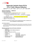
Aperio® Online
Select a unique EAC address 1-15 for each
communication hub by use of the DIP switch
according to the table below. (The resulting lock
addresses for each communication hub address
are shown to the right):
DIP 4 – DIP 1
AH30 Hub address
Lock addresses
0x01
0x01, 0x11, 0x21, 0x31, 0x41, 0x51, 0x61, 0x71
0000
Reserved
0001
Figure 14. Address al-
location in a default
installation
0010
0x02
0x02, 0x12, 0x22, 0x32, 0x42, 0x52, 0x62, 0x72
0011
0x03
0x03, 0x13, 0x23, 0x33, 0x43, 0x53, 0x63, 0x73
0100
0x04
0x04, 0x14, 0x24, 0x34, 0x44, 0x54, 0x64, 0x74
0101
0x05
0x05, 0x15, 0x25, 0x35, 0x45, 0x55, 0x65, 0x75
0110
0x06
0x06, 0x16, 0x26, 0x36, 0x46, 0x56, 0x66, 0x76
0111
0x07
0x07, 0x17, 0x27, 0x37, 0x47, 0x57, 0x67, 0x77
1000
0x08
0x08, 0x18, 0x28, 0x38, 0x48, 0x58, 0x68, 0x78
1001
0x09
0x09, 0x19, 0x29, 0x39, 0x49, 0x59, 0x69, 0x79
1010
0x0A
0x0A, 0x1A, 0x2A, 0x3A, 0x4A, 0x5A, 0x6A, 0x7A
1011
0x0B
0x0B, 0x1B, 0x2B, 0x3B, 0x4B, 0x5B, 0x6B, 0x7B
1100
0x0C
0x0C, 0x1C, 0x2C, 0x3C, 0x4C, 0x5C, 0x6C, 0x7C
1101
0x0D
0x0D, 0x1D, 0x2D, 0x3D, 0x4D, 0x5D, 0x6D, 0x7D
1110
0x0E
0x0E, 0x1E, 0x2E, 0x3E, 0x4E, 0x5E, 0x6E, 0x7E
1111
0x0F
0x0F, 0x1F, 0x2F, 0x3F, 0x4F, 0x5F, 0x6F, 0x7F
The following figure shows an example of a
default installation.
Lock Lock Lock
0x01 0x11 0x21
Lock
0x02
Lock Lock
0x03 0x13
Lock Lock Lock Lock Lock
0x04 0x14 0x24 0x34 0x44
AH30
0x01
AH30
0x02
AH30
0x03
AH30
0x04
Lock Lock Lock
0x0F 0x1F 0x2F
...
Address 1-15
The communication hub must be power
cycled after changing the address, since
the state of the DIP switch is read only at
startup.
38
Aperio® Online Mechanical Installation Guide, Document No: ST-001323-D Date: 30 June 2015
AH30
0x0F
Aperio®Online
DIP 6-8 – RS-485 bus settings
DIP switch 6 and 7 activate pull up and pull
down-resistors, which must be enabled once
per bus. Either in the EAC system (see the EAC
documentation for use of pull up or pull down
on the EAC side), or on one communication hub
on the RS-485-bus.
DIP 8 is used to terminate the bus, which is
activated for the communication hub connected
in end position on the bus.
Figure 15. Daisy chain
connected communication hubs, set DIP 6
and 7 in ON position
for one communication hub
If there is more than one communication hub
to connect they should be connected in a daisy
chain. In this case, set DIP switches 6-8 in OFF
position for all communication hubs, except
for the communication hub at the end of the
bus which must have DIP switches 6-8 in ON
position. The RS-485 bus must be terminated on
the EAC side.
A
B
EAC system
A
B
Hub 1
DIP 6 OFF
DIP 7 OFF
DIP 8 OFF
Termination
enabled
A
B
Hub 2
DIP 6 OFF
DIP 7 OFF
DIP 8 OFF
A
B
Hub N
End of Bus
DIP 6 ON
DIP 7 ON
DIP 8 ON
For a star connection, set DIP 6 and 7 in ON
position for one communication hub. DIP 8 must
be in ON position for all communication hubs.
The RS-485 bus can not be terminated on the
EAC side.
Figure 16. Star con-
nected communication hubs, DIP 6 and 7
in ON position for one
communication hub
A
B
Hub 1
DIP 6 ON
DIP 7 ON
DIP 8 ON
A
B
EAC system
Termination
enabled
A
B
Hub 2
DIP 6 OFF
DIP 7 OFF
DIP 8 ON
Aperio® Online Mechanical Installation Guide, Document No: ST-001323-D Date: 30 June 2015
39
Aperio® Online
A
B
D1
D0
ON
DIP 10 – Internal/external antenna
Normally the internal antenna of the
communication hub is sufficient. In a difficult
installation environment or if the radio signal
needs to be amplified for extended range, an
external antenna can be used. Set the DIP 10 to
OFF to use an external antenna.
Connecting to the RS-485 bus
1 2 3 4 5 6 7 8 9 10
DIP 9
This DIP switch is not used.
RED
GREEN
GND
8-24V
The RS-485 bus should be made up of a twistedpair cable with characteristic impedance
between 90 Ohm and 120 Ohm. Maximum
bus length is about 1000 m. Depending on
the EAC system, a maximum of 32 units (31
communication hubs plus the EAC, when using
the DIP Switch for RS-485-addressing) can be
connected to the same bus.
Connect all RS485 A connectors together and
all RS485 B connectors together, depending on
connection type, see Figure 15 and Figure 16 on
page 39.
Connecting to supply voltage
Connect the wires to 8-24 VDC, 1.1 W and GND
(ground) on the communication hub.
Note! The power supply shall be a Limited
Power Source (LPS) according to EN 609501. The power supply shall be 3A over current
protected. Wire requirements 16-22 AWG.
40
Aperio® Online Mechanical Installation Guide, Document No: ST-001323-D Date: 30 June 2015
Aperio®Online
AH40 (Ethernet)
This chapter describes how to perform a default
configuration of an AH40 communication hub
using the Ethernet interface.
Configuration of the communication hub to
the EAC includes setting jumpers, connecting it
to Ethernet and connecting it to power supply,
according to applicable section below.
Setting jumper for internal/external antenna
Normally the communication hub’s internal
antenna is sufficient. In a difficult installation
environment or if the radio signal needs to be
amplified in a certain direction, an external
antenna can be used. Connect the two left
pins ("EXT") with the jumper to use an external
antenna.
Setting jumper for pariing mode
To activate automatic pairing, connect the two
left pins ("PAIR") with the jumper, see figure.
Connect to supply voltage
Connect the power and ground to the “+”
and the “-“ terminals of the connector marked
“8V-24V”.
Note! Power supply input, 8-24 VDC, 3.5 W. The
power supply shall be a Limited Power Source
(LPS) according to EN 60950-1. The power
supply shall be 3 A over current protected. Wire
requirements 16-22 AWG.
Jumper for antenna
ANTENNA
LINK
EXT INT
PAIR
- +
8-24V
Ethernet
Jumper for pairing mode
Connecting Ethernet
Connect an Ethernet cable to the Hub and
make sure that the Ethernet “LINK” LED is green,
which indicates that the Ethernet link level is
established. The Hub supports 10/100 Mbit/s
half and full duplex with auto-negotiation.
Using Power over Ethernet (PoE)
The communication Hub can also be powered
using Power over Ethernet by connecting it to
an Ethernet switch or other equipment that
supports this.
Due to EMC regulations, do not connect
any other power supply when PoE is
used.
Aperio® Online Mechanical Installation Guide, Document No: ST-001323-D Date: 30 June 2015
41
Aperio® Online
6 Appendix
Selecting the correct EAC address (AH15/AH30)
Selecting EAC addresses for communication
hubs and locks correctly during installation is
important in order not to cause address conflicts
in your installation.
∙∙ Address 16-31: For AH30/AH15
The communication hubs can use different
address ranges depending on the installation:
∙∙ Address 32-63: For AH30/AH15
∙∙ Address 1-15: For AH30 communication hubs
with one or several locks paired and AH15
communication hubs. Address is selected by
DIP Switch or the Programming Application.
communication hubs in single device mode
(only one lock paired). Address is selected by
DIP Switch or the Programming Application.
communication hubs in single device mode
(only one lock paired). Address is selected only
by the Programming Application.
The final lock EAC address depends on the
communication hub address. For AH15
communication hubs the lock address is equal to
the hub address. For AH30 communication hubs
the lock address is decided by the addressing
table.
Addressing table – normal address offset
An AH30 communication hub can pair with
up to 8 locks. When pairing several locks to a
communication hub, the following addresses
are used for the address range 1-15. Above this
range only one lock can be paired.
DIP 4 – DIP 1
0000
0001
0010
0011
0100
0101
0110
0111
1000
1001
1010
1011
1100
1101
1110
1111
AH30 Hub address Lock addresses
Reserved
0x01
0x01, 0x11, 0x21, 0x31, 0x41, 0x51, 0x61, 0x71
0x02
0x02, 0x12, 0x22, 0x32, 0x42, 0x52, 0x62, 0x72
0x03
0x03, 0x13, 0x23, 0x33, 0x43, 0x53, 0x63, 0x73
0x04
0x04, 0x14, 0x24, 0x34, 0x44, 0x54, 0x64, 0x74
0x05
0x05, 0x15, 0x25, 0x35, 0x45, 0x55, 0x65, 0x75
0x06
0x06, 0x16, 0x26, 0x36, 0x46, 0x56, 0x66, 0x76
0x07
0x07, 0x17, 0x27, 0x37, 0x47, 0x57, 0x67, 0x77
0x08
0x08, 0x18, 0x28, 0x38, 0x48, 0x58, 0x68, 0x78
0x09
0x09, 0x19, 0x29, 0x39, 0x49, 0x59, 0x69, 0x79
0x0A
0x0A, 0x1A, 0x2A, 0x3A, 0x4A, 0x5A, 0x6A, 0x7A
0x0B
0x0B, 0x1B, 0x2B, 0x3B, 0x4B, 0x5B, 0x6B, 0x7B
0x0C
0x0C, 0x1C, 0x2C, 0x3C, 0x4C, 0x5C, 0x6C, 0x7C
0x0D
0x0D, 0x1D, 0x2D, 0x3D, 0x4D, 0x5D, 0x6D, 0x7D
0x0E
0x0E, 0x1E, 0x2E, 0x3E, 0x4E, 0x5E, 0x6E, 0x7E
0x0F
0x0F, 0x1F, 0x2F, 0x3F, 0x4F, 0x5F, 0x6F, 0x7F
When configuring installations that differ from
the default configuration described in section
DIP 1-5 – Selecting the EAC address/Automatic
paring on page 38, use this table to keep track
42
of what addresses are used by the locks/sensors
in your installation in order to avoid addressing
conflicts according to section "Installation
examples" on page 44 for mixed installations.
Aperio® Online Mechanical Installation Guide, Document No: ST-001323-D Date: 30 June 2015
Aperio®Online
Addressing table – legacy address offset
Legacy addressing mode is an alternative
addressing mode that can be set by the
Programming Application in the configuration
wizard. The lock addresses in this mode are set
consecutively. For example, if communication
hub has address 1, the locks will get address 1-8,
9-16, 17-24 etc.
DIP 5 – DIP 1
0000
0001
0010
0011
0100
...
AH30 Hub address Lock addresses
Reserved
0x01
0x01, 0x02, 0x03, 0x04, 0x05, 0x06, 0x07, 0x08
0x02
0x09, 0x0A, 0x0B, 0x0C, 0x0D, 0x0E, 0x0F, 0x10
0x03
0x11, 0x12, 0x13, 0x14, 0x14, 0x16, 0x17, 0x18
0x04
0x19, 0x1A, 0x1B, 0x1C, 0x1D, 0x1E, 0x1F, 0x20
This mode is used for older EAC systems that
cannot handle high EAC addresses where the
limit for example is 32 or 64.
Aperio® Online Mechanical Installation Guide, Document No: ST-001323-D Date: 30 June 2015
43
Aperio® Online
Installation examples
See below for examples of the most common
installations and how the addressing is made and
how possible address conflicts are avoided.
One-to-several installation
This is the default installation as described
in section "DIP 1-5 – Selecting the EAC address/
Automatic paring" on page 37, with up to 15
AH30 communication hubs paired with one or
several locks. Only the addresses 1-15 are used.
Figure 17. One-to
several installation
The addressing table above does not need to
be consulted in this type of installation, since all
the lock addresses used are unique. Addressing
is simply made by selecting a unique address for
each communication hub.
Lock Lock Lock
0x01 0x11 0x21
Lock
0x02
Lock Lock
0x03 0x13
Lock Lock Lock Lock Lock
0x04 0x14 0x24 0x34 0x44
AH30
0x01
AH30
0x02
AH30
0x03
AH30
0x04
Lock Lock Lock
0x0F 0x1F 0x2F
AH30
0x0F
...
Address 1-15
Mixed installation
A mixed installation uses both AH15 and AH30
communication hubs with the address range
from 1 to 63, according to this figure:
1
Figure 18. Mixed instal-
lation
2
Possible address conflicts
3
Lock Lock Lock
0x01 0x11 0x21
Lock
0x02
Lock Lock
0x03 0x13
AH30
0x01
AH15
0x02
AH30
0x03
...
Lock
0x11
Lock
0x12
Lock
0x13
AH30
0x11
AH30
0x12
AH30
0x13
1
Address 1-15
In the address range 1-15, AH30 communication
hubs can be used to pair several locks. In
the address range 16-63 only AH15 or AH30
communication hubs in single device mode
can be used to pair with only one lock. Some
44
Lock
0x21
...
3
AH15
0x21
Lock
0x2F
...
AH15
0x2F
2
Address 16-63
of these locks create possible address conflicts:
0x11, 0x21 and 0x13. These conflicts are simply
avoided by selecting the closest “free” address, in
this case 0x12.
Aperio® Online Mechanical Installation Guide, Document No: ST-001323-D Date: 30 June 2015
Aperio®Online
Single device installation
A single device installation uses only AH15
communication hubs with the address range
from 1 to 63, according to this figure:
Figure 19. Single device
installation
Lock
0x01
Lock
0x02
Lock
0x03
AH15
0x01
AH15
0x02
AH15
0x03
...
Lock
0x11
Lock
0x12
AH15
0x11
AH15
0x12
Lock
0x21
...
AH15
0x21
Lock
0x2F
...
AH15
0x2F
Address 1-31 (-63 using the Programming application)
In this installation example, no address conflicts
will occur since the lock address is equal to the
communication hub address (and provided that
the DIP Switches are set correctly with a unique
address for each communication hub).
Upgrading existing installations
When upgrading existing installations with new
locks or/and communication hubs or replacing
old hardware a general guideline is to first write
down the EAC addresses used originally in the
installation and consult the addressing table
when adding AH30 communication hubs.
Replacement of communication hubs in single
device mode
When replacing AH15/AH30 communication
hubs that are paired with one lock with a new/
reused communication hub, always make sure
that the replacement communication hub
does not have any locks paired. If so use the
Programming Application to unpair any locks.
Upgrading firmware in AH30 communication
hubs
The latest firmware (2.6.0 or later) for AH30
communication hubs adds the functionality to
use DIP Switch addresses in the range of 16-31
(DIP switch 5).
Before upgrading make sure that your existing
AH30 communication hubs do not have
DIP 5 activated. If DIP 5 is activated and the
communication hub is paired with only one lock,
the firmware upgrade will result in that the EAC
address is changed according to DIP 5, for both
the communication hub and the lock.
Upgrading an AH15 installation with one-toseveral AH30 communication hubs
If a maximum of 15 communication hubs will
be used after the upgrade, no address conflict
will occur, provided that all communication
hubs use a unique address. If more than 15
communication hubs are used in the resulting
installation, address conflicts can occur when
adding AH30 communication hubs in the
address range of 1-15 with several locks paired.
1) Note the EAC addresses used in existing
installation.
2) Consult the AH30 addressing table and select an
EAC address that is not in conflict with already
installed AH15 communication hubs in the
address range 15-63.
3) If address conflicts occur you must change the
EAC address of one or several existing AH15
communication hubs. Also make sure that all
communication hubs are using a unique address.
Aperio® Online Mechanical Installation Guide, Document No: ST-001323-D Date: 30 June 2015
45
Aperio® Online
7 LED Indications
Communication Hub LED indications
The communication hub has a single LED. It supports an optical scheme with red, green, and yellow.
The indication scheme is described by the two figures below:
2 sec.
Figure 20. Communica-
tion hub normal operation LED indication
Online
Green
Aperio® lock
offline
Green + one
red flash
EAC offline
Green + two
red flashes
Aperio® lock and
EAC offline
Green + three
red flashes
UHF
communication
Yellow + off,
fast flash
Some special LED indication schemes are used during lock maintenance actions:
2 sec.
Figure 21. Communica-
tion Hub maintenance
LED indication
Pairing active
Yellow + green flashes
AH40 Ethernet LED indication
The LED on the AH40 communication hub indicates both the status of the Ethernet link level and
ethernet communication:
2 sec.
Figure 22. AH40 Com-
munication hub Ethernet LED indication
Ethernet link
connected
Ethernet
communication
46
Green
Green +
off fast flash
Aperio® Online Mechanical Installation Guide, Document No: ST-001323-D Date: 30 June 2015
Aperio®Online
Lock LED indications
The lock has three LEDs. They support an optical
scheme with red, yellow, and green. The
indication scheme is described by the figures
below:
Figure 23. Lock normal
operation LED indication
Card+PIN access
(configurable)
Card access
(configurable)
Access granted,
EAC offline or online
Access denied,
EAC online
Force closed in remote
open/office mode
Busy blink, com hub
busy with other locks
Access denied,
EAC offline
EAC response
time
Enter PIN
One yellow flash after card,
two flashes before PIN (0.125 sec.)
One yellow flash
(.25 second)
One green flash
(1 sec.)
One red flash
(1 sec.)
Five yellow flashes and
one red flash (.25 second)
Continuous yellow flashes
(.25 seconds every second)
Three red flashes
(.5 second each)
Lock mechanism is
blocked when closing1)
Continuous red flashes
(.125 seconds every 1 sec.)
Error in lock,
maintenance required2)
Ten red flashes (.125 sec. each)
(Repeated every 10 sec. if lock cannot close)
Tamper
Ten red flashes (.125 sec. each)
(Repeated every 10 sec.)
Time to replace
the battery
Continuous yellow flashes
(.25 seconds every 5 sec.)
Battery reached end
of life, lock disabled
Continuous red flashes
(.25 seconds every 5 sec.)
1) When the lock mechanism is blocked (lock jammed) the knob must be turned/handle
released, to release the lock mechanism.
2) The “Error in lock” indication is also shown instead of the POST flashes if the battery is not
accepted as new after a power-on-reset.
Figure 24. Lock hub
normal operation LED
indication
Some special LED indication schemes are used during lock maintenance actions:
Enter configuration
mode
Five yellow flashes
(.125 second each)
Aperio® Online Mechanical Installation Guide, Document No: ST-001323-D Date: 30 June 2015
47
Aperio™
Online
ASSA
ABLOY
is the
global leader in door
opening solutions,
dedicated to satisfying
end-user needs for
security, safety and
convenience
Contact
www.assaabloy.com/aperio
Wireless
lock
technology
52