1
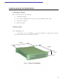
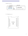
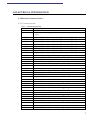
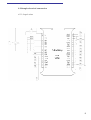
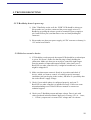
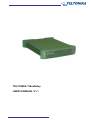
TELTONIKA T-BoxRelay
USER’S MANUAL V1.1
Legal Notice
Copyright © 2004 Teltonika.
All rights reserved. Reproduction, transfer, distribution or storage of part or all of the
contents in this document in any form without the prior written permission of Teltonika is
prohibited.
Nokia and Nokia Connecting People are registered trademarks of Nokia
Corporation.
Other product and company names mentioned herein may be trademarks or trade
names of their respective owners.
2
1.ABOUT THIS DOCUMENT
This document describes the T-BoxRelay hardware integration, configuration and
software configuration. This document should help T-BoxRelay integrators to integrate
and configure the system.
The document describes the mechanical and electrical installation and configuration.
Document also describes how to test and run T-BoxRelay for the first time.
3
2.INTRODUCTION
T-BoxRelay is an add-on for T-BoxN12R or T-Box/GPS-800, which enables to
switch high power devices via GSM network. T-BoxRelay has eight SPDT (single pole
double throw) relays inside, which can control eight high power devices. Usage of this
device is really wide: from everyday house control to complicated systems installed in
industrial companies.
T-BoxN12R was designed for M2M (machine to machine) applications or other
wireless solutions. Integrated Nokia 12 GSM module enables flexible wireless
communications over GSM network. All this, connected with T-BoxRelay, extends
opportunities to have a multiple system which ensure your intentions. Simply send SMS to
turn on house alarm, or use WAP to watch the condition of all house equipments.
Common, normally open and normally closed output contacts enables to connect
one device and have on/off function, or connect two devices and have 1stON(2ndOFF)
or 2ndON(1stOFF) function. For example, we can connect house heating system and
operate with it ON or OFF, or we can build a system which turns heating OFF when we
turn house alarm ON and vice-versa.
The light diodes in front of the device afford ground for seeing the indication of
power supply and watching in which state connected device is now. So it is easy to control
your T-BoxRelay and quickly find the problem in case of some troubles in one of the
devices.
All these features enable to use this mobile solution in wide range of applications.
4
3.MECHANICAL INTEGRATION
3.1.Package contents
These are the contents of your package:
1)
T-BoxRelay module,
2)
8x connectors MSTB 2,5 HC/3-ST, 5x connectors MSTB 2,5 HC/2-ST,
3)
CD with user manual,
4)
Quick start guide
3.2.Dimensions
3.2.1.T-BoxRelay case
The plastic case of T-BoxRelay is green and suitable for fitting with electronic
instruments that can hook to the DIN EN 50022.
118mm
100mm
31mm
Figure 1. Picture of T-BoxRelay
5
T-BoxRelay front panel
3.2.3.T-BoxRelay top view
6
4.ELECTRICAL INTEGRATION
4.1.Electrical characteristics
4.1.1.Connector pin-out
Table 1. Connector pin-out
Pin name
Description
GND
+
Device power. Voltage 12V DC. Power consumption 7875mW peak
up to.
IN2
IN3
IN4
IN5
IN8
IN9
IN7
IN6
NOP8
COM8
NCL8
NOP7
COM7
NCL7
NOP6
NCL1
COM1
NOP1
NCL2
COM2
NOP2
NCL3
COM3
NOP3
NCL4
COM4
NOP4
NCL5
COM5
NOP5
NCL6
COM6
NOP6
Input 2. Open collector input. 0…1V - true. 1…12V - false.
Input 3. Open collector input. 0…1V - true. 1…12V - false.
Input 4. Open collector input. 0…1V - true. 1…12V - false.
Input 5. Open collector input. 0…1V - true. 1…12V - false.
Input 8. Open collector input. 0…1V - true. 1…12V - false.
Input 9. Open collector input. 0…1V - true. 1…12V - false.
Input 7. Open collector input. 0…1V - true. 1…12V - false.
Input 6. Open collector input. 0…1V - true. 1…12V - false.
Normally open output 8. Active when signal is given to the input 8.
Common pin for NOP8 and NCL8
Normally closed output8. Active in default mode.
Normally open output 7. Active when signal is given to the input 7.
Common pin for NOP7 and NCL7.
Normally closed output7. Active in default mode
Normally open output6. Active when signal is given to the input 6.
Normally closed output1. Active in default mode
Common pin for NOP1 and NCL
Normally open output 1. Active when signal is given to the input1.
Normally closed output2. Active in default mode
Common pin for NOP2 and NCL2
Normally open output2. Active when signal is given to the input2.
Normally closed output3. Active in default mode
Common pin for NOP3 and NCL3.
Normally open output3. Active when signal is given to the input3.
Normally closed output4. Active in default mode
Common pin for NOP4 and NCL4
Normally open output4. Active when signal is given to the input4.
Normally closed output5. Active in default mode
Common pin for NOP5 and NCL5
Normally open output5. Active when signal is given to the input5.
Normally closed output6. Active in default mode
Common pin for NOP6 and NCL6.
Normally open output6. Active when signal is given to the input6.
7
4.1.2.Grounding
The ground for power supply is marked as “-“. Please ensure that polarity is correct
when connecting wires. The ground for the inputs and outputs remains the same.
4.1.3.Power supply
T-BoxRelay uses 12V direct current. Please use AC/DC converter to adjust your
household 220V to T-BoxRelay power supply. The same power source can be applied to
T-BoxN12R and this can make your scheme simpler.
4.1.4.Digital Inputs
There are seven open collector inputs. If the input voltage is less than 1V, relay
switches over, else, if input voltage is more than 1V (up to 12V), relay turns to default
position. The resistance of an input is about 2kΩ.
4.1.5. Outputs
There are three kinds of outputs in T-BoxRelay:
a) NCL output. Normally closed output, operates until the relay is switched, when
the input voltage is more than 1V.
b) NOP output. Normally open output, operates when les than 1V voltage is given
to the input and relay is switched.
c)
COM output. It is common output for both pins (NCL and NOP).
Outputs can hold 250V voltage and 10A (15A peak) current.
8
4.2.Sample electrical connection
4.2.1.Sample scheme
9
5. TROUBLESHOOTING
5.1.T-BoxRelay doesn’t power up
1) If the T-BoxRelay works well, the “PWR” LED should be always on.
Please make sure you have connected the power supply wires to TBoxRelay according the scheme (positive terminal of power supply to
pin 2 and GND to pin1) and that these wires are firmly holding the
connector.
2) Please make sure that your power supply (AC/DC converter or battery) is
12V and at least 500mA.
5.2.Failed to control a device
1) If T-BoxRelay works properly the output LEDs should be on when input
is given. If it doesn’t, make sure that the plug is firmly holding the
connection. Make sure that you are trying to control the right output.
Does the number of input and output coincide? Also check your TBoxN12R (or other control device), it might be breakdown, or wires
might be snapped off.
2) Make sure that output contact is firmly in its position and check if
device, which you want to control, is working properly in normal
conditions (just put the plug in the socket), and there is a possibility that
the socket doesn’t supply voltage.
3) Check if your mobile phone is configured properly, and your TBoxN12R (or other controller) is installed correctly. If there are some
misunderstandings read T-BoxN12R user manual or contact our
technical support.
4) Check your T-BoxRelay output and input voltage. Does it suit with
values produced in this document? Input can’t overstep 12V (0…1-true;
1…12-false), outputs can’t overrun 250V voltage and 10A current.
10
6.TECHNICAL SPECIFICATIONS
6.1.Mechanical specifications and operating conditions
Parameter
Min
Size
Weight
Storage temperature
Typical
Max
Unit
118 × 100 × 31
mm
148 ± 10
g
-40
+85
C0
6.2.Absolute maximum ratings
Parameter
Max
Unit
12
V
Maximum output current
10 (Peak to 15)
A
Maximum output voltage
250
V
Maximum digital input voltage
Maximum ratings are those values beyond which device damage can occur. Maximum ratings applied
to the device are individual stress limit values (not normal operating conditions) and are not valid
simultaneously. If these limits are exceeded, device functional operation is not implied, damage may occur and
reliability may be affected.
6.3.Electrical parameters
Parameter
Min
Power supply voltage
Peak power consumption
Typical
Max
Unit
12
V
7875
mW
Digital input high voltage
0
0.99
V
Digital input low voltage
1
12
V
Digital input resistance
20
kΩ
11
7.TECHNICAL SUPPORT
If you encounter any problems when using our products, please refer to
Troubleshooting on page 11. If you do not find a solution for your problem, please contact
our technical support by writing an e-mail to [email protected] . We will be pleased to
help you.
If you are interested in other products from Teltonika, please visit our website
www.teltonika.lt, where you will find our newest products.
If you are interested in product pricing or want to order our products with different
antennas, connectors or built-in programs, please contact our sales department by writing
an e-mail to [email protected] .
12