1
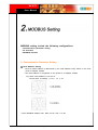
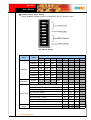
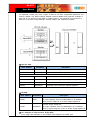
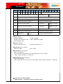
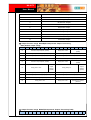
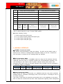
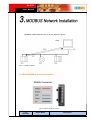
NA-9173
User Manual
Copyright(C) * CREVIS Co.,Ltd * Support +82-31-273-6452 * URL : www.crevis.co.kr
-1-
NA-9173
User Manual
List of Revisions
No.
1
Date
2007.12.15
Version
1.00
Revision
created
Copyright(C) * CREVIS Co.,Ltd * Support +82-31-273-6452 * URL : www.crevis.co.kr
-2-
NA-9173
User Manual
Contents
1. Product Specification
1) General Specifications
2) MODUBS RS485 Communication Specification
2. MODBUS Setting
1) Communication parameter setting
2) I/O allocation
3) MODBUS Interface
3. DeviceNet Network Installation
1)
2)
3)
4)
5)
RS485-MODBUS Electrical Interface
Cables
Data Signaling Rates
Maximum number of device without repeater
Length
4. Check Operation Status
1)
2)
3)
4)
5)
MOD : Module Status LED
RXD : Received Data LED
TXD : Transmit Data LED
I/O : Expansion Module Status LED
Field Power : Field Power Status LED
Copyright(C) * CREVIS Co.,Ltd * Support +82-31-273-6452 * URL : www.crevis.co.kr
-3-
NA-9173
User Manual
1) General Specifications
Item
Temperature
Humidity
Specifications
Operating
-0℃ to +60℃ (32℉ to 140℉)
Storage
-40℃ to +85℃ (-40℉ to 185℉)
Operating
5 to 95% RH (Non-condensing)
Storage
5 to 95% RH (Non-condensing)
Vibration immunity
10 TO 55Hz,double amplitude of 0.75mm,
10minutes on each of 3 axes (X,Y,Z)
Shock Immunity
Peak acceleration and duration 15g/11ms, 3times
on each of 3 axes (X,Y,Z)
Capsuling
Din rail or screw tightening
Remarks
2) MODBUS RS485 Communication Specification
Item
Specification
Network Protocol
RTU and ASCII
Network length
1200m (RS485)
Number of Nodes
64 Nodes
Communication speed
1200, 2400, 4800, 9600, 19200, 38400,
57600, 115200bps
Number of Expansion I/O
Max. 32 Slots
Interface Connector
Dsub 9Pin (Female)
Settable Node Address
1~99 with two rotary switches
Indicator
5LEDS
1Green/Red, Module Status (MOD)
1Green,Received Data (RXD)
1Green,Transmit Data (TXD)
1Green/Red, Expansion Module Status (I/O)
1Green,Field Power Status
System Power
Supply voltage : 24Vdc nominal
Supply voltage range : 11~28.8Vdc
Protection : Output current limit (Min.1.5A)
Reverse polarity protection
Isolation
System power to internal logic : Non-isolation
System power to I/O Driver : Isolation
Copyright(C) * CREVIS Co.,Ltd * Support +82-31-273-6452 * URL : www.crevis.co.kr
Remarks
Dip Switch
Setting
-4-
NA-9173
User Manual
MODBUS setting include the following configurations:
- Communication parameter setting
- I/O allocation
- MODBUS Interface
1) Communication Parameter Setting
◆ Node Address Setting
- NA-9173 Node address is determined by the node address rotary switch on the front
panel of adapter module.
- Set node address is recognized on the power-on of adapter module.
Ex) When node address is set as 27:
Device MAC ID Setting :( 2*10 + 1*7 )= 27
* Each MODBUS Adaptor has MAC ID No. from 0 to 99.
Copyright(C) * CREVIS Co.,Ltd * Support +82-31-273-6452 * URL : www.crevis.co.kr
-5-
NA-9173
User Manual
◆ Communication Speed Setting
Setting MODBUS Adapter Interface Configuration with 8 Pole DIP Switch
Dip Switch Setting
Item
Baudrate
WatchDog
Byte Format
RTU/ASCII
Setup
DIP Switch
#1
#2
#3
1200bps
OFF
OFF
OFF
2400bps
ON
OFF
OFF
4800bps
OFF
ON
OFF
9600bps
ON
ON
OFF
19200bps
OFF
OFF
ON
38400bps
ON
OFF
ON
57600bps
OFF
ON
ON
115200bps
ON
ON
ON
#4
#5
#6
#7
8bit, No Party, 1Stop
OFF
OFF
OFF
8bit, Even Party, 1Stop
ON
OFF
OFF
8bit, Odd Party, 1Stop
OFF
ON
OFF
8bit, No Party, 2Stop
ON
ON
OFF
7bit, No Party, 2Stop*
OFF
OFF
ON
7bit, Even Party, 1Stop*
ON
OFF
ON
7bit, Odd Party, 1Stop*
OFF
ON
ON
8bit, No Party, 1Stop
ON
ON
ON
Disable
OFF
Enable
ON
RTU Mode
Mode
ASCII
* Possible in ASCII Mode only
#8
OFF
ON
2) I/0 Allocation
Copyright(C) * CREVIS Co.,Ltd * Support +82-31-273-6452 * URL : www.crevis.co.kr
-6-
NA-9173
User Manual
An expansion module may have 3 types of data as I/O data, configuration parameter and
memory resister. The data exchange between network adapter and expansion modules is
done via an I/O process image data by FnBus protocol. The following figure shows the
data flow of process image between network adapter and expansion modules.
MODBUS Interface Resister/Bit Map
◆ Resister Map
Start Address
Read/Write
Description
0x0000
Read
Process Input image resisters
0x0800
Read/Write
Process output image registers
0x1000*
Read
Adapter Identification special registers.
0x1020*
Read/Write
Adapter Watchdog, other time special register.
0x1100*
Read/Write
Adapter Information special registers.
0x2000*
Read/Write
Expansion Slot Information Special registers
*The special register map must be accessed by read/write of every each address (one address)
◆ Bit Map
Start Address
Read/Write
Description
Process input image bits
0x0000
Read
All input registers area are addressable by bit address.
Size of input image bit is of input image register*16.
Process output image bits
0x1000
Read/Write
All output registers area are addressable by bit address.
Size of output image bit is size of output image register*16
◆ For Example of Input Process Image Data
Input image data depends on slot position and expansion slot data type.
Copyright(C) * CREVIS Co.,Ltd * Support +82-31-273-6452 * URL : www.crevis.co.kr
-7-
NA-9173
User Manual
Input process image data is only ordered by expansion slot position when input image
mode is uncompressed (mode 0,2). But, When input image mode is compressed (mode
1,3), input process image data is ordered by expansion slot position and slot data type.
Slot Address
Module Description
0
MODBUS Adaptor
1
4-Discrete input
2
8-Discrete input
3
2-Analog input
4
16-Discrete input
5
4-Discrete input
6
8-Discrete input
7
4-Discrete input
8
2-Analog input
9
16-Discrete input
10
4-Discrete input
◆ Input Process Image Mode#0
(Status(1word) + Uncompressed Input Processing Data)
Copyright(C) * CREVIS Co.,Ltd * Support +82-31-273-6452 * URL : www.crevis.co.kr
-8-
NA-9173
User Manual
WORD#
#15
#14
#13
#12
#11
#10
#9
#8
#7
+0
EW
EC
0
0
0
0
0
ES
FP
#6
#5
#4
#3
#2
#1
#0
FnBUS Status
Discrete Input 4points
(slot#1)
+1
Discrete Input 8points (slot#2)
Empty,Always 0
+2
Analog Input CH0 High byte (slot#3)
Analog Input CH0 low byte (slot#3)
+3
Analog Input CH1 High byte (slot#3)
Analog Input CH1 low byte (slot#3)
+4
Discrete Input high 8points (slot#4)
Discrete Input low 8points (slot#4)
+5
Discrete Input 8points (slot#6)
Empty,Always 0
Discrete Input 4points
(slot#5)
+6
Analog Input CH0 low byte (slot#8)
Empty,Always 0
Discrete Input 4points
(slot#7)
+7
Analog Input CH1 low byte (slot#8)
Analog Input CH0 high byte (slot#8)
+8
Discrete Input low 8points (slot#9)
Analog Input CH1 high byte (slot#8)
+9
Empty,Always 0
Discrete Input 4points
(slot#10)
●FnBus Status:
0:Normal Operation
2:FnBus Communication Fault
4:No Expansion Slot
●FP(Field Power)
0:24Vdc Field Power On.
●ES(MODBUS Error Setup)
0:No Error Setup
Discrete Input high 8points (slot#9)
1:FnBus Standby
3:Slot Configuration Failed
1:24Vdc Field Power Off
1:Error Setup
●EC(MODBUS Error Check)
0:No Error CRC/LRC
1:Error CRC/LRC three times more sequentially since its last restart,
clear counters operation, or power-up.
●EW(MODBUS Error Watchdog)
0:No Error Watchdog
1:Error Watchdog once more since its last restart, clear counters operation, or power-up.
◆ Input Process Image Mode#1
(Status(1word) + compressed Input Processing Data)
Copyright(C) * CREVIS Co.,Ltd * Support +82-31-273-6452 * URL : www.crevis.co.kr
-9-
NA-9173
User Manual
WORD#
#15
#14
0
#12
0
#11
0
#10
0
#9
0
#8
ES
#7
FP
#6
#5
#4
#3
#2
#1
#0
+0
EW
+1
Analog Input CH0 High byte (slot#3)
Analog Input CH0 low byte (slot#3)
+2
Analog Input CH1 High byte (slot#3)
Analog Input CH1 low byte (slot#3)
+3
Analog Input CH0 high byte (slot#8)
Analog Input CH0 low byte (slot#8)
+4
Analog Input CH1 high byte (slot#8)
Analog Input CH1 low byte (slot#8)
+5
Discrete Input low 8points (slot#4)
Discrete Input 8points (slot#2)
+6
Discrete Input 8points (slot#6)
Discrete Input high 8points (slot#4)
+7
Discrete Input high 8points (slot#9)
Discrete Input low 8points (slot#9)
Discrete Input 4points
Discrete Input 4points
Discrete Input 4points
Discrete Input 4points
(Slot#10)
(Slot#7)
(Slot#5)
(Slot#1)
+8
EC
#13
FnBUS Status
● Input Assembly Priority
1) Analog IO Data(Word Type)
2) 8 or 16 points Discrete IO Data(Byte Type)
3) 4 points IO Data(Bit Type)
4) 2 point IO Data(Bit Type)
◆ Input Process Image Mode#2
(Uncompressed Input Processing Data without Status),default input image
WORD#
#15
#14
#13
#12
#11
#10
#9
#8
#7
#6
#5
#3
#2
#1
#0
Discrete Input 4points
(slot#1)
+0
Discrete Input 8points (slot#2)
+1
Analog Input CH0 High byte (slot#3)
Analog Input CH0 low byte (slot#3)
+2
Analog Input CH1 High byte (slot#3)
Analog Input CH1 low byte (slot#3)
+3
Discrete Input high 8points (slot#4)
Discrete Input low 8points (slot#4)
+4
Discrete Input 8points (slot#6)
Empty,Always 0
Discrete Input 4points
(slot#5)
+5
Analog Input CH0 low byte (slot#8)
Empty,Always 0
Discrete Input 4points
(slot#7)
+6
Analog Input CH1 low byte (slot#8)
Analog Input CH0 high byte (slot#8)
+7
Discrete Input low 8points (slot#9)
Analog Input CH1 high byte (slot#8)
+8
Empty,Always 0
Discrete Input 4points
(slot#10)
Empty,Always 0
#4
Discrete Input high 8points (slot#9)
◆ Input Process Image Mode#3(Compressed Input Processing Data without
Status)
Copyright(C) * CREVIS Co.,Ltd * Support +82-31-273-6452 * URL : www.crevis.co.kr
- 10 -
NA-9173
User Manual
WORD#
#15
#14
#13
#12
#11
#10
#9
#8
#7
#6
#5
#4
#3
#2
#1
+0
Analog Input CH0 High byte (slot#3)
Analog Input CH0 low byte (slot#3)
+1
Analog Input CH1 High byte (slot#3)
Analog Input CH1 low byte (slot#3)
+2
Analog Input CH0 high byte (slot#8)
Analog Input CH0 low byte (slot#8)
+3
Analog Input CH1 high byte (slot#8)
Analog Input CH1 low byte (slot#8)
+4
Discrete Input low 8points (slot#4)
Discrete Input 8points (slot#2)
+5
Discrete Input 8points (slot#6)
Discrete Input high 8points (slot#4)
+6
Discrete Input high 8points (slot#9)
Discrete Input low 8points (slot#9)
+7
#0
Discrete Input 4points
Discrete Input 4points
Discrete Input 4points
Discrete Input 4points
(Slot#10)
(Slot#7)
(Slot#5)
(Slot#1)
*FnBus use the byte-oriented register mapping.
*Size of input image bit is size of input image register
● Input Assembly Priority:
1) Analog Input Data (Word type)
2) 8 or 16 points Discrete Input Data (Byte type)
3) 4 Points Input Data(Bit type)
4) 8 Points Input Data(Bit Type)
◆ For Example of Output Process Image Data
Output image data depends on slot position and expansion slot data
type. Output process image data is only ordered by expansion slot
position when output image mode is uncompressed (mode 0). But, When
output image mode is compressed (mode 1), output process image data is
ordered by expansion slot position and slot data type.
Slot Address
0
Module Description
MODBUS Adaptor
Copyright(C) * CREVIS Co.,Ltd * Support +82-31-273-6452 * URL : www.crevis.co.kr
- 11 -
NA-9173
User Manual
1
4-Discrete Output
2
8-Discrete Output
3
2-Analog Output
4
16-Discrete Output
5
4-Discrete Output
6
8-Discrete Output
7
2-Relay Output
8
2-Relay Output
9
2-Analog Output
10
16-Discrete Output
11
4-Discrete Output
◆ Output Process Image Mode#0(Uncompressed Output Processing
Data),default output image
WORD#
#15
#14
#13
#12
#11
#10
#9
#8
#7
#6
#5
#4
#2
#1
Discrete output 8points (slot#2)
+1
Analog output CH0 High byte (slot#3)
Analog output CH0 low byte (slot#3)
+2
Analog output CH1 High byte (slot#3)
Analog output CH1 low byte (slot#3)
+3
Discrete output high 8points (slot#4)
Discrete output low 8points (slot#4)
+4
Discrete output 8points (slot#6)
Empty,Don't Care
Discrete
output
2points
(slot#8)
Empty,Don't Care
Discrete Input 4points
(slot#5)
Discrete
output
2points
(slot#7)
Empty,Always 0
+6
Analog output CH0 high byte (slot#9)
Analog output CH0 low byte (slot#9)
+7
Analog output CH1 high byte (slot#9)
Analog output CH1 low byte (slot#9)
+8
Discrete Output high 8points (slot#10)
Discrete Output low 8points (slot#10)
+9
Empty,Don't care
Empty,Don't care
#0
Discrete output 4points
(slot#1)
+0
+5
Empty,Don't Care
#3
Discrete Out 4points
(Slot#11)
◆ Output Process Image Mode#1(Compressed Output Processing Data)
WORD#
#15
#14
#13
#12
#11
#10
#9
#8
#7
#6
#5
#4
#3
Copyright(C) * CREVIS Co.,Ltd * Support +82-31-273-6452 * URL : www.crevis.co.kr
#2
#1
#0
- 12 -
NA-9173
User Manual
+0
Analog output CH0 High byte(slot#3)
Analog output CH0 low byte(slot#3)
+1
Analog output CH1 High byte(slot#3)
Analog output CH1 low byte(slot#3)
+2
Analog output CH0 high byte(slot#9)
Analog output CH0 low byte(slot#9)
+3
Analog output CH1 high byte(slot#9)
Analog output CH1 low byte(slot#9)
+4
Discrete output low 8points(slot#4)
Discrete output 8points(slot#2)
+5
Discrete output 8points(slot#6)
Discrete output high 8points(slot#4)
+6
Discrete Input high 8points(slot#10)
Discrete Input low 8points(slot#910)
+7
Discrete
output
2points(slot
#8)
Discrete
output
2points(slot
#7
Discrete
output4points(Slot#11)
Discrete output
4points(Slot#5)
Discrete output
4points(Slot#1)
*FnBus uses the bytes-oriented register mapping.
*Size of output image bit is size of output image register.
● Output Assembly Priority:
1) Analog Output Data (Word type)
2) 8 or 16 points Discrete Output Data (Byte type)
3) 4 Points Output Data (Bit type)
4) 2 Points Output Data (Bit Type)
3) MODBUS INTERFACE
◆ MODBUS Transmission Mode
Two different serial transmission modes are defined : The RTU and the ASCII mode. It
defines the bit contents of message fields transmitted serially on the line. It determines
how information is packed into the message fields and decoded.
◆ RTU Transmission Mode
When devices communicate on a MODBUS serial line using the RTU (Remote Terminal
Unit)mode, each 8-bit byte in a message contains two 4-bit hexadecimal characters. The
main advantage of this mode is that its greater character density allows better data
throughput than ASCII mode for the same baudrate. Each message must be transmitted in
a continuous stream of characters.
Start
Address
Function
Data
CRC Check
End
≥3.5 char
1 char
1 char
Up to 252 char(s)
2 chars
≥3.5 char
◆ ASCII Transmission Mode
When devices are setup to communicate on a MODBUS serial line using ASCII (American
Standard Code for Information Interchange) mode, each 8-bit byte in a message is sent as
two ASCII characters.
This mode is used when the physical communication link or the capabilities of the device
dose not allow the conformance with RTU mode requirements regarding timers management.
Copyright(C) * CREVIS Co.,Ltd * Support +82-31-273-6452 * URL : www.crevis.co.kr
- 13 -
NA-9173
User Manual
Start
1 chars
Address
2 chars
Function
2 chars
Data
LRC Check
Up to 2x252 char(s) 2 chars
End
2 chars CR,LF
◆ Support MODBUS Function Codes
Function Code
Function
Description
Unicast/Broadcast
1(0x01)
Read Coils
Read output bit
Unicast
2(0x02)
Read Discrete Inputs
Read input bit
Unicast
3(0x03)
Read Holding Registers Read Output Word
Unicast
4(0x04)
Read Input Registers
Read input word
Unicast
5(0x05)
Write Single Coil
Write one bit output
Unicast/Broadcast
6(0x06)
Write Single Registers
Write one word output
Unicast/Broadcast
8(0x08)
Diagnostics
(Serial Line only)
Read diagnostic
register
Unicast
15(0x0F)
Write Multiple Coil
Write a number of
output bits
Unicast/Broadcast
16(0x10)
Write Multiple registers
Write a number of
output words
Unicast/Broadcast
Read/Write Multiple
registers
Read a number of
input words
/ Write a number of
output words
Unicast
23(0x17)
Copyright(C) * CREVIS Co.,Ltd * Support +82-31-273-6452 * URL : www.crevis.co.kr
- 14 -
NA-9173
User Manual
MODBUS RS485 Network Set up is like following figure1.
Figure 1 MODBUS Network
1) RS485-MODBUS Electrical Interface
Figure 2 RS485 MODBUS Interface
5 pin
connector
Signal Name
Description
Copyright(C) * CREVIS Co.,Ltd * Support +82-31-273-6452 * URL : www.crevis.co.kr
- 15 -
NA-9173
User Manual
1
RXD/TXD+
In/Out, Transceiver Data High
2
RXD/TXD-
In/Out, Transceiver Data Low
3
GND
Signal Common
4
Shield
Shield
5
FG
Frame Ground
Internally Shorted with Shield
2) Cables
A MODBUS over Serial Line Cable must be Shielded. At One of each cable its shield must
be connected to protective ground. If a connector is used at this end, the shell of the
connector is connected to the shield of the cable.
3)Data Signaling Rates
9600bps and 19.2kbps are required and 19.2 is the required default Other baud rates may
optionally be implemented : 1200, 2400, 4800,..., 38400bps, 57600bps, 115.2kbps.
4) Maximum number of device without repeater
A figure of 32 device is always authorized on any RS485-MODBUS system without repeater.
Depending of :
- all the possible addresses.
- the figure of RS485 Unit Load used by the device.
- and the line polarization in need be.
RS485 system may implement a larger number of devices. Some devices allow the
implementation of a RS485-MODBUS serial line with more than 32 devices, without repeater.
In this case these MODBUS devices must be documented to say how many of such
devices are authorized without repeater. The use of a repeater between two heavy loaded
RS485-MODBUS is also possible.
5) Length
The end to end length of trunk cable must be limited. The maximum length depends on the
baudrate, the cable, the number of loads on the daisy chain, and the network configuration
For a maximum 9600 Baudrate and AWG26 gauge, the maximum length is 1200m.
Copyright(C) * CREVIS Co.,Ltd * Support +82-31-273-6452 * URL : www.crevis.co.kr
- 16 -
NA-9173
User Manual
When all installation and configuration processes are complete, the adaptor module status
LED (MOD LED) and Communication status LED shall be lit in a green color. If not, it
indicates that an error has occurred. See the following table for proper measures.
1) MOD : Module Status LED
State
LED is
Description
No Power
Off
No power is supplied to the unit
Device Operational
Green
The unit is operating in normal condition
Flashing
The device needs commissioning due to configuration
Green
missing, incomplete or incorrect.
Green/Red
MODBUS error such as watchdog error, CRC/LRC
Toggle
error, Setup dip switch,error,etc.
Flashing
Recoverable Fault
Red
-EEPROM sum check error
Device in Standby
MODBUS Error
Minor Fault
Unrecoverable Fault
The device has an unrecoverable fault.
Red
-Memory error or CPU watchdog error.
2) RXD : Received Data LED
State
Not Powered
LED is
Off
Adapter received correct Green
message frame
Flashing
Description
Device is idle or may be not powered
Adapter(Slave) received correct frame which address
to the slave or broadcast. About 20msec flashing.
3) TXD : Transmit Data LED
State
LED is
Description
Not Powered
Off
Device is idle or may be not powered
Adapter transmit frame
Green
Flashing
Adapter(Slave) transmit frame. About 20msec flashing.
4) I/O : Expansion Module Status LED
State
LED is
To Indicate
Copyright(C) * CREVIS Co.,Ltd * Support +82-31-273-6452 * URL : www.crevis.co.kr
- 17 -
NA-9173
User Manual
Not Powered
No Expansion Module
Off
Device has no expansion module or may not be
powered
FnBus Connection
Do not Exchanging I/O
Flashing
Green
FnBus is Normal but does not exchange I/O data
(Passed the expansion module configuration)
FnBus Connection,
Run Exchange I/O
Green
Exchange I/O data
FnBus connection fault
During Exchanging I/O
Flashing
Red
One or more expansion module occurred in fault state
- Changed expansion module configuration
- FnBus communication failure
Failed to initialize expansion module
- Detected invalid expansion module ID.
- Overflowed Input/Output Size
- Too many expansion module
- Initial protocol failure
- Mismatch vender code between adapter and
expansion module.
Expansion Configuration
Red
Failed
5) Field Power : Field Power Status LED
State
LED is
To Indicate
Not Supplied Field Power
Off
Not supplied 24Vdc field power
Supplied Field Power
Green
Supplied 24Vdc field power
Copyright(C) * CREVIS Co.,Ltd * Support +82-31-273-6452 * URL : www.crevis.co.kr
- 18 -