1
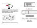
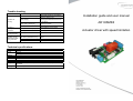
Trouble shooting
Error
Cause
Defect print.
Solution
Check that actuator is connected to
terminal 1 and 6 on X1.
Check that the supply at X3 is
correctly polarized and that the fuse
is not defect.
Check that the plug is placed
correctly in socket.
Contact your dealer.
Check that the plug is placed
correctly in socket.
Contact your dealer.
Defect print.
Contact your dealer.
Wires not mounted correctly.
Faulty supply.
Actuator not
running
Faulty wire to switch(es).
Defect print.
Actuator is
running but stops
irregularly.
Actuator only
running one way.
Actuator running
without the button
being activated.
Faulty wire to switch(es).
DIP switch positioned wrong
Wire to switch defect.
Defect print.
See Section about setting of DIP
switch
Check wire.
Contact your dealer.
Technical specifications
Input
Voltage
Power
Output
Voltage
Power
Life span
Duty cycle
24VDC
Max. 8A
Standby power: 30mA
24VDC
Max. 8A
The expected life span of the processors is approximately 10 year at 30 daily
operations.
10% - 6 min. per hour
Installation guide and user manual
AD1HSMINI
Actuator driver with speed limitation
Plug
Functional description
X3
X1
Pin
1
2
1
2
3
4
5
6
Connection
0VDC
+24VDC
Actuator output (+/-)
N/C
N/C
N/C
N/C
Actuator output (-/+)
Function
24V supply
Socket to Actuator
The switch or switches connected to AD1HS via a 3.5mm jack plug.
AD1HS
MINI
AD1HSMINI is a driver for control of an actuator/motor so that it can be
controlled independently of the electronics of the chair. It is a separated
unit and is as such not dependent on the type of chair it is mounted on. For
the same reason it is necessary to turn the chair on to activate the actuator
through AD1HSMINI.
AD1HSMINI is controlled by one or two switches. If two switches are used,
one switch is operated for each direction. By one switch the actuator/motor
direction is toggled each time the button is activated.
It is possible to set the maximal movement speed of the actuator.
3.5mm
Jack plug
Pin
Connection
Description
Tip
COMMON
Common pin for the switches
Ring
SWITCH2
Sleeve
SWITCH1
Connection for second switch for ”2 switch control”.
Normally Open.
Connection for first switch.
Normally Open.
The DIP switch is used to decide whether AD1HSMINI is operated by one
or two switches.
DIP switch
1
2
ON
OFF
One switch
Two switches
Not used
Adjustment of speed
The speed of the actuator/motor can be set by adjusting trimmer R5 on the
print. The speed is variably set by turning the trimmer. The trimmer is
single-turn and is not updated during operation of the actuator.
Trimmer
R4
R5
Fitting instruction
AD1HSMINI is supplied with 24V voltage. The actuator is connected to the
output.
Function
No function
Speed