1
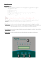
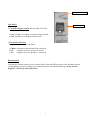
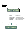
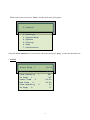
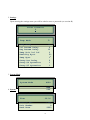
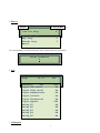
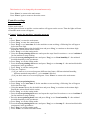
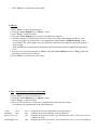
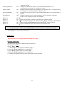
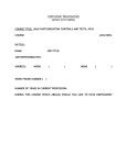
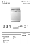
Controller user manual Contents: Controller’s setup The program map Controller settings page 3 4 8 Controller set-up Front board (door) 1. Leds : indicating whether the application is on or off. (Light is on- application is on; light is off- application is off). #1- Main desiccant pump #2- Main blowers #3- Regenerator (including: minor desiccant pump, water pump and blower) #4 - (optional): electrical tap, dumper #5- Heater/hot water pump Bypass Machine is working without the controller (in which case all other lights are off) Warning: The door is locked by buckles on its left side. They should be opened and closed carefully while administering counter-support to the fuse box. 2. Prog. Button- is used to enter the sub-menus from the main menu and to change the variables. (press once to enter edit mode - a flickering line will appear below the variable to be edited, press again to move to the next variable or to exit the edit mode). 3. Arrow buttons- are used to navigate within the menus and to change the variables’ values while in edit mode. 4. Enter button- is used to enter the main menu from the main screen and to exit the menus. 1 2 3 2 4 Bypass switch Left Panel: Electrical switches 1. Controller bypass switch (has the shape of a lock) has 2 states: a. On- machine is working in controller bypass mode b. Off- machine is working in normal mode 2. Electrical switch box: Inside the box there are 3 switches: a. Main - disconnects the machine from electricity b. F1 - supplies current to groups #1 and #2 c. F2 - supplies current to groups #3, #4 and #5 Bottom panel: Contains the entrance points of the electrical cables from the different parts of the machine and the corresponding sensors according to the electrical scheme (see attached drawing: Power electric diagram – electricity and control box) 3 Program map Main screen Current Temperature Current Humidity Current Time 25.3°C 85.4% 12:23 Normal Auto Current State: ! Normal Auto ! Normal Manual ! Not Operational ! Low Limit ! High Limit ! Regenerator Limit ! Temperature Failure ! ! ! ! Humidity Failure Control Input Bypass Mode Thermostat Machine is working in automatic mode Machine is working in manual mode Machine is not working Desiccant level is too low Desiccant level is too high Desiccant concentration is too high Temperature sensor is not connected/not working Humidity sensor is not connected/not working Machine is activated by computer Machine is activated by controller bypass Hot water temperature is too low * Fast approach to view target humidity and temperature values: While at the main screen press the button. The following screen will appear for 5 seconds : Target Temp Target Humidity 25.0°C 75.0% 4 While at the main screen press ‘Enter’ and the main menu will appear : 1. Control 2. Settings 3. System Mode 4. System 5. History 6. Test 7. Calibration Using the arrow buttons move between the sub-menus and press ‘prog.’ to enter the desirable one. 1. Control Start Time 1 End Time 1 From Humidity To Temp 1 Start Time 2 End Time 2 From Humidity To Temp 2 10:00 1 2 18:00 80% 30° 00:00 00:00 0% 0° 5 2. Settings Upon entering the settings menu you will be asked to enter a password (see section G) Enter Password 0 Temp Mode 0 Stop Delay Lvl Resume Delay Reg Resume Delay Temp Unit 0=C 1=F Humidity Hyst. Temp Hyst. Group Act Delay Group #4 Operative Group #5 Operative 10 2 15 0 2% 10 2 1 1 3. System Mode System Mode AUTO MAN OFF 4. System Time History Res. Unit Number Baud Rate 00:00 1 Day 0 9600 6 5. History Event # of events Low Lvl Stop 2 High Lvl Stop Reg Stop Thermo Stop Reset 1 5 3 To reset the data you will be asked to enter a password (see section G) Enter Password 0 6. Test Temp 24.00 459 Humidity 44% Input Low Level Input High Level Input Regenerator Input Control Input Thermostat Input Bypass Relay #1 Relay #2 Relay #3 Relay #4 Relay #5 405 ON ON ON ON ON OFF ON ON ON ON ON 7. Calibration 7 This function is to be changed by the manufacturer only. Press ‘Enter’ to return to the main menu. Press ‘Enter’ again to return to the main screen. Controller settings Primary settings Lift the main switch. All the lights will turn on and the version number will appear on the screen. Then the lights will turn off and the main screen will appear. 1.Control - Setting the machines' operating program 1.1 a. Press ‘Enter’ to enter the main menu. b. Press ‘Prog’ to enter the control menu. c. Press ‘Prog’ to set 'start time 1' for the machine to start working, a flickering line will appear below the hour-digit. d. Using the arrows choose the desirable hour and press ‘Prog’ to continue to the minute-digit. Repeat the actions listed in this section. e. Press ‘Prog’ to exit the setting mode. f. Press the arrow pointing down once and repeat the steps listed in sections c-e to set 'end time 1 for the machine to stop working. g. Press the arrow pointing down once and press ‘Prog’ to set 'from humidity 1' - the minimal desirable humidity in the greenhouse. h. Press ‘Prog’ to exit the setting mode. i. Press the arrow pointing down once and press ‘Prog’ to set 'to temp 1' - the maximal desirable temperature in the greenhouse. j. Press ‘Prog’ to exit the setting mode. k. There are 2 options : (1) If you want to set a second program (different time frame, different minimal humidity, different maximal temperature) – go to section 1.2 below. (2) If you don't want to set a second program - Press ‘Enter’ to return to the main menu. 1.2 a. Press the arrow pointing down. b. Press ‘Prog’ to set 'start time 2' for the machine to start working, a flickering line will appear below the hour-digit. c. Using the arrows choose the desirable hour and press ‘Prog’ to continue to the minute-digit. Repeat the actions listed in this section. d. Press ‘Prog’ to exit the setting mode. e. Press the arrow pointing down once and repeat the steps listed in sections c-e to set 'end time 2 for the machine to stop working. f. Press the arrow pointing down once and press ‘Prog’ to set 'from humidity 2' - the minimal desirable humidity in the greenhouse. g. Press ‘Prog’ to exit the setting mode. h. Press the arrow pointing down once and press ‘Prog’ to set 'to temp 2' - the maximal desirable temperature in the greenhouse. i. Press ‘Prog’ to exit the setting mode. j. Press ‘Enter’ to return to the main menu. 8 2. Settings a. Press ‘Enter’ to enter the main menu b. Using the arrow buttons go to ‘settings’ menu. c. Press ‘Prog’ to enter the menu. d. Password screen will appear. Enter the password as described below, you will then enter the settings menu. e. Press ‘Prog’ to set the desirable variable, a flickering line will appear below the digit. f. Using the arrow buttons choose the desirable value. Press ‘Prog’ to exit the setting mode. Set the variables according to the following table: Temp Mode Stop Delay Lvl Resume Delay Reg Resume Delay Temp Unit 0=C 1=F Humidity Hyst. Temp Hyst. Group Act Delay Group #4 Operative Group #5 Operative 0 10 2 15 0 2% 10 2 1 1 To be used according to manufacturer’s directives only Choose ‘1’ if the group is activated by the machine and ‘0’ if it is not g. Using the arrow buttons move to the next variable and repeat sections e-f. Repeat until all Variables are set. h. Press ‘Enter’ to return to the main menu 3. System-Mode - Setting a. Press ‘Enter’ to enter the main menu b. Using the arrow buttons go to ‘system mode’ menu. c. Press ‘Prog’ to enter the menu. d. Press ‘Prog’ for adjustment of the work mode. A flickering line will appear below the variable being processed. e. Using the arrow buttons choose the desirable option and press ‘Prog’ to exit the setting mode. f. Press ‘Enter’ to return to the main menu 4. System - Adjustment of the current time a. Press ‘Enter’ to enter the main menu b. Using the arrow buttons go to ‘system’ menu. c. Press ‘Prog’ to enter the menu. d. Press ‘Prog’ to adjust the hour, a flickering line will appear below the hour-digit. e. Using the arrow buttons choose the desirable hour, press ‘Prog’ to pass to the minute-digit and repeat the actions in this section. 9 f. Press ‘Enter’ to return to the main menu. 5. History a. Press ‘Enter’ to enter the main menu b. Using the arrow buttons go to ‘history’ menu. c. Press ‘Prog’ to enter the menu. d. Using the arrow buttons move between the different categories. e. Check the number of stops which occurred. If there were stops which happened due to a toolow or too-high level of desiccant - see management options under “problem solving” in the user manual. The same applies for cases when the regenerator has stopped working more than 3 times a night. If the machine was stopped by the thermostat, check whether the heater supplies the appropriate heat. f. In order to reset the data navigate to ‘Reset’ using the arrow buttons and press ‘Prog’. Enter the password as described in section G. g. Press ‘Enter’ to return to the main menu. 6. Test - checking the machines' functioning a. Press ‘Enter’ to enter the main menu b. Using the arrow buttons go to ‘history’ menu. c. Press ‘Prog’ to enter the menu. d. Review the sections to see if they are compatible with the machine’s status . according to the explanations in the following table: Temp 24.00 Humidity 44% Input Low Level 459 405 ON Input High Level ON Displays the current temperature in the greenhouse Displays the current humidity in the greenhouse Displays the desiccant’s status: ON: normal level, OFF: level is too low, see “problem solving” Displays the desiccant’s status: ON: normal level, OFF: level is too high, see 10 Input Regenerator ON Input Control ON Input Thermostat ON Input Bypass OFF Relay #1 Relay #2 Relay #3 Relay #4 Relay #5 ON ON ON ON ON “problem solving” Displays the desiccant’s status: ON: normal concentration, OFF: concentration is too high, see “problem solving” Displays distal activation (by computer): ON: normal, OFF: was turned off by the computer or electrical bridge is disconnected. Displays the hot water status: ON: desirable temperature, OFF: temperature is too low. Displays activation by a controller bypass: ON: activated by controller bypass, OFF: normal activation by controller Each relay activates a group as described in “controller setup” One can turn the group on or off by pressing ‘Prog’, moving to the desirable state using the arrow buttons and pressing ‘Prog’ again to choose *After 5 minutes the relay will return to its previous state NOTE: The relays activated within the test-‐menu will automatically return to the state which was previously set within the control menu immediately after exiting the Test mode. e. Press ‘Enter’ to return to the main menu. 7. Calibration This function is to be changed by the manufacturer only. Entering a password In certain cases you will be asked to enter a password. The password is 1234 a. Press ‘Prog’ A flickering line will appear beneath the digit ‘0’. b. Using the arrow buttons move to the digit ‘1’. c. Press ‘Prog’ again to move to the next digit. d. Using the arrow buttons move to the digit ‘2’. e. Continue accordingly until you have entered the whole password. 11