1
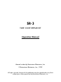
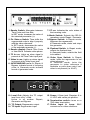
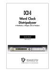
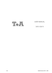
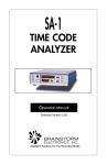
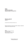
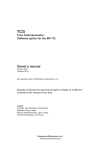
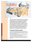
SR-3
TIME CODE
REPAIR KIT
Operation Manual
BRAINSTORM
ELECTRONICS, INC.
...Intelligent Solutions For The Recording Studio
SR-3
TIME CODE REPAIR KIT
Operation Manual
Manual written by Brainstorm Electronics, Inc.
© Brainstorm Electronics, Inc., 1999
All rights reserved. No part of this publication may be reproduced in any form
without prior written permission by Brainstorm Electronics, Inc.
1. Reader Switch: Alternates between
Time Code and User Bits.
In SET mode, increases the value of
the selected parameter (+).
7. CF LED: Indicates the color status of
the incoming code.
2. Fix Video ø Switch: Time shifts the
regenerated code to align it properly
with the video reference.
In SET mode, decreases the value
of the selected parameter (-).
9. Bypass Switch: In Repair mode,
bypasses the regenerator;
In Generate mode, starts and stops
the generator.
3. Reader display: Reads Time Code
or User Bits & indicates video phase.
4. TC In LED: Lights up when signal is
present at the Time Code input jack.
5. Video In LED: Lights up when signal
is present at the Video input jack.
6. 24/25/30ND/30D LED’s: In Repair &
Bypass, indicate format of incoming
code; in Generate mode indicate
format of generated code.
TIME CODE
OUTPUT
INPUT
Level Out
8. Mode Switch: Selects the SR-3’s
operations mode: Repair / Generate.
10. Flywheel Switch: In Repair mode,
selects the flywheel time;
In Generate mode, selects the field
to be edited.
11. Video Sync Switch: In Repair
mode, locks the regenerator to ext
video reference;
In Generate mode, locks the
generator to video reference if
available or pulls down rate if ext.
video is not present (i.e. 29.97)
POWER
6-9VDC
@ 500ma
VIDEO
Off
75Ω
Termination
LOOP
IN
12. Level Out: Adjusts the TC output
level from off to +12db.
Active in all modes: Repair,
Generate and Bypass
15. Power: 2.5mm jack. Requires 6 to
12 VDC with center pin positive.
13. TC Output: Regenerator output.
17. Video Input & Loop: BNC
connectors for video reference.
14. TC Input: Regenerator input
16. Termination switch: turns on a
75Ω video termination.
Introduction
Page 1
Introduction
The SR-3 Time Code Repair Kit is a regenerator designed to repair
bad time code. It’s three main functions are to repair drop outs,
reduce jitter and correct video phase. It also reads time code,
identifies its format and analyzes its phase with video.
The SR-3 also generates all standard time code formats referenced
to internal crystal or to external video.
Table of contents
• Introduction ........................................................................................ 1
• Setting up the SR-3 ............................................................................. 2
Connections ................................................................................ 2
Wiring ....................................................................................... 2
• Modes of Operation ........................................................................... 3
• Repair Mode ......................................................................................
Reader display & format LED’s .......................................................
Flywheel Time .............................................................................
Video Sync .................................................................................
What does it mean to be in phase with video? ......................
Checking video phase with the SR-3 .....................................
Locking the regenerator to external video ..............................
Correcting video phase ........................................................
Bypassing the Regenerator ...........................................................
Ramp-Up Time ............................................................................
3
3
4
5
5
5
6
6
7
7
• Generate Mode .................................................................................. 8
Reader display & format LED’s ....................................................... 8
Starting the generator .................................................................. 8
Preset Start Time .......................................................................... 8
Changing a preset ...................................................................... 8
Scrolling through the preset parameters......................................... 9
Frame rates & clock sources ....................................................... 10
• Output level and waveform ............................................................... 11
• Application Notes ............................................................................. 12
• Appendix ......................................................................................... 14
• Specifications ................................................................................... 17
Page 2
Set Up
Setting up the SR-3
1. Connections
➫ Time Code Input:
When repairing time code, connect your time code source
(raw time code) to this jack.
➫ Time Code Output:
This is the output of the generator in all modes (repair,
generate and bypass). Connect this jack to your time code
destination (reader, synchronizer, tape machine, ...).
➫ Video In & Loop:
Connect composite sync or composite video to the “Video In”
BNC connector. An additional BNC connector is provided for
looping through as well as a switchable 75Ω termination.
➫ Power:
The SR-3 requires 6 to 9VDC @ 500mA with center pin
positive.
2. Wiring
➫ 1/4” Jacks:
Time code input and output jacks are RTS 1/4” jacks
Pins are: Tip = high, Ring = low, Sleeve = ground.
Since time code is bi-phase, a reversal of low & high wires
would not cause a problem.
The SR-3 works with balanced and unbalanced equipment.
When using unbalanced equipment with the SR-3, wire your
cables as described in the diagrams below.
TIP
TIP
RING
SLEEVE
RING
SLEEVE
SR-3 Input
SR-3 Loop (out)
Figure 1. Proper unbalanced wiring diagrams
➫ BNC Connectors:
Use standard 75Ω video cables.
n.c.
Repair Mode
Page 3
Modes of Operation
The SR-3 has 2 modes of operation: Repair and Generate. The “Mode” switch to the right of the display toggles
between the 2 modes and the 2 led’s above the switch indicates which mode is currently selected.
Depending on the selected mode, some of the front panel
buttons have different functions. The functions for the Generate mode are indicated in reversed lettering on the front
panel. For example, the “Bypass” switch (in the Repair mode)
becomes the “Start” switch in the Generate mode.
Repair Mode
In Repair mode, the SR-3 continuously regenerates the input
time code, locked to either the source code or to external
video, performing repairs in the process, specifically drop
outs, jitter and video phase.
When the SR-3 is in the Repair mode, the “Repair” LED to the right of
the display is on. If it is off, press the “Mode” switch to turn it on.
1. Reader display & Format LED’s
The 8 digit display reads Time Code or User Bits. Use the
“Reader” switch to the left of the display to select one or the
other. The 2 LED’s to the left of the display indicate which is
currently selected (TC/UB).
The 5 LED’s under the reader display give additional information on the input signal:
• TC In: This LED indicates that signal is present at the TC input jack
• Vid In: This LED indicates that valid video is present at the
video input jack.
Page 4
Repair Mode
•24/25/30ND/30D: Only one of these LED’s is on at the
same time. It indicates the format of the repaired code.
• CF: This LED indicates the color status of the incoming code. It is on
if the color flag is set (bit 11); it is off if the flag is not set.
2. Flywheel Time
The Flywheel time is the time during which the SR-3 continues
generating code after it has detected an input error, such as a
drop out. If the error has not been resolved by the end of the
flywheel time, the SR-3 stops.
During a drop out, the SR-3 generates code at the same rate
it did just prior to the drop out. After the drop out, the SR-3
slowly resyncs to the incoming code. However, if after a drop
out, the offset between the generator (SR-3) and the input
code is greater than 1/4 frame (± 20 bits), the SR-3 stops
regenerating and displays an error message (SLIP).
The SR-3 has 3 preset flywheel times: 5 Fr / 15 Fr / infinity.
Infinity (∞) is identical to “15fr” except that, if valid code
does not reappear after 15 frames, the SR-3 disregards the
input and continues generating time code at the same rate
until the “Bypass (start)” switch is pressed. Once the SR-3 has
switched to this mode and disregards the input, the “TC In”
led goes off, even if input signal returns.
To change the flywheel time, press the “Flywheel” switch
until the proper time is selected. Flywheel time cannot be
changed while SR-3 is running.
Repair Mode
Page 5
3. Video Sync
What does it mean for time code to be in phase with video?
For time code to be synchronous with video, each word of
time code must coincide with one frame of video; to be phased
properly, the beginning of each word must coincide with the
beginning of the video frame it describes.
Each word of time code is made up of 80 bits, numbered
from 00 to 79 (see Figure 2 below). Time code is phased
properly with video when the end of bit 79 of time code lines
up with field 1 line 5 of video (F1L5), ± 1 line.
ONE TIME CODE FRAME (12:35:08:28)
Sync Word
64
68
72
76
Sync Word
0
F1L5
4
8
12
16
20
24
Video Field 1
28
32
36
40
44
48
F2L5
52
56
60
64
Video Field 2
68
72
76
0
4
F1L5
ONE VIDEO FRAME
Figure 2. Proper alignment of time code and video
How can you check video phase with the SR-3 ?
You can monitor the sync between the incoming time code and the
external video reference on the reader display. This feature is only
available if “Video Sync” is on and if video is present:
Press and hold the “FixVideo ø” switch: the reader now shows
which bit of the time code word lines up with video F1L5.
How to interpret the video phase display ?
With properly phased code, the display should read: “bit
79”. In the ‘real world’ however, things are different and
phase will often be slightly off. For example, if the display
reads “bit 68” or “bit 07”, the address track was possibly
misaligned on the VCR and your synchronizer may show
some slight sub-frame offset (i.e. 03,12, etc) when locked to
code like this. So long as you are within a few bits of 79 and
Page 6
Repair Mode
the bit number stays the same, you should have no problems.
WARNING: If the bit number drifts, time code is not
synchronous and may be useless for your application.
Locking the regenerator to external Video
When “Video Sync” is on, the SR-3 locks the regenerated
code to the incoming video reference. This is recommended
since video is a very stable reference.
• DRIFT: To avoid a drift between the input and the output
time code, video sync is only possible if the source code is
synchronous with video. Therefore if the incoming code is
non-synchronous, the SR-3 indicates “DRIFT” in the display as
a warning.
The SR-3 considers code non-synchronous if time code moves
by more than 5 bits with respect to video F1L5.
• VIDEO LOSS: While “Video Sync” is on, if video is
interrupted, the SR-3 stops and indicates “VID LOSS” in the
display.
• NO VIDEO: When activating ”Video Sync”, if no video
is present, the SR-3 indicates “NO VIDEO” for about one
second and flashes the Video Sync LED.
Correcting Video Phase
When locked to video, if time code is out of phase, the SR3 can shift the regenerated time code so it is in phase with
the video reference (see page 4 - what does it mean to be in
phase with video?).
To correct the video phase, both the “Video Sync” and the
“FixVideo ø” switches must be turned on.
NOTE: The “Fix Video ø” switch can only be activated if the
“Video Sync” switch is on and not while code is running.
Phase correction can only be accomplished if the rate (or
frequency) of the incoming code is synchronous with video. As
with “Video Sync” described above, if the source code drifts, the
SR-3 indicates a “DRIFT” message in the display.
Repair Mode
Page 7
4. Regenerator Bypass
When bypass is engaged, the input signal is fed directly to the
output without any bit correction or repair.
Manual Bypass
To manually activate the bypass mode, press the “Bypass” switch
so that the LED is on.
Auto Bypass:
In the Repair mode, the SR-3 automatically switches to bypass
whenever it detects non play speed code. This way, readable code
is always present at the output, even during search and wind.
When the SR-3 switches to Bypass, the Reader displays the
incoming code. However, the SR-3 is a play speed reader and if
high speed code is running through the SR-3, the Reader won’t
display it. When play speed code reappears, the SR-3 switches
back to repair and the Reader displays the regenerated code
again.
5. Ramp-up time
When Video Sync is on, the SR-3 must wait for the tape
transport to reach a stable speed before it can determine
how the incoming code lines up with the video reference.
Until this is established, the SR-3 cannot regenerate code.
Therefore, the SR-3 stays in bypass until the end of a preset
ramp-up time, then switches to Repair.
The SR-3 has 3 preset ramp-up times which are selected in
conjunction with the Flywheel time:
FLYWHEEL TIME
5 Fr
15 Fr
∞
RAMP UP TIME
5 fr
1.5 sec
3 sec
Under most circumstances, the 5Fr setting should be used. The
other settings should be used with slow transports.
Page 8
Generate Mode
Generate Mode
In the Generate mode, the SR-3 can generate all standard
formats and frame rates, referenced to internal crystal or to
external video.
To set the SR-3 to generate time code hit the “Mode” switch
until the “Generate” LED is on.
Reader Display & Format LED’s
In the Generate mode, the reader displays the output time
code. It can read Time Code or User Bits. Use the “Reader”
switch to select. TC or UB. The format LED’s indicate which format is generated.
Starting the Generator
To start the generator, hit the “Start” button. To stop the
generator, hit the “Start” button again. The Start LED is on
solid when the generator is running and flashing when it is
stopped.
Preset Start Time
The SR-3 always holds a preset in memory. This preset
includes: Start Time, User Bits and Format.
Whenever you start the generator, it begins counting from
the preset start time, no matter where you last stopped. To
start from another number, you need to change the preset.
Changing the preset
To change the preset, hit the “Flywheel (Select)” switch. This
brings you into the SET mode. - NOTE: You can only enter the
SET mode when the generator is stopped.
While in the SET mode, the selected parameter blinks. You can
scroll through the different parameters by tapping the “Flywheel
(Select)” switch and adjust them by using the + and - buttons.
Generate Mode
Page 9
To exit the SET mode and store the new preset in memory, hit
the “Start” button. This can be done at any time so you don’t
have to scroll through all the parameters if you don’t need
to edit them. After you exit the SET mode you can press the
“Start” button again to start the generator.
Scrolling though the preset parameters
If the reader is on TC when entering the SET mode, you can
edit the start time and the format; if it is on UB, you can edit
the user bits.
Adjusting Start Time & Format:
Set the reader to TC and press the “Flywheel (Select)” button:
• The Start Time has 4 fields: Hours, Minutes, Seconds and
Frames. Tap the “Flywheel (Select)” button to move from one
field to the next and, using the + and - keys, adjust each one
as needed.
After the Frames field, tapping the “Flywheel (Select)” button
one more time moves you to the Format.
• While setting the format, the LED corresponding to the
selected format is blinking. The standard formats are: 24, 25,
30ND, 30D. Tap the + or - button repeatedly until the desired
format LED blinks.
Pressing the “Flywheel (Select)” button again moves you out
of the SET mode and stores the new preset in memory
Adjusting User Bits:
Set the reader to UB and press the “Flywheel (Select)”
button:
• Each digit of the User Bits is adjusted separately. Tap the
“Flywheel (Select)” button to move from one digit to the next
and, using the + and - keys, adjust each one as needed.
After the eighth digit, hitting the “Flywheel (Select)” button
again moves you out of the SET mode and stores the new
preset in memory.
NOTE: When starting the generator, the display automatically
switches back to TC.
Page 10
Generate Mode
Frame Rates & Clock Sources
The SR-3 can generate time code at all standard frame rates,
locked to its internal crystal or to external video.
To lock to external video, turn the “Video Sync” switch on
and connect your video reference to the rear panel BNC connector.
If the “Video Sync” switch is on and no video is present, the “Video
Sync” LED blinks and the SR-3 generates code at a rate .1% slower.
This pull-down corresponds to the difference between regular
SMPTE rate (30 f/s) and the NTSC Color rate (29.97 f/s).
The following table shows the different frame rates and clock
sources:
VIDEO
EXT
SYNC VIDEO
SELECTED
FORMAT
FRAME
RATE
CLOCK
SOURCE
Off
n/a
30ND
30DF
25
24
30
30
25
24
Internal Xtal
Internal Xtal
Internal Xtal
Internal Xtal
On
None
30ND
30DF
25
24
29.97
29.97
24.97
23.97
Internal Xtal
Internal Xtal
Internal Xtal
Internal Xtal
On
NTSC
30ND
30DF
25
24
29.97
29.97
No Output *
23.97
Ext. Video
Ext. Video
N/A
Ext. Video
On
PAL
30ND
30DF
25
24
No Output **
No Output **
25
No Output **
N/A
N/A
Ext. Video
N/A
* with message “NOT PAL” in display
** with message “NOT NTSC” in display
Output
Page 11
Output Level & Waveform
Output level
The output level is always adjustable, in repair, generate or
even bypass, with the rear panel pot (located next to the output jack). It is adjustable from full off to +12db. This adjusted
level remains constant regardless of input level fluctuations.
Output Waveform
SMPTE & EBU Specs
Per SMPTE and EBU specifications, rise time limiting is used
to minimize crosstalk from time code into audio. A longer
rise time removes more high frequency components from its
waveform. SMPTE specs call for a 25µs rise time; EBU for
50µs. A third waveform is available from the SR-3: square
wave (1µs rise time)
Figure 3.
25 µs rise time
SMPTE specs
Figure 4.
50 µs rise time
EBU specs
Figure 5.
1 µs rise time
Square wave
SR-3 Output waveform (rise time)
☛ In Bypass, the rise time is set at approximately 2µs. This
way, high speed code can go through without being filtered.
☛In Repair and Generate, the output rise time is set at 25µs.
Page 12
Application Notes
Application Notes
Recording the repaired time code
One way to deal with bad code is to restripe on a new track,
running the damaged code through the SR-3 and recording
its output. This is the simplest solution, but it requires an empty
track and takes a little time.
In this situation, set the Flywheel Time to 15 frames and, if the
original code is synchronous with video, turn “Video Sync”
on, and “Fix Video ø” if necessary.
Repairing “on the fly”
If you don’t have an empty track or the time to re-stripe your
tape with repaired code, you can insert the SR-3 at the output
of your time code track and repair “on the fly”.
For example, if the time code on your master tape machine is
marginal and your synchronizer looses lock once in a while,
connect the output of your tape machine into the SR-3 and
feed the output of the SR-3 into your synchronizer. In this set
up the synchronizer no longer reads the raw time code off
the tape machine but the repaired code off the SR-3. The SR3 automatically switches to bypass in wind or search so you
always have valid code at the output of the SR-3.
SETTING THE PROPER FLYWHEEL TIME: In this set up (repairing “on the fly”), after you stop the master tape machine,
the synchronizer will continue seeing time code until the SR-3
stops. If your synchronizer does not read tallies but only time
code, there will be a delay between the time you stop the
master machine and the time the synchronizer stops the slave
machine.
If you set the flywheel time to 5 frames, this delay will be
virtually unnoticeable. Set the flywheel time to 15 frames
only if you don’t mind the 1/2 second delay or if you have
a time code error that requires 15 frames flywheel time to be
repaired.
Application Notes
Page 13
Infinity flywheel time
Infinity flywheel time is helpful when you need to add new
time code after the original code has stopped.
It is also helpful if the original code has become so corrupted
and useless that you need to replace it and you only want to
use the original code to give the SR-3 a starting number.
If you need to stay in sync with the source code, do not use
infinity unless the source code is synchronous with video. Set
to infinity, the SR-3 disregards the time code input after 15
frames of bad code and, from that point, a drift would most
likely occur between the source time code (input) and the
regenerated time code (output). However, if the SR-3 stays
locked to video and the source code is synchronous, no drift
will occur.
When repairing synchronous code, always turn on “Video Sync”
One of the problems the SR-3 can help reduce is jitter. Whenever the source time code is synchronous with video, you
should feed the video reference into the SR-3 and activate
“VideoSync”. Video is a much more stable clock than time
code and helps reduce jitter substantially.
Page 14
Appendix
Appendix A: Eight Digit Display
The eight digit display is mainly used to read Time Code and
User Bits. In repair mode, it reads the input signal; in generate
mode, the output. It is also used for the following:
Software version number
When the SR-3 is first turned on, the reader displays the
software version number for a few seconds.
Error Messages
Error descriptions appear in the display as soon as they
are detected - (see appendix D pg. 16)
Video Phase
While pressing and holding the “FixVideo ø” button, the
reader indicates which bit of the time code word lines up with
video Field 1 Line 5 (“V” drive). This feature is only available
when “Video Sync” is on - (see Video Sync pg. 5).
Appendix B: Longitudinal bit assignment
There is one time code word for each frame. Each word of
longitudinal time code (LTC) is divided into 80 equal segments
called bits, numbered 0 to 79. These bits are mainly grouped by
four into Binary Coded Decimal words to form decimal numbers
(0 to 9). Twenty six of these bits are assigned to the Time Address
information (frames, seconds, minutes and hours); thirty two are
assigned to the Binary Group information (user bits); sixteen are
used for sync (sync word) and the remaining six are used for flags
or are still unassigned.
Sync
Word
64
68
72
Frame
Units
76
0
User
Bits
4
Frame
Tens
8
User
Bits
12
Second
Units
16
User
Bits
20
Second
Tens
24
User
Bits
28
Minute
Units
32
User
Bits
36
Minute
Tens
40
User
Bits
44
Hour
Units
48
User
Bits
52
Hour
Tens
56
User
Bits
60
Sync
Word
64
68
72
ONE SMPTE FRAME
Figure 6. SMPTE Word
Address: 05:38:14:29 - User Bits: 00000000 - drop & color flags set
Frame
Units
76
0
User
Bits
4
Frame
Tens
8
12
Appendix
Page 15
SMPTE time code has 30 frames per second and EBU has
25. Both time codes have 80 bits per word. All bits are
identical, except for some of the flags that are different (bits
10, 27 & 59) - see Figures 7 & 8 below.
Bit No.
0
1
2
3
4
5
6
7
8
9
10
11
12
13
14
15
16
17
18
19
20
21
22
23
24
25
26
27
28
29
30
31
32
33
34
35
36
37
38
39
40
41
42
43
44
45
46
47
48
49
50
51
52
53
54
55
56
57
58
59
60
61
62
63
64
65
66
67
68
69
70
71
72
73
74
75
76
77
78
79
Bit No.
1
2
4
8
FRAME UNITS
FIRST BINARY GROUP
10
20
FRAME TENS
DROP FRAME FLAG
COLOR FRAME FLAG
SECOND BINARY GROUP
1
2
4
8
SECONDS UNITS
THIRD BINARY GROUP
10
20
40
SECONDS TENS
BI-PHASE MARK PHASE CORRECTION BIT
FOURTH BINARY GROUP
1
2
4
8
MINUTES UNITS
FITH BINARY GROUP
10
20
40
MINUTES TENS
BINARY GROUP FLAG BIT
SIXTH BINARY GROUP
1
2
4
8
HOURS UNITS
SEVENTH BINARY GROUP
10
20
HOURS TENS
UNASSIGNED ADDRESS BIT 58
BINARY GROUP FLAG BIT
EIGHTH BINARY GROUP
SYNC WORD - BIT “ZERO”
SYNC WORD - BIT “ZERO”
SYNC WORD - BIT “ONE”
SYNC WORD - BIT “ONE”
SYNC WORD - BIT “ONE”
SYNC WORD - BIT “ONE”
SYNC WORD - BIT “ONE”
SYNC WORD - BIT “ONE”
SYNC WORD - BIT “ONE”
SYNC WORD - BIT “ONE”
SYNC WORD - BIT “ONE”
SYNC WORD - BIT “ONE”
SYNC WORD - BIT “ONE”
SYNC WORD - BIT “ONE”
SYNC WORD - BIT “ZERO”
SYNC WORD - BIT “ONE”
Figure 7. SMPTE
longitudinal bit assignment
0
1
2
3
4
5
6
7
8
9
10
11
12
13
14
15
16
17
18
19
20
21
22
23
24
25
26
27
28
29
30
31
32
33
34
35
36
37
38
39
40
41
42
43
44
45
46
47
48
49
50
51
52
53
54
55
56
57
58
59
60
61
62
63
64
65
66
67
68
69
70
71
72
73
74
75
76
77
78
79
1
2
4
8
FRAME UNITS
FIRST BINARY GROUP
10
20
FRAME TENS
UNASSIGNED ADDRESS BIT 10
COLOR FRAME FLAG
SECOND BINARY GROUP
1
2
4
8
SECONDS UNITS
THIRD BINARY GROUP
10
20
40
SECONDS TENS
BINARY GROUP FLAG BIT
FOURTH BINARY GROUP
1
2
4
8
MINUTES UNITS
FITH BINARY GROUP
10
20
40
MINUTES TENS
BINARY GROUP FLAG BIT
SIXTH BINARY GROUP
1
2
4
8
HOURS UNITS
SEVENTH BINARY GROUP
10
20
HOURS TENS
UNASSIGNED ADDRESS BIT 58
BI-PHASE MARK PHASE CORRECTION BIT
EIGHTH BINARY GROUP
SYNC WORD - BIT “ZERO”
SYNC WORD - BIT “ZERO”
SYNC WORD - BIT “ONE”
SYNC WORD - BIT “ONE”
SYNC WORD - BIT “ONE”
SYNC WORD - BIT “ONE”
SYNC WORD - BIT “ONE”
SYNC WORD - BIT “ONE”
SYNC WORD - BIT “ONE”
SYNC WORD - BIT “ONE”
SYNC WORD - BIT “ONE”
SYNC WORD - BIT “ONE”
SYNC WORD - BIT “ONE”
SYNC WORD - BIT “ONE”
SYNC WORD - BIT “ZERO”
SYNC WORD - BIT “ONE”
Figure 8. EBU
longitudinal bit assignment
Page 16
Appendix
Appendix C: Error Messages
Repair Mode:
NO VIDEO
DRIFT
VID LOSS
SLIP
Video is not present and “Video Sync” is on.
Input code is not synchronous with video reference and “Video Sync” is on.
External video reference has been interrupted
and “Video Sync” is on.
After a drop out, offset between input code
and regenerator (SR-3) is greater than 1/4
frame.
Generate Mode:
NOT PAL
NOT NTSC
Video reference is NTSC while SR-3
to generate 25 f/s code with“ Video
turned on.
Video reference is PAL while SR-3 is
generate 30 f/s code with “Video
turned on.
is set
Sync”
set to
Sync”
Specifications
Page 17
Specifications
Input Signal:
SMPTE/EBU Longitudinal Time Code
8 Digit Display:
Reads time code & user bits
Digit height: .36”
Front Panel LED indicators:
Format: 24/25/30D/30ND/Color
TC In: indicates signal present
Video ø: indicates valid video reference at video input
Connectors:
1/4” RTS Jack (2): time code input & output
BNC: Video In & loop
2.5mm jack: Power (center pin hot)
TC Output Level:
Adjustable (rear panel pot):
full off to +12dbU balanced; to +6dbU unbalanced.
Termination switch:
75Ω to ground - for video reference
Power:
6 - 9 VDC @ 500 ma
Dimensions:
8 1⁄2” x 5” x 15⁄8”
Page 18
Other Brainstorm Products
SR-15+ Time Code Distripalyzer
Combines 3 units in a single space 19” chassis: a time code analyzer,
a 1x5 Time code distributor (w/reshaping on all 5 outputs) and
a pilot tone stripper. The analyzer identifies time code format,
detects errors and monitors video sync and color field alignment. A
comprehensive report can be sent to a printer or computer via the
parallel and RS-232 ports.
SA-1 Time Code Analyzer
Same analyzer as the one found in the SR-15+, in a small portable
package (same as the SR-3). It operates on an external 6VDC supply and can be used with a battery pack.
SR-26 Dual Time Code Distributor / Reshaper
Cleans up time code and distributes it through 6 individually buffered
outputs. Can be used as 2 separate units: 1x4 (master) + 1x2 (slave)
or as a single 1x6 unit - Same reshaping circuitry as the SR-1 with
individual output level controls & switchable output rise times.
SR-1 Time Code Reshaper
Cleans up unreadable code by eliminating distortions and level fluctuations. Low input threshold (better than -30db) - Reshapes in fast
forward and rewind modes - Balanced or unbalanced input and
output - Adjustable output level - Switchable output rise time (SMPTE/
EBU/square wave).
SR-2 Frame rate counter
Same unit as the SR-1 with a 4 digit counter that reads the incoming
time code’s frame rate. Ideal to identify the code’s format and verify
it’s stability - Very accurate counter (4 updates per second) also
shows potential problems such as wow and flutter or jitter.
TB-4 Communicator System (wireless talkback remote)
A high-performance infrared remote that allows the producer to activate the console’s talkback from anywhere in the control room - 4
switchable talkback functions - Rechargeable transmitter - No aiming necessary - Easy to install - Includes transmitter and receiver.
For more information on these products, contact your Brainstorm
Electronics dealer.
BRAINSTORM ELECTRONICS, INC.
www.brainstormtime.com
Distributed Exclusively by:
plus24
West Hollywood, CA - USA
Tel: (323) 845-1155 • Fax: (323) 845-1170